26
IP Addressing Introductory material. An entire module devoted to IP addresses.
| Date post: | 21-Jul-2015 |
| Category: |
Education |
| Upload: | naresh-gotad |
| View: | 50 times |
| Download: | 2 times |

IP Addressing
Introductory material.
An entire module devoted to IP addresses.

IP Addresses
• Structure of an IP address• Subnetting
• CIDR
• IP Version 6 addresses

IP Addresses
Application dataTCP HeaderEthernet Header Ethernet Trailer
Ethernet frame
IP Header
version(4 bits)
headerlength
Type of Service/TOS(8 bits)
Total Length (in bytes)(16 bits)
Identification (16 bits)flags
(3 bits)Fragment Offset (13 bits)
Source IP address (32 bits)
Destination IP address (32 bits)
TTL Time-to-Live(8 bits)
Protocol(8 bits)
Header Checksum (16 bits)
32 bits

IP Addresses
Application dataTCP HeaderEthernet Header Ethernet Trailer
Ethernet frame
IP Header
0x4 0x5 0x00 4410
9d08 0102 00000000000002
128.143.137.144
128.143.71.21
12810 0x06 8bff
32 bits

What is an IP Address?
• An IP address is a unique global address for a network interface
• An IP address:
- is a 32 bit long identifier
- encodes a network number (network prefix)
and a host number
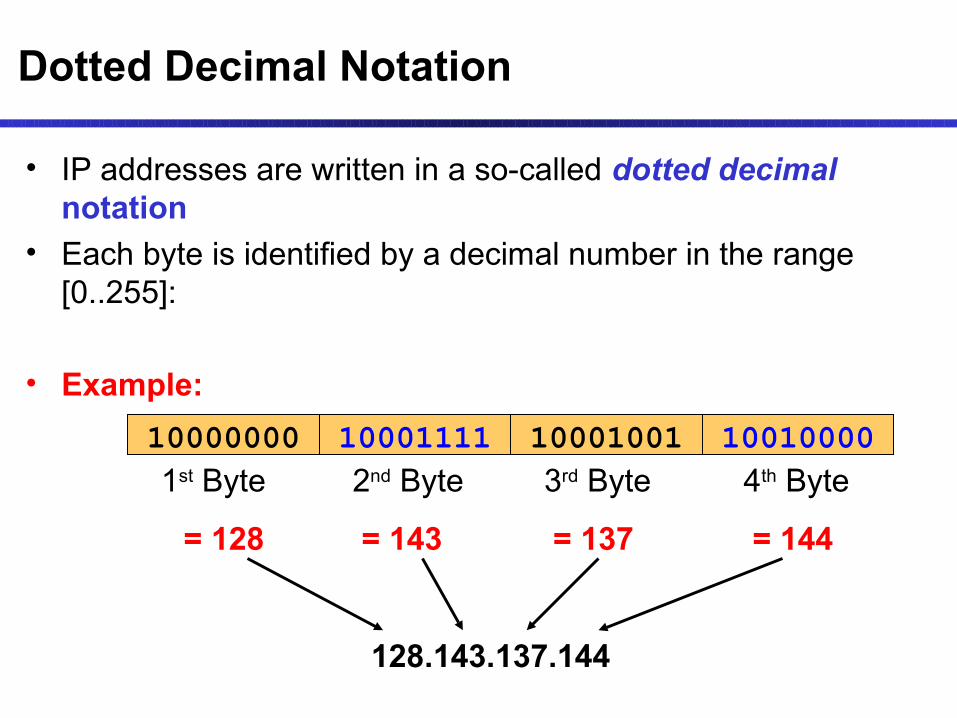
Dotted Decimal Notation
• IP addresses are written in a so-called dotted decimal notation
• Each byte is identified by a decimal number in the range [0..255]:
• Example:
1000111110000000 10001001 100100001st Byte
= 128
2nd Byte
= 143
3rd Byte
= 137
4th Byte
= 144
128.143.137.144

• The network prefix identifies a network and the host number identifies a specific host (actually, interface on the network).
• How do we know how long the network prefix is? – The network prefix is implicitly defined (see class-based
addressing)– The network prefix is indicated by a netmask.
Network prefix and Host number
network prefixnetwork prefix host numberhost number
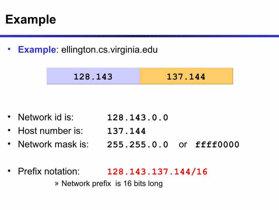
• Example: ellington.cs.virginia.edu
• Network id is: 128.143.0.0• Host number is: 137.144• Network mask is: 255.255.0.0 or ffff0000
• Prefix notation: 128.143.137.144/16» Network prefix is 16 bits long
Example
128.143128.143 137.144137.144

Subnetting
Subnetting
• Problem: Organizations have multiple networks which are independently managed – Solution 1: Allocate one or
more addresses for each network
• Difficult to manage• From the outside of the
organization, each network must be addressable.
– Solution 2: Add another level of hierarchy to the IP addressing structure
University NetworkUniversity Network
Medical School
Library
EngineeringSchool

Basic Idea of Subnetting
• Split the host number portion of an IP address into a subnet number and a (smaller) host number.
• Result is a 3-layer hierarchy
• Then: • Subnets can be freely assigned within the organization• Internally, subnets are treated as separate networks• Subnet structure is not visible outside the organization
network prefixnetwork prefix host numberhost number
subnet numbersubnet numbernetwork prefixnetwork prefix host numberhost number
extended network prefix

• Each layer-2 network (Ethernet segment, FDDI segment) is allocated a subnet address.
128.143.17.0 / 24
128.143.71.0 / 24
128.143.7.0 / 24
128.143.16.0 / 24
128.143.8.0 / 24
128.143.22.0 / 24
128.143.136.0 / 24
Typical Addressing Plan for an Organization that uses subnetting
128.143.0.0/16

Advantages of Subnetting
• With subnetting, IP addresses use a 3-layer hierarchy:» Network » Subnet» Host
• Improves efficiency of IP addresses by not consuming an entire address space for each physical network.
• Reduces router complexity. Since external routers do not know about subnetting, the complexity of routing tables at external routers is reduced.
• Note: Length of the subnet mask need not be identical at all subnetworks.

CIDR - Classless Interdomain Routing
• Goals:– Restructure IP address assignments to increase efficiency– Hierarchical routing aggregation to minimize route table
entries
Key Concept: The length of the network id (prefix) in the IP addresses is kept arbitrary
• Consequence: Routers advertise the IP address and the length of the prefix

CIDR Example
• CIDR notation of a network address:
192.0.2.0/18• "18" says that the first 18 bits are the network part of the
address (and 14 bits are available for specific host addresses)
• The network part is called the prefix
• Assume that a site requires a network address with 1000 addresses• With CIDR, the network is assigned a continuous block of 1024 addresses
with a 22-bit long prefix

CIDR: Prefix Size vs. Network Size
CIDR Block Prefix # of Host Addresses /27 32 hosts
/26 64 hosts
/25 128 hosts
/24 256 hosts
/23 512 hosts
/22 1,024 hosts
/21 2,048 hosts
/20 4,096 hosts
/19 8,192 hosts
/18 16,384 hosts
/17 32,768 hosts
/16 65,536 hosts
/15 131,072 hosts
/14 262,144 hosts
/13 524,288 hosts

CIDR and Address assignments
• Backbone ISPs obtain large block of IP addresses space and then reallocate portions of their address blocks to their customers.
Example: • Assume that an ISP owns the address block 206.0.64.0/18, which
represents 16,384 (214) IP addresses • Suppose a client requires 800 host addresses
• With classful addresses: need to assign a class B address (and waste ~64,700 addresses) or four individual Class Cs (and introducing 4 new routes into the global Internet routing tables)
• With CIDR: Assign a /22 block, e.g., 206.0.68.0/22, and allocated a block of 1,024 (210) IP addresses.

CIDR and Routing Information
206.0.64.0/18204.188.0.0/15209.88.232.0/21
Internet Backbone
ISP X owns:
Company X :
206.0.68.0/22
ISP y :
209.88.237.0/24
Organization z1 :
209.88.237.192/26
Organization z2 :
209.88.237.0/26

CIDR and Routing Information
206.0.64.0/18204.188.0.0/15209.88.232.0/21
Internet Backbone
ISP X owns:
Company X :
206.0.68.0/22
ISP y :
209.88.237.0/24
Organization z1 :
209.88.237.192/26
Organization z2 :
209.88.237.0/26
Backbone sends everything which matches the prefixes 206.0.64.0/18, 204.188.0.0/15, 209.88.232.0/21 to ISP X.
ISP X sends everything which matches the prefix: 206.0.68.0/22 to Company X,209.88.237.0/24 to ISP y
Backbone routers do not know anything about Company X, ISP Y, or Organizations z1, z2.
ISP X does not know about Organizations z1, z2.
ISP y sends everything which matches the prefix: 209.88.237.192/26 to Organizations z1 209.88.237.0/26 to Organizations z2

Example
Belongs to:
Cable & Wireless USA 207.0.0.0 - 207.3.255.255
11001111 00000010
207 2
01011000
88
10101010
170
11001111 00000010 01011000 00000000
Belongs to:
City of Charlottesville, VA: 207.2.88.0 - 207.2.92.255
11001111 00000000 00000000 00000000
You can find about ownership of IP addresses in North America via http://www.arin.net/whois/
• The IP Address: 207.2.88.170

CIDR and Routing
• Aggregation of routing table entries:– 128.143.0.0/16 and 128.142.0.0/16 are represented as
128.142.0.0/15• Longest prefix match: Routing table lookup finds the
routing entry that matches the longest prefix
What is the outgoing interface for
128.143.137.0 ?
Prefix Interface
128.0.0.0/4 interface #5
128.128.0.0/9 interface #2
128.143.128.0/17 interface #1
Routing table

IPv6 - IP Version 6
• IP Version 6– Is the successor to the currently used IPv4 – Specification completed in 1994
– Makes improvements to IPv4 (no revolutionary changes)
• One (not the only !) feature of IPv6 is a significant increase in size of the IP address to 128 bits (16 bytes)
• IPv6 will solve – for the foreseeable future – the problems with IP addressing

IPv6 Header
Application dataTCP HeaderEthernet Header Ethernet Trailer
Ethernet frame
IPv6 Header
version(4 bits)
Traffic Class(8 bits)
Flow Label(24 bits)
Payload Length (16 bits)Next Header
(8 bits)Hop Limits (8 bits)
Source IP address (128 bits)
32 bits
Destination IP address (128 bits)

IPv6 vs. IPv4: Address Comparison
• IPv4 has a maximum of
232 ≈ 4 billion addresses• IPv6 has a maximum of
2128 = (232)4 ≈ 4 billion x 4 billion x 4 billion x 4 billion addresses

Notation of IPv6 addresses
• Convention: The 128-bit IPv6 address is written as eight 16-bit integers (using hexadecimal digits for each integer)
CEDF:BP76:3245:4464:FACE:2E50:3025:DF12
• Short notation:• Abbreviations of leading zeroes:
CEDF:BP76:0000:0000:009E:0000:3025:DF12 CEDF:BP76:0:0:9E :0:3025:DF12
• “:0000:0000” can be written as “::”CEDF:BP76:0:0:FACE:0:3025:DF12 CEDF:BP76::FACE:0:3025:DF12
• IPv6 addresses derived from IPv4 addresses have 96 leading zero bits. Convention allows to use IPv4 notation for the last 32 bits.::80:8F:89:90 ::128.143.137.144

IPv6 Provider-Based Addresses
• The first IPv6 addresses will be allocated to a provider-based plan
• Type: Set to “010” for provider-based addresses• Registry: identifies the agency that registered the addressThe following fields have a variable length (recommeded length in “()”)
• Provider: Id of Internet access provider (16 bits)
• Subscriber: Id of the organization at provider (24 bits)
• Subnetwork: Id of subnet within organization (32 bits)
• Interface: identifies an interface at a node (48 bits)
Registry ID
Registry ID
Provider ID
Provider ID010010 Subscriber
ID Subscriber
IDInterface
IDInterface
IDSubnetwork
IDSubnetwork
ID

More on IPv6 Addresses
• The provider-based addresses have a similar flavor as CIDR addresses
• IPv6 provides address formats for:
– Unicast – identifies a single interface
– Multicast – identifies a group. Datagrams sent to a multicast address are sent to all members of the group
– Anycast – identifies a group. Datagrams sent to an anycast address are sent to one of the members in the group.


