Page 1
8/3/2019 MODULOS FAMILIA MOELLER
http://slidepdf.com/reader/full/modulos-familia-moeller 1/61
Hardware and Engineering
LE 4-100LE 4-300Local Expansion Modules
04/99 AWB 27-1270 GB1st published 1996, edition 06/96
2nd published 1999, edition 04/99
© Moeller GmbH, Bonn Author: Peter Roersch
Editor: Thomas Kracht
Translators: Eurotext, Terence OsbornFor Immediate Delivery call KMParts.com at (866) 595-9616
Page 2
8/3/2019 MODULOS FAMILIA MOELLER
http://slidepdf.com/reader/full/modulos-familia-moeller 2/61
Caution!
Dangerous electrical voltage!
Before commencing the installation
q Disconnect the power supply of thedevice.
q Ensure that the device cannot beaccidentally restarted.
q Verify isolation from the supply.q Earth and short circuit.q Cover or enclose neighbouring units that
are live.q Follow the engineering instructions
(AWA) of the device concerned.q Only suitably qualified personnel may
work on this device/system.q Before installation and before touching
the device ensure that you are free ofelectrostatic charge.
q Connecting cables and signal linesshould be installed so that inductive orcapacitive interference do not impair the
automation functions.q Install automation devices and related
operating elements in such a way thatthey are well protected againstunintentional operation.
q Suitable safety hardware and softwaremeasures should be implemented forthe I/O interface so that a line or wirebreakage on the signal side does notresult in undefined states in theautomation devices.
q Ensure a reliable electrical isolation ofthe low voltage for the 24 volt supply.Only use power supply units complyingwith IEC 60 364-4-41 or HD 384.4.41 S2.
q Deviations of the mains voltage from therated value must not exceed thetolerance limits given in thespecifications, otherwise this may causemalfunction and dangerous operation.
q Emergency stop devices complying withIEC/EN 60 204-1 must be effective in alloperating modes of the automationdevices. Unlatching the emergency-stopdevices must not cause uncontrolledoperation or restart.
q Devices that are designed for mountingin housings or control cabinets must onlybe operated and controlled after theyhave been installed with the housingclosed. Desktop or portable units must
only be operated and controlled inenclosed housings.q Measures should be taken to ensure the
proper restart of programs interruptedafter a voltage dip or failure. This shouldnot cause dangerous operating stateseven for a short time. If necessary,emergency-stop devices should beimplemented.
IBM is a registered trademark of InternationalBusiness Machines Corporation.
All other brand and product names aretrademarks or registered trademarks of theowner concerned.
All rights reserved, including those of thetranslation.No part of this manual may be reproduced inany form (printed, photocopy, microfilm orany otherprocess) or processed, duplicatedor distributed by means of electronicsystems without written permission ofMoeller GmbH, Bonn.Subject to alterations without notice.
For Immediate Delivery call KMParts.com at (866) 595-9616
Page 3
8/3/2019 MODULOS FAMILIA MOELLER
http://slidepdf.com/reader/full/modulos-familia-moeller 3/61
II 0 4 / 9 9 A W B 2 7 - 1 2 7 0 G B
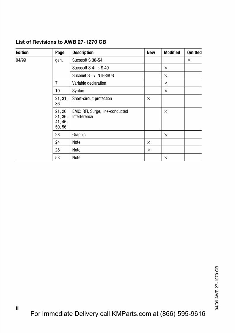
List of Revisions to AWB 27-1270 GB
Edition Page Description New Modified Omitted
04/99 gen. Sucosoft S 30-S4
Sucosoft S 4 → S 40
Suconet S → INTERBUS
7 Variable declaration
10 Syntax
21, 31,36
Short-circuit protection
21, 26,31, 36,41, 46,50, 56
EMC: RFI, Surge, line-conductedinterference
23 Graphic
24 Note
28 Note
53 Note
For Immediate Delivery call KMParts.com at (866) 595-9616
Page 4
8/3/2019 MODULOS FAMILIA MOELLER
http://slidepdf.com/reader/full/modulos-familia-moeller 4/61
1 0 4 / 9 9 A W B 2 7 - 1 2 7 0 G B
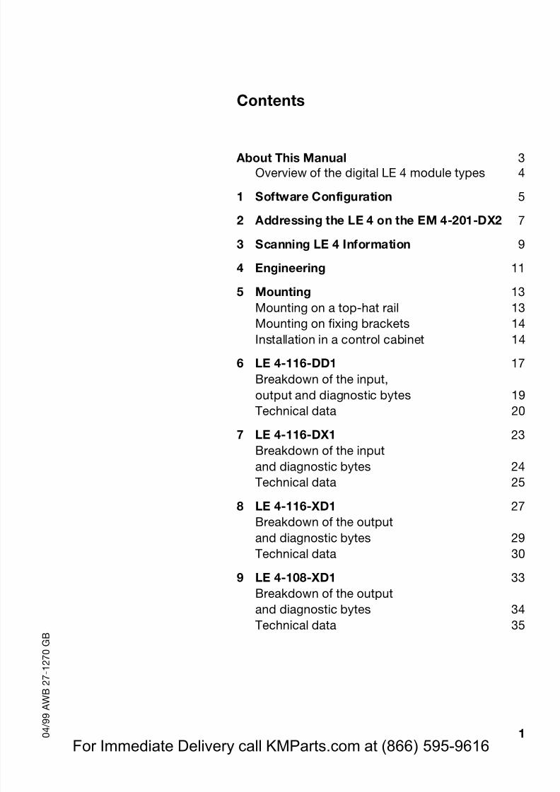
Contents
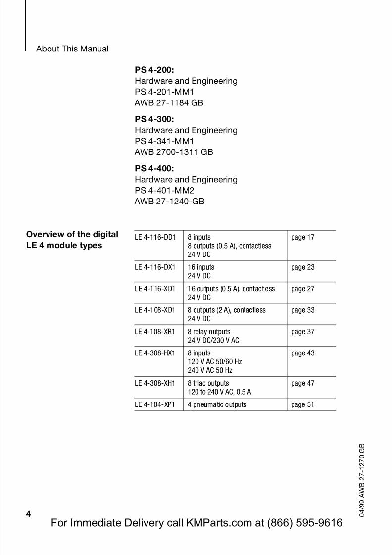
About This Manual 3Overview of the digital LE 4 module types 4
1 Software Configuration 5
2 Addressing the LE 4 on the EM 4-201-DX2 7
3 Scanning LE 4 Information 9
4 Engineering 115 Mounting 13
Mounting on a top-hat rail 13Mounting on fixing brackets 14Installation in a control cabinet 14
6 LE 4-116-DD1 17Breakdown of the input,output and diagnostic bytes 19Technical data 20
7 LE 4-116-DX1 23Breakdown of the inputand diagnostic bytes 24Technical data 25
8 LE 4-116-XD1 27Breakdown of the outputand diagnostic bytes 29Technical data 30
9 LE 4-108-XD1 33Breakdown of the outputand diagnostic bytes 34Technical data 35
For Immediate Delivery call KMParts.com at (866) 595-9616
Page 5
8/3/2019 MODULOS FAMILIA MOELLER
http://slidepdf.com/reader/full/modulos-familia-moeller 5/61
Contents
2 0 4 / 9 9 A W B 2 7 - 1 2 7 0 G B
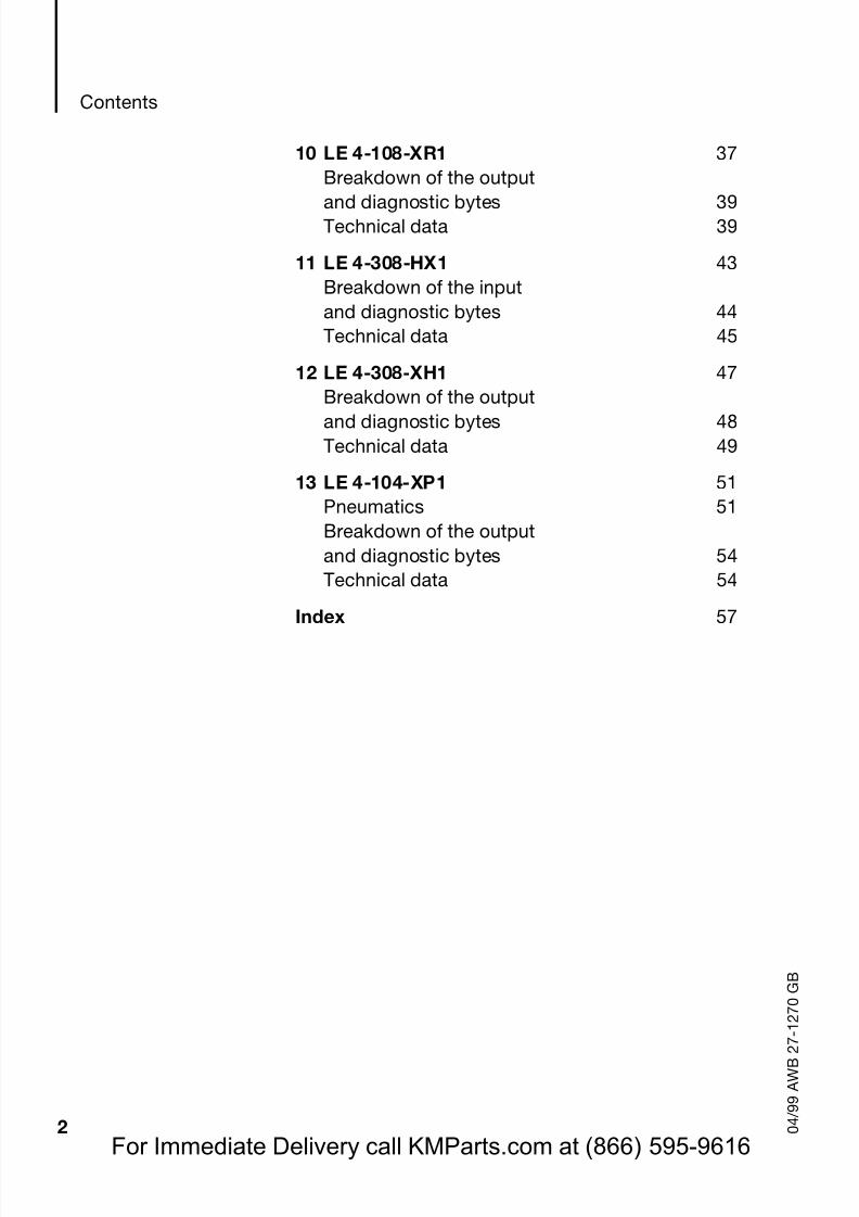
10 LE 4-108-XR1 37Breakdown of the output
and diagnostic bytes 39Technical data 39
11 LE 4-308-HX1 43Breakdown of the inputand diagnostic bytes 44Technical data 45
12 LE 4-308-XH1 47Breakdown of the output
and diagnostic bytes 48Technical data 49
13 LE 4-104-XP1 51Pneumatics 51Breakdown of the outputand diagnostic bytes 54Technical data 54
Index 57
For Immediate Delivery call KMParts.com at (866) 595-9616
Page 6
8/3/2019 MODULOS FAMILIA MOELLER
http://slidepdf.com/reader/full/modulos-familia-moeller 6/61
3 0 4 / 9 9 A W B 2 7 - 1 2 7 0 G B
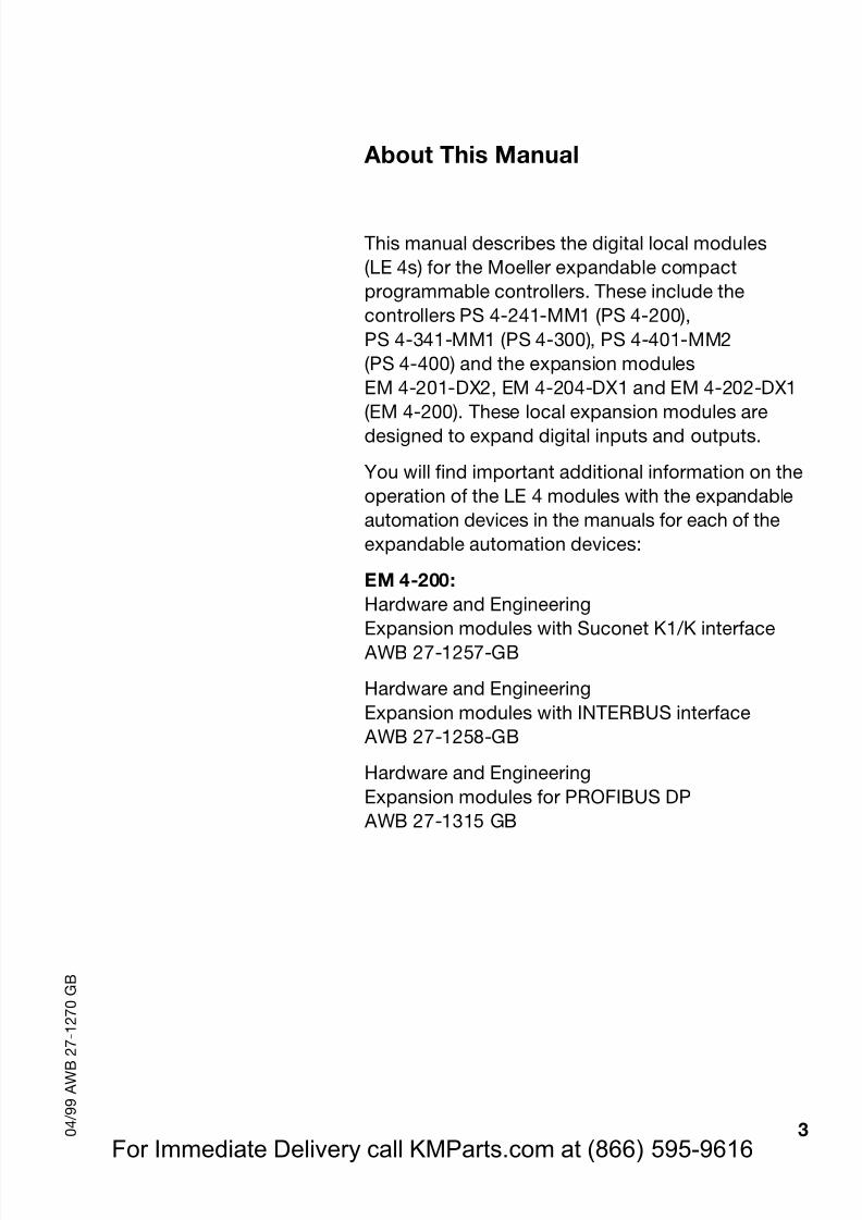
About This Manual
This manual describes the digital local modules(LE 4s) for the Moeller expandable compactprogrammable controllers. These include thecontrollers PS 4-241-MM1 (PS 4-200),PS 4-341-MM1 (PS 4-300), PS 4-401-MM2(PS 4-400) and the expansion modulesEM 4-201-DX2, EM 4-204-DX1 and EM 4-202-DX1
(EM 4-200). These local expansion modules aredesigned to expand digital inputs and outputs.
You will find important additional information on theoperation of the LE 4 modules with the expandableautomation devices in the manuals for each of theexpandable automation devices:
EM 4-200:Hardware and Engineering
Expansion modules with Suconet K1/K interface AWB 27-1257-GB
Hardware and EngineeringExpansion modules with INTERBUS interface
AWB 27-1258-GB
Hardware and EngineeringExpansion modules for PROFIBUS DP
AWB 27-1315 GB
For Immediate Delivery call KMParts.com at (866) 595-9616
Page 7
8/3/2019 MODULOS FAMILIA MOELLER
http://slidepdf.com/reader/full/modulos-familia-moeller 7/61
Page 8
8/3/2019 MODULOS FAMILIA MOELLER
http://slidepdf.com/reader/full/modulos-familia-moeller 8/61
5 0 4 / 9 9 A W B 2 7 - 1 2 7 0 G B
1 Software Configuration
When using PS 4-200 and PS 4-300, and PS 416master PLCs in conjunction with EM 4-201-DX2,configure the LE 4 devices in the Sucosoft S 40topology configurator.
Sucosoft S 40
You will find details on how to connect the LE 4, inconjunction with the EM 4-201-DX2, to the PS 416modular PLC in the manual “Engineering andConfiguration: Suconet K interface”(AWB 27-1210-GB), Chapter 4. To connect the LE 4to the PS 4-200 and PS 4-300 compact PLCs or inconjunction with the EM 4 devices of the 200 series,please refer to the manual “Sucosoft S 40 UserInterface” (AWB 2700-1305 GB), Chapter 5.
For Immediate Delivery call KMParts.com at (866) 595-9616
Page 9
8/3/2019 MODULOS FAMILIA MOELLER
http://slidepdf.com/reader/full/modulos-familia-moeller 9/61
6 0 4 / 9 9 A W B 2 7 - 1 2 7 0 G B
For Immediate Delivery call KMParts.com at (866) 595-9616
Page 10
8/3/2019 MODULOS FAMILIA MOELLER
http://slidepdf.com/reader/full/modulos-familia-moeller 10/61
7 0 4 / 9 9 A W B 2 7 - 1 2 7 0 G B
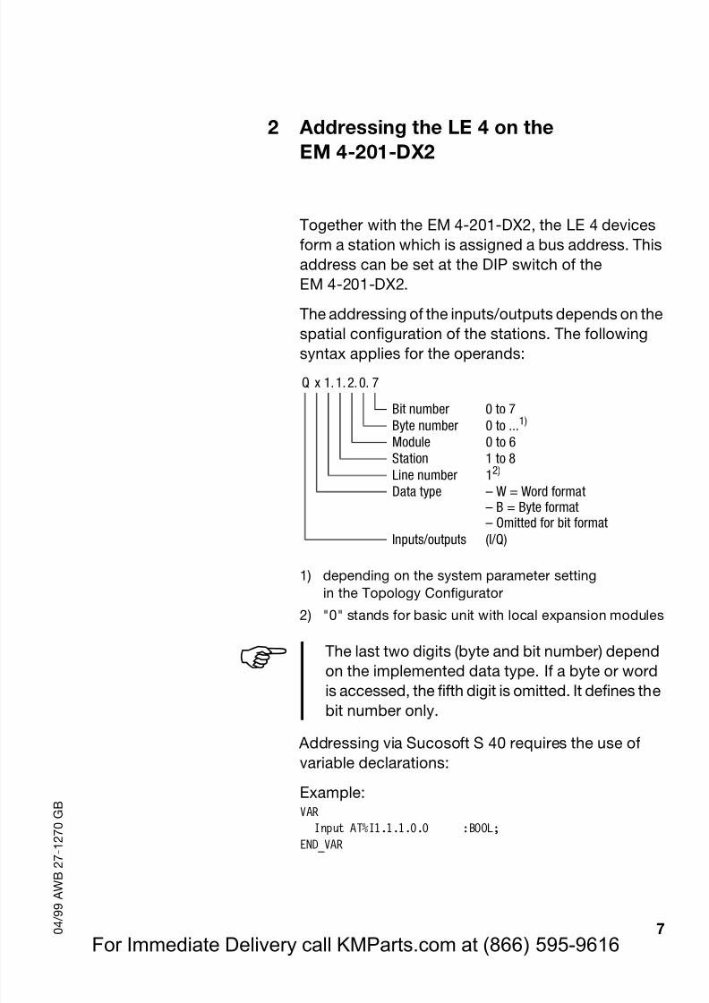
2 Addressing the LE 4 on theEM 4-201-DX2
Together with the EM 4-201-DX2, the LE 4 devicesform a station which is assigned a bus address. Thisaddress can be set at the DIP switch of theEM 4-201-DX2.
The addressing of the inputs/outputs depends on thespatial configuration of the stations. The followingsyntax applies for the operands:
1) depending on the system parameter settingin the Topology Configurator
2) "0" stands for basic unit with local expansion modules
Addressing via Sucosoft S 40 requires the use ofvariable declarations:
Example:VAR
Input AT%I1.1.1.0.0 :BOOL;END_VAR
Q x 1. 1. 2. 0. 7
Bit number 0 to 7Byte number 0 to ...1)
Module 0 to 6Station 1 to 8Line number 12)
Data type – W = Word format– B = Byte format– Omitted for bit format
Inputs/outputs (I/Q)
! The last two digits (byte and bit number) dependon the implemented data type. If a byte or word
is accessed, the fifth digit is omitted. It defines thebit number only.
For Immediate Delivery call KMParts.com at (866) 595-9616
Page 11
8/3/2019 MODULOS FAMILIA MOELLER
http://slidepdf.com/reader/full/modulos-familia-moeller 11/61
8 0 4 / 9 9 A W B 2 7 - 1 2 7 0 G B
For Immediate Delivery call KMParts.com at (866) 595-9616
Page 12
8/3/2019 MODULOS FAMILIA MOELLER
http://slidepdf.com/reader/full/modulos-familia-moeller 12/61
9 0 4 / 9 9 A W B 2 7 - 1 2 7 0 G B
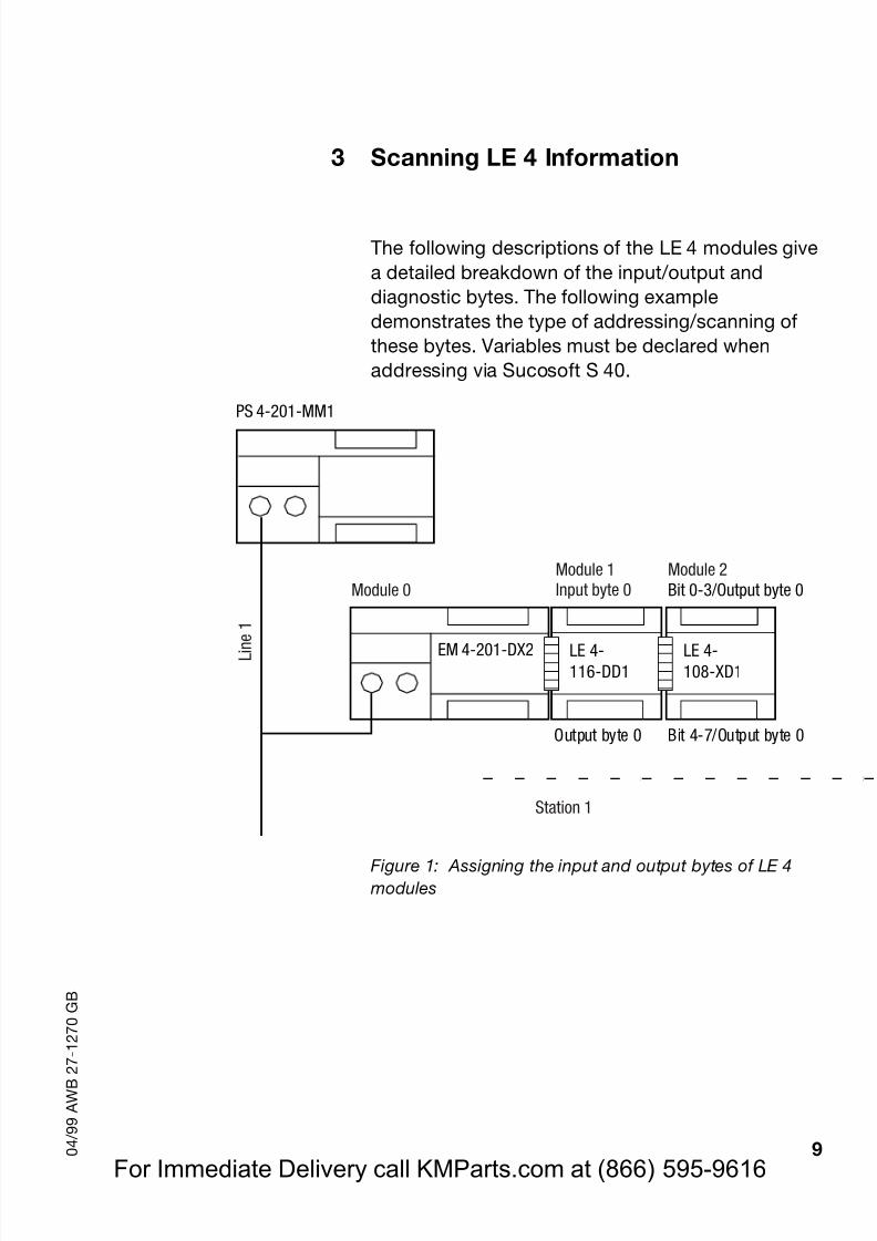
3 Scanning LE 4 Information
The following descriptions of the LE 4 modules givea detailed breakdown of the input/output anddiagnostic bytes. The following exampledemonstrates the type of addressing/scanning ofthese bytes. Variables must be declared whenaddressing via Sucosoft S 40.
Figure 1: Assigning the input and output bytes of LE 4 modules
EM 4-201-DX2
PS 4-201-MM1
Module 2Bit 0-3/Output byte 0
LE 4-116-DD1
LE 4-108-XD1
Output byte 0 Bit 4-7/Output byte 0
ì ï ï ï ï ï í ï ï ï ï ï î
L i n e
1
Module 0Module 1Input byte 0
Station 1
For Immediate Delivery call KMParts.com at (866) 595-9616
Page 13
8/3/2019 MODULOS FAMILIA MOELLER
http://slidepdf.com/reader/full/modulos-familia-moeller 13/61
Scanning LE 4 Information
10 0 4 / 9 9 A W B 2 7 - 1 2 7 0 G B
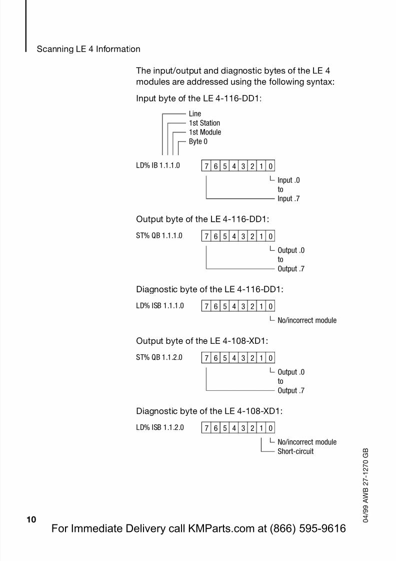
The input/output and diagnostic bytes of the LE 4modules are addressed using the following syntax:
Input byte of the LE 4-116-DD1:
Output byte of the LE 4-116-DD1:
Diagnostic byte of the LE 4-116-DD1:
Output byte of the LE 4-108-XD1:
Diagnostic byte of the LE 4-108-XD1:
Line1st Station1st ModuleByte 0
LD% IB 1.1.1.0 7 6 5 4 3 2 1 0
Input .0
toInput .7
ST% QB 1.1.1.0 7 6 5 4 3 2 1 0
Output .0toOutput .7
LD% ISB 1.1.1.0 7 6 5 4 3 2 1 0
No/incorrect module
ST% QB 1.1.2.0 7 6 5 4 3 2 1 0
Output .0toOutput .7
LD% ISB 1.1.2.0 7 6 5 4 3 2 1 0
No/incorrect moduleShort-circuit
For Immediate Delivery call KMParts.com at (866) 595-9616
Page 14
8/3/2019 MODULOS FAMILIA MOELLER
http://slidepdf.com/reader/full/modulos-familia-moeller 14/61
11 0 4 / 9 9 A W B 2 7 - 1 2 7 0 G B
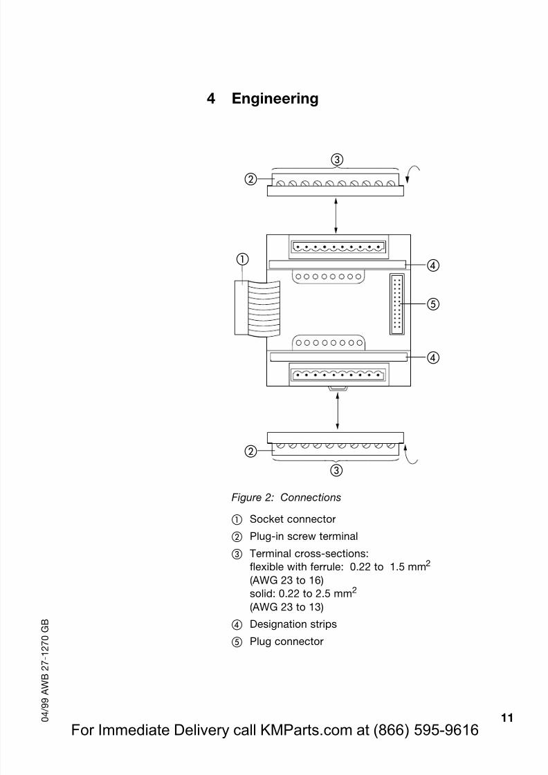
4 Engineering
Figure 2: Connections
Socket connector
Plug-in screw terminalTerminal cross-sections:flexible with ferrule: 0.22 to 1.5 mm 2
(AWG 23 to 16)solid: 0.22 to 2.5 mm 2
(AWG 23 to 13)
Designation strips
Plug connector
For Immediate Delivery call KMParts.com at (866) 595-9616
Page 15
8/3/2019 MODULOS FAMILIA MOELLER
http://slidepdf.com/reader/full/modulos-familia-moeller 15/61
Engineering
12 0 4 / 9 9 A W B 2 7 - 1 2 7 0 G B
! The connections of the LE 4-104-XP1 aredescribed in the relevant chapter.
! The LE 4-308-HX1 and LE 4-308-XH1 localexpansion modules may only be connected tothe EM 4-201-DX2 and EM 4-202-DX1version 02 or higher.
! In the case of mains circuits in OvervoltageCategory III (power supply and relay outputs),appropriate measures must be taken to ensure
safe isolation (e. g. using a transformer whichprovides at least basic insulation between theprimary and secondary sides).
! Please also refer to the configuration instructionsin the manual "EMC Engineering Guidelines for
Automation Devices" (AWB 27-1287-GB).
For Immediate Delivery call KMParts.com at (866) 595-9616
Page 16
8/3/2019 MODULOS FAMILIA MOELLER
http://slidepdf.com/reader/full/modulos-familia-moeller 16/61
13 0 4 / 9 9 A W B 2 7 - 1 2 7 0 G B
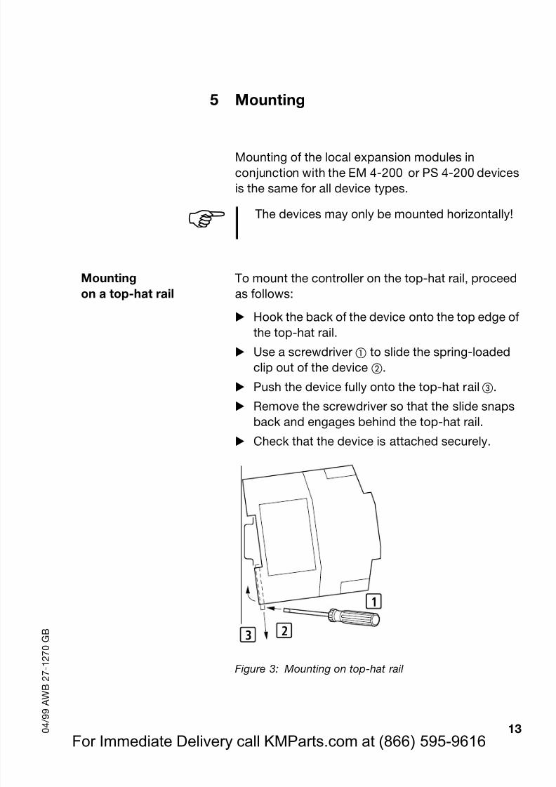
5 Mounting
Mounting of the local expansion modules inconjunction with the EM 4-200 or PS 4-200 devicesis the same for all device types.
Mountingon a top-hat rail
To mount the controller on the top-hat rail, proceedas follows:
Hook the back of the device onto the top edge ofthe top-hat rail.
Use a screwdriver to slide the spring-loadedclip out of the device .
Push the device fully onto the top-hat rail .
Remove the screwdriver so that the slide snapsback and engages behind the top-hat rail.
Check that the device is attached securely.
Figure 3: Mounting on top-hat rail
! The devices may only be mounted horizontally!
1
23
For Immediate Delivery call KMParts.com at (866) 595-9616
Page 17
8/3/2019 MODULOS FAMILIA MOELLER
http://slidepdf.com/reader/full/modulos-familia-moeller 17/61
Mounting
14 0 4 / 9 9 A W B 2 7 - 1 2 7 0 G B
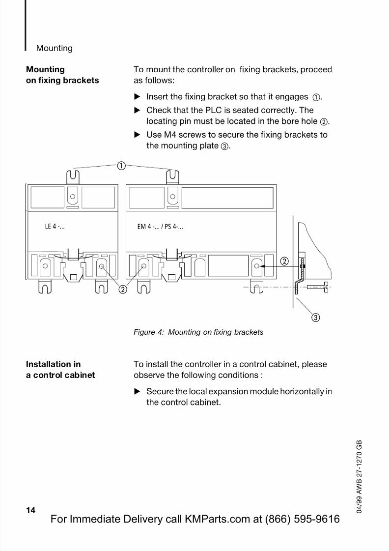
Mountingon fixing brackets
To mount the controller on fixing brackets, proceedas follows:
Insert the fixing bracket so that it engages .Check that the PLC is seated correctly. Thelocating pin must be located in the bore hole .
Use M4 screws to secure the fixing brackets tothe mounting plate .
Figure 4: Mounting on fixing brackets
Installation in
a control cabinet
To install the controller in a control cabinet, please
observe the following conditions :Secure the local expansion module horizontally inthe control cabinet.
LE 4 -... EM 4 -... / PS 4-...LE 4 -... EM 4 -... / PS 4-...
For Immediate Delivery call KMParts.com at (866) 595-9616
Page 18
8/3/2019 MODULOS FAMILIA MOELLER
http://slidepdf.com/reader/full/modulos-familia-moeller 18/61
Installation ina control cabinet
15 0 4 / 9 9 A W B 2 7 - 1 2 7 0 G B
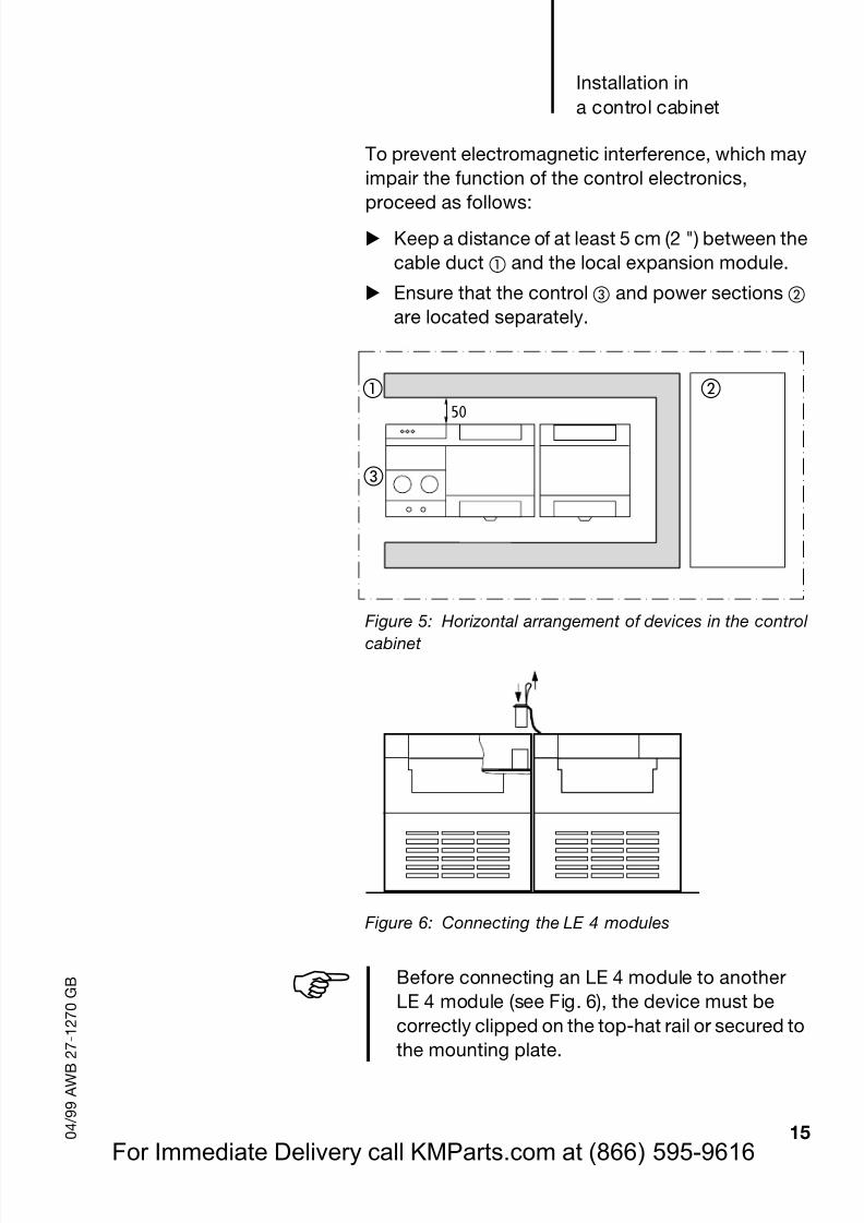
To prevent electromagnetic interference, which mayimpair the function of the control electronics,
proceed as follows:Keep a distance of at least 5 cm (2 ") between thecable duct and the local expansion module.
Ensure that the control and power sections are located separately.
Figure 5: Horizontal arrangement of devices in the controlcabinet
Figure 6: Connecting the LE 4 modules
50
! Before connecting an LE 4 module to anotherLE 4 module (see Fig. 6) , the device must becorrectly clipped on the top-hat rail or secured to
the mounting plate.
For Immediate Delivery call KMParts.com at (866) 595-9616
Page 19
8/3/2019 MODULOS FAMILIA MOELLER
http://slidepdf.com/reader/full/modulos-familia-moeller 19/61
Page 20
8/3/2019 MODULOS FAMILIA MOELLER
http://slidepdf.com/reader/full/modulos-familia-moeller 20/61
17 0 4 / 9 9 A W B 2 7 - 1 2 7 0 G B
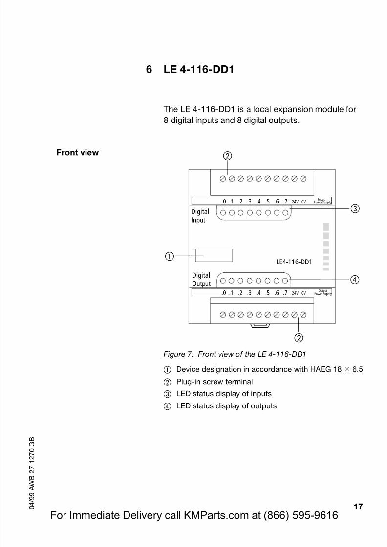
6 LE 4-116-DD1
The LE 4-116-DD1 is a local expansion module for8 digital inputs and 8 digital outputs.
Front view
Figure 7: Front view of the LE 4-116-DD1
Device designation in accordance with HAEG 18 6.5
Plug-in screw terminal
LED status display of inputs
LED status display of outputs
LE4-116-DD1
.0 .1 .2 .3 .4 .5 .6 .7 24V 0V
DigitalOutput
DigitalInput
OutputPower Supply
InputPower Supply
.0 .1 .2 .3 .4 .5 .6 .7 24V 0V
For Immediate Delivery call KMParts.com at (866) 595-9616
Page 21
8/3/2019 MODULOS FAMILIA MOELLER
http://slidepdf.com/reader/full/modulos-familia-moeller 21/61
LE 4-116-DD1
18 0 4 / 9 9 A W B 2 7 - 1 2 7 0 G B
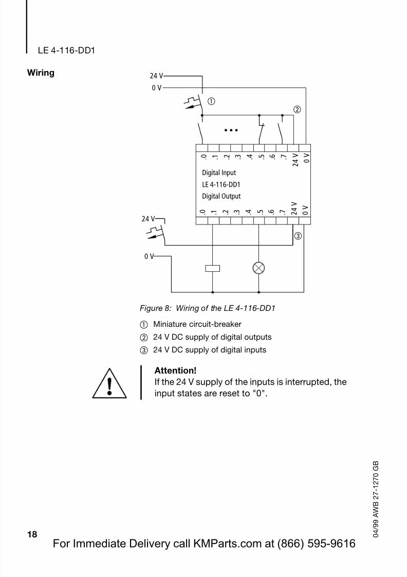
Wiring
Figure 8: Wiring of the LE 4-116-DD1
Miniature circuit-breaker
24 V DC supply of digital outputs
24 V DC supply of digital inputs
24 V0 V
. 0 . 1 . 7 . 2 . 3 . 4 . 5 . 6
Digital Input
Digital Output . 0 . 1 . 7 2
4 V
0 V
. 2 . 3 . 4 . 5 . 6
LE 4-116-DD1
0 V
2 4 V
24 V
0 V
Attention!If the 24 V supply of the inputs is interrupted, the
input states are reset to "0".
For Immediate Delivery call KMParts.com at (866) 595-9616
Page 22
8/3/2019 MODULOS FAMILIA MOELLER
http://slidepdf.com/reader/full/modulos-familia-moeller 22/61
Breakdown of theinput, outputand diagnostic bytes
19 0 4 / 9 9 A W B 2 7 - 1 2 7 0 G B
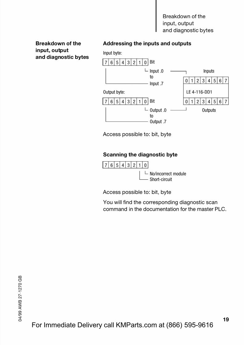
Breakdown of theinput, output
and diagnostic bytes
Addressing the inputs and outputs
Access possible to: bit, byte
Scanning the diagnostic byte
Access possible to: bit, byte
You will find the corresponding diagnostic scancommand in the documentation for the master PLC.
Input byte:
7 6 5 4 3 2 1 0 Bit
Input .0 Inputsto
0 1 2 3 4 5 6 7Input .7
Output byte: LE 4-116-DD1
7 6 5 4 3 2 1 0 Bit 0 1 2 3 4 5 6 7
Output .0 OutputstoOutput .7
7 6 5 4 3 2 1 0
No/incorrect moduleShort-circuit
For Immediate Delivery call KMParts.com at (866) 595-9616
Page 23
8/3/2019 MODULOS FAMILIA MOELLER
http://slidepdf.com/reader/full/modulos-familia-moeller 23/61
LE 4-116-DD1
20 0 4 / 9 9 A W B 2 7 - 1 2 7 0 G B
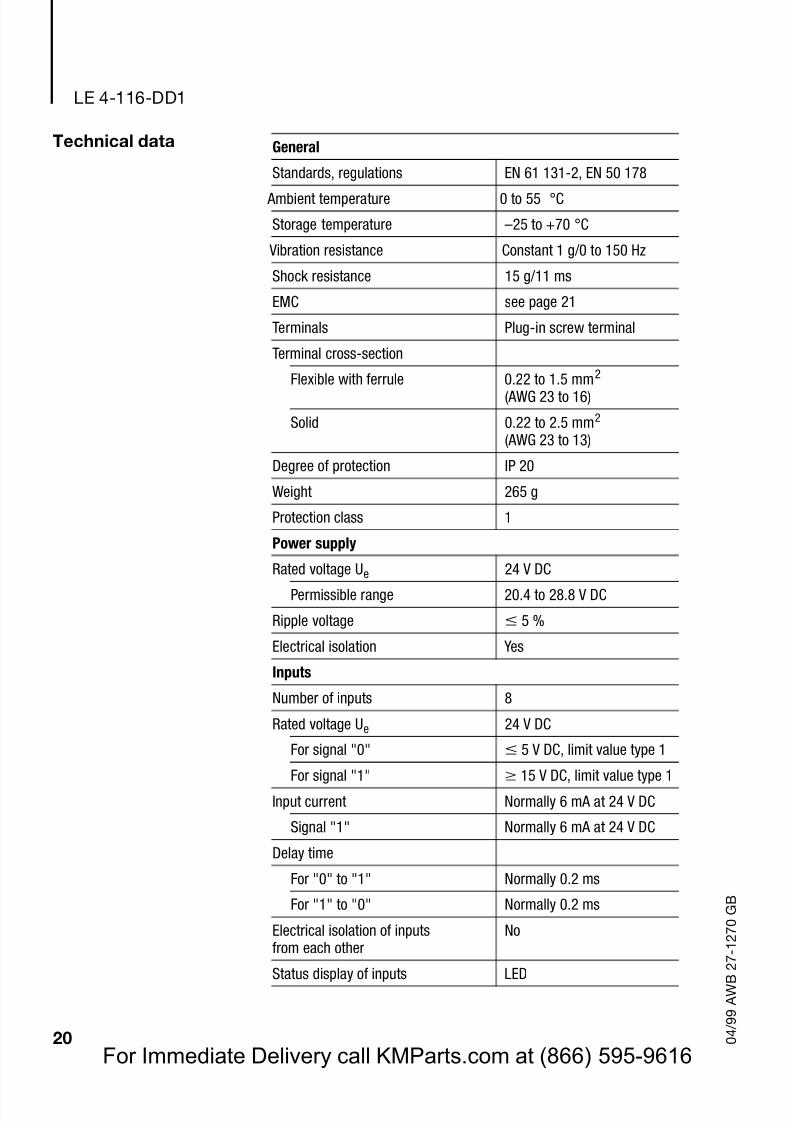
Technical data General
Standards, regulations EN 61 131-2, EN 50 178
Ambient temperature 0 to 55 °C
Storage temperature –25 to +70 °C
Vibration resistance Constant 1 g/0 to 150 Hz
Shock resistance 15 g/11 ms
EMC seepage 21
Terminals Plug-in screw terminal
Terminal cross-section
Flexible with ferrule 0.22 to 1.5 mm2
(AWG 23 to 16)
Solid 0.22 to 2.5 mm2
(AWG 23 to 13)
Degree of protection IP 20
Weight 265 g
Protection class 1
Power supply
Rated voltage Ue
24 V DC
Permissible range 20.4 to 28.8 V DC
Ripple voltage 5 %
Electrical isolation Yes
Inputs
Number of inputs 8
Rated voltage Ue 24 V DC
For signal "0" 5 V DC, limit value type 1
For signal "1" 15 V DC, limit value type 1
Input current Normally 6 mA at 24 V DC
Signal "1" Normally 6 mA at 24 V DC
Delay time
For "0" to "1" Normally 0.2 ms
For "1" to "0" Normally 0.2 ms
Electrical isolation of inputsfrom each other
No
Status display of inputs LED
For Immediate Delivery call KMParts.com at (866) 595-9616
Page 24
8/3/2019 MODULOS FAMILIA MOELLER
http://slidepdf.com/reader/full/modulos-familia-moeller 24/61
Technical data
21 0 4 / 9 9 A W B 2 7 - 1 2 7 0 G B
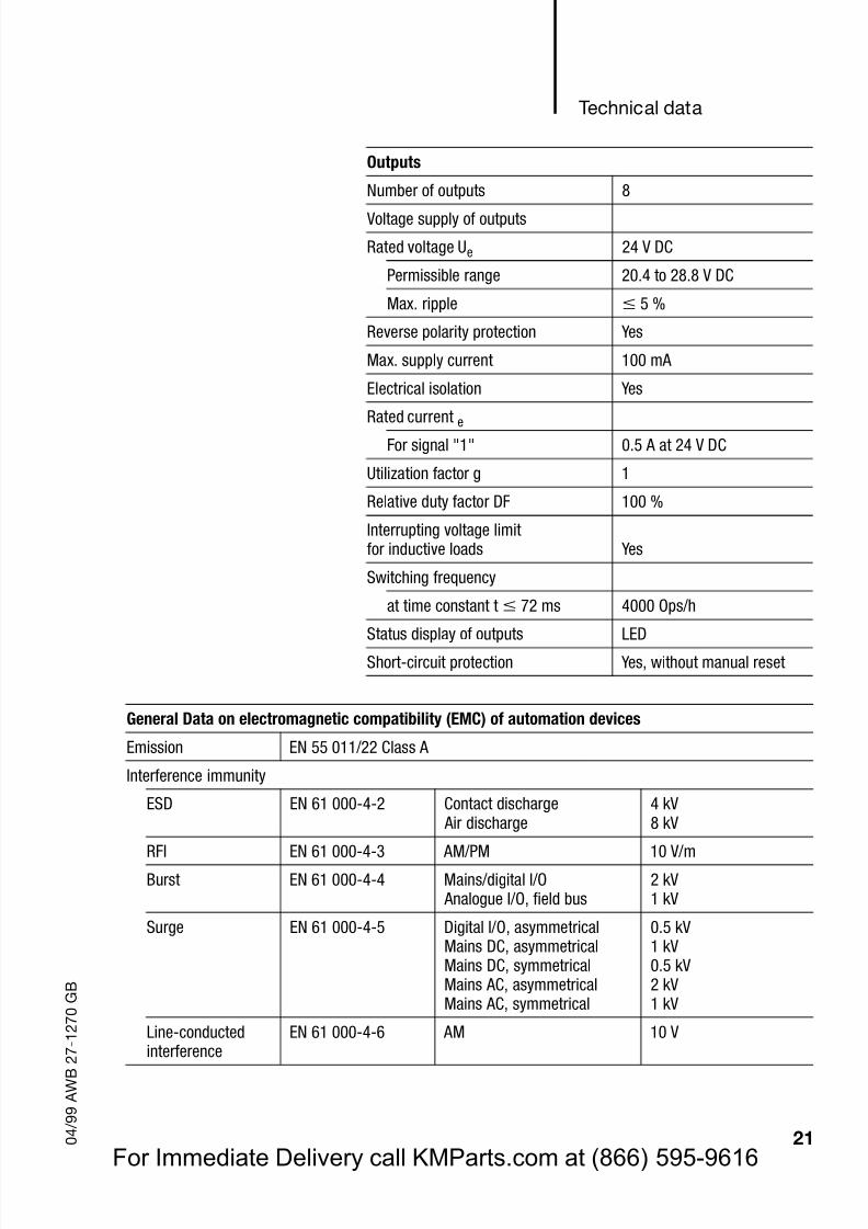
Outputs
Number of outputs 8
Voltage supply of outputs
Rated voltage Ue 24 V DC
Permissible range 20.4 to 28.8 V DC
Max. ripple 5 %
Reverse polarity protection Yes
Max. supply current 100 mA
Electrical isolation Yes
Rated current eFor signal "1" 0.5 A at 24 V DC
Utilization factor g 1
Relative duty factor DF 100 %
Interrupting voltage limitfor inductive loads Yes
Switching frequency
at time constant t 72 ms 4000 Ops/h
Status display of outputs LEDShort-circuit protection Yes, without manual reset
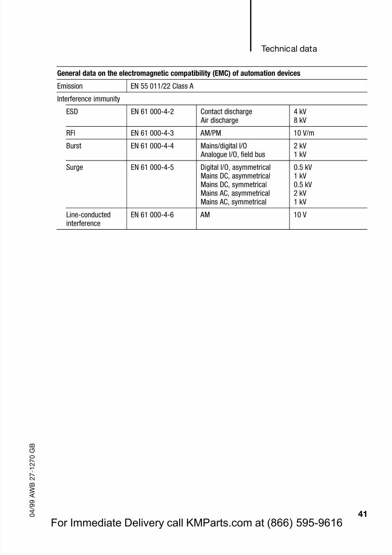
General Data on electromagnetic compatibility (EMC) of automation devices
Emission EN 55 011/22 Class A
Interference immunity
ESD EN 61 000-4-2 Contact discharge Air discharge
4 kV8 kV
RFI EN 61 000-4-3 AM/PM 10 V/m
Burst EN 61 000-4-4 Mains/digital I/O Analogue I/O, field bus
2 kV1 kV
Surge EN 61 000-4-5 Digital I/O, asymmetricalMains DC, asymmetricalMains DC, symmetricalMains AC, asymmetricalMains AC, symmetrical
0.5 kV1 kV0.5 kV2 kV1 kV
Line-conducted
interference
EN 61 000-4-6 AM 10 V
For Immediate Delivery call KMParts.com at (866) 595-9616
Page 25
8/3/2019 MODULOS FAMILIA MOELLER
http://slidepdf.com/reader/full/modulos-familia-moeller 25/61
22 0 4 / 9 9 A W B 2 7 - 1 2 7 0 G B
For Immediate Delivery call KMParts.com at (866) 595-9616
Page 26
8/3/2019 MODULOS FAMILIA MOELLER
http://slidepdf.com/reader/full/modulos-familia-moeller 26/61
23 0 4 / 9 9 A W B 2 7 - 1 2 7 0 G B
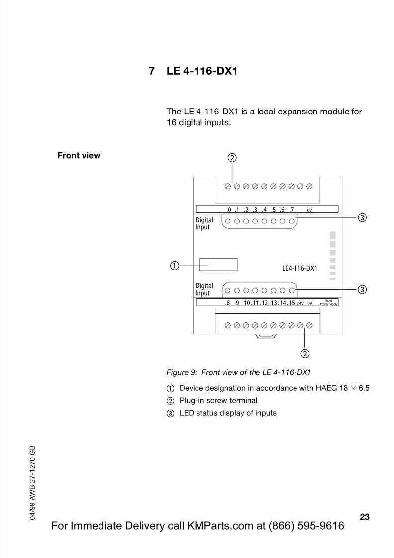
7 LE 4-116-DX1
The LE 4-116-DX1 is a local expansion module for16 digital inputs.
Front view
Figure 9: Front view of the LE 4-116-DX1
Device designation in accordance with HAEG 18 6.5
Plug-in screw terminal
LED status display of inputs
LE4-116-DX1
.0 .1 .2 .3 .4 .5 .6 .7 0V
.8 .9 .10 .11 .12 .13 .14 .15 24V 0V
DigitalInput
DigitalInputInput
Power Supply
For Immediate Delivery call KMParts.com at (866) 595-9616
Page 27
8/3/2019 MODULOS FAMILIA MOELLER
http://slidepdf.com/reader/full/modulos-familia-moeller 27/61
LE 4-116-DX1
24 0 4 / 9 9 A W B 2 7 - 1 2 7 0 G B
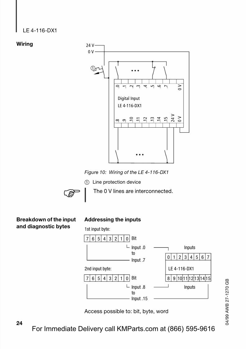
Wiring
Figure 10: Wiring of the LE 4-116-DX1
Line protection device
Breakdown of the inputand diagnostic bytes
Addressing the inputs
Access possible to: bit, byte, word
24 V0 V
. 0 . 1 . 7 0 V . 2 . 3 . 4 . 5 . 6
Digital Input
. 8 . 9 . 1 5
2 4 V
0
V
. 1 0
. 1 1
. 1 2
. 1 3
. 1 4
LE 4-116-DX1
! The 0 V lines are interconnected.
1st input byte:
7 6 5 4 3 2 1 0 BitInput .0 Inputsto
0 1 2 3 4 5 6 7Input .7
2nd input byte: LE 4-116-DX1
7 6 5 4 3 2 1 0 Bit 8 9 10 11 12 13 14 15
Input .8 Inputsto
Input .15
For Immediate Delivery call KMParts.com at (866) 595-9616
Page 28
8/3/2019 MODULOS FAMILIA MOELLER
http://slidepdf.com/reader/full/modulos-familia-moeller 28/61
Technical data
25 0 4 / 9 9 A W B 2 7 - 1 2 7 0 G B
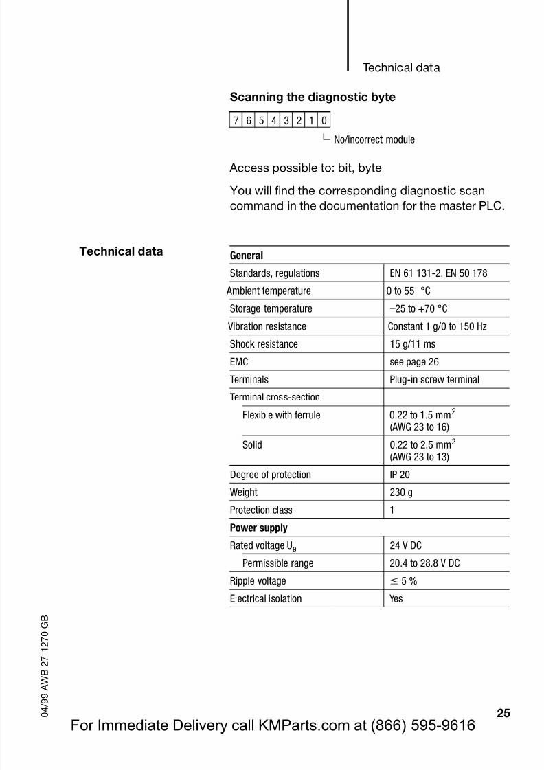
Scanning the diagnostic byte
Access possible to: bit, byte
You will find the corresponding diagnostic scancommand in the documentation for the master PLC.
Technical data
7 6 5 4 3 2 1 0
No/incorrect module
General
Standards, regulations EN 61 131-2, EN 50 178
Ambient temperature 0 to 55 °C
Storage temperature –25 to +70 °C
Vibration resistance Constant 1 g/0 to 150 Hz
Shock resistance 15 g/11 ms
EMC seepage 26
Terminals Plug-in screw terminal
Terminal cross-sectionFlexible with ferrule 0.22 to 1.5 mm2
(AWG 23 to 16)
Solid 0.22 to 2.5 mm2
(AWG 23 to 13)
Degree of protection IP 20
Weight 230 g
Protection class 1
Power supplyRated voltage Ue 24 V DC
Permissible range 20.4 to 28.8 V DC
Ripple voltage 5 %
Electrical isolation Yes
For Immediate Delivery call KMParts.com at (866) 595-9616
Page 29
8/3/2019 MODULOS FAMILIA MOELLER
http://slidepdf.com/reader/full/modulos-familia-moeller 29/61
LE 4-116-DX1
26 0 4 / 9 9 A W B 2 7 - 1 2 7 0 G B
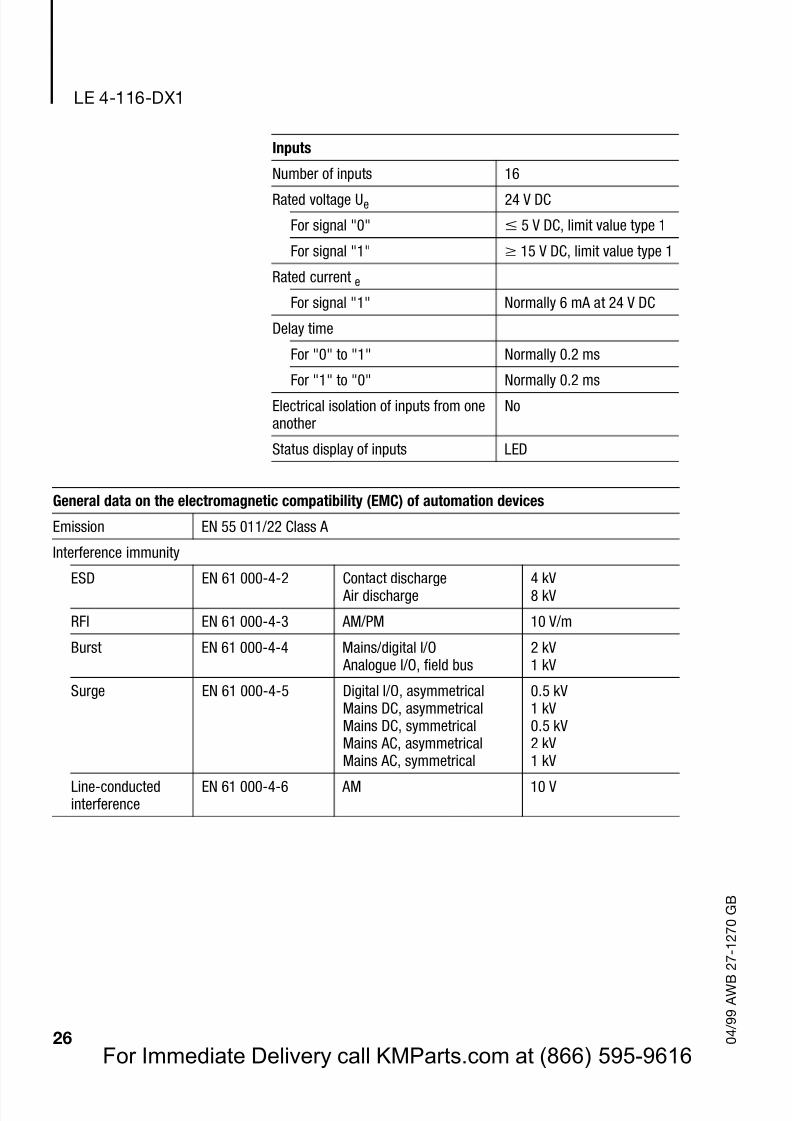
Inputs
Number of inputs 16
Rated voltage Ue 24 V DC
For signal "0" 5 V DC, limit value type 1
For signal "1" 15 V DC, limit value type 1
Rated current e
For signal "1" Normally 6 mA at 24 V DC
Delay time
For "0" to "1" Normally 0.2 ms
For "1" to "0" Normally 0.2 msElectrical isolation of inputs from oneanother
No
Status display of inputs LED
General data on the electromagnetic compatibility (EMC) of automation devices
Emission EN 55 011/22 Class A
Interference immunity
ESD EN 61 000-4-2 Contact discharge Air discharge
4 kV8 kV
RFI EN 61 000-4-3 AM/PM 10 V/m
Burst EN 61 000-4-4 Mains/digital I/O Analogue I/O, field bus
2 kV1 kV
Surge EN 61 000-4-5 Digital I/O, asymmetricalMains DC, asymmetricalMains DC, symmetricalMains AC, asymmetricalMains AC, symmetrical
0.5 kV1 kV0.5 kV2 kV1 kV
Line-conductedinterference
EN 61 000-4-6 AM 10 V
For Immediate Delivery call KMParts.com at (866) 595-9616
Page 30
8/3/2019 MODULOS FAMILIA MOELLER
http://slidepdf.com/reader/full/modulos-familia-moeller 30/61
27 0 4 / 9 9 A W B 2 7 - 1 2 7 0 G B
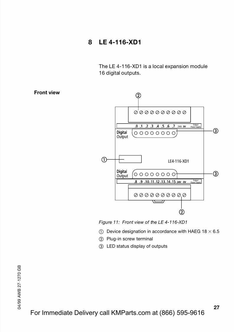
8 LE 4-116-XD1
The LE 4-116-XD1 is a local expansion module16 digital outputs.
Front view
Figure 11: Front view of the LE 4-116-XD1
Device designation in accordance with HAEG 18 6.5
Plug-in screw terminal
LED status display of outputs
LE4-116-XD1
.0 .1 .2 .3 .4 .5 .6 .7 0V
.8 .9 .10 .11 .12 .13 .14 .15 24V 0V
DigitalOutput
OutputPower Supply
OutputPower Supply.0 .1 .2 .3 .4 .5 .6 .7 0V24V
.8 .9 .10 .11 .12 .13 .14 .15 24V 0V
Digital
DigitalOutputDigital
For Immediate Delivery call KMParts.com at (866) 595-9616
Page 31
8/3/2019 MODULOS FAMILIA MOELLER
http://slidepdf.com/reader/full/modulos-familia-moeller 31/61
LE 4-116-XD1
28 0 4 / 9 9 A W B 2 7 - 1 2 7 0 G B
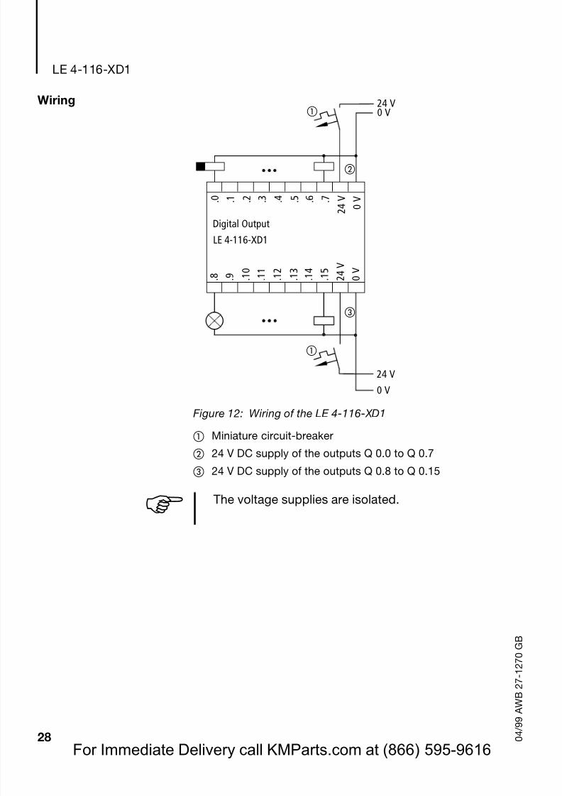
Wiring
Figure 12: Wiring of the LE 4-116-XD1
Miniature circuit-breaker
24 V DC supply of the outputs Q 0.0 to Q 0.7
24 V DC supply of the outputs Q 0.8 to Q 0.15
24 V0 V
. 0 . 1 . 7
2 4 V
0 V . 2 . 3 . 4 . 5 . 6
Digital Output
. 8 . 9 . 1 5
2 4
V
0 V
. 1 0
. 1 1
. 1 2
. 1 3
. 1 4
LE 4-116-XD1
24 V0 V
! The voltage supplies are isolated.
For Immediate Delivery call KMParts.com at (866) 595-9616
Page 32
8/3/2019 MODULOS FAMILIA MOELLER
http://slidepdf.com/reader/full/modulos-familia-moeller 32/61
Breakdown of the outputand diagnostic bytes
29 0 4 / 9 9 A W B 2 7 - 1 2 7 0 G B
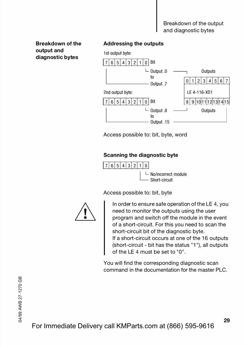
Breakdown of theoutput and
diagnostic bytes
Addressing the outputs
Access possible to: bit, byte, word
Scanning the diagnostic byte
Access possible to: bit, byte
You will find the corresponding diagnostic scancommand in the documentation for the master PLC.
1st output byte:
7 6 5 4 3 2 1 0 Bit
Output .0 Outputsto
0 1 2 3 4 5 6 7Output .7
2nd output byte: LE 4-116-XD1
7 6 5 4 3 2 1 0 Bit 8 9 10 11 12 13 14 15
Output .8 OutputstoOutput .15
7 6 5 4 3 2 1 0
No/incorrect moduleShort-circuit
In order to ensure safe operation of the LE 4, youneed to monitor the outputs using the userprogram and switch off the module in the eventof a short-circuit. For this you need to scan theshort-circuit bit of the diagnostic byte.
If a short-circuit occurs at one of the 16 outputs(short-circuit - bit has the status "1"), all outputsof the LE 4 must be set to "0".
For Immediate Delivery call KMParts.com at (866) 595-9616
Page 33
8/3/2019 MODULOS FAMILIA MOELLER
http://slidepdf.com/reader/full/modulos-familia-moeller 33/61
LE 4-116-XD1
30 0 4 / 9 9 A W B 2 7 - 1 2 7 0 G B
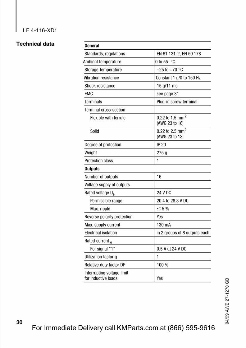
Technical data General
Standards, regulations EN 61 131-2, EN 50 178
Ambient temperature 0 to 55 °C
Storage temperature –25 to +70 °C
Vibration resistance Constant 1 g/0 to 150 Hz
Shock resistance 15 g/11 ms
EMC seepage 31
Terminals Plug-in screw terminal
Terminal cross-section
Flexible with ferrule 0.22 to 1.5 mm2
(AWG 23 to 16)
Solid 0.22 to 2.5 mm2
(AWG 23 to 13)
Degree of protection IP 20
Weight 275 g
Protection class 1
Outputs
Number of outputs 16
Voltage supply of outputs
Rated voltage Ue 24 V DC
Permissible range 20.4 to 28.8 V DC
Max. ripple 5 %
Reverse polarity protection Yes
Max. supply current 130 mA
Electrical isolation in 2 groups of 8 outputs each
Rated current e
For signal "1" 0.5 A at 24 V DC
Utilization factor g 1
Relative duty factor DF 100 %
Interrupting voltage limitfor inductive loads Yes
For Immediate Delivery call KMParts.com at (866) 595-9616
Page 34
8/3/2019 MODULOS FAMILIA MOELLER
http://slidepdf.com/reader/full/modulos-familia-moeller 34/61
Technical data
31 0 4 / 9 9 A W B 2 7 - 1 2 7 0 G B
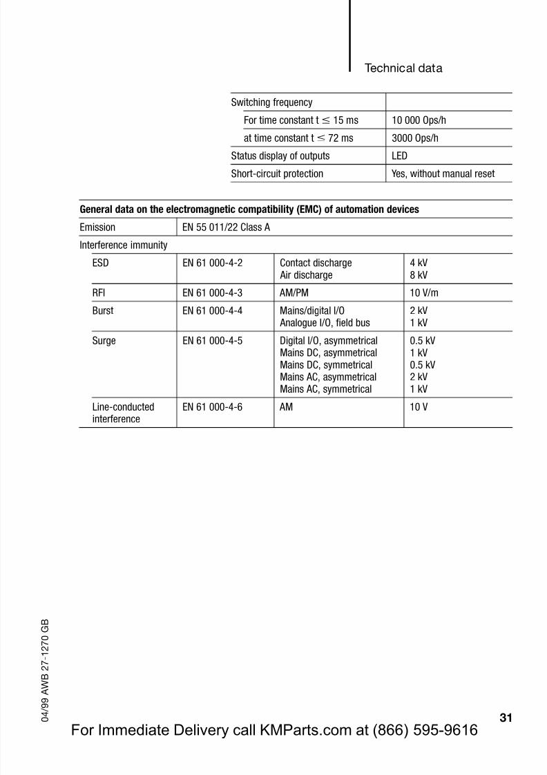
Switching frequency
For time constant t 15 ms 10 000 Ops/h
at time constant t 72 ms 3000 Ops/h
Status display of outputs LED
Short-circuit protection Yes, without manual reset
General data on the electromagnetic compatibility (EMC) of automation devices
Emission EN 55 011/22 Class A
Interference immunity
ESD EN 61 000-4-2 Contact discharge Air discharge 4 kV8 kV
RFI EN 61 000-4-3 AM/PM 10 V/m
Burst EN 61 000-4-4 Mains/digital I/O Analogue I/O, field bus
2 kV1 kV
Surge EN 61 000-4-5 Digital I/O, asymmetricalMains DC, asymmetricalMains DC, symmetricalMains AC, asymmetricalMains AC, symmetrical
0.5 kV1 kV0.5 kV2 kV1 kV
Line-conductedinterference
EN 61 000-4-6 AM 10 V
For Immediate Delivery call KMParts.com at (866) 595-9616
Page 35
8/3/2019 MODULOS FAMILIA MOELLER
http://slidepdf.com/reader/full/modulos-familia-moeller 35/61
Page 36
8/3/2019 MODULOS FAMILIA MOELLER
http://slidepdf.com/reader/full/modulos-familia-moeller 36/61
33 0 4 / 9 9 A W B 2 7 - 1 2 7 0 G B
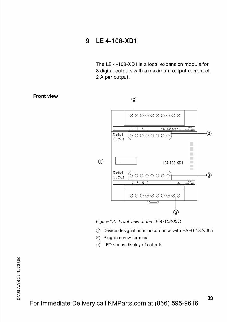
9 LE 4-108-XD1
The LE 4-108-XD1 is a local expansion module for8 digital outputs with a maximum output current of2 A per output.
Front view
Figure 13: Front view of the LE 4-108-XD1
Device designation in accordance with HAEG 18 6.5
Plug-in screw terminal
LED status display of outputs
LE4-108-XD1
.0 .1 .2 .3
.4 .5 .6 .7 0V
DigitalOutput
DigitalOutput
OutputPower Supply
24V 24V 24V 24VOutput
Power Supply
For Immediate Delivery call KMParts.com at (866) 595-9616
Page 37
8/3/2019 MODULOS FAMILIA MOELLER
http://slidepdf.com/reader/full/modulos-familia-moeller 37/61
LE 4-108-XD1
34 0 4 / 9 9 A W B 2 7 - 1 2 7 0 G B
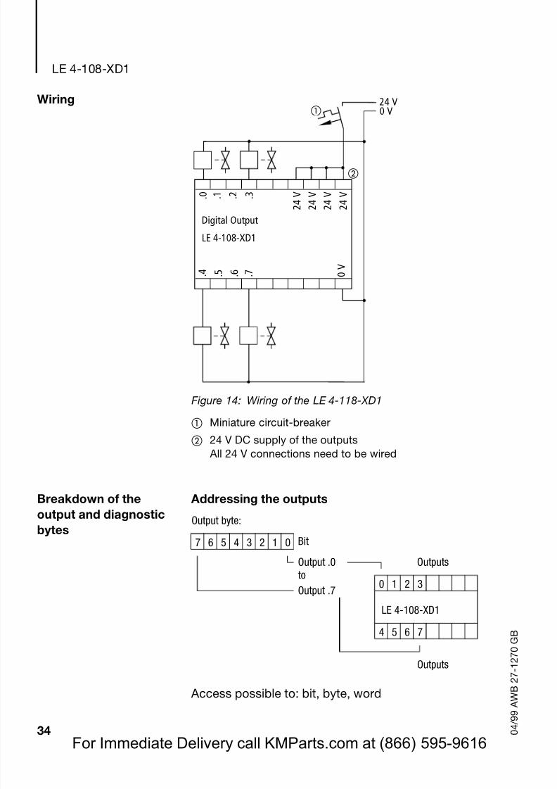
Wiring
Figure 14: Wiring of the LE 4-118-XD1
Miniature circuit-breaker
24 V DC supply of the outputs All 24 V connections need to be wired
Breakdown of theoutput and diagnosticbytes
Addressing the outputs
Access possible to: bit, byte, word
0 V
2 4 V
LE 4-108-XD1
24 V0 V
. 5 . 6 . 7 . 4
. 0 . 1 . 2 . 3
Digital Output 2 4 V
2 4 V
2 4 V
Output byte:
7 6 5 4 3 2 1 0 BitOutput .0 Outputsto
0 1 2 3Output .7
LE 4-108-XD1
4 5 6 7
Outputs
For Immediate Delivery call KMParts.com at (866) 595-9616
Page 38
8/3/2019 MODULOS FAMILIA MOELLER
http://slidepdf.com/reader/full/modulos-familia-moeller 38/61
Technical data
35 0 4 / 9 9 A W B 2 7 - 1 2 7 0 G B
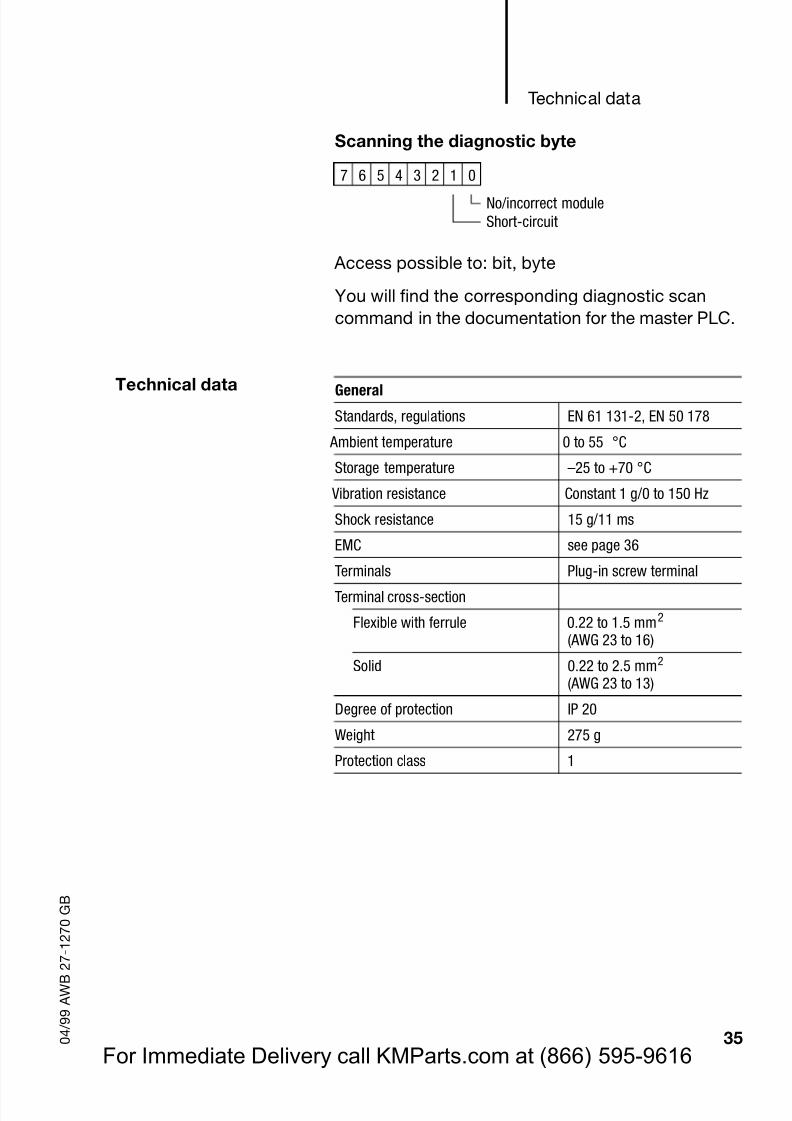
Scanning the diagnostic byte
Access possible to: bit, byte
You will find the corresponding diagnostic scancommand in the documentation for the master PLC.
Technical data
7 6 5 4 3 2 1 0
No/incorrect moduleShort-circuit
General
Standards, regulations EN 61 131-2, EN 50 178
Ambient temperature 0 to 55 °C
Storage temperature –25 to +70 °C
Vibration resistance Constant 1 g/0 to 150 Hz
Shock resistance 15 g/11 ms
EMC seepage 36
Terminals Plug-in screw terminalTerminal cross-section
Flexible with ferrule 0.22 to 1.5 mm2
(AWG 23 to 16)
Solid 0.22 to 2.5 mm2
(AWG 23 to 13)
Degree of protection IP 20
Weight 275 g
Protection class 1
For Immediate Delivery call KMParts.com at (866) 595-9616
Page 39
8/3/2019 MODULOS FAMILIA MOELLER
http://slidepdf.com/reader/full/modulos-familia-moeller 39/61
LE 4-108-XD1
36 0 4 / 9 9 A W B 2 7 - 1 2 7 0 G B
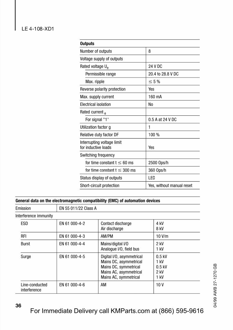
Outputs
Number of outputs 8
Voltage supply of outputs
Rated voltage Ue 24 V DC
Permissible range 20.4 to 28.8 V DC
Max. ripple 5 %
Reverse polarity protection Yes
Max. supply current 160 mA
Electrical isolation No
Rated current eFor signal "1" 0.5 A at 24 V DC
Utilization factor g 1
Relative duty factor DF 100 %
Interrupting voltage limitfor inductive loads Yes
Switching frequency
for time constant t 60 ms 2500 Ops/h
for time constant t 300 ms 360 Ops/hStatus display of outputs LED
Short-circuit protection Yes, without manual reset
General data on the electromagnetic compatibility (EMC) of automation devices
Emission EN 55 011/22 Class A
Interference immunity
ESD EN 61 000-4-2 Contact discharge Air discharge
4 kV8 kV
RFI EN 61 000-4-3 AM/PM 10 V/m
Burst EN 61 000-4-4 Mains/digital I/O Analogue I/O, field bus
2 kV1 kV
Surge EN 61 000-4-5 Digital I/O, asymmetricalMains DC, asymmetricalMains DC, symmetricalMains AC, asymmetricalMains AC, symmetrical
0.5 kV1 kV0.5 kV2 kV1 kV
Line-conductedinterference
EN 61 000-4-6 AM 10 V
For Immediate Delivery call KMParts.com at (866) 595-9616
Page 40
8/3/2019 MODULOS FAMILIA MOELLER
http://slidepdf.com/reader/full/modulos-familia-moeller 40/61
37 0 4 / 9 9 A W B 2 7 - 1 2 7 0 G B
10 LE 4-108-XR1
The LE 4-108-XR1 is a local expansion module for8 relay outputs.
Front view
Figure 15: Front view of the LE 4-108-XR1
Device designation in accordance with HAEG 18 6.5
Plug-in screw terminal
LED status display of outputs
LE4-108-XR1
0V
RelaisOutput
RelaisOutputRelais
Power Supply
24V RelaisPower Supply.0C0 C1 C2 C3.1 .2 .3
.4C4 C5 C6 C7.5 .6 .7
For Immediate Delivery call KMParts.com at (866) 595-9616
Page 41
8/3/2019 MODULOS FAMILIA MOELLER
http://slidepdf.com/reader/full/modulos-familia-moeller 41/61
LE 4-108-XR1
38 0 4 / 9 9 A W B 2 7 - 1 2 7 0 G B
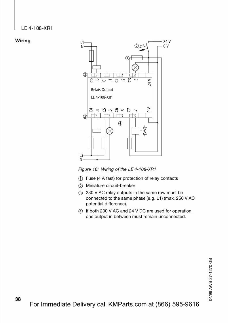
Wiring
Figure 16: Wiring of the LE 4-108-XR1
Fuse (4 A fast) for protection of relay contacts
Miniature circuit-breaker
230 V AC relay outputs in the same row must beconnected to the same phase (e.g. L1) (max. 250 V ACpotential difference).
If both 230 V AC and 24 V DC are used for operation,one output in between must remain unconnected.
0
V
2 4 V
LE 4-108-XR1
24 V0 V
L1
. 5 . 6 . 7 . 4
. 0 . 1 . 2 . 3
N
L3N
Relais Output
C 0
C 1
C 2
C 3
C 4
C 5
C 6
C 7
For Immediate Delivery call KMParts.com at (866) 595-9616
Page 42
8/3/2019 MODULOS FAMILIA MOELLER
http://slidepdf.com/reader/full/modulos-familia-moeller 42/61
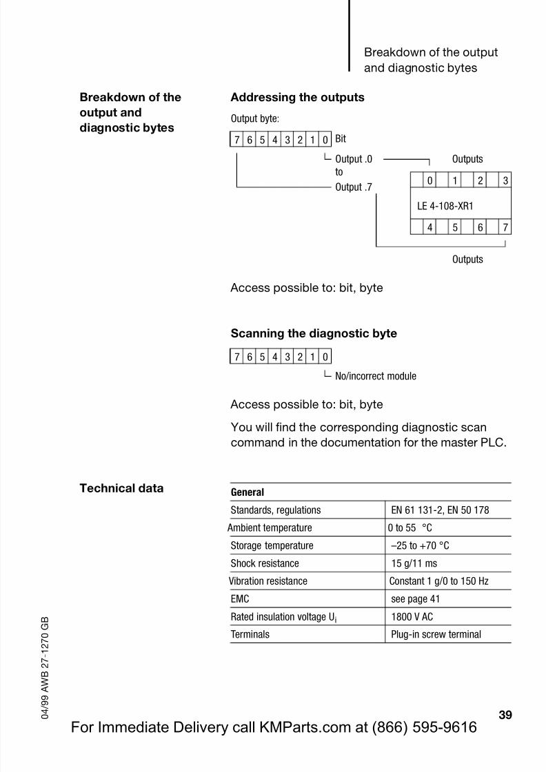
Breakdown of the outputand diagnostic bytes
39 0 4 / 9 9 A W B 2 7 - 1 2 7 0 G B
Breakdown of theoutput and
diagnostic bytes
Addressing the outputs
Access possible to: bit, byte
Scanning the diagnostic byte
Access possible to: bit, byte
You will find the corresponding diagnostic scancommand in the documentation for the master PLC.
Technical data
Output byte:
7 6 5 4 3 2 1 0 Bit
Output .0 Outputsto
0 1 2 3Output .7
LE 4-108-XR1
4 5 6 7
Outputs
7 6 5 4 3 2 1 0
No/incorrect module
General
Standards, regulations EN 61 131-2, EN 50 178
Ambient temperature 0 to 55 °CStorage temperature –25 to +70 °C
Shock resistance 15 g/11 ms
Vibration resistance Constant 1 g/0 to 150 Hz
EMC seepage 41
Rated insulation voltage Ui 1800 V AC
Terminals Plug-in screw terminal
For Immediate Delivery call KMParts.com at (866) 595-9616
Page 43
8/3/2019 MODULOS FAMILIA MOELLER
http://slidepdf.com/reader/full/modulos-familia-moeller 43/61
LE 4-108-XR1
40 0 4 / 9 9 A W B 2 7 - 1 2 7 0 G B
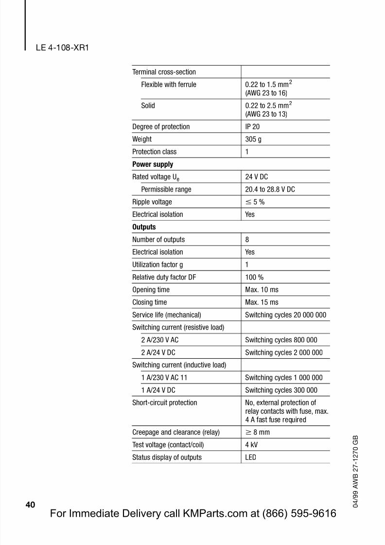
Terminal cross-section
Flexible with ferrule 0.22 to 1.5 mm2
(AWG 23 to 16)Solid 0.22 to 2.5 mm2
(AWG 23 to 13)
Degree of protection IP 20
Weight 305 g
Protection class 1
Power supply
Rated voltage Ue 24 V DC
Permissible range 20.4 to 28.8 V DC
Ripple voltage 5 %
Electrical isolation Yes
Outputs
Number of outputs 8
Electrical isolation Yes
Utilization factor g 1
Relative duty factor DF 100 %
Opening time Max. 10 ms
Closing time Max. 15 ms
Service life (mechanical) Switching cycles 20 000 000
Switching current (resistive load)
2 A/230 V AC Switching cycles 800 000
2 A/24 V DC Switching cycles 2 000 000
Switching current (inductive load)
1 A/230 V AC 11 Switching cycles 1 000 000
1 A/24 V DC Switching cycles 300 000
Short-circuit protection No, external protection ofrelay contacts with fuse, max.4 A fast fuse required
Creepage and clearance (relay) 8 mm
Test voltage (contact/coil) 4 kV
Status display of outputs LED
For Immediate Delivery call KMParts.com at (866) 595-9616
Page 44
8/3/2019 MODULOS FAMILIA MOELLER
http://slidepdf.com/reader/full/modulos-familia-moeller 44/61
Technical data
41 0 4 / 9 9 A W B 2 7 - 1 2 7 0 G B
General data on the electromagnetic compatibility (EMC) of automation devices
Emission EN 55 011/22 Class A
Interference immunity
ESD EN 61 000-4-2 Contact discharge Air discharge
4 kV8 kV
RFI EN 61 000-4-3 AM/PM 10 V/m
Burst EN 61 000-4-4 Mains/digital I/O Analogue I/O, field bus
2 kV1 kV
Surge EN 61 000-4-5 Digital I/O, asymmetricalMains DC, asymmetricalMains DC, symmetricalMains AC, asymmetricalMains AC, symmetrical
0.5 kV1 kV0.5 kV2 kV1 kV
Line-conductedinterference
EN 61 000-4-6 AM 10 V
For Immediate Delivery call KMParts.com at (866) 595-9616
Page 45
8/3/2019 MODULOS FAMILIA MOELLER
http://slidepdf.com/reader/full/modulos-familia-moeller 45/61
42 0 4 / 9 9 A W B 2 7 - 1 2 7 0 G B
For Immediate Delivery call KMParts.com at (866) 595-9616
Page 46
8/3/2019 MODULOS FAMILIA MOELLER
http://slidepdf.com/reader/full/modulos-familia-moeller 46/61
43 0 4 / 9 9 A W B 2 7 - 1 2 7 0 G B
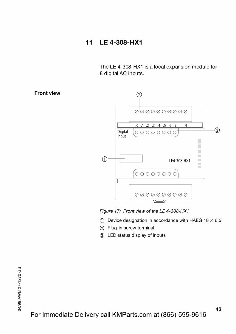
11 LE 4-308-HX1
The LE 4-308-HX1 is a local expansion module for8 digital AC inputs.
Front view
Figure 17: Front view of the LE 4-308-HX1
Device designation in accordance with HAEG 18 6.5
Plug-in screw terminalLED status display of inputs
LE4-308-HX1
.0 .1 .2 .3 .4 .5 .6 .7 N
DigitalInput
For Immediate Delivery call KMParts.com at (866) 595-9616
Page 47
8/3/2019 MODULOS FAMILIA MOELLER
http://slidepdf.com/reader/full/modulos-familia-moeller 47/61
LE 4-308-HX1
44 0 4 / 9 9 A W B 2 7 - 1 2 7 0 G B
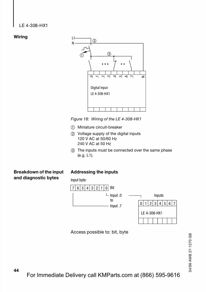
Wiring
Figure 18: Wiring of the LE 4-308-HX1
Miniature circuit-breaker
Voltage supply of the digital inputs120 V AC at 50/60 Hz240 V AC at 50 Hz
The inputs must be connected over the same phase(e.g. L1).
Breakdown of the inputand diagnostic bytes
Addressing the inputs
Access possible to: bit, byte
L1N
. 0 . 1 . 7 . 2 . 3 . 4 . 5 . 6
Digital Input
LE 4-308-HX1
N
Input byte:
7 6 5 4 3 2 1 0 Bit
Input .0 Inputs
to 0 1 2 3 4 5 6 7Input .7
LE 4-308-HX1
For Immediate Delivery call KMParts.com at (866) 595-9616
Page 48
8/3/2019 MODULOS FAMILIA MOELLER
http://slidepdf.com/reader/full/modulos-familia-moeller 48/61
Technical data
45 0 4 / 9 9 A W B 2 7 - 1 2 7 0 G B
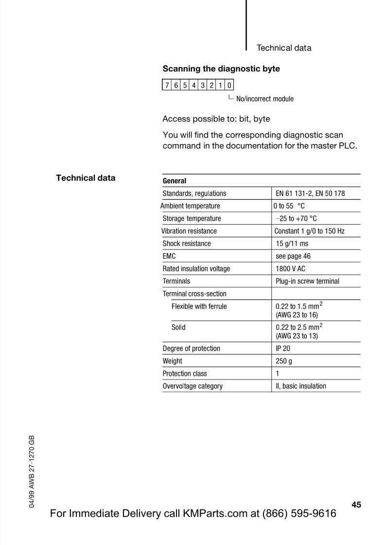
Scanning the diagnostic byte
Access possible to: bit, byte
You will find the corresponding diagnostic scancommand in the documentation for the master PLC.
Technical data
7 6 5 4 3 2 1 0
No/incorrect module
General
Standards, regulations EN 61 131-2, EN 50 178
Ambient temperature 0 to 55 °C
Storage temperature –25 to +70 °C
Vibration resistance Constant 1 g/0 to 150 Hz
Shock resistance 15 g/11 ms
EMC seepage 46
Rated insulation voltage 1800 V AC
Terminals Plug-in screw terminalTerminal cross-section
Flexible with ferrule 0.22 to 1.5 mm2
(AWG 23 to 16)
Solid 0.22 to 2.5 mm2
(AWG 23 to 13)
Degree of protection IP 20
Weight 250 g
Protection class 1Overvoltage category II, basic insulation
For Immediate Delivery call KMParts.com at (866) 595-9616
Page 49
8/3/2019 MODULOS FAMILIA MOELLER
http://slidepdf.com/reader/full/modulos-familia-moeller 49/61
LE 4-308-HX1
46 0 4 / 9 9 A W B 2 7 - 1 2 7 0 G B
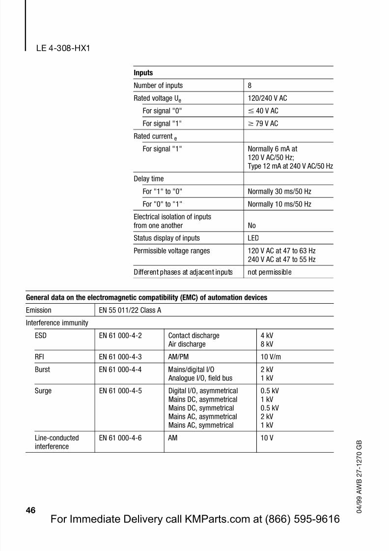
Inputs
Number of inputs 8
Rated voltage Ue 120/240 V AC
For signal "0" 40 V AC
For signal "1" 79 V AC
Rated current e
For signal "1" Normally 6 mA at120 V AC/50 Hz;Type 12 mA at 240 V AC/50 Hz
Delay time
For "1" to "0" Normally 30 ms/50 Hz
For "0" to "1" Normally 10 ms/50 Hz
Electrical isolation of inputsfrom one another No
Status display of inputs LED
Permissible voltage ranges 120 V AC at 47 to 63 Hz240 V AC at 47 to 55 Hz
Different phases at adjacent inputs not permissible
General data on the electromagnetic compatibility (EMC) of automation devices
Emission EN 55 011/22 Class A
Interference immunity
ESD EN 61 000-4-2 Contact discharge Air discharge
4 kV8 kV
RFI EN 61 000-4-3 AM/PM 10 V/m
Burst EN 61 000-4-4 Mains/digital I/O
Analogue I/O, field bus
2 kV
1 kVSurge EN 61 000-4-5 Digital I/O, asymmetrical
Mains DC, asymmetricalMains DC, symmetricalMains AC, asymmetricalMains AC, symmetrical
0.5 kV1 kV0.5 kV2 kV1 kV
Line-conductedinterference
EN 61 000-4-6 AM 10 V
For Immediate Delivery call KMParts.com at (866) 595-9616
Page 50
8/3/2019 MODULOS FAMILIA MOELLER
http://slidepdf.com/reader/full/modulos-familia-moeller 50/61
47 0 4 / 9 9 A W B 2 7 - 1 2 7 0 G B
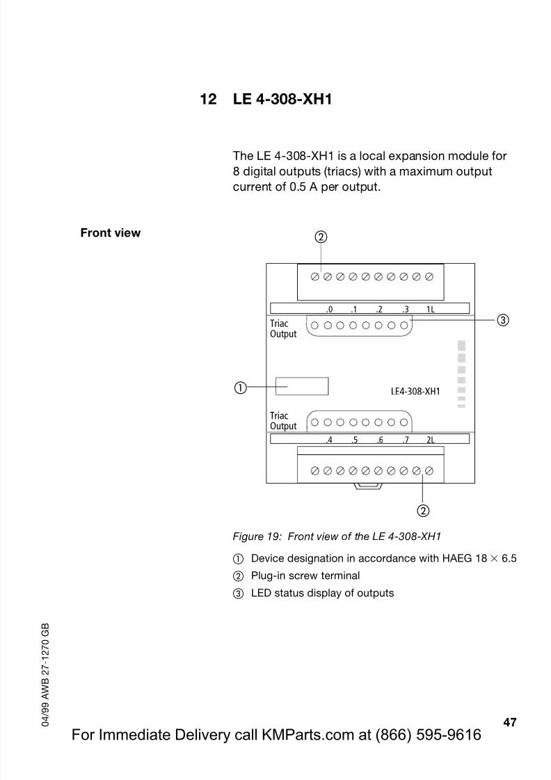
12 LE 4-308-XH1
The LE 4-308-XH1 is a local expansion module for8 digital outputs (triacs) with a maximum outputcurrent of 0.5 A per output.
Front view
Figure 19: Front view of the LE 4-308-XH1
Device designation in accordance with HAEG 18 6.5
Plug-in screw terminal
LED status display of outputs
LE4-308-XH1
.0 .1 .2 .3 1L
.4 .5 .6 .7 2L
TriacOutput
TriacOutput
For Immediate Delivery call KMParts.com at (866) 595-9616
Page 51
8/3/2019 MODULOS FAMILIA MOELLER
http://slidepdf.com/reader/full/modulos-familia-moeller 51/61
LE 4-308-XH1
48 0 4 / 9 9 A W B 2 7 - 1 2 7 0 G B
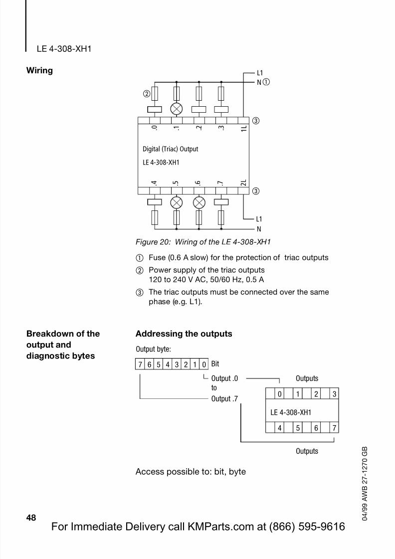
Wiring
Figure 20: Wiring of the LE 4-308-XH1
Fuse (0.6 A slow) for the protection of triac outputs
Power supply of the triac outputs120 to 240 V AC, 50/60 Hz, 0.5 A
The triac outputs must be connected over the samephase (e.g. L1).
Breakdown of theoutput anddiagnostic bytes
Addressing the outputs
Access possible to: bit, byte
. 0 . 1 . 2 . 3
. 7 2 L
. 4 . 5 . 6
LE 4-308-XH1
1 L
NL1
NL1
Digital (Triac) Output
Output byte:
7 6 5 4 3 2 1 0 Bit
Output .0 Outputsto
0 1 2 3Output .7
LE 4-308-XH1
4 5 6 7
Outputs
For Immediate Delivery call KMParts.com at (866) 595-9616
Page 52
8/3/2019 MODULOS FAMILIA MOELLER
http://slidepdf.com/reader/full/modulos-familia-moeller 52/61
Page 53
8/3/2019 MODULOS FAMILIA MOELLER
http://slidepdf.com/reader/full/modulos-familia-moeller 53/61
LE 4-308-XH1
50 0 4 / 9 9 A W B 2 7 - 1 2 7 0 G B
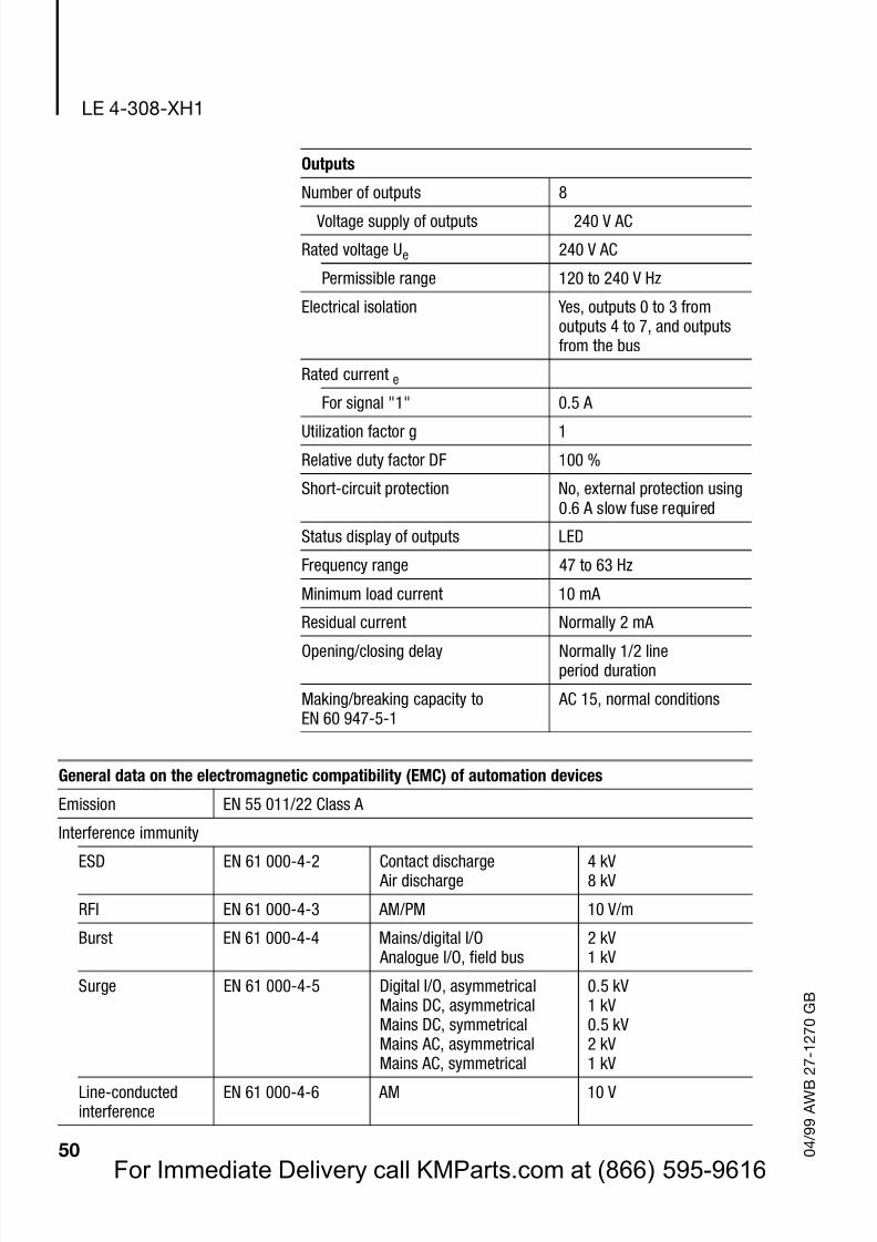
Outputs
Number of outputs 8
Voltage supply of outputs 240 V AC
Rated voltage Ue 240 V AC
Permissible range 120 to 240 V Hz
Electrical isolation Yes, outputs 0 to 3 fromoutputs 4 to 7, and outputsfrom the bus
Rated current e
For signal "1" 0.5 A
Utilization factor g 1
Relative duty factor DF 100 %
Short-circuit protection No, external protection using0.6 A slow fuse required
Status display of outputs LED
Frequency range 47 to 63 Hz
Minimum load current 10 mA
Residual current Normally 2 mA
Opening/closing delay Normally 1/2 lineperiod duration
Making/breaking capacity toEN 60 947-5-1
AC 15, normal conditions
General data on the electromagnetic compatibility (EMC) of automation devices
Emission EN 55 011/22 Class A
Interference immunity
ESD EN 61 000-4-2 Contact discharge Air discharge
4 kV8 kV
RFI EN 61 000-4-3 AM/PM 10 V/m
Burst EN 61 000-4-4 Mains/digital I/O Analogue I/O, field bus
2 kV1 kV
Surge EN 61 000-4-5 Digital I/O, asymmetricalMains DC, asymmetricalMains DC, symmetricalMains AC, asymmetrical
Mains AC, symmetrical
0.5 kV1 kV0.5 kV2 kV
1 kVLine-conductedinterference
EN 61 000-4-6 AM 10 V
For Immediate Delivery call KMParts.com at (866) 595-9616
Page 54
8/3/2019 MODULOS FAMILIA MOELLER
http://slidepdf.com/reader/full/modulos-familia-moeller 54/61
51 0 4 / 9 9 A W B 2 7 - 1 2 7 0 G B
13 LE 4-104-XP1
Pneumatics A pneumatic output stage is integrated in theLE 4-104-XP1. This is a valve block with four micromagnetic valves (MMVs) with central connection forthe compressed air supply and ventilation. The four3/2-way valves are directly controlled in the ZCfunction (ZC = zero position closed). Due to the jointpressure connection in the connection base of the
valve block, the valves of an LE 4-104-XP1 can onlybe operated with the same supply pressure.
No tools are required to connect the PE hose and thevalve block. The hose is fitted over the hose nipplemanually.
! When installign the LE 4-104-XP1 in a controlcabinet, the ventilation cable must be routed outof the cabinet.
For Immediate Delivery call KMParts.com at (866) 595-9616
Page 55
8/3/2019 MODULOS FAMILIA MOELLER
http://slidepdf.com/reader/full/modulos-familia-moeller 55/61
LE 4-104-XP1
52 0 4 / 9 9 A W B 2 7 - 1 2 7 0 G B
Front view
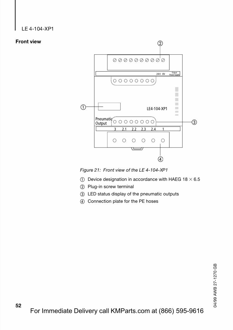
Figure 21: Front view of the LE 4-104-XP1
Device designation in accordance with HAEG 18 6.5
Plug-in screw terminal
LED status display of the pneumatic outputs
Connection plate for the PE hoses
LE4-104-XP1
24V 0V OutputPower Supply
3 2.1 2.2 2.3 2.4 1
PneumaticOutput
For Immediate Delivery call KMParts.com at (866) 595-9616
Page 56
8/3/2019 MODULOS FAMILIA MOELLER
http://slidepdf.com/reader/full/modulos-familia-moeller 56/61
Wiring
53 0 4 / 9 9 A W B 2 7 - 1 2 7 0 G B
Wiring
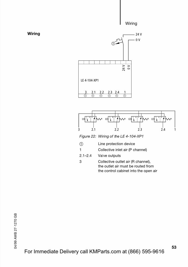
Figure 22: Wiring of the LE 4-104-XP1Line protection device
1 Collective inlet air (P channel)
2.1 –2.4 Valve outputs
3 Collective outlet air (R channel),the outlet air must be routed fromthe control cabinet into the open air
0 V
2 4 V
LE 4-104-XP1
24 V
0 V
3 2.1 2.2 2.3 2.4 1
3 2.1 2.2 2.3 2.4 1
For Immediate Delivery call KMParts.com at (866) 595-9616
Page 57
8/3/2019 MODULOS FAMILIA MOELLER
http://slidepdf.com/reader/full/modulos-familia-moeller 57/61
LE 4-104-XP1
54 0 4 / 9 9 A W B 2 7 - 1 2 7 0 G B
Breakdown of theoutput and
diagnostic bytes
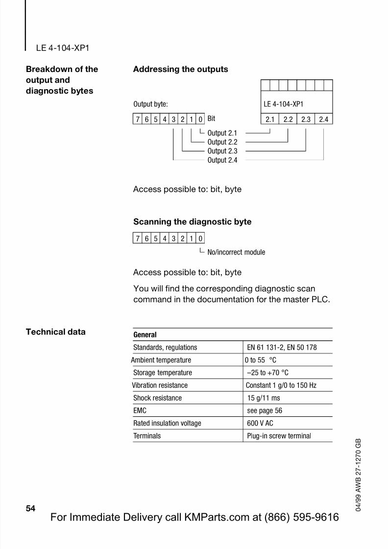
Addressing the outputs
Access possible to: bit, byte
Scanning the diagnostic byte
Access possible to: bit, byte
You will find the corresponding diagnostic scancommand in the documentation for the master PLC.
Technical data
Output byte: LE 4-104-XP1
7 6 5 4 3 2 1 0 Bit 2.1 2.2 2.3 2.4
Output 2.1Output 2.2Output 2.3Output 2.4
7 6 5 4 3 2 1 0
No/incorrect module
General
Standards, regulations EN 61 131-2, EN 50 178
Ambient temperature 0 to 55 °C
Storage temperature –25 to +70 °C
Vibration resistance Constant 1 g/0 to 150 Hz
Shock resistance 15 g/11 ms
EMC seepage 56
Rated insulation voltage 600 V AC
Terminals Plug-in screw terminal
For Immediate Delivery call KMParts.com at (866) 595-9616
Page 58
8/3/2019 MODULOS FAMILIA MOELLER
http://slidepdf.com/reader/full/modulos-familia-moeller 58/61
Technical data
55 0 4 / 9 9 A W B 2 7 - 1 2 7 0 G B
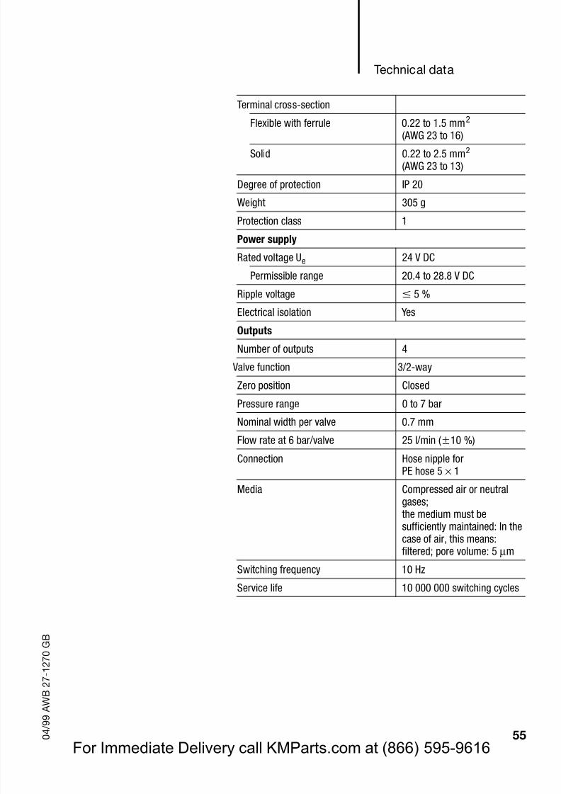
Terminal cross-section
Flexible with ferrule 0.22 to 1.5 mm2
(AWG 23 to 16)Solid 0.22 to 2.5 mm2
(AWG 23 to 13)
Degree of protection IP 20
Weight 305 g
Protection class 1
Power supply
Rated voltage Ue 24 V DC
Permissible range 20.4 to 28.8 V DC
Ripple voltage 5 %
Electrical isolation Yes
Outputs
Number of outputs 4
Valve function 3/2-way
Zero position Closed
Pressure range 0 to 7 bar
Nominal width per valve 0.7 mm
Flow rate at 6 bar/valve 25 l/min ( 10 %)
Connection Hose nipple forPE hose 5 × 1
Media Compressed air or neutralgases;the medium must besufficiently maintained: In thecase of air, this means:filtered; pore volume: 5 µ m
Switching frequency 10 Hz
Service life 10 000 000 switching cycles
For Immediate Delivery call KMParts.com at (866) 595-9616
Page 59
8/3/2019 MODULOS FAMILIA MOELLER
http://slidepdf.com/reader/full/modulos-familia-moeller 59/61
LE 4-104-XP1
56 0 4 / 9 9 A W B 2 7 - 1 2 7 0 G B
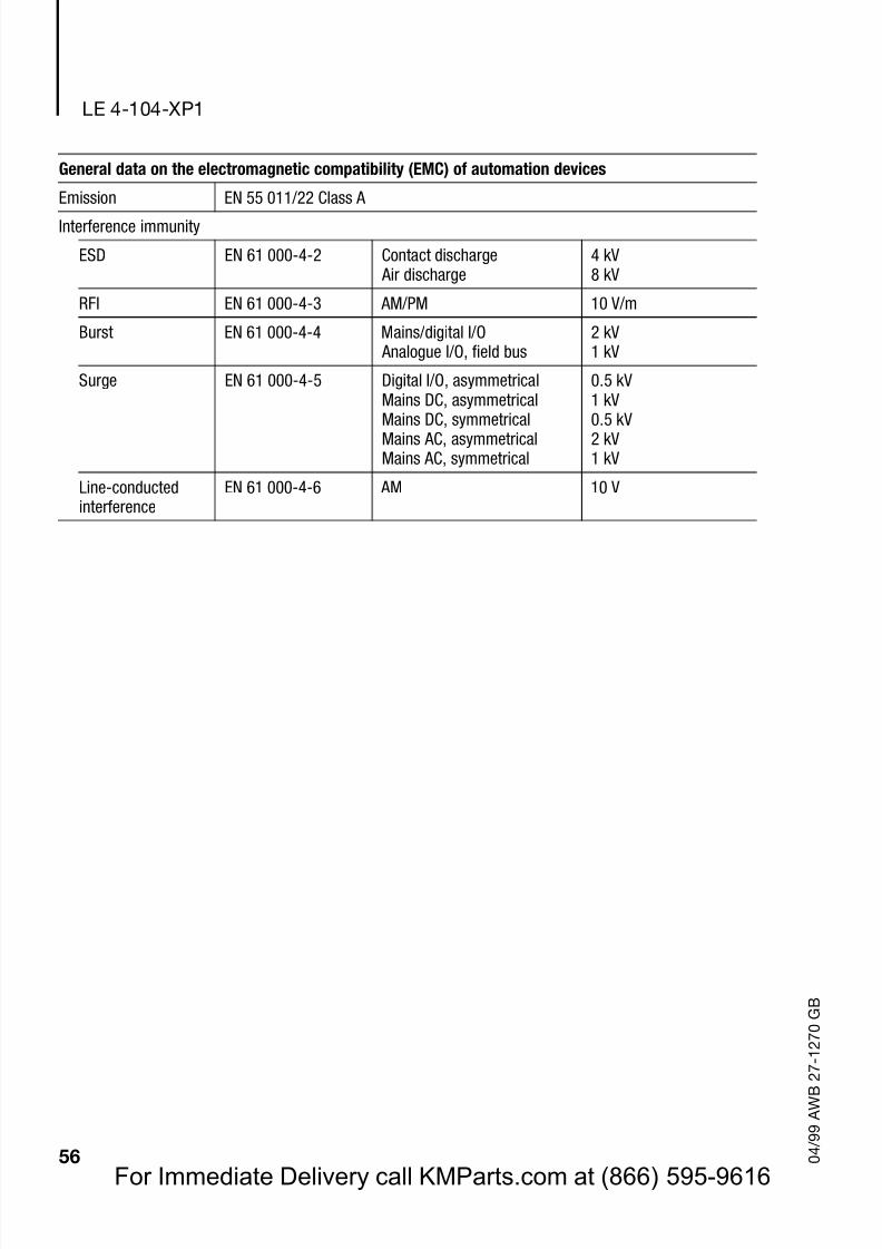
General data on the electromagnetic compatibility (EMC) of automation devices
Emission EN 55 011/22 Class A
Interference immunity
ESD EN 61 000-4-2 Contact discharge Air discharge
4 kV8 kV
RFI EN 61 000-4-3 AM/PM 10 V/m
Burst EN 61 000-4-4 Mains/digital I/O Analogue I/O, field bus
2 kV1 kV
Surge EN 61 000-4-5 Digital I/O, asymmetricalMains DC, asymmetricalMains DC, symmetricalMains AC, asymmetricalMains AC, symmetrical
0.5 kV1 kV0.5 kV2 kV1 kV
Line-conductedinterference
EN 61 000-4-6 AM 10 V
For Immediate Delivery call KMParts.com at (866) 595-9616
Page 60
8/3/2019 MODULOS FAMILIA MOELLER
http://slidepdf.com/reader/full/modulos-familia-moeller 60/61
57 0 4 / 9 9 A W B 2 7 - 1 2 7 0 G B
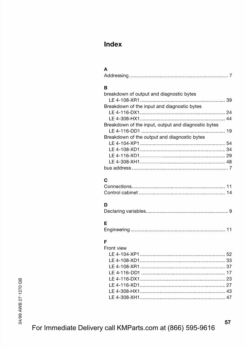
Index
A Addressing........................................................................ 7
Bbreakdown of output and diagnostic bytes
LE 4-108-XR1.............................................................. 39Breakdown of the input and diagnostic bytes
LE 4-116-DX1.............................................................. 24
LE 4-308-HX1.............................................................. 44Breakdown of the input, output and diagnostic bytes
LE 4-116-DD1 ............................................................. 19Breakdown of the output and diagnostic bytes
LE 4-104-XP1.............................................................. 54LE 4-108-XD1.............................................................. 34LE 4-116-XD1.............................................................. 29LE 4-308-XH1.............................................................. 48
bus address ...................................................................... 7
CConnections.................................................................... 11Control cabinet ............................................................... 14
DDeclaring variables............................................................ 9
EEngineering ..................................................................... 11
FFront view
LE 4-104-XP1.............................................................. 52LE 4-108-XD1.............................................................. 33LE 4-108-XR1.............................................................. 37LE 4-116-DD1 ............................................................. 17LE 4-116-DX1.............................................................. 23LE 4-116-XD1.............................................................. 27LE 4-308-HX1.............................................................. 43
LE 4-308-XH1.............................................................. 47
For Immediate Delivery call KMParts.com at (866) 595-9616
Page 61
8/3/2019 MODULOS FAMILIA MOELLER
http://slidepdf.com/reader/full/modulos-familia-moeller 61/61
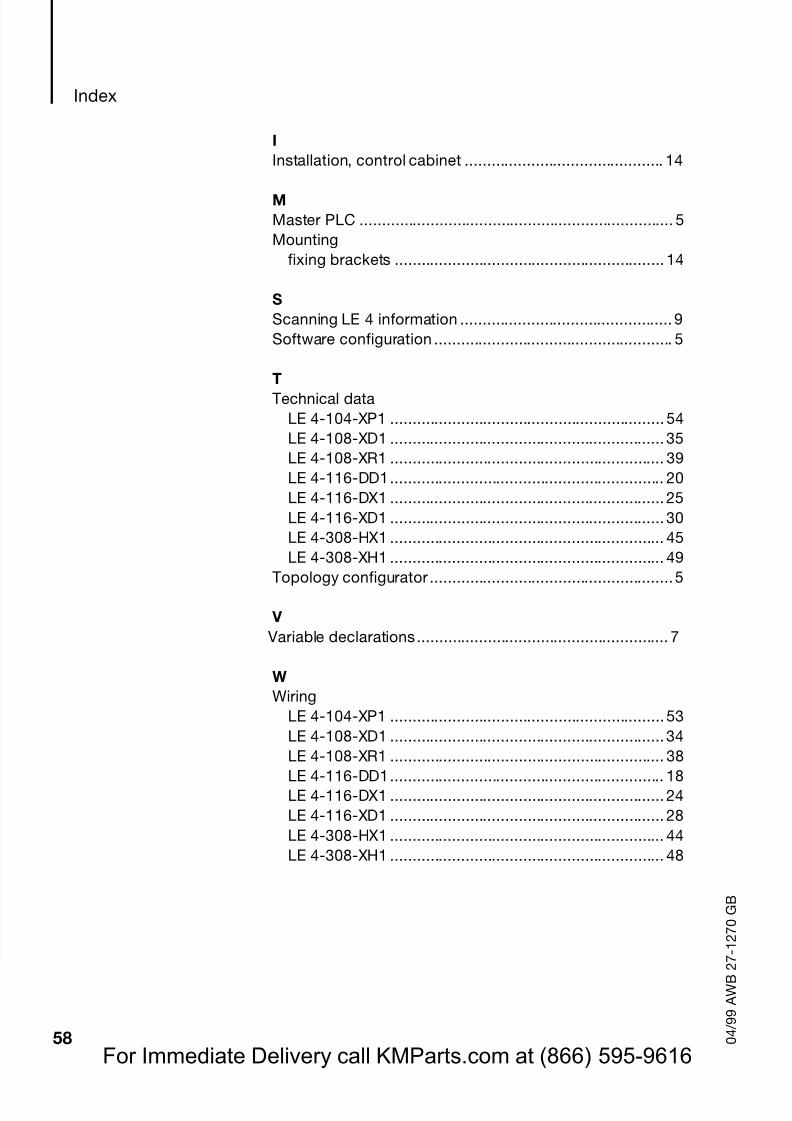
Index
IInstallation, control cabinet ............................................. 14
MMaster PLC ....................................................................... 5Mounting
fixing brackets ............................................................. 14
SScanning LE 4 information ................................................ 9Software configuration ...................................................... 5
TTechnical dataLE 4-104-XP1 .............................................................. 54LE 4-108-XD1 .............................................................. 35LE 4-108-XR1 .............................................................. 39LE 4-116-DD1.............................................................. 20LE 4-116-DX1 .............................................................. 25LE 4-116-XD1 .............................................................. 30LE 4-308-HX1 .............................................................. 45LE 4-308-XH1 .............................................................. 49
Topology configurator ....................................................... 5
V Variable declarations......................................................... 7
WWiring
LE 4-104-XP1 .............................................................. 53LE 4-108-XD1 .............................................................. 34LE 4-108-XR1 .............................................................. 38LE 4-116-DD1.............................................................. 18LE 4-116-DX1 .............................................................. 24LE 4-116-XD1 .............................................................. 28LE 4-308-HX1 .............................................................. 44LE 4-308-XH1 .............................................................. 48