4
TYPCorrection Factor of Operating Pressure
Technical Specification
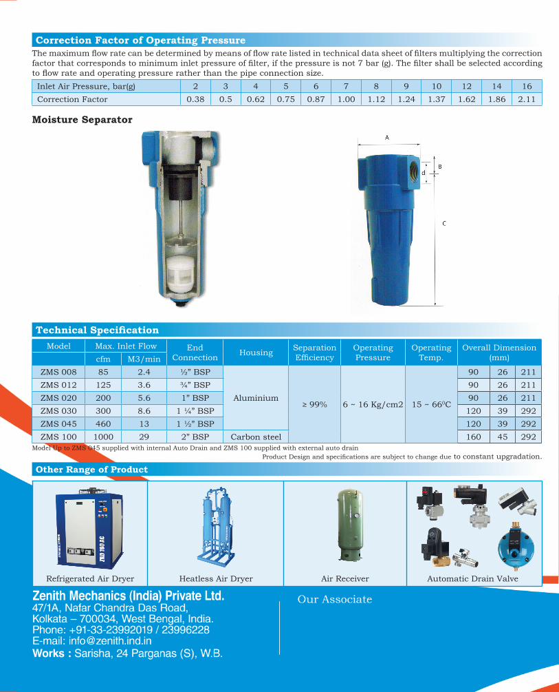
The maximum flow rate can be determined by means of flow rate listed in technical data sheet of filters multiplying the correction factor that corresponds to minimum inlet pressure of filter, if the pressure is not 7 bar (g). The filter shall be selected according to flow rate and operating pressure rather than the pipe connection size. Inlet Air Pressure, bar(g) 2 3 4 5 6 7 8 9 10 12 14 16Correction Factor 0.38 0.5 0.62 0.75 0.87 1.00 1.12 1.24 1.37 1.62 1.86 2.11
Model Max. Inlet Flow End Connection Housing Separation
EfficiencyOperating Pressure
Operating Temp.
Overall Dimension (mm)cfm M3/min
ZMS 008 85 2.4 ½” BSP
Aluminium≥ 99% 6 ~ 16 Kg/cm2 15 ~ 660C
90 26 211ZMS 012 125 3.6 ¾” BSP 90 26 211ZMS 020 200 5.6 1” BSP 90 26 211ZMS 030 300 8.6 1 ¼” BSP 120 39 292ZMS 045 460 13 1 ½” BSP 120 39 292ZMS 100 1000 29 2” BSP Carbon steel 160 45 292
Model Up to ZMS 045 supplied with internal Auto Drain and ZMS 100 supplied with external auto drainProduct Design and specifications are subject to change due to constant upgradation.
Refrigerated Air Dryer Heatless Air Dryer Air Receiver Automatic Drain Valve
Other Range of Product
Moisture Separator
Compressed Air FilterPurification of compressed air is needed because the air we breathe carries contaminants. Airborne particles, water, microbes, and chemical gases enter compressors. At a compressed state these contaminants become concentrated and more destructive. In the compressed air system, hard particles assault equipment and piping. The result is damage to the system and more particles generated. Examples of particles found in a compressed air system include desiccant dust, rust, pipe scale, metal oxides, and dirt. By applying proper filtration system the above can be eliminated.
Features
Benefit
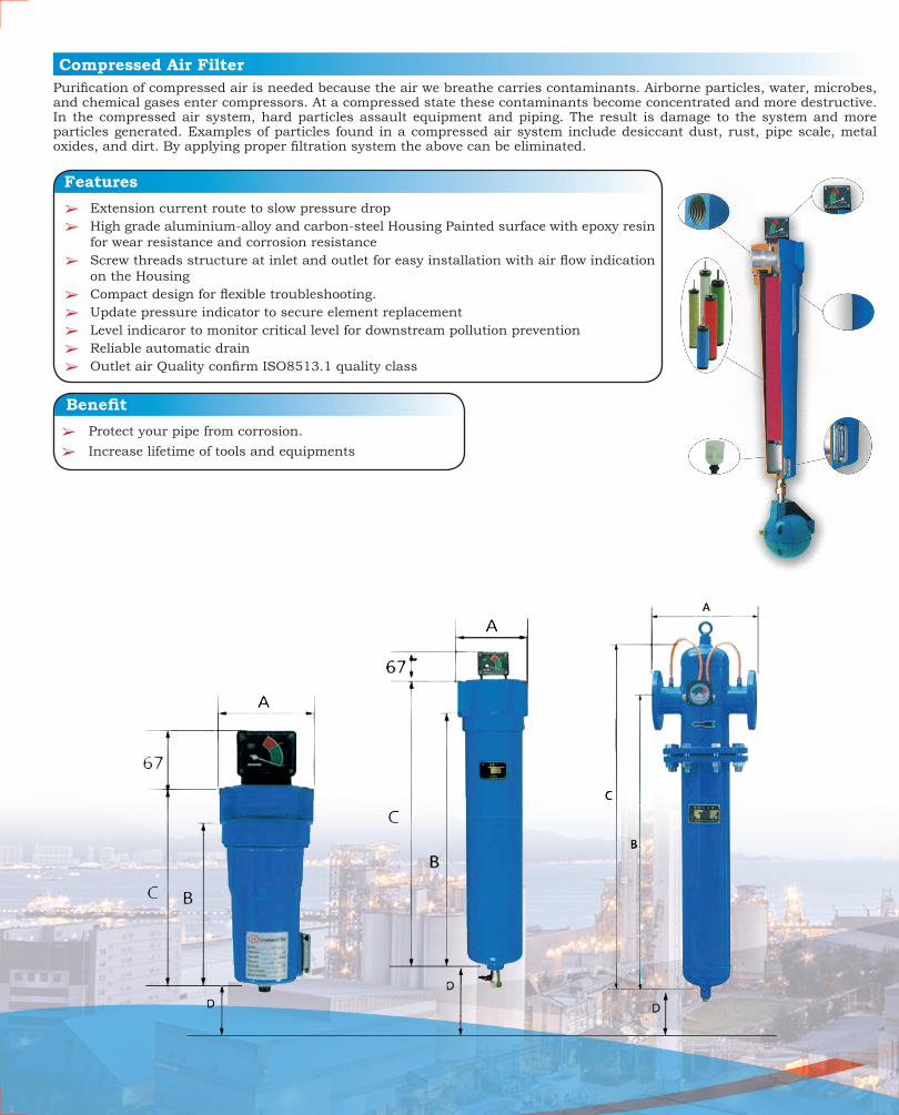
â Extension current route to slow pressure dropâ High grade aluminium-alloy and carbon-steel Housing Painted surface with epoxy resin
for wear resistance and corrosion resistanceâ Screw threads structure at inlet and outlet for easy installation with air flow indication
on the Housingâ Compact design for flexible troubleshooting.â Update pressure indicator to secure element replacementâ Level indicaror to monitor critical level for downstream pollution preventionâ Reliable automatic drainâ Outlet air Quality confirm ISO8513.1 quality class
â Protect your pipe from corrosion.â Increase lifetime of tools and equipments
PARTICULARSELEMENT TYPE
PRE FILTER AFTER FILTER OIL FILTER HYPER OIL FILTER
ACTIVATED CARBON FILTER
Element Grade P X Y H A
Media Boro Silicate Boro Silicate Boro Silicate Boro SilicateBoro Silicate
with impregnated Activated Carbon
Particle Removal 3 Micron 1 Micron 0.01 Micron 0.01 Micron 0.01 Micron
Residual Oil content 5mg/m3 1 mg/m3 0.01 mg/m3 0.001 mg/m3 0.001 mg/m3
Max. Working Temperature 800C
Nominal Initial Pressure Drop 0.03 bar (g) 0.05 bar (g) 0.06 bar (g) 0.06 bar (g) 0.12 bar (g)
Recommended Pressure Differential for element change 0.7 bar (g) 0.7 bar (g) 0.7 bar (g) 0.7 bar (g) 0.7 bar (g)
Efficiency 99% 99.9% 99.99% 99.999%
Application • Downstream position of after cooler.
• Upstream position of fine oil mist filter.
• Downstream position of absorption dryer.
• Dryer used directly in operation spot while cooler or separator is installed on upstream Position.
• Upstream position of adsorption dryer
• Downstream Position of refrigerated dryer
• Downstream position of Commutative pressure absorption dryer to eliminate fine Particles
• In operation spot
• Upstream position of absorption dryer, install a filter of grade T as a pre-filter if there is a large liquid load.
• Downstream Position of refrigerated dryer
• Downstream Position of super efficient fine oil mist filter
Note: Illustration/ Specification are subject to change without notice due to constant up gradation of products
Technical Specification
Element Specification
ModelModel Variant Inlet Flow
HousingStandard Accessories *
End Conn.Overall Dimension
P X Y H A cfm m3/Hr. G P I E M A B C DZF 004 √ √ √ √ √ 40 68
Alu
min
ium
√ √ ½” BSP 104 217 243 200ZF 006 √ √ √ √ √ 60 102 √ √ 1” BSP 107 287 313 250ZF 012 √ √ √ √ √ 120 212 √ √ 1½” BSP 138 385 424 380ZF 020 √ √ √ √ √ 200 340 √ √ 1½” BSP 138 385 424 380ZF 035 √ √ √ √ √ 350 600 √ √ 2” BSP 148 639 685 620ZF 050 √ √ √ √ √ 500 850 √ √ 2” BSP 148 639 685 620ZF 060 √ √ √ √ √ 600 1020 √ √ 2½” BSP 150 800 850 780ZF 070 √ √ √ √ √ 750 1280 √ √ 2½” BSP 150 940 990 925ZF 100 √ √ √ √ √ 1000 1700
Car
bon
Ste
el
√ √ DN 100 500 1050 1250 975ZF 125 √ √ √ √ √ 1250 2125 √ √ DN 100 500 1050 1250 975ZF 150 √ √ √ √ √ 1500 2560 √ √ DN 100 500 1050 1250 975ZF 200 √ √ √ √ √ 2000 3400 √ √ DN 100 600 990 1250 910ZF 250 √ √ √ √ √ 2500 4250 √ √ DN 100 600 990 1250 910ZF 300 √ √ √ √ √ 3000 5100 √ √ DN 125 600 990 1250 910ZF 350 √ √ √ √ √ 3500 5950 √ √ DN 125 600 1070 1350 1000ZF 500 √ √ √ √ √ 5000 8500 √ √ DN 150 700 1020 1350 1000ZF 700 √ √ √ √ √ 7000 11900 √ √ DN 150 780 1070 1400 1000ZF 999 √ √ √ √ √ 9999 16995 √ √ DN 150 780 1130 1460 1080
*MARKED G – Direct Linked Differential Pressure Indicator. I – Internal Auto Drain (Semi Auto) E – External Auto Drain (Semi Auto) P – Pipe Linked Differential Pressure Indicator. D – Mechanical Auto Drain (OPTIONAL) M – Manual Drain
Compressed Air FilterPurification of compressed air is needed because the air we breathe carries contaminants. Airborne particles, water, microbes, and chemical gases enter compressors. At a compressed state these contaminants become concentrated and more destructive. In the compressed air system, hard particles assault equipment and piping. The result is damage to the system and more particles generated. Examples of particles found in a compressed air system include desiccant dust, rust, pipe scale, metal oxides, and dirt. By applying proper filtration system the above can be eliminated.
Features
Benefit
â Extension current route to slow pressure dropâ High grade aluminium-alloy and carbon-steel Housing Painted surface with epoxy resin
for wear resistance and corrosion resistanceâ Screw threads structure at inlet and outlet for easy installation with air flow indication
on the Housingâ Compact design for flexible troubleshooting.â Update pressure indicator to secure element replacementâ Level indicaror to monitor critical level for downstream pollution preventionâ Reliable automatic drainâ Outlet air Quality confirm ISO8513.1 quality class
â Protect your pipe from corrosion.â Increase lifetime of tools and equipments
PARTICULARSELEMENT TYPE
PRE FILTER AFTER FILTER OIL FILTER HYPER OIL FILTER
ACTIVATED CARBON FILTER
Element Grade P X Y H A
Media Boro Silicate Boro Silicate Boro Silicate Boro SilicateBoro Silicate
with impregnated Activated Carbon
Particle Removal 3 Micron 1 Micron 0.01 Micron 0.01 Micron 0.01 Micron
Residual Oil content 5mg/m3 1 mg/m3 0.01 mg/m3 0.001 mg/m3 0.001 mg/m3
Max. Working Temperature 800C
Nominal Initial Pressure Drop 0.03 bar (g) 0.05 bar (g) 0.06 bar (g) 0.06 bar (g) 0.12 bar (g)
Recommended Pressure Differential for element change 0.7 bar (g) 0.7 bar (g) 0.7 bar (g) 0.7 bar (g) 0.7 bar (g)
Efficiency 99% 99.9% 99.99% 99.999%
Application • Downstream position of after cooler.
• Upstream position of fine oil mist filter.
• Downstream position of absorption dryer.
• Dryer used directly in operation spot while cooler or separator is installed on upstream Position.
• Upstream position of adsorption dryer
• Downstream Position of refrigerated dryer
• Downstream position of Commutative pressure absorption dryer to eliminate fine Particles
• In operation spot
• Upstream position of absorption dryer, install a filter of grade T as a pre-filter if there is a large liquid load.
• Downstream Position of refrigerated dryer
• Downstream Position of super efficient fine oil mist filter
Note: Illustration/ Specification are subject to change without notice due to constant up gradation of products
Technical Specification
Element Specification
ModelModel Variant Inlet Flow
HousingStandard Accessories *
End Conn.Overall Dimension
P X Y H A cfm m3/Hr. G P I E M A B C DZF 004 √ √ √ √ √ 40 68
Alu
min
ium
√ √ ½” BSP 104 217 243 200ZF 006 √ √ √ √ √ 60 102 √ √ 1” BSP 107 287 313 250ZF 012 √ √ √ √ √ 120 212 √ √ 1½” BSP 138 385 424 380ZF 020 √ √ √ √ √ 200 340 √ √ 1½” BSP 138 385 424 380ZF 035 √ √ √ √ √ 350 600 √ √ 2” BSP 148 639 685 620ZF 050 √ √ √ √ √ 500 850 √ √ 2” BSP 148 639 685 620ZF 060 √ √ √ √ √ 600 1020 √ √ 2½” BSP 150 800 850 780ZF 070 √ √ √ √ √ 750 1280 √ √ 2½” BSP 150 940 990 925ZF 100 √ √ √ √ √ 1000 1700
Car
bon
Ste
el
√ √ DN 100 500 1050 1250 975ZF 125 √ √ √ √ √ 1250 2125 √ √ DN 100 500 1050 1250 975ZF 150 √ √ √ √ √ 1500 2560 √ √ DN 100 500 1050 1250 975ZF 200 √ √ √ √ √ 2000 3400 √ √ DN 100 600 990 1250 910ZF 250 √ √ √ √ √ 2500 4250 √ √ DN 100 600 990 1250 910ZF 300 √ √ √ √ √ 3000 5100 √ √ DN 125 600 990 1250 910ZF 350 √ √ √ √ √ 3500 5950 √ √ DN 125 600 1070 1350 1000ZF 500 √ √ √ √ √ 5000 8500 √ √ DN 150 700 1020 1350 1000ZF 700 √ √ √ √ √ 7000 11900 √ √ DN 150 780 1070 1400 1000ZF 999 √ √ √ √ √ 9999 16995 √ √ DN 150 780 1130 1460 1080
*MARKED G – Direct Linked Differential Pressure Indicator. I – Internal Auto Drain (Semi Auto) E – External Auto Drain (Semi Auto) P – Pipe Linked Differential Pressure Indicator. D – Mechanical Auto Drain (OPTIONAL) M – Manual Drain
TYPCorrection Factor of Operating Pressure
Technical Specification
The maximum flow rate can be determined by means of flow rate listed in technical data sheet of filters multiplying the correction factor that corresponds to minimum inlet pressure of filter, if the pressure is not 7 bar (g). The filter shall be selected according to flow rate and operating pressure rather than the pipe connection size. Inlet Air Pressure, bar(g) 2 3 4 5 6 7 8 9 10 12 14 16Correction Factor 0.38 0.5 0.62 0.75 0.87 1.00 1.12 1.24 1.37 1.62 1.86 2.11
Model Max. Inlet Flow End Connection Housing Separation
EfficiencyOperating Pressure
Operating Temp.
Overall Dimension (mm)cfm M3/min
ZMS 008 85 2.4 ½” BSP
Aluminium≥ 99% 6 ~ 16 Kg/cm2 15 ~ 660C
90 26 211ZMS 012 125 3.6 ¾” BSP 90 26 211ZMS 020 200 5.6 1” BSP 90 26 211ZMS 030 300 8.6 1 ¼” BSP 120 39 292ZMS 045 460 13 1 ½” BSP 120 39 292ZMS 100 1000 29 2” BSP Carbon steel 160 45 292
Model Up to ZMS 045 supplied with internal Auto Drain and ZMS 100 supplied with external auto drainProduct Design and specifications are subject to change due to constant upgradation.
Refrigerated Air Dryer Heatless Air Dryer Air Receiver Automatic Drain Valve
Other Range of Product
Moisture Separator


