39
MOKAI MARAE TRUST 160 TIROHANGA ROAD WHAREKAI REBUILD Plumbing & Drainage Specification

MOKAI MARAE TRUST
160 TIROHANGA ROAD
WHAREKAI REBUILD
Plumbing & Drainage Specification

MOKAI MARAE TRUST
160 TIROHANGA ROAD
WHAREKAI REBUILD
Plumbing & Drainage Specification
Prepared By Opus International Consultants Ltd Kevin O'Connor Hamilton Office Senior Mechanical Designer Opus House, Princes Street Private Bag 3057, Waikato Mail Centre,
Hamilton 3240 New Zealand
Reviewed By Telephone: +64 7 838 9344
Anthony Broatch Facsimile: +64 7 838 9324 Mechanical Engineer
Date: 12/4/17 Reference: 2-37291.00 Status: BUILDING CONSENT
© Opus International Consultants Ltd 2017

Table Of Contents
DOCUMENT ISSUE:
CONTRACT:
MES TOC i
TABLE OF CONTENTS
MES: 201 PRELIMINARY AND GENERAL ........................................................................... 201-1
MES: 404 DRAINAGE & PLUMBING - SANITARY PLUMBING ........................................... 404-1
MES: 405 DRAINAGE & PLUMBING - DRAINAGE .............................................................. 405-1
MES: 424 DRAINAGE & PLUMBING - TESTING & COMMISSIONING ................................ 424-1
MES: 425 DRAINAGE & PLUMBING - MAINTENANCE ....................................................... 425-1
MES: 201 - Preliminary And General
DOCUMENT ISSUE:
CONTRACT:
MES 201 (01/01/09) 201-1
MES: 201
PRELIMINARY AND GENERAL
1 EXTENT OF WORK
This section of the specification is the trade preliminary and general requirements for the
supply, delivery, assembly, installation, and commissioning of the materials required, and
the work necessary for a complete working installation, as set out in the drawings and this
specification.
The following trades are applicable:
(a) Plumbing and Drainage systems.
2 DEFINITIONS
2.1 The words - Principal and Employer
The words “Principal” or “Employer” shall have the same meaning.
2.2 The words - Engineer, Architect and Supervisor
The words, “Engineer”, “Architect” or “Supervisor” shall have the same meaning as that
defined in the General Conditions of Contract for the person appointed by the Principal to
act as their representative.
2.3 The word - Approval
The word, “Approval” shall mean obtaining written approval from the person appointed by
the Principal to act as their representative.
3 STANDARD DOCUMENTS
3.1 Reference Documents
All standards referred to in this specification shall be the latest issue including all
amendments. Standards referred to in this section of the specification are as follows:
NZS 4219 Seismic Restraint of Engineering Systems in Buildings
NZS 5807 Industrial Identification by Colour, Wording or Other Coding
New Zealand Building Code Sections.
New Zealand Electrical Handbook and associated Codes of Practice.
SMACNA Sheet Metal and Air Conditioning Contractors' National Association, Inc.

MES: 201 - Preliminary And General
DOCUMENT ISSUE:
CONTRACT:
MES 201 (01/01/09) 201-2
3.2 Regulations
Comply with all statutory and regulatory requirements including:
(a) New Zealand Building Act 2004.
(b) Health and Safety at Work Regulations 2016.
(c) Territorial Authority requirements.
(d) New Zealand Electricity Regulations 1997.
4 HEALTH AND SAFETY
4.1 General
(a) Allow to carry out the responsibility required within the terms of the Health and
Safety at Work Regulations 2016.
(b) Allow to obtain a copy of the Principal’s Health and Safety Policy upon notice of
commencement of works.
(c) Take all reasonable steps on the site to ensure the safety of all concerned and to
exclude all unauthorised personnel.
4.2 Submission
Within 5 working days of the award of a contract, allow to submit:
(a) The safety plan appropriate to their section of work.
(b) A statement on staff selection criteria, training standards and induction courses.
(c) A statement on how compliance with the Act and their safety performance will be
monitored.
(d) A statement on their safety performance and injury record for the last 2 years.
(e) A statement of their safety rules.
(f) The operational safety guidelines for known or potential hazards.
(g) The name and contact telephone number of their Work Place Controller.
4.3 Reporting
During the duration of the contract, allow to report regularly in relation to:
(a) Review of safety performance and compliance with the Act.
MES: 201 - Preliminary And General
DOCUMENT ISSUE:
CONTRACT:
MES 201 (01/01/09) 201-3
(b) Action relating to breaches of safety requirements.
(c) Safety audits/reports/spot inspections carried out.
(d) Follow up on accidents.
5 MATERIALS AND WORK NOT SPECIFIED BUT REQUIRED
Materials and work not specifically mentioned shall be supplied as required by normal trade
practice to enable completion of the work.
6 EQUIPMENT INSTALLATION
Install all equipment to the manufacturer's instructions.
7 ACCESS TO EQUIPMENT
All equipment requiring adjustment, cleaning, changing, or modification in its normal use
shall be readily accessible and its function clearly identifiable.
8 SEISMIC RESTRAINTS
8.1 Seismic Restraint Criteria
(a) All equipment shall be provided with seismic restraints.
(b) Details of the restraints proposed shall be submitted to the Engineer and written
approval obtained before construction is commenced.
(c) Unless agreed otherwise, all restraints shall be in accordance with NZS 4219.
8.2 SMACNA Guidelines
Where seismic restraint configurations found in the SMACNA guide on seismic restraints
are used, the design shall comply with NZS 4219.
8.3 Acceleration Forces
The complete installation, including all fixings, shall be able to withstand normal operating
loads plus acceleration forces of not less than 1.0g in a horizontal direction through the
centre of gravity of the item fixed.
8.4 Equipment Requiring Restraints
Allow to provide seismic restraints for:
(a) Large mechanical plant items.

MES: 201 - Preliminary And General
DOCUMENT ISSUE:
CONTRACT:
MES 201 (01/01/09) 201-4
(b) Hot Water Cylinders.
(c) Pipe runs.
9 FIXING TO STRUCTURE
(a) Explosive charge fixing devices shall not be used without approval.
(b) Where devices are required for attaching materials or equipment to the building,
expansion type devices designed for the application shall be used.
(c) Wooden plugs shall not be used.
(d) Approval shall be obtained prior to drilling to ensure that post tensioning cables or
similar in the slab are not damaged.
10 SAFETY DEVICES
(a) All safety devices required by statutes, regulations or local authority bylaws, or those
which are consistent with good trade practice, shall be fitted. These shall include,
but not be limited to, such items as guards, cover plates, electrical-mechanical
interlocks, isolators and warning notices etc.
(b) All parts of the system shall "fail-to-safety" wherever practicable.
11 UNIFORMITY
When a particular manufacturer or product range has been adopted for equipment or
fittings, all such fittings and components shall be uniform throughout the project.
12 ALTERNATIVE EQUIPMENT
12.1 Proprietary Equipment or Methods
(a) Nomination of a particular manufacture, model, reference or source of supply for
materials or equipment shall be taken to indicate type and quality desired.
(b) Where alternatives are allowed to be offered, provide evidence that the proposed
alternatives are 'equivalent' and to submit prices for these alternatives for evaluation
without additional cost.
12.2 Assessment of Alternatives
(a) Alternative products or methods shall be subject to written approval.
(b) Factors that will be considered when assessing alternatives include, but are not
limited to, the following:
MES: 201 - Preliminary And General
DOCUMENT ISSUE:
CONTRACT:
MES 201 (01/01/09) 201-5
(i) Equipment dimensions and arrangement of connections are similar to the
make quoted and readily fit in to the available space.
(ii) Access for maintenance is not impaired.
(c) Quality, performance, and finish are equal to or better than that quoted. The
following (where appropriate) will be considered when making comparisons:
(i) Overall weight.
(ii) Rigidity of components.
(iii) Noise level.
(iv) Efficiency.
(v) Standard of workmanship.
(vi) Corrosion protection.
(vii) Surface finish.
(viii) Floor loadings.
(ix) kW rating.
(x) Ease of servicing.
(xi) Appearance.
(xii) Quality
(d) The availability of spare parts and servicing.
(e) Ensure that all variations in costs and work, especially by Others as a result of the
proposed, alternative are included with the submission.
13 PROTECTION OF WORKS
(a) Take all reasonable steps to prevent damage to equipment during the contract
period.
(b) Adequately protect all equipment in dust-laden areas or places exposed to the
weather.
(c) Take every precaution to protect work by Others.
(d) Cap all open ducts and pipes to prevent entry of foreign materials.

MES: 201 - Preliminary And General
DOCUMENT ISSUE:
CONTRACT:
MES 201 (01/01/09) 201-6
(e) Upon delivery to site, all materials and equipment shall immediately be secured,
properly stacked and protected from the weather, dampness and dust, with
particular attention to preventing ingress to working parts, insulation and pipes.
Should ingress occur, carefully remove the offending matter and thoroughly clean
the conduits, pipes, ducts and equipment to approval.
(f) All equipment and materials shall be stored clear of floor slabs on timber packers.
(g) Fittings or other equipment shall not be used:
(i) As a place for depositing tools and materials.
(ii) As a means of supporting scaffolding.
(iii) As a work bench.
14 WELDING
14.1 Welding Practices
(a) Metal-arc welding of mild steel structures, supports, etc. shall comply with
NZS 4701.
(b) Metal-arc welding of mild steel pipe shall comply with BS 2971.
(c) Metal-arc welders shall be qualified to NZS 4711.
(d) Oxy-acetylene welding of mild steel pipe shall comply with BS 2640.
14.2 Welding Safety
Allow to take all reasonable precaution to follow the “hot-ticket” procedures or similar site
practices and to prevent the initiation and spread of fire from welding.
15 CORROSION PROTECTION
(a) Make every attempt to limit corrosion.
(b) Situations not covered by this specification shall be brought to the attention of the
Engineer.
(c) In moist conditions, contact between dissimilar metals, particularly copper and
aluminium or copper and zinc, is not permitted. Separate such metals by an air gap
of 3mm or by an insulating layer of 1.5mm thickness.
(d) Do not place metals in direct contact with concrete except where steel is cast-in for
supports or hangers.
MES: 201 - Preliminary And General
DOCUMENT ISSUE:
CONTRACT:
MES 201 (01/01/09) 201-7
(e) Eliminate pockets that could hold water.
(f) Fastenings to have equivalent or better corrosion resistance than the materials
joined.
(g) Water that drains from plant items shall drain to a visible position.
(h) Contact between copper and steel is permitted only in closed circuits.
16 IDENTIFICATION OF SERVICES
16.1 Plant and Equipment
(a) To allow it’s function and location to be readily identified, identify each item of plant
and equipment with a designation and component number
(b) Where practicable, relate the labelling using a common theme and to the “as built”
documents.
16.2 Pipework and Ventilation Systems Ducting
(a) All pipework and ducting services shall be painted or fitted with identification colour
bands and direction of flow indicators in accordance with NZS 5807.
(b) Identification colour bands shall:
(i) Be not less in width than specified in NZS 5807.
(ii) Be located at intervals of not more than 8m and in every space that the
pipe/duct appears.
(iii) Be within 300mm of each side of every control device, change in direction,
wall penetration and at such other places where identification of the service
is necessary.
(iv) Where two colours are required, have the second colour between bands of
the first colour.
16.3 Labels
Labels for plant and equipment shall:
(a) Be black lettering on a white background unless indicated otherwise.
(b) Have lettering a minimum of 5mm high unless indicated otherwise.
(c) Be permanent and rigid.

MES: 201 - Preliminary And General
DOCUMENT ISSUE:
CONTRACT:
MES 201 (01/01/09) 201-8
(d) Be attached by screws, chains or some other permanent method that shall be
subject to approval.
17 NOISE LEVELS
(a) Noise or vibration from operating equipment shall not exceed noise levels normally
acceptable from that type and class of equipment.
(b) Ensure that all installed equipment operates at a noise level suitable for its
immediate surroundings and as specified.
18 EXISTING SERVICES
18.1 Disruption or Disconnection
Obtain written approval before disconnecting or disrupting any existing services. Keep all
necessary disruptions to a minimum and at such times as will avoid unnecessary
inconvenience to others.
18.2 Underslab Services
(a) Allow to take all reasonable precautions to locate all underslab services prior to
commencement of excavations.
(b) Allow to search on site, and on any drawings which may be available, for evidence
of an existing underslab service or factor which might affect the installation or the
progress of work.
(c) Any damage to underground services during excavations shall be repaired at no
cost to the Contract.
(d) Take note that “as-built” drawings, where provided, are for general information only
and no guarantee is given as to their accuracy. Allow to confirm, where appropriate,
all such details on site.
19 BUILDER'S WORK
(a) Confirm in conjunction with all relevant trades, the suitability and compatibility of all
items being supplied or installed, such as excavation, structural penetrations,
ducting, plant and equipment location and mounting.
(b) Identify the need for builders work associated with this trade and co-ordinate the
execution of this work. This includes structural penetrations, floor or wall chases,
cast bases for machinery, framing, drawings and timber work necessary for the
support or enclosure of equipment and pipework, roof and wall flashing .

MES: 201 - Preliminary And General
DOCUMENT ISSUE:
CONTRACT:
MES 201 (01/01/09) 201-9
(c) Ensure that all building work is carried out in accordance with the relevant sections
of the specification.
(d) Fire, noise rating and waterproofing must be maintained after making good.
(e) This trade is responsible for notifying other trades of requirements of filling and
sealing around pipes and ducts.
(f) Where sealing of penetrations is not stated allow for making good to equal
performance for fire, sound, etc., and seek final details from the Contractor.
20 CO-ORDINATION AND LIAISON
20.1 Co-ordination and Liaison
(a) Allow to co-ordinate and liaise with other Trades to determine the most practical
method of installation and connection to equipment supplied by them.
(b) Allow to liaise with specialist equipment suppliers to:
(i) determine suitable connection methods
(ii) confirm actual ratings and connection requirements before delivery to site
20.2 Work by Other Trades
(a) Provide holding down bolts, hangers and sleeves for casting into concrete unless
alternative methods have been agreed.
(b) Examine work carried out by other Trades affecting services work such as finish and
air tightness of builders' work, air ducts, etc., and if unsatisfactory, notify the
Contractor in writing.
(c) All chases, ducts, recesses and penetrations in structural elements not shown on
the building and structural drawings shall be subject to approval before commencing
work.
20.3 Setting Out of Work
(a) Each Trade shall be responsible for setting out and completing in good time to suit
building progress, for the accuracy of all such work and for any costs arising from
their own errors or omissions.
(b) Check construction on site at regular intervals to ascertain that the working
dimensions and tolerances shown on shop drawings are being adhered to by the
Contractor and to assure that such like will fit in with the contract works as specified.
Should any discrepancy arise it shall be immediately reported to the Contractor.

MES: 201 - Preliminary And General
DOCUMENT ISSUE:
CONTRACT:
MES 201 (01/01/09) 201-10
(c) Note that the supplied drawings are diagrammatic and indicative of requirements
only and, unless otherwise stated, shall not be used for determining the precise
positions of equipment, outlets and like components. The exact location of these
shall be determined on site or from shop drawings.
(d) Confirm on the site before installation the exact location and mounting heights, etc.
of all outlets, fittings, equipment, penetrations, etc. and of exposed wiring.
21 HOLES IN STRUCTURE
21.1 Additional Holes in the Building Structure
(a) Holes additional to those already provided shall not be made in any structural
component unless approval has first been obtained.
(b) Boring and checking which may weaken framing members will not be permitted.
21.2 Holes to be sealed
(a) All penetrations provided shall be sealed water or air tight, acoustically and fire rated
as appropriate.
(b) All penetrations through chambers subject to suction or pressurisation shall be
sealed with an approved sealant and flanges.
22 DUCTS AND PENETRATIONS
22.1 Provide Sleeves
Where pipes, ducts, conduits and other parts of the installation penetrate the building
structure or masonry walls and floors, sleeves shall be supplied and located as specified.
22.2 Entry Penetrations
(a) Provide all sleeves, pipe ducts, conduits etc., required for underground entry into
buildings, or through or under floors, walls and ceilings, concrete or sealed areas
etc.
(b) Terminate underground entry points at least 300 mm beyond the foundation line or
sealed area.
(c) Terminate pipe ducts vertically at switchboards directly under the main switch or
centre of the appropriate cable entry.

MES: 201 - Preliminary And General
DOCUMENT ISSUE:
CONTRACT:
MES 201 (01/01/09) 201-11
22.3 Ducts
(a) Provide underground cable ducts of Class D rigid PVC to NZS 7648 or (BS 3505), or
reinforced fibre cement pipes with sleeved or socket joints.
(b) Bends in ducts to have internal radius greater than 15 times the diameter of the
duct, or 400 mm, or as detailed.
(c) Clean out all ducts and penetrations etc. before the installation of cables, remove all
sharp edges. Fit draw wires.
23 PROGRAMME OF WORK
(a) Provide a detailed construction programme showing all activities.
(b) The works programme shall show the start, completion dates, man-days and the
critical path associated with the sectors of work:
(i) Submission of shop drawings.
(ii) Submission of samples for approval.
(iii) Shop fabrication.
(iv) Ordering of plant and materials.
(v) Delivery of plant and materials.
(vi) Installation of plant and materials.
(vii) Acceptance testing and commissioning.
(c) Supply two copies of the construction programme of award of contract.
24 PRACTICAL COMPLETION
24.1 Procedures to be Completed
The following procedures shall be completed prior to obtaining practical completion for the
installation:
(a) All preliminary testing, pre-commissioning and commissioning of the installation
shall be carried out.
(b) Draft manuals of operating and maintenance instructions incorporating completed
commissioning results together with updated as-built drawings shall be provided and
approved.

MES: 201 - Preliminary And General
DOCUMENT ISSUE:
CONTRACT:
MES 201 (01/01/09) 201-12
(c) Provide notification in writing that the installation is considered to have reached
practical completion. The right is reserved to refuse any application should this
condition not be fulfilled.
(d) Practical completion will be certified only after the plant has been inspected and
approved and all acceptance testing satisfactorily completed.
25 GUARANTEES
(a) The completed installation work defined within the scope of the contract shall be
guaranteed for a period of 12 months against faulty components and workmanship
from the date of Practical Completion, fair wear and tear accepted.
(b) All faulty parts shall be replaced and the labour required shall be free of charge.
26 MAINTENANCE
(a) Maintain and service the installation, free of charge for a Maintenance Period of
12 months from the date of Practical Completion.
(b) Include regular monthly visits during normal working hours to inspect the installation
to ensure all systems and parts are operating effectively and efficiently.
(c) Make any adjustments required to maintain the installation in correct working order.
(d) Replace any defective part, and carry out any other maintenance procedures
recommended in the Maintenance Manual. Include all materials required.
(e) Report any deficiencies noted which are not the responsibility of this contract but
have affected, or could affect the operation of the systems covered by the contract.
(f) Provide an "on call" service at no additional charge during normal working hours for
the maintenance period.
27 OPERATOR INSTRUCTION
(a) Prior to handing over the completed installation, instruct the Operating Staff in the
correct use of all equipment and systems
(b) To assist with the instruction, supply a copy of the Operating Instructions as part of
the Operations and Maintenance Manual.
(c) Prior to the end of the Maintenance Period, Instruct the Maintenance Staff in the
correct maintenance procedures of all equipment and systems.

MES: 201 - Preliminary And General
DOCUMENT ISSUE:
CONTRACT:
MES 201 (01/01/09) 201-13
28 DRAWING INFORMATION REQUIRED
Where drawings, certificates or similar documentation showing the intent of work are
requested, then these documents will be subject to a review and approval process before
any further construction is undertaken.
Supply clear information on the following:
28.1 Equipment details.
(a) Prepare a schedule of plant giving the proposed make, model, and size of
equipment and expected delivery time and apply for review in time to meet the
programme. Allow two weeks for the review.
(b) Provide details of construction, capacity, weights and performance characteristics of
key equipment items.
(c) These details may take the form of manufacturer's trade literature provided that the
information particular to this application is clearly marked and is complete.
28.2 Construction drawings
(a) Provide construction drawings of the relevant work to facilitate the satisfactory
completion of the project.
(b) Construction drawings include, but are not limited to, builders information drawings,
manufacturing and installation details and circuit diagrams.
(c) Submit the required constructions drawings before work detailed on the drawings is
commenced.
(d) Provide copies of each drawing submitted for review. Allow a minimum of two weeks
for the review.
(e) Rejected drawings shall be revised and resubmitted until such time as the
agreement on the work to be done has been reached. No extension of time will be
granted for delays that can be attributed to the need to resubmit construction
drawings.
(f) The review of construction drawings shall not in any way relieve the Sub-contractor/
Contractor of the responsibility for any errors and omissions, nor from the necessity
to furnish such workmanship and materials as may be required for the completion of
the work.
(g) Sheet size and scale shall be not less than that used on the contract drawings for
similar details.

MES: 201 - Preliminary And General
DOCUMENT ISSUE:
CONTRACT:
MES 201 (01/01/09) 201-14
(h) Drawings shall comply with the requirements of NZS 5902.
28.3 As-built drawings.
(a) As-built drawings shall be defined as a set of the drawings that have been updated
to record every instance where the work, as built, varies from that shown on the
original documents and shall incorporate any additional information required by the
contract.
(b) As-Built drawings shall be based on and generally compatible with the contract
drawings. They shall not rely on colour for differentiation.
(c) Submit two sets of drawings for approval. Make any modifications requested and
resubmit the drawings. Repeat the procedure until agreement is reached that the
drawings are a true representation of the final installation.
(d) As-built drawings shall be prepared in accordance with the latest edition and
amendments of NZS 5902 (all parts) but using the notations indicated on the
contract drawings. Drawings not complying with the standard will not be accepted.
(e) As-built drawings shall:-
(i) Be the same size and scale as the Contract drawings.
(ii) Have the Sub-contractors/Contractor's name clearly indicated on each
drawing.
(iii) Have the "as-built" date.
(iv) Be certified by the Sub-contractor/Contractor as ‘as-built’.
(f) When the drawings have been prepared to an acceptable and approved standard of
accuracy and presentation the following copies shall be provided:
(i) Two complete sets of prints (full size) bound as sets between rigid and
durable covers to approval.
(ii) One set of prints reduced to A3 size to be included in each copy of the
Maintenance Manual.
(iii) One set of drawings on CD-ROM that under the AutoCAD drawing
programme.
(g) Switchboard and Control Panel Requirements
(i) Schematic drawings, suitably laminated shall be provided and installed
adjacent to each switchboard or control panel.
MES: 201 - Preliminary And General
DOCUMENT ISSUE:
CONTRACT:
MES 201 (01/01/09) 201-15
(ii) Distribution board or similar multi-point protection chassis shall have sub-
circuit way charts filled out and incorporated in each door envelope.
28.4 Maintenance Drawings
(a) Maintenance drawings provide information on the location, function and operation
aspects of items of the installation, subject to maintenance. Such drawings shall
also be used to record information on the setting of components and adjustments
made during the commissioning of the installation.
(b) Maintenance drawings shall be produced in accordance with NZS 5902 Part 5.
(c) Preliminary copies of proposed diagrams and schedules shall be submitted for
review and comment before final copies are processed for inclusion in the
Maintenance and Operational Manual.
(d) Modified contract or as-built drawings or parts thereof may be adapted for use as
maintenance drawings. Drawings may be presented in a similar format to that
required for the as-built documentation.
28.5 Time Information is required.
The above documents must be supplied before completion of the contract.
29 MAINTENANCE AND OPERATIONAL MANUAL
29.1 General
(a) Prior to the issue of the Certificate of Practical Completion, submit two draft copies
of Maintenance and Operational Manuals
(b) The Maintenance and Operational Manuals and drawings incorporating comments
will be returned within two months of the receipt of the draft copies.
(c) Supply four copies of the approved draft Maintenance and Operational Manual
within four weeks of their provisional acceptance and prior to the issue of the
Certificate of Final Completion.
(d) If there is failure to meet the above requirements, then the cost of producing the
Maintenance and Operational Manuals, by other parties, shall be deducted from the
Contract Sum.
29.2 Presentation
(a) Maintenance and Operational Manuals shall be bound in hard backed plastic ring
binders A4 size with embossed titles on the front and spine.

MES: 201 - Preliminary And General
DOCUMENT ISSUE:
CONTRACT:
MES 201 (01/01/09) 201-16
(b) The project identification and names of the Services Consultant, Sub T
contractor/Contractor and Principal shall be shown on the cover.
(c) A table of contents that schedules the contents of the manual. Include in the table,
section headings, sub-sections and the page number for each entry.
(d) An introduction that identifies:
(i) The Main Contractor.
(ii) The Sub-contractors for the various systems that form part of this contract.
(iii) The approving authorities.
(iv) Name of the Inspector. (if relevant).
(v) A schedule of other relevant documents that have not been included as part
of the manual.
29.3 Information to be included
The Maintenance and Operational Manual shall cover the following major aspects and be
arranged in the indicated sequence:
(a) Index
Index of all sections and sub-divisions including lists of drawings, components and
equipment.
(b) Description
General description of the installation divided into sub-sections for each individual
system as appropriate.
(c) Plant Operations
Full operating instructions for each system and for groups of inter-related systems
with details of emergency procedures.
Operating conditions fluid flows, pressures, electrical data and other characteristics
as applicable for checking and adjustment of all systems and components.
(d) Equipment
Equipment specification, including all technical data, names of suppliers and
manufacturers, serial numbers, trade literature.
(e) Maintenance
MES: 201 - Preliminary And General
DOCUMENT ISSUE:
CONTRACT:
MES 201 (01/01/09) 201-17
Routine maintenance requirements including detailed schedules of all periodic
routine maintenance (schedules to be approved).
Manufacturer’s detailed instructions for disassembly, overhaul, assembly and fault
correction.
(f) Commissioning Records
A full copy of all final test results
(g) Spares
Spare parts lists
(h) Drawings
One set of bound-in reduced size prints to A3 size of the final as built and
maintenance drawings protected by a plastic lamination.
END OF SECTIONI:\Specifications\mes201 preliminary and general.doc

MES: 404 - Drainage & Plumbing - Sanitary Plumbing
DOCUMENT ISSUE: Refreshed specification May 2008.
CONTRACT:
MES 404 (12/07/05) 404-1
MES: 404
DRAINAGE & PLUMBING - SANITARY PLUMBING
1 SCOPE
(a) Building Services P&G section MES 201 applies to this section of the work.
(b) This section is for the supply, installation and commissioning of:
(i) Domestic hot and cold water systems.
(ii) Foul water system
(c) Provision of as-built drawings, operating and maintenance manuals as part of the
commissioning requirements.
2 REGULATIONS
(a) All work undertaken shall comply with the requirements of the New Zealand Building
Code (NZBC).
(b) Safety procedures shall comply with the requirements of the Health and Safety in
Employment Act
(c) All work shall be carried out under the direct supervision of a plumber registered
under the Plumbers, Gasfitters and Drainlayers Act
(d) All plumbing and drainage in accordance with AS/NZS 3500 - all parts.
3 DESCRIPTION OF SYSTEMS
This specification covers the plumbing and drainage services as shown on the plumbing
and drainage services drawings and connection to the site services installed by a separate
site sewer and water contractor.
Systems description is detailed as follows:
3.1 Water Supplies
Water supplies system consists of the following
(a) Mains pressure cold water (WH) from the site supply.
(b) Reticulate water supplies to fixtures as indicated, refer also to the architectural
plans.
(i) Kitchen – Hot water generated from gas fired wall hung instantaneous water
heaters. Locate on rear wall and install c/w drains, safety devices, all
MES: 404 - Drainage & Plumbing - Sanitary Plumbing
DOCUMENT ISSUE: Refreshed specification May 2008.
CONTRACT:
MES 404 (12/07/05) 404-2
insulated pipework valves etc all in accordance with the NZBC and the
supplier recommendations. All hot water safe temperature limits apply, allow
to set Kitchen water heater controller at 55 degC output limit.
(ii) Toilet – Hot water generated from a small ceiling mounted electric hot water
cylinder with relief valve, tempering valve and drain tray.
(iii) All hot and cold pipework shall be insulted – refer to section 14.
3.2 Sanitary Plumbing System
(a) Sanitary plumbing and drainage from fixtures and appliances to connect with the site
sewerage system all in accordance with AS/NZS 3500 Part 2 and Acceptable
Solution G13/AS1 and AS2 of the New Zealand Building Code. The system will
incorporate soil and waste stacks, vents and drainage pipes as detailed in drawings.
(b) All drainage from the kitchen shall be run through the grease interceptor chamber.
(c) All kitchen sinks shall be fitted with removable containment screens to collect solid
waste and debris prior to the grease interceptor.
(d) The channel systems shall be Allproof Industries grated floor drains with sump at
each end. Channel type is CK Series stainless steel with SS Notched Ladder (NL)
grates, CK2000 SPECIAL (approx. 4.6m length per drain) with local floor graded
toward gratings, flush finish. Include secondary strainer baskets in each channel
section sump.
(e) The removable strainer baskets screens collect solid waste and debris prior to the
grease interceptor.
(f) Contractor is to coordinate floor channel drain installation work with other
contractors to ensure that the floor is graded and finished correctly.
(g) The final position of the grease interceptor chamber is to be installed in accordance
with the manufacturers recommendations, final position to be confirmed on site. .
3.3 Natural Gas System
(a) Allow to install two new gas fired wall hung instantaneous water heaters all in
accordance with the manufactures recommendations and installation standards.
(b) The instantaneous water heaters are to be connected to the new twin LPG Type S
(45 Lt) cylinder set on the external wall of the pantry.
(c) The cylinders are to be linked with a suitable pressure reducing, isolation and
change over valve sets and located within a GMS post and security mesh enclosure
with GMS roof, all located on a concrete plinth and fixed to the exterior wall. The

MES: 404 - Drainage & Plumbing - Sanitary Plumbing
DOCUMENT ISSUE: Refreshed specification May 2008.
CONTRACT:
MES 404 (12/07/05) 404-3
rear of the enclosure shall be formed from non-combustible Hardies Titanboard
compressed sheet and painted to match the adjacent wall (non-combustible rear
wall). The front face of the enclosure shall include access doors and be fully
lockable. Allow for brackets and securing chains etc for four bottles, 2 in use at any
one time. Liaise with the Marae for a suitable lock and key type and submit a
proposal for approval.
(d) Allow to liaise with the Marae LPG gas cylinder supplier for supply of new cylinders,
all connection arrangements etc.
(e) Install a gas supply to the gas fired hobb unit in the kitchen.
(f) Allow for the installation of an emergency gas shut off valve and button to the gas
fired hobbs in the kitchen. Button to be linked to solenoid valve on the gas pipeline
located in a wall box adjacent to the button, c/w access door.
(g) Gas pipework to be run in copper.
(h) Cylinder installation in accordance with cylinder supplier’s recommendations and
NZS 5261:2003 Gas Installation. Note separation distances from cylinders to
openings etc.
(i) LPG Cylinder installation zone classification is ‘Zone 2’ in accordance with AS/NZS
60079.10.1:2009 Explosive Atmospheres Part 10.1. - No drains/openings permitted
at ground level within 1.5m of nearest cylinder. Ensure GT is a minimum of 1.5m
from nearest cylinder.
4 GENERAL
4.1 Competence
Contractors are to be experienced and competent workers, familiar with the materials,
equipment and installation techniques required for the specified contract works. All work
shall be carried out under the direct supervision of a Registered Plumber.
4.2 Handling & Storage
(a) Handle & store pipes, accessories, fixtures, fittings and appliances to avoid loss or
damage.
(b) Store pipes and accessories on site, under cover on a clean level area, stacked to
eliminate movement and away from work in progress.
(c) Store fixtures, fittings and appliances in a dry and secured area. Retain in the
manufacturer’s original packaging, complete with all fixings and installation
instructions. Label each unit separately with its space (room) and fixture number
where applicable.
MES: 404 - Drainage & Plumbing - Sanitary Plumbing
DOCUMENT ISSUE: Refreshed specification May 2008.
CONTRACT:
MES 404 (12/07/05) 404-4
4.3 Work by Other Trades
(a) Liaise with the other trades for the provision of builder’s work for the plumbing &
drainage services trade including penetrations through building elements, casting-in
of cast-in items (floor drains etc), roofing gutters and down-pipes etc.
4.4 Contact of Metals
(a) Ensure electrolytic corrosion is avoided. Only metals of the same type or close on
the electrochemical series shall be in contact with each other.
(b) Avoid contact between copper or aluminium and concrete, lime or lime-bearing
compounds. Where such contact is unavoidable, use Denso Tape wrapping or a
thick coating of bitumen as an insulator.
(c) Aluminium shall be insulated from any treated timber by priming with a zinc
chromate primer. Bituminous primer may be used where the aluminium is
concealed from view.
4.5 Identification of Pipelines
Refer to NZS 5807, NZBC AS/NZS 3500 and local authorities for the identification
requirements for all pipe work.
4.6 Services Penetrations
(a) Check the positions and sizes of openings for plumbing services and equipment as
the structure is constructed.
(b) Openings through fire-rated, smoke-rated or acoustically-rated building elements,
the openings must be sealed and protected so that the specified integrity of the
building element is not compromised (e.g. by use of proprietary fire collars for plastic
piping passing through fire-rated walls or floors).
(c) Fire-collars, seals and the like must be installed in accordance with the
manufacturer’s instructions and recommendations for the application. The fire
collars shall be an approved brand.
5 DOCUMENTATION
(a) Provide “Construction” issue documentation in accordance with the New Zealand
Construction Industry Council (NZCIC) Design Documentation Guidelines for
Hydraulic Services. These are downloadable from -
http://www.nzcic.co.nz/Design/DDG-Hydraulic.pdf
MES: 404 - Drainage & Plumbing - Sanitary Plumbing
DOCUMENT ISSUE: Refreshed specification May 2008.
CONTRACT:
MES 404 (12/07/05) 404-5
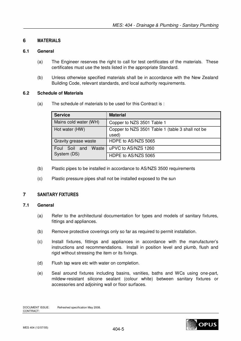
6 MATERIALS
6.1 General
(a) The Engineer reserves the right to call for test certificates of the materials. These
certificates must use the tests listed in the appropriate Standard.
(b) Unless otherwise specified materials shall be in accordance with the New Zealand
Building Code, relevant standards, and local authority requirements.
6.2 Schedule of Materials
(a) The schedule of materials to be used for this Contract is :
Service Material
Mains cold water (WH) Copper to NZS 3501 Table 1
Hot water (HW) Copper to NZS 3501 Table 1 (table 3 shall not be
used)
Gravity grease waste HDPE to AS/NZS 5065
Foul Soil and Waste
System (DS)
uPVC to AS/NZS 1260
HDPE to AS/NZS 5065
(b) Plastic pipes to be installed in accordance to AS/NZS 3500 requirements
(c) Plastic pressure pipes shall not be installed exposed to the sun
7 SANITARY FIXTURES
7.1 General
(a) Refer to the architectural documentation for types and models of sanitary fixtures,
fittings and appliances.
(b) Remove protective coverings only so far as required to permit installation.
(c) Install fixtures, fittings and appliances in accordance with the manufacturer’s
instructions and recommendations. Install in position level and plumb, flush and
rigid without stressing the item or its fixings.
(d) Flush tap ware etc with water on completion.
(e) Seal around fixtures including basins, vanities, baths and WCs using one-part,
mildew-resistant silicone sealant (colour white) between sanitary fixtures or
accessories and adjoining wall or floor surfaces.

MES: 404 - Drainage & Plumbing - Sanitary Plumbing
DOCUMENT ISSUE: Refreshed specification May 2008.
CONTRACT:
MES 404 (12/07/05) 404-6
8 ACCESSORIES
Contractor is to refer to Architect specification and documents for sanitary fixtures details
and models
8.1 Valves
(a) The isolating valve at the cold-water branch connection to the site mains shall be a
proprietary gunmetal gate valve, installed in a surface (‘toby’) box (if on buried
piping).
(b) General isolating valves in the water supply systems shall be high-pressure ball
valves with chromed DZR brass body and ball or bronze gates valves. Valve
handles shall not be steel.
(c) Isolating valves are to be installed in readily-accessible positions in the locations
indicated on the drawings. Ball valves are generally to be used in preference to
gate valves for local fixture or branch isolation.
(d) Drain points: provide gunmetal gate valves, complete with hose union where
indicated.
(e) Tempering valves shall comply with NZS 4617.
8.2 Filters/ Strainers
Contractor to install line-sized strainers as shown on drawings. Strainers are to have
bronze bodies and removable stainless steel screens with approximately 400 micron
openings.
8.3 Sink and Basin Traps
Traps, except where shown otherwise, shall be polypropylene two piece in pattern and size
to suit the waste outlet.
9 HOT WATER CYLINDERS
(a) Storage type as scheduled on drawings, complete with electric elements and all
valves, controls and thermostatic and pressure safety devices to suit the HWC and
the installation; valves shall be RMC, APEX or equal approved by the cylinder
manufacturer.
(b) Drain relief valves and drain trays to suitable discharge points.
(c) Permanently label the local electrical isolator for each controlled hot water cylinder
with the switchboard location, circuit number and the words ‘remotely controlled,
may become live without warning’.
MES: 404 - Drainage & Plumbing - Sanitary Plumbing
DOCUMENT ISSUE: Refreshed specification May 2008.
CONTRACT:
MES 404 (12/07/05) 404-7
(d) Push through type with electric elements as scheduled on drawings.
10 BOILING WATER DISPENSERS
(a) Refer to the architectural documentation for type and install in accordance with
manufacturer’s instructions and recommendations.
(b) Allow to run 15WH cold water supply to the drinks dispenser/boiling unit.
(c) Install Ball-a-flex valve at connection to allow fitting isolation.
11 INSTALLATION
11.1 General
(a) Refer also to the Architectural documentation for specific installation requirements.
(b) Install all valves and taps in the positions indicated or as required to make the
system operational.
(c) Install all materials, accessories and other specified equipment and connect to the
appropriate piped service.
11.2 Valve Access
The plumbing contractor shall be responsible for ensuring that access is provided for easy
maintenance access to concealed isolating and tempering valves and the likes that are to
be installed in the ceiling space or in wall cavities.
The plumber shall consult with and communicate to the builder that access panels be
provided and locations of these.
11.3 Seismic Restraints
(a) Support storage tanks, hot water cylinders, associated pipework, etc, where
required, against seismic movement, in accordance with NZS 4219.
(b) For hot water cylinders use proprietary galvanised steel strapping and appropriate
anchors.
11.4 Labelling
(a) Label all isolating valves, including those within ducts, ceilings and plant areas.
Identify areas served by the valves. Labels shall be engraved rigid laminated plastic
with 5 mm high white lettering on a black background. Edges of labels shall be
bevelled.
MES: 404 - Drainage & Plumbing - Sanitary Plumbing
DOCUMENT ISSUE: Refreshed specification May 2008.
CONTRACT:
MES 404 (12/07/05) 404-8
11.5 Electrical Earthing
(a) Provide all lugs and clips as necessary and as required by the electrical services.
11.6 Pipe Joints And Fittings
(a) Pipe joints unless otherwise specified, shall comply with the NZ Building Code and
good trade practice.
(b) Mechanical joints shall only be used in permanently concealed spaces where
approved.
11.7 Polypropylene (PP) and polyethylene (PE) water supply piping
(a) Pipe-to-pipe joints shall be proprietary fusion-welded type, made strictly in
accordance with the piping system manufacturer’s instructions.
(b) Pipe-to-mechanical (e.g. threaded) connections shall be proprietary fittings from the
piping system manufacturer.
(c) Connections to existing water supply mains shall be made using suitable proprietary
Gibault flange-adaptor mechanical couplings, Humes, Viking Johnson or equal.
(d) Couplings and other similar components on buried water mains shall be protected
against corrosion with proprietary petrolatum-based system, DensoTape or equal,
applied in accordance with the manufacturer’s instructions and recommendations
11.8 Copper To Copper Joints
(a) Joints connecting copper pipe, up to and including 50 mm diameter, to apparatus
shall be brass compression fittings to permit ready disconnection.
(b) Flange connections shall be used for joints to valves and equipment on copper pipe
over 50 mm diameter.
(c) Flanges shall be brass, gunmetal or bronze, machined and brazed to the tube.
Bolts shall be non-ferrous and jointing shall comply with BS 6956. Alternatively, use
pre-formed copper stub-flanges and loose backing-flanges; Kembla ‘cop-a-mate’ or
equal, installed in accordance with the manufacturer’s instructions.
(d) Compression fittings of the manipulative (Crox) type are not permitted on hot water
pipes above 25 mm diameter.
(e) Tees and branches for half hard pipe shall be capillary or socketed type. Braze
joints with an approved silver-bearing low melting-point brazing alloy complying with
BS 1845 Type CP1 or CP2.
(f) Solder ring capillary fittings may be used.

MES: 404 - Drainage & Plumbing - Sanitary Plumbing
DOCUMENT ISSUE: Refreshed specification May 2008.
CONTRACT:
MES 404 (12/07/05) 404-9
11.9 PVC pressure pipes and pipe fittings
(a) PVC pipes and pipe fittings shall be provided by the same manufacturer.
(b) Solvent welded fittings shall be cemented to the pipework in accordance with the
manufacturer's recommendations.
(c) Fabrication of pipe fittings shall not be permitted where stock moulded fittings are
available.
(d) Where fabrication of fittings is unavoidable, employ only a company specialising in
the fabrication of plastic materials.
(e) Site-made heat-welded connections will not be permitted.
11.10 Polypropylene Waste (Trap) Fittings
(a) Polypropylene waste (trap) fitting joints shall be purpose made double taper
compression joints.
11.11 Pipe Installation
(a) Set pipes in straight even gradients so as to avoid creating air locks.
(b) Use easy bends. Square elbows are not permitted. All tees shall be swept with the
flow.
(c) Bend copper pipes without buckling or damage or reducing the cross-sectional area.
If this can not be achieved then use fittings.
(d) Unless otherwise indicated all water connections terminating at fittings are to be
made through wingback fittings at wall junctions.
(e) Anchor pipes where necessary, allowing for expansion. Expansion compensation in
the water supply systems shall preferably be achieved using the flexibility of the
piping rather than by using expansion bellows or other proprietary expansion
compensators.
(f) Use vibration-isolation supports with profiled rubber liners to ensure there is no
direct contact between the piping and the building structure or other building
elements.
(g) Install PVC pipe work in accordance with AS 2032 or NZS 7643 as appropriate.
(h) Conceal pipe work unless otherwise directed by the Architect. Provide escutcheon
plates where pipes emerge through floors, walls and ceilings.
MES: 404 - Drainage & Plumbing - Sanitary Plumbing
DOCUMENT ISSUE: Refreshed specification May 2008.
CONTRACT:
MES 404 (12/07/05) 404-10
(i) Allow to paint piping and fittings that are inside the building and exposed to view.
Refer to MES 201 and the architectural documentation.
(j) Install necessary isolating valves on pipes to enable providing necessary and
appropriate maintenance to the fixtures and equipment and to install these valves in
locations to enable easy access. Contractor to coordinate with relevant contractors
to provide access to these valves.
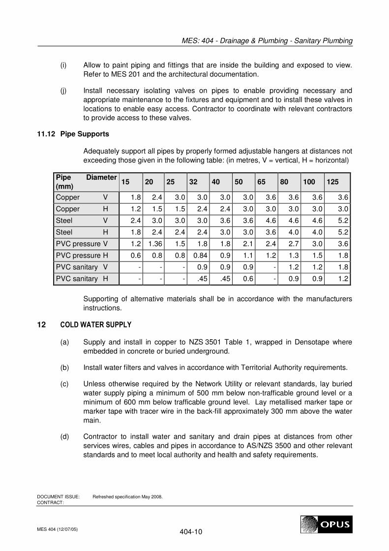
11.12 Pipe Supports
Adequately support all pipes by properly formed adjustable hangers at distances not
exceeding those given in the following table: (in metres, V = vertical, H = horizontal)
Pipe Diameter
(mm) 15 20 25 32 40 50 65 80 100 125
Copper V 1.8 2.4 3.0 3.0 3.0 3.0 3.6 3.6 3.6 3.6
Copper H 1.2 1.5 1.5 2.4 2.4 3.0 3.0 3.0 3.0 3.0
Steel V 2.4 3.0 3.0 3.0 3.6 3.6 4.6 4.6 4.6 5.2
Steel H 1.8 2.4 2.4 2.4 3.0 3.0 3.6 4.0 4.0 5.2
PVC pressure V 1.2 1.36 1.5 1.8 1.8 2.1 2.4 2.7 3.0 3.6
PVC pressure H 0.6 0.8 0.8 0.84 0.9 1.1 1.2 1.3 1.5 1.8
PVC sanitary V - - - 0.9 0.9 0.9 - 1.2 1.2 1.8
PVC sanitary H - - - .45 .45 0.6 - 0.9 0.9 1.2
Supporting of alternative materials shall be in accordance with the manufacturers
instructions.
12 COLD WATER SUPPLY
(a) Supply and install in copper to NZS 3501 Table 1, wrapped in Densotape where
embedded in concrete or buried underground.
(b) Install water filters and valves in accordance with Territorial Authority requirements.
(c) Unless otherwise required by the Network Utility or relevant standards, lay buried
water supply piping a minimum of 500 mm below non-trafficable ground level or a
minimum of 600 mm below trafficable ground level. Lay metallised marker tape or
marker tape with tracer wire in the back-fill approximately 300 mm above the water
main.
(d) Contractor to install water and sanitary and drain pipes at distances from other
services wires, cables and pipes in accordance to AS/NZS 3500 and other relevant
standards and to meet local authority and health and safety requirements.

MES: 404 - Drainage & Plumbing - Sanitary Plumbing
DOCUMENT ISSUE: Refreshed specification May 2008.
CONTRACT:
MES 404 (12/07/05) 404-11
(e) See also scope of work section.
13 HOT WATER SUPPLY
(a) Pipes shall be copper to NZS 3501 Table 1 as specified.
(b) Insulate hot and tempered hot water supply pipes in accordance with NZBC
H12/AS1 and the insulation manufacturer’s instructions & recommendations, or with
25 mm fibreglass insulation; AHI or equal; which ever is the greater.
(c) See also scope of work section and section below.
14 INSULATION
(a) Pipework Freezing Protection - Allow to apply thermal insulation to hot and cold
water pipework exposed outside the building. Forman Insulation 'Armaflex' 9.5 mm
thick is suitable and is to be additionally protected with aluminium sheathing.
(b) Where hot or cold water pipework is run within the building is must be located within
insulation in the ceiling space and walls, all so that pipework must is fully insulated.
15 DRAINAGE
Refer also to MES 405. Supply and install in PVC as specified. Shallow drainage pipes are
to be protected by concrete-encasement, against damage due to vehicles and construction
traffic.
END OF SECTIONG:\docs\mes\mes404 d & p - sanitary plumbing.doc
MES: 405 - Drainage & Plumbing - Drainage
DOCUMENT ISSUE:
CONTRACT:
MES 405 (12/07/05) 405-1
MES: 405
DRAINAGE & PLUMBING - DRAINAGE
1 SCOPE AND DESCRIPTION
(a) Building Services P&G section MES 201 applies to this section of the work.
(b) This section of the specification details specific requirements for the supply,
installation and commissioning of sanitary drainage systems.
(c) This specification covers the plumbing and drainage services as shown on the
plumbing and drainage services drawings. The demarcation between trades is
generally as shown on the drawings; typically with the plumbing & drainage services
trade terminating outside the building.
(d) The scope of works includes the provision of as built drawings as required by the
Territorial Authority and this specification.
(e) The contractor is to take particular care to ensure that the required minimum
gradients are achieved (in accordance to AS/NZS 3500.2 requirements), that piping
is adequately supported to prevent loss of gradient due to settlement, and that
piping is suitably protected against damage during and post-construction.
(f) Sewer pipework is to be laid in accordance with AS/NZS 2566.2. Sewer to be
constructed in general accordance with the NZ Building Code G13.
(a) Contractor is responsible for all temporary works in relation to the construction of the
sewer system including over pumping and wastewater management during
construction.
2 REGULATIONS
(a) The NZ Building Code and G13/AS2 for foul water drainage or G13/AS3 and
AS/NZS 3500.2, shall apply in the absence of any other standard specification or
code of practice required by the Territorial Authority or stated in this specification.
(b) Safety procedures shall comply with the requirements of the Health and Safety in
Employment Act 1992 and NZS 4452.
3 MATERIALS
(a) Materials unless otherwise specified shall be in accordance with the NZ Building
Code Approved Documents.
(b) Embedded pipes (in and under concrete slab as well as under paved areas) shall be
appropriately protected against damage due to construction, materials etc. E.g.
MES: 405 - Drainage & Plumbing - Drainage
DOCUMENT ISSUE:
CONTRACT:
MES 405 (12/07/05) 405-2
copper piping shall be wrapped in Densotape and encased in a Novacoil or similar
outer sheath.
(c) Underground PVC drain pipe and fittings shall comply with AS/NZS 1254 or AS/NZS
1260 as specified, SN rating as shown on the drawings.
(d) Bedding material including initial back-fill shall be clean sand, graded GAP7 or pea
gravel not exceeding 10mm diameter as appropriate and in accordance with
AS/NZS2566.2.
(e) Trench backfill shall be well-graded, compacted AP40 base course.
(f) Final backfill in grassed areas shall be topsoil as shown on the drawings. Final
backfill under slabs and paved areas shall be base-course backfill.
4 DRAINLAYING
(a) Excavate for drain laying in accordance with the requirements of the NZBC and/ or
the Territorial Authority, as appropriate.
(b) The contractor is to take particular care to ensure that the required minimum
gradients specified by NZBC and/or AS/NZS 3500 are achieved, that piping is
adequately supported to prevent loss of gradient due to settlement, and that piping
is suitably protected against damage during and post-construction.
(c) Piping in trafficable areas with less than 400 mm cover (top of pipe to finished
ground level) and other piping where shown on the drawings is to be concrete
encased, with due provision for movement at joints.
(d) Lay pipes on smoothly graded bedding material complying with the standard
relevant to the pipe material used and type of ground.
(e) Lay pipes to the lines and invert levels indicated or to submitted plans if design -
build. No deviation shall be permitted without prior approval.
(f) Grades steeper than 1 in 100: Lay pipes so that the invert depths at the set out
pegs will be accurate to ±3 mm. Ensure that the alignment is perfectly straight.
(g) Deviations: Immediately on completion of that portion of the work, provide the
Engineer with a scale drawing of the work as laid.
(h) Granular bedding: Lay pipes on a granular bedding having a minimum thickness of
100 mm below the pipe barrel.
(i) PVC drain pipes shall be laid in compliance with NZS 7643.
(j) Pipes in and under floor slab:
MES: 405 - Drainage & Plumbing - Drainage
DOCUMENT ISSUE:
CONTRACT:
MES 405 (12/07/05) 405-3
(i) Where pipes are embedded in the slab between reinforcing layers or
embedded in site concrete under slab, the pipe shall be protected with a pipe
sleeve, one diameter larger, along the entire embedded length. Submit
details of alternative systems for approval before installation.
(ii) Pipes in slab shall be supported to provide the required gradient and
restrained to resist flotation forces imposed during concrete placement.
(iii) Pipes under slab shall be laid in accordance with details on drawing.
5 JOINTING
(a) PVC pipes shall be jointed using seal ring mechanical joints.
(b) Pipes of other materials shall be jointed to the manufacturer's recommendations.
6 OVERFLOW RELIEF & GULLY TRAPS
Install gully traps in accordance with the NZ Building Code section G13/AS2 or Territorial
Authority requirements. Refer to ‘Covers and Gratings’ for requirements for gratings.
7 BACKFILLING
(a) No backfilling shall commence until the testing of that section of the pipe installation
is complete.
(b) Initial back-filling material shall be the same as the bedding material (refer drain
laying), and shall be to a minimum depth of 100mm above the top of the pipe.
(c) Trenches shall be backfilled and consolidated with selected backfill, free of large
stones, carefully tamped by hand around the pipe installation in 80 to 150 mm thick
layers to 300 mm above the crown of the pipe. Complete backfilling with normal fill,
compacted to the same density as the undisturbed ground in the trench sides.
(d) Trenches containing PVC pipe installations shall be backfilled and consolidated in
accordance with NZS 7643.
(e) Excepting where concrete-encased as specified, PVC pipes traversing under
roadways, drives and hard standing areas shall be protected with a 100 mm thick
concrete slab extending across the full width of the trench situated on hard fill
100mm above the top of the PVC pipe, in accordance with NZS 7643.
(f) The remainder of the trench shall be backfilled and consolidated in accordance with
NZS 7643.
(g) Reinstate the ground surface to match the original and surrounding area, unless
instructed otherwise by the Architect.

MES: 405 - Drainage & Plumbing - Drainage
DOCUMENT ISSUE:
CONTRACT:
MES 405 (12/07/05) 405-4
END OF SECTIONC:\WINDOWS\spec\mes405 d & p - drainage.doc

MES: 424 - Drainage & Plumbing - Testing & Commissioning
DOCUMENT ISSUE:
CONTRACT:
MES 424 (12/07/05) 424-1
MES: 424
DRAINAGE & PLUMBING - TESTING & COMMISSIONING
1 GENERAL
(a) Building Services P&G section specification MES201 applies to this section of the
work.
(b) The Contractor is responsible for the commissioning and shall provide all labour,
tools, and instruments as required for the full and proper testing and commissioning
of the services included within the contract works.
(c) The Engineer and/or the Architect may witness sufficient of the testing and
commissioning to demonstrate that the installed systems have been appropriately
tested and properly commissioned.
(d) The scope of the commissioning shall be to prove:
(i) Compliance with all statutory and design requirements.
(ii) Safe and proper working of the installation in all respects.
(e) The Contractor shall prepare programmes for the commissioning for approval by the
Engineer.
(f) The Contractor shall give notice of tests to the Engineer in advance by a period of
time mutually agreed early in the contract period.
2 COMMISSIONING PROCEDURES
2.1 General
(a) Testing shall be undertaken before concealing the piping, and prior to the final
connection of fixtures, fittings and appliances.
(b) In the event that any test is failed, the contractor is to repair any defects found, and
the affected system shall be re-tested.
(c) Commissioning procedures shall generally comprise visual inspection at all
installation stages, testing of all systems (staged where required), followed by
setting the installation to work, checking operation and certification.
(d) Proprietary systems shall be commissioned in accordance with the manufacturers
recommendations.
MES: 424 - Drainage & Plumbing - Testing & Commissioning
DOCUMENT ISSUE:
CONTRACT:
MES 424 (12/07/05) 424-2
2.2 Drainage Systems
(a) Drains must be tested for correct installation (laying and jointing), continuity of fall
and concentricity, before backfilling. Check continuity of fall and concentricity again
after back-filling.
(b) Use the test procedures specified in NZS 7643, and any additional tests required
that has been adopted by the Territorial Authority. Where relevant, the requirements
of NZS 7643 shall be complied with.
(c) Flood test drainage piping as per plumbing systems.
2.3 Plumbing Systems
(a) Check for leaks at fixtures, fittings and appliances.
(b) Pressure-test all water supply pipe work for a minimum of sixty minutes at not less
than 1.5 times the working pressure to the approval of the Engineer.
(c) Sanitary plumbing systems shall be flood-tested, using test-bungs to isolate sections
of plumbing piping, filling the piping to overflow level and checking for leaks.
Following successful flood-testing, drain and reconnect the piping as required, and
check for adequate drainage.
(d) Smoke-test all relief vent piping and check for leaks.
2.4 Fixtures, Fittings and Appliances
(a) Check the operation of all fixtures, fittings and appliances installed under this
contract. Adjust set-points as necessary to give proper operation.
(b) Test and commission appliances including the hot water systems in accordance with
the manufacturer’s instructions and recommendations.
(c) Adjust hot water system set-points to the specified supply temperatures.
(d) Read any water or gas meters installed under this contract. Record the readings
including the units of measurement and the date, in the Operation & Maintenance
Manual records.
END OF SECTIONC:\WINDOWS\spec\mes424 d & p - testing & commissioning.doc

MES: 425 - Drainage & Plumbing - Maintenance
DOCUMENT ISSUE:
CONTRACT:
MES 425 (12/07/05) 425-1
MES: 425
DRAINAGE & PLUMBING - MAINTENANCE
1 GENERAL
(a) Building Services P&G specification section MES:201 applies to this section of the
work.
(b) Maintain this installation for the period of twelve months after completion of the
contract
(c) Instruct nominated personnel in the correct operation and maintenance of the
systems.
(d) During the maintenance period make any additional adjustments as found
necessary under full occupancy conditions.
(e) Provide fault correction service.
(f) The contractor is to provide 24hr on call maintenance availability and be capable of
providing this level of response for all works and materials associated with this
trade.
(g) Permanent maintenance staff for the building will carry out the routine maintenance
checks listed below. Train the permanent maintenance staff in the correct
operation, adjustment and maintenance of the systems and supervise them for the
first year of operation.
(h) Remedy any faults located.
(i) Record all checks in the maintenance manual.
(j) Carry out all maintenance recommended by the manufacturers of equipment and
appliances installed under the contract.
2 MAINTENANCE CHECK LISTS
2.1 Three monthly
(a) Water filters:
(i) Check for leaks.
(ii) Review gas fired hot water system.
(iii) Rinse filters.
MES: 425 - Drainage & Plumbing - Maintenance
DOCUMENT ISSUE:
CONTRACT:
MES 425 (12/07/05) 425-2
(iv) Replace filter sleeve if damaged or unable to be cleaned satisfactorily.
2.2 Annually
(a) Clean strainers in pipework.
(b) Check water supply temperatures from water heaters and/ or tempering valves and
adjust where necessary.
(c) Check pipe work for leaks.
(d) Check operation of tapware including for signs of leakage past washer/ cartridge.
Correct any faults found.
END OF SECTIONC:\WINDOWS\spec\mes425 d & p - maintenance & plumbing.doc


