60
Motors | Automation | Energy | Transmission & Distribution | Coatings DWB Molded Case Circuit Breakers DWB

Motors | Automation | Energy | Transmission & Distribution | Coatings
DWB
Molded Case Circuit Breakers DWB

www.weg.net
Molded Case Circuit Breakers2

Summary
Presentation 04
Accessories 13
Automatic Changeover Coding - CTM 12
Short Circuit Limitation Characteristic Curves 40
General Characteristics 06
Internal Accessories 20
Protections and Settings 08
Thermal Dissipation 33
Deratings 32
External Accessories 22
Dimensions 41
Reference Code 11
Motor Operator 12
Characteristic Curves - I x t 34
Installation 29
Circuit Breaker List - Reference and Code 54
Molded Case Circuit Breakers DWB
www.weg.net
Molded Case Circuit Breakers4
The Right Circuit Breaker for Your ApplicationThe new version of DWB circuit breakers is available with three kinds of protection, that is, circuit breakers with Thermomagnetic protection, Magnetic protection or circuit breakers with Electronic LSI protection specific for each load type. For distribution circuits in general up to 800 A, the circuit breakers with Thermomagnetic element provide enough overload and short circuit protection for both AC and DC applications, allowing the economic and safe assembly of distribution systems. For distribution circuits from 500 A to 1600 A, circuit breakers with Electronic LSI protection provide optimization of the protection circuits and higher operation accuracy by means of the following protections:
In applications that require the operation and protection of motor circuits, DWB circuit breakers to 800 A have magnetic protection relays especially set for this kind of load, ensuring their correct operation in case of short-circuit currents. The circuit breakers with magnetic protection for motor circuits must be combined with other operation and protection devices, such as overload relays (thermal or electronic).For the operation and protection of generators WEG DWB circuit breakers are also manufactured with protection relays especially set for that kind of load.
Suitable for industrial, commercial and building applications, the new version of the DWB line of WEG molded case circuit breakers was designed and manufactured according to IEC 60947-1 and IEC 60947-2, meeting the operation and protection needs of distribution circuits up to 1600 A.
Protecting and Disconnecting in 5 FramesThe new version of the DW line of WEG molded case circuit breakers is available from 16 A to 1600 A in only five sizes, according to the maximum rated current of each frame size:
� DWB160 - maximum rated current of 160 A � DWB250 - maximum rated current of 250 A � DWB400 - maximum rated current of 400 A
� DWB800 and DWB10001) - maximum rated current of 800 A and 1000 A respectively
� DWB16001) - maximum rated current of 1600 ANote: 1) With Electronic LSI protection.
MOLDED CASECIRCUIT BREAKERS
� Protection against overload (“L” = Long time delay trip)� Short-time delay trip for protection against short-circuit (“S” = short-time delay), allowing selective action in case of short-
circuit currents� Instantaneous short-circuit protection ("I" = Instantaneous)

www.weg.net
Molded Case Circuit Breakers 5
� Frame made of SMC (Sheet Molding Compound): in addition to high mechanical performance, it also presents high dielectric strength and withstands high temperatures
� Fixed and moving contacts made with special metal alloys to ensure safe operation and long service life
� Electrolytic copper terminals with surface treatment (silver-coated terminals) ensuring protection against corrosion and excessive heating of the connections
� Front cover made of polycarbonate (DWB circuit breakers) providing greater safety for the applications
DWB circuit breakers allow flexibility in the use of internal accessories.
Interchangeability of accessories among circuit breakers from 160 A to 1000 A.
FLEXIBILITYIn order to provide greater safety for the operator,
DW circuit breakers have double insulation between live parts (except for the terminals) and
the front parts of the equipment. The internal accessories are completely separate from the
power circuit, avoiding any risks of contact with the live parts.
DOUBLE PROTECTIONDWB molded case circuit breakers can be used in a wide range of applications with great performance under severe overload and short circuit conditions. When installed in motor circuits
combined with WEG contactors (CWB and CWM) and WEG smart relays (SRW), they comply with coordination 2 requirements as
per IEC 60947-4-1.
HIGH PERFORMANCE
WEG DW molded case circuit breakers are manufactured with Quality and high-Performance raw materials in order to ensure high efficiency for your application.
The special laser engraving system used on DWB circuit breakers ensures indelibility of the product information and characteristic along its useful life.

www.weg.net
Molded Case Circuit Breakers6
Frame DWB160 DWB250 DWB400 DWB800 DWB1000 DWB1600Standard IEC 60947-2 IEC 60947-2 IEC 60947-2 IEC 60947-2 IEC 60947-2 IEC 60947-2Number of poles 21), 3, 414) 21), 3, 414) 3, 414) 3, 414) 3, 4 3, 4
Rated operational voltage Ue V ac 6907) 6907) 6907) 6907) 6907) 4157)
V dc 500 500 500 500 - -Insulation voltage Ui V 800 800 800 800 800 690Rated impulse withstand voltage Uimp kV 8 8 8 8 8 8Utilization category - - A A A A A AReference temperature T °C 45 45 45 45 45 45Pollution degree - - 3 3 3 3 3 3Breaking capacity level
Rated ultimate short-circuit breaking capacity - Icu
Icu
kA B N L2) B N L2) N H S H S H kA N240 V~ 25 50 120 40 80 120 40 80 65 80 65 80 240 V ~ 80380 V~ 18 303) 80 18 35 80 35 65 50 65 50 65 380 V ~ 35415 V~ 16 303) 80 16 35 80 35 50 50 65 50 65 415 V ~ 35440 V~ 10 204) 80 15 30 80 35 50 42 50 42 50 440 V ~ 25500 V~ 5 8 65 5 8 65 20 25 22 25 22 25 500 V ~ 20550 V~ 4 6 25 4 7 25 10 15 12 15 12 15 550 V ~ -690 V~ 3 4 10 3 6 15 8 10 8 10 8 10 690 V ~ -
1 pole 125 V dc 35 65 - 35 65 - 35 65 50 65 - - 125 V dc -2 poles in series 250 V dc 35 65 - 35 65 - 35 65 50 65 - - 250 V dc -3 poles in series 500 V dc 25 50 - 25 50 - 25 50 35 50 - - 500 V dc -
Rated service short-circuit breaking capacity - Ics Ics
kA B N L2) B N L2) N H S H S H kA N240 V~ 25 25 80 40 40 80 40 40 40 40 40 40 240 V ~ 40
380 / 400 V~ 16 16 60 16 17 60 35 35 35 35 35 35 380 V / 400 V ~ 25415 V~ 16 16 60 16 17 60 35 35 35 35 35 35 415 V ~ 25440 V~ 10 10 60 15 15 60 25 25 35 35 35 35 440 V ~ 25500 V~ 5 5 50 5 5 50 12 12 20 20 20 20 500 V ~ 20550 V~ 4 4 20 4 4 20 10 10 10 10 10 10 550 V ~ -690 V~ 3 3 8 3 3 8 8 8 8 8 8 8 690 V ~ -
Type of protection and application8)12)
Thermomagnetic for distribution
Fixed thermal and fixed magnetic In A16, 20, 25, 32, 40, 50, 63, 70, 80,
90, 100, 110, 125,150, 16016, 20, 25,32,40,50, 63,70, 80, 90, 100,110, 125
Not applicable Not applicable Not applicable Not applicable Not applicable
Adjustable thermal and fixed magnetic In A 40, 50, 63, 80, 100, 125, 160 - 100, 125, 160, 200, 250100, 125, 160, 200
Not applicable Not applicable Not applicable Not applicable
Adjustable thermal and adjustable magnetic
In A Not applicable Not applicable 200, 250, 320, 400 320, 400, 500, 630, 800 Not applicable Not applicable
Thermomagnetic for generator
Fixed thermal and fixed magnetic In A55, 75, 85, 105, 125, 140, 160
Not applicable Not applicable Not applicable Not applicable Not applicable Not applicable
Adjustable thermal and fixed magnetic In A Not applicable105, 125, 160,
200, 250Not applicable Not applicable Not applicable Not applicable Not applicable
Adjustable thermal and adjustable magnetic
In A Not applicable Not applicable 200, 250, 320, 400 Not applicable Not applicable 500, 630, 800, 1000 Not applicable Not applicable
Magnetic for motorFixed magnetic In A Not applicable 25, 32, 40, 50, 65, 80, 95 Not applicable 80, 105, 150, 185, 200 Not applicable Not applicable Not applicable Not applicable
Adjustable magnetic In A Not applicable Not applicable Not applicable 150, 185, 250, 320 Not applicable 420, 500 Not applicable Not applicable
Electronic (LSI) for distribution and generator A Not applicable Not applicable Not applicable Not applicable 500, 630, 800, 1000 1250, 1600
Switch-disconnector - without thermal and magnetic protection In A 125, 160 250 400 630, 800 1000 1250, 1600
Mechanical lifespan - C-O cycleNumber of operations/
operations per hour8000 / 120 8000 / 120 5000 / 120 3000 / 60 3000 / 60 3000 / 60
Electrical lifespan - C-O cycle (In @ 690 V)Number of operations/
operations per hour1000 / 120 1000 / 120 1000 / 120 In≤630 A: 1000 / 120 In=800 A: 500 / 60 In=1000 A: 500 / 60 500 / 60
Degree of protectionTerminals IP10 IP10 IP10 IP10 IP10 IP10
Accessory cover IP20 IP20 IP20 IP20 IP20 IP20Maximum air relative humidity 95% 95% 95% 95% 95% 95%
Connection with cable11)13)Recommended mm² See the Connection to Terminals section See the Connection to Terminals section See the Connection to Terminals section See the Connection to Terminals section See the Connection to Terminals section See the Connection to Terminals section
Tightening torque Nm 6 255) 305) 505) 505) 505)
Connection with bar
Recommendedcross section
(width x thickness)mm x mm See the Connection to Terminals section See the Connection to Terminals section See the Connection to Terminals section See the Connection to Terminals section See the Connection to Terminals section See the Connection to Terminals section
Tightening torque Nm 6 8 20 20 20 30 (M10) / 50 (M12)
Resistance to vibration (IEC 60068-2-6)2 a 13.2 Hz: amplitude ±1 mm
13.2 a 100 Hz: constant of acceleration 0.7 g2 a 13.2 Hz: amplitude ±1 mm
13.2 a 100 Hz: constant of acceleration 0.7 g2 a 13.2 Hz: amplitude ±1 mm
13.2 a 100 Hz: constant of acceleration 0.7 g2 a 13.2 Hz: amplitude ±1 mm
13.2 a 100 Hz: constant of acceleration 0.7 g2 a 13.2 Hz: amplitude ±1 mm
13.2 a 100 Hz: constant of acceleration 0.7 g2 a 13.2 Hz: amplitude ±1 mm
13.2 a 100 Hz: constant of acceleration 0.7 gResistance to mechanical shocks (IEC 60068-2-27 - 1/2 sine) 12 g for 11ms 12 g for 11ms 12 g for 11ms 12 g for 11ms 12 g for 11ms 12 g for 11ms
Dimensions (Width x Depth x Height) mm x mm x mm2 poles: 78 x 71 x 1223 poles: 78 x 71 x 122
4 poles: 102.5 x 71 x 122
3 poles: 78 x 136 x 143
2 poles: 105 x 78 x 1623 poles: 105 x 78 x 162 4 poles: 141 x 75 x 162
3 poles: 105 x 137 x 191
3 poles: 107 x 99 x 2564 poles: 141 x 99 x 256
3 poles: 210 x 99 x 2566) 4 poles: 280 x 99 x 2566)
3 poles: 210 x 99 x 2566) 4 poles: 280 x 99 x 2566)
3 poles: 210 x 146 x 3456) 4 poles: 280 x 146 x 3456)
Net weight kg2 poles: 0.79 /
3 poles: 0.9 / 4 poles: 1.243 poles: 1.84
2 poles: 1,42 / 3 poles: 1.85 / 4 poles: 2.5
3 poles: 3.75 3 poles: 3.56 / 4 poles: 4.6 3 poles: 7.4 / 4 poles: 9.2 3 poles: 7.4 / 4 poles: 9.2 3 poles: 16.4 / 4 poles: 19.9
General Characteristics
Notes: 1) 2 poles on the 3-pole frame, only available with fixed release and breaking capacity level B. 2) Only available on 3-pole frame; not available with protection for generator. 3) For In ≤32 A: Icu = 20 kA @ 380 V / 415 V. 4) For In ≤32 A: Icu = 15 kA @ 440 V. 5) Recommended torque for the terminal lugs accessory - PC (sold separately). If lug terminal is used directly on the circuit breaker terminal, consider the
recommended torque for connection with bar. 6) Product height without terminal cover. 7) For applications above 2000 m of altitude, consider the derating indicated in the table of page 31. 8) In = rated current (fixed thermal release) or maximum setting value (adjustable thermal release).

www.weg.net
Molded Case Circuit Breakers 7
Frame DWB160 DWB250 DWB400 DWB800 DWB1000 DWB1600Standard IEC 60947-2 IEC 60947-2 IEC 60947-2 IEC 60947-2 IEC 60947-2 IEC 60947-2Number of poles 21), 3, 414) 21), 3, 414) 3, 414) 3, 414) 3, 4 3, 4
Rated operational voltage Ue V ac 6907) 6907) 6907) 6907) 6907) 4157)
V dc 500 500 500 500 - -Insulation voltage Ui V 800 800 800 800 800 690Rated impulse withstand voltage Uimp kV 8 8 8 8 8 8Utilization category - - A A A A A AReference temperature T °C 45 45 45 45 45 45Pollution degree - - 3 3 3 3 3 3Breaking capacity level
Rated ultimate short-circuit breaking capacity - Icu
Icu
kA B N L2) B N L2) N H S H S H kA N240 V~ 25 50 120 40 80 120 40 80 65 80 65 80 240 V ~ 80380 V~ 18 303) 80 18 35 80 35 65 50 65 50 65 380 V ~ 35415 V~ 16 303) 80 16 35 80 35 50 50 65 50 65 415 V ~ 35440 V~ 10 204) 80 15 30 80 35 50 42 50 42 50 440 V ~ 25500 V~ 5 8 65 5 8 65 20 25 22 25 22 25 500 V ~ 20550 V~ 4 6 25 4 7 25 10 15 12 15 12 15 550 V ~ -690 V~ 3 4 10 3 6 15 8 10 8 10 8 10 690 V ~ -
1 pole 125 V dc 35 65 - 35 65 - 35 65 50 65 - - 125 V dc -2 poles in series 250 V dc 35 65 - 35 65 - 35 65 50 65 - - 250 V dc -3 poles in series 500 V dc 25 50 - 25 50 - 25 50 35 50 - - 500 V dc -
Rated service short-circuit breaking capacity - Ics Ics
kA B N L2) B N L2) N H S H S H kA N240 V~ 25 25 80 40 40 80 40 40 40 40 40 40 240 V ~ 40
380 / 400 V~ 16 16 60 16 17 60 35 35 35 35 35 35 380 V / 400 V ~ 25415 V~ 16 16 60 16 17 60 35 35 35 35 35 35 415 V ~ 25440 V~ 10 10 60 15 15 60 25 25 35 35 35 35 440 V ~ 25500 V~ 5 5 50 5 5 50 12 12 20 20 20 20 500 V ~ 20550 V~ 4 4 20 4 4 20 10 10 10 10 10 10 550 V ~ -690 V~ 3 3 8 3 3 8 8 8 8 8 8 8 690 V ~ -
Type of protection and application8)12)
Thermomagnetic for distribution
Fixed thermal and fixed magnetic In A16, 20, 25, 32, 40, 50, 63, 70, 80,
90, 100, 110, 125,150, 16016, 20, 25,32,40,50, 63,70, 80, 90, 100,110, 125
Not applicable Not applicable Not applicable Not applicable Not applicable
Adjustable thermal and fixed magnetic In A 40, 50, 63, 80, 100, 125, 160 - 100, 125, 160, 200, 250100, 125, 160, 200
Not applicable Not applicable Not applicable Not applicable
Adjustable thermal and adjustable magnetic
In A Not applicable Not applicable 200, 250, 320, 400 320, 400, 500, 630, 800 Not applicable Not applicable
Thermomagnetic for generator
Fixed thermal and fixed magnetic In A55, 75, 85, 105, 125, 140, 160
Not applicable Not applicable Not applicable Not applicable Not applicable Not applicable
Adjustable thermal and fixed magnetic In A Not applicable105, 125, 160,
200, 250Not applicable Not applicable Not applicable Not applicable Not applicable
Adjustable thermal and adjustable magnetic
In A Not applicable Not applicable 200, 250, 320, 400 Not applicable Not applicable 500, 630, 800, 1000 Not applicable Not applicable
Magnetic for motorFixed magnetic In A Not applicable 25, 32, 40, 50, 65, 80, 95 Not applicable 80, 105, 150, 185, 200 Not applicable Not applicable Not applicable Not applicable
Adjustable magnetic In A Not applicable Not applicable Not applicable 150, 185, 250, 320 Not applicable 420, 500 Not applicable Not applicable
Electronic (LSI) for distribution and generator A Not applicable Not applicable Not applicable Not applicable 500, 630, 800, 1000 1250, 1600
Switch-disconnector - without thermal and magnetic protection In A 125, 160 250 400 630, 800 1000 1250, 1600
Mechanical lifespan - C-O cycleNumber of operations/
operations per hour8000 / 120 8000 / 120 5000 / 120 3000 / 60 3000 / 60 3000 / 60
Electrical lifespan - C-O cycle (In @ 690 V)Number of operations/
operations per hour1000 / 120 1000 / 120 1000 / 120 In≤630 A: 1000 / 120 In=800 A: 500 / 60 In=1000 A: 500 / 60 500 / 60
Degree of protectionTerminals IP10 IP10 IP10 IP10 IP10 IP10
Accessory cover IP20 IP20 IP20 IP20 IP20 IP20Maximum air relative humidity 95% 95% 95% 95% 95% 95%
Connection with cable11)13)Recommended mm² See the Connection to Terminals section See the Connection to Terminals section See the Connection to Terminals section See the Connection to Terminals section See the Connection to Terminals section See the Connection to Terminals section
Tightening torque Nm 6 255) 305) 505) 505) 505)
Connection with bar
Recommendedcross section
(width x thickness)mm x mm See the Connection to Terminals section See the Connection to Terminals section See the Connection to Terminals section See the Connection to Terminals section See the Connection to Terminals section See the Connection to Terminals section
Tightening torque Nm 6 8 20 20 20 30 (M10) / 50 (M12)
Resistance to vibration (IEC 60068-2-6)2 a 13.2 Hz: amplitude ±1 mm
13.2 a 100 Hz: constant of acceleration 0.7 g2 a 13.2 Hz: amplitude ±1 mm
13.2 a 100 Hz: constant of acceleration 0.7 g2 a 13.2 Hz: amplitude ±1 mm
13.2 a 100 Hz: constant of acceleration 0.7 g2 a 13.2 Hz: amplitude ±1 mm
13.2 a 100 Hz: constant of acceleration 0.7 g2 a 13.2 Hz: amplitude ±1 mm
13.2 a 100 Hz: constant of acceleration 0.7 g2 a 13.2 Hz: amplitude ±1 mm
13.2 a 100 Hz: constant of acceleration 0.7 gResistance to mechanical shocks (IEC 60068-2-27 - 1/2 sine) 12 g for 11ms 12 g for 11ms 12 g for 11ms 12 g for 11ms 12 g for 11ms 12 g for 11ms
Dimensions (Width x Depth x Height) mm x mm x mm2 poles: 78 x 71 x 1223 poles: 78 x 71 x 122
4 poles: 102.5 x 71 x 122
3 poles: 78 x 136 x 143
2 poles: 105 x 78 x 1623 poles: 105 x 78 x 162 4 poles: 141 x 75 x 162
3 poles: 105 x 137 x 191
3 poles: 107 x 99 x 2564 poles: 141 x 99 x 256
3 poles: 210 x 99 x 2566) 4 poles: 280 x 99 x 2566)
3 poles: 210 x 99 x 2566) 4 poles: 280 x 99 x 2566)
3 poles: 210 x 146 x 3456) 4 poles: 280 x 146 x 3456)
Net weight kg2 poles: 0.79 /
3 poles: 0.9 / 4 poles: 1.243 poles: 1.84
2 poles: 1,42 / 3 poles: 1.85 / 4 poles: 2.5
3 poles: 3.75 3 poles: 3.56 / 4 poles: 4.6 3 poles: 7.4 / 4 poles: 9.2 3 poles: 7.4 / 4 poles: 9.2 3 poles: 16.4 / 4 poles: 19.9
General Characteristics
9) Information on thermal dissipation of the circuit breakers available on page 32.10) Thermal and magnetic operation range available on the Time x Current characteristic curves.11) See the Installation section. "Connection of cables and bars to terminals", "Direct connection of cables by means of round terminal lugs" and "Direct
connection of bar to circuit breaker" tables.12) For ambient temperature different from 45 °C, consider the deratings of the "Temperature Derating" Table.13) It is recommended to use terminal lugs accessories - PC (optional accessory for the circuit breakers, except for DWB160, which is supplied with terminal
lugs) or BE straight extension bar.14) DWB160 and DWB250 circuit breakers are available in the four-pole versions with protection on the four poles and 3P+N version with protection on three
poles and disconnection on the fourth pole. DWB400 and DWB800 circuit breakers are available in the four-pole versions with protections on three poles and disconnection on the fourth pole.

www.weg.net
Molded Case Circuit Breakers8
Im
t
l
Im
t
l
Protections and Settings
Protections
Setting for Circuit Breakers (Motors)
In order to meet the different requirements of the different types of load of an electrical circuit, DWB has special versions for each type of load, as shown below.
� Circuit breakers for distribution: thermal and magnetic protection for electric circuits in general; setting of the short circuit protection from 5 to 10 times the circuit breaker rated current, with tripping curve according to the criteria of IEC 60947-2 standard.
� Circuit breakers for motors: magnetic protection only. The short circuit tripping curve is set from 7.5 to 15 times the circuit breaker rated current. Such setting allows starting the motor without premature trip of the protection system. It is necessary to add an overcurrent relay for protection against motor overload.
� Circuit breakers for generators: the protection against short circuit is set to trip up to five times the circuit breaker rated current, protecting the generator against current surges that may damage its electronics and compromise its regulation.
DWB160 and DWB250
DWB400 and DWB800
Fixed Magnetic Protection� The circuit breaker tripping curve is fixed
Adjustable Magnetic Protection� 7.5 to 15 x ln for motors
Adjustable Magnetic Protection per Phase� 7.5 to 15 x In for motors
I >x In
Im
7.5
15
11.25
In 320 A
TEST
In 500 A11.25 7.5
15
I >x In
Im11.2511.25 7.5
15
I >x In
Im7.5
15
I >x In
Im

www.weg.net
Molded Case Circuit Breakers 9
Protections and Settings
Settings for Circuit Breakers (Distribution and Generators)
Adjustable Thermal Protection� The thermal protection curve allows setting the thermal
element from 0.8 to 1 x In
Adjustable Thermal Protection� The thermal protection curve allows setting the thermal element from
0.7 to 1 x In
Adjustable Thermal Protection� 5 to 10 x In for distribution � 2 to 5 x In for generators
Adjustable Magnetic Protection per Phase1)
� 5 to 10 x In for distribution � 2 to 5 x In for generators
Im
46
8
1012
2.7
.8
.9
.951
.65
6
7
810
4
.4
.5 3
2
I
x Inx In x Ir
L S
IiIr Is
.3.4
.1
.2.3
.2
.1
.4
70% 105%
3
1.6
12
18
6 at 8xIr (s)tr ts
2I t OFF
2I t ON
at 6xIr (s)
Is
Ii
ts
tr
Ir
Ir
Im
IrIr
Curvas para Catálogo( Linha DW 2013 )
t
i
DWB160
Fixed Thermal and Fixed Magnetic � The circuit breaker tripping curve is fixed
Adjustable Thermal and Fixed Magnetic � The thermal protection curve allows setting the
thermal element from 0.8 to 1 x In
Im
46
8
1012
2.7
.8
.9
.951
.65
6
7
810
4
.4
.5 3
2
I
x Inx In x Ir
L S
IiIr Is
.3.4
.1
.2.3
.2
.1
.4
70% 105%
3
1.6
12
18
6 at 8xIr (s)tr ts
2I t OFF
2I t ON
at 6xIr (s)
Is
Ii
ts
tr
Ir
Ir
Im
IrIr
Curvas para Catálogo( Linha DW 2013 )
t
i
DWB160 and DWB250
DWB400 and DWB800
Im
t
I
Ir
0.8
0.9
1
xIn
Ir
0.8
0.9
1
x In
Ir
1
0.9
0.8
I >x In
Im
5
10
7.5
In 400 A
Im
Ir
TEST
0.7
1
0.85
x In
Ir
In 800 A6 4
8
I >x In
Im6 4
8
I >x In
Im6 4
8
I >x In
Im
36
12
18
tr
1.6
at 6 x I (s)r
S5
6
7
810
4
2
3
Is x Ir2I t ON
2I t OFF.3.4
.1
.2.3
.2
.4
.1
at 8 x I (s)rts
46
8
1012
2
Ii x In
I.7
.8
.9
.95 1
.6
.4
.5
L
Ir
70% 105%
xIn
Ir Is IIi
Im
46
8
1012
2.7
.8
.9
.951
.65
6
7
810
4
.4
.5 3
2
I
x Inx In x Ir
L S
IiIr Is
.3.4
.1
.2.3
.2
.1
.4
70% 105%
3
1.6
12
18
6 at 8xIr (s)tr ts
2I t OFF
2I t ON
at 6xIr (s)
Is
Ii
ts
tr
Ir
Ir
Im
IrIr
Curvas para Catálogo( Linha DW 2013 )
i
t
Note: 1) Valid range up to nominal current 630 A. For nominal current 800 A: 4 to 8 x In for distribution.

www.weg.net
Molded Case Circuit Breakers10
Protections and Settings
36
12
18
tr
1.6
at 6 x I (s)r
S5
6
7
810
4
2
3
Is x Ir2I t ON
2I t OFF.3.4
.1
.2.3
.2
.4
.1
at 8 x I (s)rts
46
8
1012
2
Ii x In
I.7
.8
.9
.951
.6
.4
.5
L
Ir
70% 105%
xIn
Protections
Indication LEDs
� L (Long): overload protection with reverse time-current curve and adjustable time delay� S (Short): short circuit protection with time delay, having settings of tripping current and response time, and possibility to
choose between reverse time-current curve (I²t ON) or defined time (I²t OFF)� I (Instantaneous): short circuit protection with setting of the tripping current, without setting of the response time
� The electronic protection of the circuit breaker is self-supplied. Thus, the relay will be functional for currents equivalent to 0.2 x In for three-phase circuit or 0.35 x In for one phase supplied
70% / 105%:� LED ON when 70% of In is reached� LED flashing when 105% of In is reached
� When closing the circuit breaker after a trip, one of the LEDs of L, S and I indicates which of the settings commanded the las trip, flashing ten times. After such indication, the LEDs remain OFF
Settings for Circuit Breakers (Distribution and Generators)
DWB1600-E
DWB1000
Electronic LSI Protection
Electronic LSI Protection
36
12
18
tr1.6
at 6 x I (s)r
S5
6
7
8
4
2
3
Isx Ir
Ir
2I t ON
2I t OFF.3.4
.1
.2.3
.2
.4
.1
at 8 x I (s)r
ts4
6
8
10
2 Iix In
I.7
.8
.9
.951
.6
.4
.5
L
70% 105%
xIn
1 2 3 4 5
36
12
18
tr
1.6
at 6 x I (s)r
S5
6
7
810
4
2
3
Is x Ir2I t ON
2I t OFF.3.4
.1
.2.3
.2
.4
.1
at 8 x I (s)rts
46
8
1012
2
Ii x In
I.7
.8
.9
.951
.6
.4
.5
L
Ir
70% 105%
xIn
1 2 3 4 5
Setting of the rated current and time delay of the overload protection
Setting of the current and time delay of the short-circuit protection
Setting of the instantaneous tripping current
1 3 52 4
Long Protection (L) Short Protection (S) Instantaneous Protection (I)
Is
Ii
ts
tr
Irt
i
1
3
5
2
4
Im
t
I
Ir
0.8
0.9
1
xIn
Ir
0.8
0.9
1
x In
Ir
1
0.9
0.8
I >x In
Im
5
10
7.5
In 400 A
Im
Ir
TEST
0.7
1
0.85
x In
Ir
In 800 A6 4
8
I >x In
Im6 4
8
I >x In
Im6 4
8
I >x In
Im
36
12
18
tr
1.6
at 6 x I (s)r
S5
6
7
810
4
2
3
Is x Ir2I t ON
2I t OFF.3.4
.1
.2.3
.2
.4
.1
at 8 x I (s)rts
46
8
1012
2
Ii x In
I.7
.8
.9
.95 1
.6
.4
.5
L
Ir
70% 105%
xIn
Ir Is IIi

www.weg.net
Molded Case Circuit Breakers 11
DWB Line
Reference Code
DWB160 B 25 - 3DF Reference
DWB160 DWB800
DWB250 DWB1000
DWB400
IWB160 IWB800
IWB250 IWB1000
IWB400Rated
current
16 90
20 95
25 100
32 105
40 110
50 125
55 140
63 150
65 160
70 185
75 200
80 250
85 3202)
400
500
630
800
1000
1250
1600
Breaking capacity 380 V ac Code
18 kA B
30/35 kA N
80 kA L
65 kA H
50 kA S
Numberof poles
22)
3
4
Type of protection
Type of setting Code
Distribution
Fixed thermal and magnetic DX
Adjustable thermal, fixed magnetic DF
Adjustable thermal and magnetic DA
MotorFixed magnetic MF
Adjustable magnetic MA
Generator
Fixed thermal and magnetic GX
Adjustable thermal, fixed magnetic GF
Adjustable thermal and magnetic GA
Distributiongenerator1) Electronic LSI ET
Notes: 1) Available for frame DWB1000 and DWB1600. 2) Supplied on the 3-pole frame.

www.weg.net
Molded Case Circuit Breakers12
Note: the motor operator is sold separately from the circuit breaker.
Motor Operator
DWB400 circuit breakersRef. WEG Description10835559 Motor operator 24 V dc
10835721 Motor operator 48 V dc - 60 V dc
10835719 Motor operator 110-127 V ac / 110-125 V dc
10835720 Motor operator 230 V ac / 220 V dc
DWB800 and DWB1000 circuit
Ref. WEG Description
13179383 Motor operator 24 V dc
13179384 Motor operator 48 V dc - 60 V dc
13179386 Motor operator 110-127 V ac / 110-125 V dc
13179385 Motor operator 230 V ac / 220 V dc
DWB1600 circuit
Ref. WEG Description
13178913 Motor operator 24 V dc
13178914 Motor operator 48 V dc - 60 V dc
13178916 Motor operator 110-127 V ac / 110-125 V dc
13178915 Motor operator 230 V ac / 220 V dc
Automatic Changeover Coding - CTMSmart Code
Base
-
Left circuit breaker Right circuit breaker Poles
-
Accessories
Base typeShort-circuit
capacityRated
currentTrip unit
Short-circuit capacity
Rated current
Trip unitNumber of poles
Auxiliary contact
Alarm contact
Shunt tripUndervoltage
releaseMotor
operator
Smart Code
Example:
Base-
Left circuit breaker Right circuit breaker Poles-
Accessories
CTM 400 0 250 IW H 250 DA 4P 1 1 E26 0 C25
Base type
BTIM400 4P
Icu 380/400 V ac
Rated current
Trip un.Icu
380/400 V acRated
currentTrip un.
Zero 250 AIW: switch
disconnector65 kA 250 A DA: adjustable
thermal
Auxiliary contact
Alarm contact
Shunt tripUndervoltage
releaseMotor
operator
1 NOC 1 NOC 24 V ac/dc None 48 - 60 V dc
Reference
Base
CTM Automatic changeover CTM
400 Frame 400: DWB400 / 1000: DWB800 / DWB1000 / 1600: DWB1600
-
Left circuit breaker
0 Maximum breaking capacity N: 35 kA / S: 50 kA / H: 65 kA / L: 80 kA / 0: No capacity20 Rated current 200 / 250 / 320 / 400 / 500 / 630 / 800 / 1000 / 1250 / 1600
IW Trip unit / protection
DA: Adjustable thermal and magnetic (distribution) GA: Adjustable thermal and magnetic (generator)
MA: Adjustable magnetic (motor)ET: Electronic trip unit (DWB1000/DWB1600) E: Electronic trip unit
IW: Switch disconnector
Right circuit breaker
H Maximum breaking capacity N: 35 kA / S: 50 kA / H: 65 kA / L: 80 kA / 0: No capacity250 Rated current 200 / 250 / 320 / 400 / 500 / 630 / 800 / 1000 / 1250 / 1600
DA Trip unit / protection
DA: Adjustable thermal and magnetic (distribution) GA: Adjustable thermal and magnetic (generator)
MA: Adjustable magnetic (motor)ET: Electronic trip unit (DWB1000/DWB1600)
IWB: Switch disconnector
4P Number of poles 3P: 3 poles / 4P: 4 poles-
Accessories
1 Auxiliary contact 1 / 2
1 Alarm contact 0 / 1
E26 Shunt release BD0: none / E26: 24 V ac - V dc / E27: 48 V ac - V dc
E10: 110 - 130 V ac - V dc / E15: 220 - 250 V ac - V dc
0 Undervoltage release BS0: none / C03: 24 V dc / C07: 48 V dc / C13: 125 V dc
D60: 110 - 127 V ac / D66: 220 - 240 V ac / D70: 380 - 415 V ac D74: 440 - 480 V ac
C25 Motor operatorC03: 24 V dc / C25: 48 - 60 V dc
E51: 110-127 V ac / 110-125 V dc / E46: 230 - 220 V ac

www.weg.net
Molded Case Circuit Breakers 13
Accessories
Overview - DWB160
1 - DWB160 circuit breaker2 - BS or BD - undervoltage release or shunt release 3 - BC - auxiliary contact block4 - BFR - DIN rail base5 - CT - 90° connection extension bars (CP 90° connection
extension bars protection cover included)6 - BE - straight extension bar7 - PB - phase barrier8 - PC - terminal lugs (included in the circuit breaker)
09 - MP - escutcheon10 - BLIM - mechanical interlock 11 - PLW - padlocking device12 - MRXS - panel door rotary operating handle 13 - MRXL - panel door rotary operating handle (lenght of
handle 105 mm)14 - MRX - panel door rotary operating handle15 - MR - panel door rotary operating handle (lenght of handle
45 mm)
1
4
6
8
3
7
5
2
9
10
11
1213
1514

www.weg.net
Molded Case Circuit Breakers14
09 - MP - escutcheon 10 - BLIM - mechanical interlock 11 - PLW - padlocking device12 - MRXS - panel door rotary operating handle 13 - MRXL - panel door rotary operating handle
(lenght of handle 105 mm)14 - MR - panel door rotary operating handle (lenght
of handle 80 mm)
Overview - DWB250
Accessories
1 - DWB250 circuit breaker2 - BS or BD - undervoltage release or shunt release 3 - BC - auxiliary contact block4 - BFR - DIN rail base 5 - PC - terminal lugs6 - CT - 90° connection extension bars (CP 90° connection
extension bars protection cover included)7 - BE - straight extension bar 8 - PB - phase barrier
1
4
3
2
5
8
6
7
9
10
1112
13
14

www.weg.net
Molded Case Circuit Breakers 15
Overview - DWB400
Accessories
1 - DWB400 circuit breaker2 - PC - terminal lugs3 - BE - straight extension bar 4 - PLW - padlocking device5 - AM - motor operator6 - BLIM - mechanical interlock 7 - MRI - internal rotary operating handle8 - MP - escutcheon
09 - PB - phase barrier10 - BS or BD - undervoltage release or shunt release 11 - BC - auxiliary contact block12 - CT - 90° connection extension bars (CP 90° connection
extension bars protection cover included)13 - MRXL - panel door rotary operating handle (lenght of
handle 105 mm)14 - MR - panel door rotary operating handle (lenght of handle
80 mm)
1
1110
2
3
9
12
54
87
6
13 14

www.weg.net
Molded Case Circuit Breakers16
Overview - DWB800
Accessories
08 - BLIM - mechanical interlock09 - MP - escutcheon 10 - AM - motor operator11 - MRI - internal rotary operating handle12 - MRXL - panel door rotary operating handle (lenght of
handle 158 mm)13 - MR - panel door rotary operating handle (lenght of
handle 125 mm)
1 - DWB800 circuit breaker2 - PC - terminal lugs3 - CT - 90° connection extension bars (CP 90° connection
extension bars protection cover included)4 - BS or BD - undervoltage release or shunt release 5 - BC/AL - alarm/contact block6 - BE - straight extension bar7 - PLW - padlocking device
4
7
6
1
8 9
5
3
2
1110
1213

www.weg.net
Molded Case Circuit Breakers 17
Overview - DWB1000
Accessories
08 - BLIM - mechanical interlock 09 - MP - escutcheon 10 - AM - motor operator11 - MRI - internal rotary operating handle12 - MRXL - panel door rotary operating handle (lenght of
handle 158 mm)13 - MR - panel door rotary operating handle (lenght of
handle 125 mm)
1 - DWB1000 circuit breaker2 - PC - terminal lugs3 - CT - 90° connection extension bars (CP 90° connection
extension bars protection cover included)4 - BS or BD - undervoltage release or shunt release 5 - BC/AL - alarm/contact block6 - BE - straight extension bar7 - PLW - padlocking device
1
7
6
8 9
5
3
2
4
1011
1213

www.weg.net
Molded Case Circuit Breakers18
Overview - DWB1600
Accessories
09 - MP - escutcheon 10 - AM - motor operator11 - MRI - internal rotary operating handle12 - MRXL - panel door rotary operating handle (lenght of
handle 158 mm)13 - MR - panel door rotary operating handle (lenght of
handle 125 mm)
1 - DWB1600 circuit breaker2 - PC - terminal lugs3 - CT - 90° connection extension bars4 - BS or BD - undervoltage release or shunt release 5 - BC/AL - alarm/contact block6 - BE - straight extension bar7 - PLW - padlocking device8 - BLIM - mechanical interlock Note: The DWB1600 circuit breaker does not have the CP 90° connection extension bars protection cover.
7
5
2
8 9
3
1
4
6
1110
12
13

www.weg.net
Molded Case Circuit Breakers 19
Overview
Accessories
Description Reference
DW
B160
DW
B250
DW
B400
DW
B800
DW
B100
0
DWB1
600
Auxiliary/alarm contact1)2)
BC1-NOC √ √ √ √ √ √
BC2-NOC √ √ √ √ √ √
BC3-NOC - - - - - √
AL1-NOC √ √ √ √ √ √
BC/AL2-NOC √ √ √ √ √ √
BC/AL3-NOC - - - - - √
Undervoltage release BS2)
110/127 V ac - - √ √ √ √
220/240 V ac - - √ √ √ √
380-415 V ac - - √ √ √ √
440-480 V ac - - √ √ √ √
24 V dc - - √ √ √ √
48 V dc - - √ √ √ √
125 V dc - - - √ √ √
24 V ac / V dc √ √ - - - -
48 V ac / V dc √ √ - - - -
60 V ac / V dc √ √ - - - -
110/130 V ac / V dc √ √ - - - -
220/250 V ac / V dc √ √ - - - -
Shunt trip BD2)
24 V ac / V dc √ √ √ √ √ √
48 V ac / V dc √ √ √ √ √ √
60 V ac / V dc √ √ - - - -
110/130 V ac / V dc √ √ √ √ √ √
220/250 V ac / V dc √ √ √ √ √ √
Panel door rotary operating handle
MR / MRX √ √ √ √ √ √
MRXS √ √ - - - -
MRXL √ √ √ √ √ √
Internal rotary handle MRI - - √ √ √ √
Din rail base BFR √ √ - - - -
Front mechanical interlock BLIM √ √ √ √ √ √
Padlocking device PLW √ √ √ √ √ √
90° connection extension bars CT √ √ √ √ √ √
Straight extension bars BE √ √ √ √ √ √
Terminal lugs PC √3) √ √ √ √ √
Escutcheon MP √ √ √ √ √ √
Motor operator AM - - √ √ √ √
Phase barrier PB √ √ √ - - -
90° connection extension bars protection cover
CP √ √ √ √ √ -
Notes: 1) For combination of BC + AL, always consider the BC/AL block. It is not possible to assemble individual blocks on the circuit breaker. For example: BC1 + AL1. Replace this combination by the BC/AL2 block.
2) DWB circuit breakers are supplied without accessories. The accessories must be purchased separately and assembled at the customer's. 3) Included in the product. 4) All accessories indicated can also be used on IWB switch disconnectors.

www.weg.net
Molded Case Circuit Breakers20
Internal Accessories
Maximum Combinations of Internal Accessories
Model DWB1601) DWB2501) DWB4001) DWB800 / DWB10001) DWB16002)
2P / 3P 4P 2P / 3P 4P 2P / 3P 4P 2P / 3P 4P 3P 4P
Auxiliary contacts BC3) 2 1 2 1 4 3 4 3 2 1 2 1 4 3 4 3 2 1 2 1 4 3 4 3 4 3 4 3 8 7 8 7 4 3 4 3 8 7 8 7
Alarm contact AL3) 0 1 0 1 0 1 0 1 0 1 0 1 0 1 0 1 0 1 0 1 0 1 0 1 0 1 0 1 0 1 0 1 0 1 0 1 0 1 0 1
Model DWB1601) DWB2501) DWB4001) DWB800 / DWB10001) DWB16002)
2P / 3P 4P 2P / 3P 4P 2P / 3P 4P 2P / 3P 4P 3P 4P
Shunt trip BD 1 1 0 0 1 1 0 0 1 1 0 0 1 1 0 0 1 1 0 0 1 1 0 0 1 1 0 0 1 1 0 0 1 1 0 0 1 1 0 0
Undervoltage release BS 0 0 1 1 0 0 1 1 0 0 1 1 0 0 1 1 0 0 1 1 0 0 1 1 0 0 1 1 0 0 1 1 0 0 1 1 0 0 1 1
Notes: 1) Sold separately only. It is not sold assembled on the circuit breaker. 2) Sold assembled on the circuit breaker only. Not sold separately. 3) For combination of BC + AL, always consider the BC/AL block. It is not possible to assemble individual blocks on the circuit breaker.
BC1 + AL1, replace this combination by the BC/AL2 block.
Assembly Position of the Internal Accessories
BS / BD
BC / AL
DWB800 / DWB1000 DWB1600DWB400DWB250DWB160
Auxiliary and Alarm Contact BlocksBC - Auxiliary Contact: signals the open and closed position of the main contacts. Reversing type (1 NOC).AL - Alarm Contact: signals the thermal or magnetic release of the circuit breaker. Reversing type (1 NOC).BC/AL - Auxiliary + Alarm Contact Set: performs the 2 functions above in different contacts in a single set.
DW
B160
Ref.
WEG
3)
DW
B250
Ref.
WEG
3)
DW
B400
Ref.
WEG
3)
DW
B800
Ref.
WEG
3)
DWB1
000
Ref.
WEG
3)
DWB1
600
Ref.
WEG
3) Quantity of contacts
Auxiliary Alarm
Configuration of the contact/alarm block1)4)
BC1 10848664 10046832 1 NOC -BC2 11026395 10046833 2 NOC -BC3 - 10046834 3 NOC -AL1 11026397 10186511 - 1 NOC
BC/AL2 11026396 11648561 1 NOC 1 NOCBC/AL3 - 11648787 2 NOC 1 NOC
Notes: 1) For combinations of BC and AL (2 or 3 BCs and BC + AL) always consider the assembled set (BC2, BC3, BC/AL2 or BC/AL3). It is not possible to assemble individual blocks of BC and AL on the circuit breaker.
2) It must not be used to drive motors. 3) Sold separately only. It is not sold assembled on the circuit breaker. 4) For cable connection, consider maximum cross section of 1.5 mm² and torque of 0.8 Nm.
Conduction capacity of the contact blocks
Voltage Load type DWB160 / DWB250 / DWB400 / DWB800 / DWB1000 DWB1600
250 V acResistive 6 A 15 A
Inductive2) 3 A 12 A
125 V acResistive 6 A 15 A
Inductive2) 3 A 12 A
250 V dcResistive 0.3 A 0.3 A
Inductive2) 0.2 A 0.3 A
125 V dcResistive 0.4 A 0.6 A
Inductive2) 0.2 A 0.6 A
BC1BC2BC3AL1BCAL2BCAL3
BC1BC2AL1BCAL2BC1BC2
BC1BC2AL1BCAL2
BC1BC2AL1BCAL2
BC1BC2AL1BCAL2
BSBD
BSBD
BSBD
BSBDBS
BD

www.weg.net
Molded Case Circuit Breakers 21
Internal Accessories
Wiring Diagrams of the DWB Circuit Breaker
Undervoltage Release and Shunt Trip
BS - Undervoltage Release and BD - Shunt Trip
Wiring Diagrams of the DWB1600 Circuit Breaker
ON OFF TRIP
BC
AL
11
1222
1424
21
81
82
84
81
82
84
111222
1424
21
ON OFF TRIP
BC
AL
11 BlueBlack
Red
1222
1424
2111 Blue
Black
Red
1222
1424
21
BlueBlack
Red
82
84
81Blue
Black
Red
82
84
81
BS - Undervoltage release: it trips the circuit breaker when its operating voltage is below 35% of its rated value. That is, when the undervoltage release power supply is Ue ≤0.35 x Ue, the opening of the circuit breaker is ensured. When the voltage is within the range 0.35 < Ue < 0.7, trip may occur, and above 0.7 x Ue trip will not occur.
Note: to close the circuit breaker, BS must be energized.
Guaranteed trip Possible trip
0 0.35 0.7 1.1 Ue
Guaranteed trip
0 0.85 1.1 Ue
BD - Shunt Trip: when the shunt trip is energized by a voltage pulse, the circuit breaker trips. The trip is endured when the shunt trip command voltage is Ue > 0.85. That is, when its operating range is 0.85 < Ue < 1.10 of the rated voltage, the circuit breaker will trip.
Wiring Diagrams
D1
BS
D2
C1
C2
BD
DWB1
60DW
B250
Ref.
WEG
2)
Cons
umpt
ion
DWB4
00Re
f. W
EG2)
Cons
umpt
ion
DWB8
00DW
B100
0Re
f. W
EG2)
Cons
umpt
ion
DWB1
600
Ref.
WEG
2)
Cons
umpt
ion
Undervoltage release BS
Rated Voltage (Ue) Voltage code
110-127 V ac D60 - - 12687427 2,5 VA 13421493 5 VA 10046787 5 VA220-240 V ac D66 - - 12687479 5 VA 13421489 5 VA 10046727 5 VA380-415 V ac D70 - - 12687480 8 VA 13421495 5 VA 10046726 5 VA440-480 V ac D74 - - 12687481 9 VA 13421496 5 VA 10046762 5 VA
24 V dc C03 - - 12687425 1 W 13421490 5 W 10046785 5 W48 V dc C07 - - 12687426 1 W 13421491 5 W 10046786 5 W
125 V dc C13 - - - - - - - -24 V ac / V dc E26 11338330 2.5 VA - - - - - -48 V ac / V dc E27 11338318 2.0 VA - - - - - -60 V ac / V dc E28 11442836 2.5 VA - - - - - -
110-130 V ac / V dc E10 11338324 1.5 VA - - - - - -220-250 V ac / V dc E15 10853866 2.5 VA - - - - - -
Shunt trip BD1)
24 V ac / V dc E26 11338271 0.5 VA 12687485 130 VA 13421393 90 VA 10046782 90 VA48 V ac / V dc E27 11338248 0.5 VA 12687486 50 VA 13421394 90 VA 10046783 90 VA60 V ac / V dc E28 11442871 0,5 VA - - - - - -
110-130 V ac / V dc E10 11338254 0.5 VA 12687482 65 VA 13421391 90 VA 10046725 90 VA220-250 V ac / V dc E15 10850989 0.5 VA 12687483 65 VA 13421392 90 VA 10046724 90 VA
Min./max cable 0.5-1.5 mm² 20-16 AWG 0.5-1.5 mm² 20-16 AWG 0.5-1.5 mm² 20-16 AWG 0.5-1.5 mm² 20-16 AWGLength to strip the wire min./max. 4-6 mm 5-7 mm 5-7 mm 5-7 mmTightening torque of the terminal (N.m) 0.8 0.8 0.8 0.8Fixing tightening torque (N.m) 0.3 0.8 Snap fit 0.8
Notes: 1) It has a device to keep the coil de-energized after the trip pulse. 2) Sold separately only. It is not sold assembled on the circuit breaker.
Auxiliary and Alarm Contact Blocks

www.weg.net
Molded Case Circuit Breakers22
External Accessories
� When in ON position, panel door cannot be opened, unless a tool is used to bypass the panel door locking system, allowing thermometry of the panel.
� Circuit breaker and panel door padlocking in OFF position using 1 to 3 padlocks.
Panel Door Operating Handles
Panel Door Operating Handles (IP66)
Handle (IP66)
"A" Set: Handle + Shaft + Mechanism
"B" Set: Handle + Shaft
Only Mechanism
Notes: 1) Padlocks 4 up to 8 mm may be fit to the handles.2) Sold separately only. It is not sold assembled on the circuit breaker.
MRXS MRXS
MRXL MRXL
MRXL MRXL
Notes: 1) Padlocks 4 up to 8 mm may be fit to the handles.2) Sold separately only. It is not sold assembled on the circuit breaker.
Note: 1) Sold separately only. It is not sold assembled on the circuit breaker.
Coding
MRX S A DWB160 BUMRX: panel door operating
handle type 4X and IP66
S: selector type (DWB160 and DWB250)L: pistol type
A: Handle + Shaft + MechanismB: Handle + Shaft
"A" Set (handle + shaft + mechanism)DWB160: for circuit breaker DWB160 3P/4P DWB250: for circuit breaker DWB250 3P/4P DWB400: for circuit breaker DWB400 3P/4P DWB1000: for circuit breaker DWB800 and DWB1000 3P/4P DWB1600: for circuit breaker DWB1600 3P/4P
"B" Set (handle + shaft):1: selector type handle for circuit breaker DWB160 or DWB250 3P/4P2: pistol type handle for circuit breaker DWB160 or DWB250 3P/4P3: pistol type handle for circuit breaker DWB400 3P/4P4: pistol type handle for circuit breaker DWB800, DWB1000 or DWB1600 3P/4P
Handle colorBU: blueR: red and yellow
Ref. WEG Description Circuit breakerShaft (mm)
Length of handle (mm)
Handle color
13624516 MRXS-A-DWB160-R DWB160 3P/4P 460 - Red and yellow13624549 MRXS-A-DWB250-R DWB250 3P/4P 460 - Red and yellow13624551 MRXL-A-DWB160-R DWB160 3P/4P 460 105 Red and yellow13624610 MRXL-A-DWB250-R DWB250 3P/4P 460 105 Red and yellow13624612 MRXL-A-DWB400-R DWB400 3P/4P 460 105 Red and yellow13624616 MRXL-A-DWB1000-R DWB800 / DWB1000 3P/4P 460 158 Red and yellow13624628 MRXL-A-DWB1600-R DWB1600 3P/4P 460 158 Red and yellow13624517 MRXS-A-DWB160-BU DWB160 3P/4P 460 - Blue13624550 MRXS-A-DWB250-BU DWB250 3P/4P 460 - Blue13624553 MRXL-A-DWB160-BU DWB160 3P/4P 460 105 Blue13624611 MRXL-A-DWB250-BU DWB250 3P/4P 460 105 Blue13624613 MRXL-A-DWB400-BU DWB400 3P/4P 460 105 Blue13624617 MRXL-A-DWB1000-BU DWB800 / DWB1000 3P/4P 460 158 Blue13624629 MRXL-A-DWB1600-BU DWB1600 3P/4P 460 158 Blue
Ref. WEG Description Circuit breaker Shaft (mm)Length of handle
(mm)Handle color
13624630 MRXS-B-1-R DWB160 / DWB250 3P/4P 460 - Red and yellow13624633 MRXL-B-2-R DWB160 / DWB250 3P/4P 460 105 Red and yellow 13624635 MRXL-B-3-R DWB400 3P/4P 460 105 Red and yellow 13624660 MRXL-B-4-R DWB800 / DWB1000 / DWB1600 3P/4P 460 158 Red and yellow 13624632 MRXS-B-1-BU DWB160 / DWB250 3P/4P 460 - Blue13624634 MRXL-B-2-BU DWB160 / DWB250 3P/4P 460 105 Blue 13624636 MRXL-B-3-BU DWB400 3P/4P 460 105 Blue 13624661 MRXL-B-4-BU DWB800 / DWB1000 / DWB1600 3P/4P 460 158 Blue
Ref. WEG Description Circuit breaker
13624244 MRH DWB160 DWB160 3P/4P13624246 MRH DWB250 DWB250 3P/4P13624247 MRH DWB400 DWB400 3P/4P13624278 MRH DWB1000E DWB800 / DWB1000 3P/4P13624279 MRH DWB1600E DWB1600 3P/4P

www.weg.net
Molded Case Circuit Breakers 23
External Accessories
Note: MRI accessory may be used on frames 3P and 4P.
Circuit Ref. WEG
MRI DWB400 DWB400 12729396
MRI DWB800-1000 DWB800 DWB1000 13471816
MRI DWB1600 DWB1600 10046795
MRI - Rotary Operating Handle for Direct Operation of the Circuit Breaker� It allows rotary operation of the circuit
breaker � Padlocking in the OFF position with up to
three padlocks
Note: sold separately only. It is not sold assembled on the circuit breaker. Accessory may be used on frames 3P and 4P.
Ref. WEG Description Circuit breakerShaft length to use of support
13878675 MR DWB400 DWB400 > 380 mm
13878676 MR DWB800-1600DWB800/DWB1000/
DWB1600> 320 mm
Shaft Support� Recommended when the shaft
length is more than indicated in next table.
Note: BFR accessory may be used on frames 3P and 4P.
Circuit Ref. WEG
BFR DWB160 DWB160 12730039
BFR DW B250 DWB250 12139063
Mounting
BFR - DIN Rail Base� It allows fast assembly of the circuit breaker
on DIN rail 35 mm
Circuit Ref. WEG
BLIM DWB160 3P DWB160 11639815
BLIM DWB160 4P DWB160 12729994
BLIM DWB250 3P DWB250 11639817
BLIM DWB250 4P DWB250 12729995
BLIM DWB400 3P DWB400 12729996
BLIM DWB400 4P DWB400 11800073
BLIM DWB800-1600 3P DWB800 / DWB1000 / DWB1600 13471814
BLIM DWB800-1600 4P DWB800 / DWB1000 / DWB1600 13471815
BLIM DWA800-1600 3P DWB1600 10046798
BLIM DWA800-1600 4P DWB1600 11800074
Lock
BLIM - Front Mechanical Interlock� Mechanical lock between two circuit breakers,
preventing simultaneous closing (ON)� It allows the use of 1 to 3 padlocks of 4...8 mm
DW
B160
Ref.
WEG
DW
B250
Ref.
WEG
DW
B400
Ref.
WEG
DWB8
00DW
B100
0Re
f. W
EG
DWB1
600
Ref.
WEG
Reference handle type
Handle colorDegree of protection
Shaft length (mm)
MR Black IP55
130 12729389 11650006 12729392 - -
166 - - - 13471817 10186522
430 12729390 11650161 12729393 - -
465 - - - 13471868 10186523
MRX Black IP65130 12729251 - - - -
430 12729252 - - - -
MRX_E Red IP65130 12729253 - - - -
430 12729254 - - - -
MR - Panel Door Rotary Operating Handle� The operator can use the handle to open the panel door in the ON position (thermometry)� Total padlocking (circuit breaker + panel door) in the OFF position with up to three padlocks
MR
MRX_ENotes: 1) MR and MRX allow opening the panel door with the circuit breaker OFF only.
The door can be opened with the circuit breaker ON if the operator releases the handle safety lock. 2) Sold separately only. It is not sold assembled on the circuit breaker. 3) Padlocks 5...8 mm may be fit to the handles.

www.weg.net
Molded Case Circuit Breakers24
Circuit Cable / bar Ref. WEG
BE DWB160 3P DWB160
Use the same cable cross section and
dimensions as those of bars recommended
in the technical characteristics
(installation topic)
11279346
BE DWB160 4P DWB160 11780009
BE DWB250 3P DWB250 11279347
BE DWB250 4P DWB250 12714046
BE DWB400 3P DWB400 12730070
BE DWB400 4P DWB400 11780016
BE DWB800-1000 3P DWB800 / DWB1000 13471872
BE DWB800-1000 4P DWB800 / DWB1000 13471873
BE DWB1600 3P DWB1600 10046553
BE DWB1600 4P DWB1600 11780050
Circuit Ref. WEG
CP protection cover DWB160 3P DWB160 13544950
CP protection cover DWB250 3P DWB250 13544949
CP protection cover DWB400 3P DWB400 12731654
CP protection cover DWB800-1000 3P DWB800 / DWB1000 13544948
BE - Straight Extension Bars� It extends the terminal length and
allows connecting busbars and mounting cables with terminals
� 3-piece set
PC - Cable Connection Terminal � It allows direct
connection of cables to the circuit breaker
� 3-piece set
External Accessories1)
Connection
CP - 90° Connection Extension Bars Protection Cover� Accessory only used with 90°
connection extension bars to protect terminals and bars
� It protects the operators and everyone involved in the process against inadvertent contact
DWB1603) DWB250 DWB400 DWB800DWB1000 DWB1600
Round terminal lugs schematic drawing
Description PC DWB250 3P PC DWB400 3P PC DWB800-1000 3P PC DWB1600 3P
Number of cablesRound
terminal lugs for one cable
Round terminal lugs for one
cable (accessory)
Round terminal lugs for one
cable (accessory)
Round terminal lugs for two cables
(accessory)
Round terminal lugs for four
cables (accessory)
Maximum cable cross section (mm²)2) 70 120 240 240 240
Minimum cable cross section (mm²)2) 4 25 35 185 185
Tightening torque (mm) 6 25 30 40 45
Cable length to be stripped to use terminal lugs (mm) 16 25 25 28 38
Reference WEGSupplied with
the circuit breaker
11277469 12730045 13471871 10046555
Note: The codes of this table refer to the supply of the CP 90° connection extension bars protection cover only. 1 unit refers to the covering of the 3 phases. No protection cover for 4 poles is available. Accessory available for DWB circuit breakers only. The DWB1600 circuit breaker, for example, does not have the 90° connection extension bars protection cover.
Circuit Cable / bar Ref. WEG
CT DWB160 3P1) DWB160 Use the same cable cross section and dimensions as
those of bars recommended in
the technical characteristics
12730075
CT DWB250 3P1) DWB250 12288234
CT DWB400 3P1) DWB400 12730076
CT DWB800-1000 3P1) DWB800DWB1000
13471874
CT DWB1600 3P DWB1600 10046808
CT - 90° Connection Extension Bars � It allows direct connection of bars or
cables from the back side of the circuit breaker
Note: 1) CP 90° connection extension bars protection cover included.
Circuit Ref. WEG
PL DWB160 3P DWB160 11217445
PL DWB160 4P DWB160 12729993
PL DWB250 DWB250 (three poles and four poles) 11640142
PL DWB400 DWB400 (three poles and four poles) 11217482
PL DWB800-1600 DWB800 / DWB1000 / DWB1600
(three poles and four poles)13471813
PL1600 DWB1600 (three poles and four poles) 11640144
PLW - Padlocking Device� It allows padlocking the circuit breaker in the
OFF position. It complies with the requirements of Regulatory Standard - NR10
� It allows the use of 1 to 3 padlocks of 4...8 mm
Lock

www.weg.net
Molded Case Circuit Breakers 25
MP - Escutcheon for Circuit Breaker Operation on Panel Door� It provides perfect finishing between
the circuit breaker and panel door
Finishing4)
Notes: 1) The accessories are not sold assembled on the DWB circuit breakers. Sold separately only. 2) Recommended cross sections for cables with stranding class 2, insulation of PVC -70 °C. 3) On DWB160 circuit breakers, the cable connection terminal is included in the factory supply. Not sold as accessory. 4) MP accessory can be used on frames 3P and 4P.
Circuit Ref. WEG
MP DWB160 DWB160 11338525
MP DWB250 DWB250 11338526
MP DWB400 DWB400 12730041
MP DWB800-1600DWB800 DWB1000DWB1600
13471876
MP DWB1600 DWB1600 10186520
External Accessories
PB - Phase Barrier� The circuit breakers are supplied with two phase barriers. Those barriers must be installed on the line input side. For
voltages above 500 Volts, phase barriers must also be installed on the circuit breaker outputs. For such application, the phase barriers must be purchased. They are not supplied with the circuit breaker.
Note: see table with directions to use the phase barriers on page 30.
Circuit breaker Ref. WEG
PB DWB160-250 DWB160 / DWB250 12403111
PB DWB400 DWB400 12731651
Motor Operator
� It allows remote operation of the circuit breaker� Option of manual or automatic operation. Operation from the front of the motor operator� Control voltage (motor power supply) in the following levels:
110-127 V ac / 110-125 V dc, 230 V ac / 220 V dc, 48-60 V dc and 24 V dc� Motor operator with direct operation on the circuit breaker handle for DWB400 circuit breakers� Motor operator with spring pre-charge for DWB800, DWB1000 and DWB1600 circuit breakers
The motor operator is a mechanical and electrical device whose main characteristics are:
AM DWB400 AM DWB800 - DWB1000 AM DWB1600

www.weg.net
Molded Case Circuit Breakers26
The motor operator of the DWB400 circuit breaker allows choosing between Local and Remote operation on its front part. Assembly of AM400 must be done with the circuit breaker in the OFF position.For MANUAL operation, it is necessary:1. Set the slide switch to MANUAL. Insert the operating handle (located on the side bracket) into the front slot and rotate it 180°
clockwise;2. It must be rotated only 180º clockwise for safely operating the micro switch;3. Return the handle to the side bracket.
For AUTOMATIC operation, it is necessary:1. Set the slide switch to AUTO. In this position it is possible to operate the circuit breaker remotely by sending ON/OFF signals;2. Please, do not send ON/OFF signals simultaneously to the motor operator;3. If the circuit breaker is equipped with undervoltage release, please charge it before operating the motor operator.
DWB400 Motor Operator
Front slot / insertion of the operating
handle
Status indication of the Circuit Breaker ON and OFF
Slide switchElectrical connection
Operatinghandle
External Accessories
Wiring Diagram (DWB400) 1.2 Nm
2.5 mm2
S1 S2 S3
Ue ON OFF

www.weg.net
Molded Case Circuit Breakers 27
The functions of the motor operator, for DWB800, DWB1000 and DWB1600 circuit breakers, are operated on the front of the product through buttons and through the spring charging handle.The motor operator must be assembled with the spring discharged and the circuit breaker in the ON position.
DWB800 / DWB1000 / DWB1600 Motor Operator
Wiring Diagram (DWB800-DWB1000-DWB1600)
S1 S2 S4
Ue ON OFF
Handle to charge the spring and open the circuit breaker in manual operation
Spring status: Charged/discharged
Electrical connection
Status indication of thecircuit breaker: ON / OFF
Operating mode:Manual / automatic
Close in operation button: manual
External Accessories
1.5 mm²
15 AWG
1
2
Technical Data of the Motor Operator
Notes: The connections with the motor operator AM are done through the connection terminals. Maximum tightening torque of 1.2 Nm. The motor operator of the DWB800 circuit breaker is identical to the motor operator of the DWB1000, therefore, they can be used without restrictions. The motor operator is sold separately from the circuit breaker.
DWB400 ConsumptionDWB800 DWB1000
Consumption DWB1600 ConsumptionRated Voltage (Ue) Voltage code
Motor operator without spring pre-charge
110-125 V dc / 110-127 V ac 50/60 Hz E51 10835719 10 VA - - - -220 V dc / 230 V ac 50/60 Hz E46 10835720 10 VA - - - -
48-60 V dc C25 10835721 10 W - - - -24 V dc C03 10835559 10 W - - - -
Motor operator with spring pre-charge
110-125 V dc / 110-127 V ac 50/60 Hz E51 - - 13179386 20 VA 13178916 20 VA230 V ac / 220 V dc 50/60 Hz E46 - - 13179385 20 VA 13178915 20 VA
48-60 V dc C25 - - 13179384 20 W 13178914 20 W24 V dc C03 - - 13179383 20 W 13178913 20 W
Voltage range 0.85 a 1.1 Ue 0.85 a 1.1 Ue 0.85 a 1.1 Ue
ON time 500ms 80ms 90ms
OFF time 500ms 700ms 800ms
Trip time (using shunt trip) 15ms 15ms 20ms
Min./max cable 0.5-2.5 mm² 20-14 AWG 0.5-1.5 mm² 20-16 AWG 0.5-1.5 mm² 20-16 AWG
Length to strip the wire min./max. 5-7 mm 5-7 mm 5-7 mm
Tightening torque of the terminal (N.m) 1.2 Spring terminal Spring terminal
Fixing tightening torque (N.m) 1.2 2 2

www.weg.net
Molded Case Circuit Breakers28
External Accessories
CTM - Automatic ChangeoverThe CTM is a product set, according to IEC 60947-2, which works together to form an automatic changeover, ensuring a mechanical interlock with versatility. The system is composed of two DWB molded case circuit breakers, circuit breaker accessory (if necessary), two motor operators and mechanical interlock base (BTIM). Both circuit breakers must be connected in parallel.
Notes: The CTM set is supplied assembled. The 90° connection extension bars cannot be used as accessory in the CTM set. The circuit breaker accessory table presented on page 19 is valid for the two circuit breakers of the CTM simultaneously, that is, both circuit breakers (left and right side) must have the same accessories (mirrored configuration).
Characteristics:� Greater safety� Easy maintenance� Very simple assembly of the installation
Notes: 1) Both circuit breakers must have the same release. 2) Both circuit breakers must have the same contact or alarm block set. 3) Both circuit breakers must have the same frame. 4) Both motor operators must be identical.
Two terminal strips for connections: electrical connection with circuit breakers, accessories and motor operators.
Description Accessory CTM
Releases1)BS XBD X
Contact block2)
BC/AL2 XAL1 XBC1 X
AMAM DWB400 X
AM DWB800 - AM DWB1000 XAM DWB1600 X
BTIMDWB400 X
DWB800 - DWB1000 XDWB1600 X
Total closing + opening time between circuit breakers of a CTM
CTM Without trip coil With trip coil
400 1000ms 515ms
800-1000 780ms 95ms
1600 890ms 110ms
Opening and closing times of the motor operators
Motor operators DWB400 DWB800 / DWB1000 DWB1600
ON time 500ms 80ms 90ms
OFF time 500ms 700ms 800ms
Trip time (using shunt trip) 15ms 15ms 20ms
+ + +AM CODEMotor
operator
DWBCODE
DWB Circuit Breaker3 and 4 poles
DW CIRCUIT BREAKER ACCESSORY CODE
BTIMCODE
Rear base of mechanical interlock 3 and 4 poles

www.weg.net
Molded Case Circuit Breakers 29
IEC 60947-2 standard Un. DWB160 DWB250 DWB400 DWB800 DWB1000 DWB1600Recommended mounting distances (mm)
mmA: 50C: 20D: 20
A: 50C: 20D: 20
A: 70C: 30D: 30
A: 100C: 30D: 30
A: 100C: 30D: 30
A: 100C: 30D: 30
Recommended distances between circuit breakers for side by side mounting
mm B:10 B:10 0 0 0 0
Recommended distances between circuit breakers for vertical mount1) Non-insulated connection;2) Insulated cable;3) Terminal lugs.
mm 90 150 180 200 200 200
Assembly positions -
Dimensional drawing and mounting 2P and 3P
mmA: 100/121
(limiter) B: 25
A: 124/149(limiter) B: 35
A: 199 B: 35
A: 230 B: 70
A: 230 B: 70
A: 265 B: 70
Dimensional drawing and mounting 4P
mmA: 100/121
(limiter) B=B': 25
A: 121/149(limiter) B=B': 35
A: 199 B=B': 35
A: 230 B=B': 70
A: 230 B=B': 70
A: 265B: 70B'=74
Fixing screw to plate 2P 3P -B/N: M4 x 76 x 2 parts L: M4x76 x 1 part +
M4x144 x 1 part
B/N: M4 x 76 x 2 parts L: M4x76 x 1 part +
M4x144 x 1 part
M5 x 100 x 4 parts
M5 x 60 x 4 parts
M5 x 60 x 4 parts
M8 x 140 x 4 parts
Fixing screw to plate 4P - B/N: M4 x 76 x 3 parts B/N: M4 x 76 x 3 parts M5 x 100 x 6 parts M5 x 60 x 6 parts M5 x 60 x 6 parts M8 x 140 x 6 parts
Parts surpass of the fixing screw in relation to the circuit breaker mm 10 8 15 15 15 18
Tightening torque - mounting (Nm) Nm 1.5 1.5 3 3 3 6
Installation
Installation of the Circuit Breakers
90 ° 90 °90 °90 °
A
B B
B
DWB160 / DWB250 DWB400 / DWB800 / DWB1000 / DWB1600
B
A
B' B
A
B'B' B B' B
A A
B
A
B
A
DWB160 / DWB250 DWB400 / DWB800 / DWB1000 / DWB1600
B B
A A
D
12 3
A A A

www.weg.net
Molded Case Circuit Breakers30
Installation
Cable and Bar Connection to Terminals
Direct Cable Connection by Round Terminal Lugs
Direct Connection to the Circuit Breaker Bar
The connections to circuit breaker terminals must observe the following recommended limit:
DWB160 DWB250 DWB400 DWB800 DWB1000 DWB1600
Connection with cable
1 cable
Bare wire cord End terminal
Direct to the circuit breaker
terminalThrough round terminal lugs Through round terminal lugs Through round
terminal lugs
Through round terminal lugs - up
to 800 A only
Through round terminal lugs
Lug terminalThrough straight
extension bar
Direct to the circuit breaker
terminal2)
Through straight
extension bar
Direct to the circuit breaker
terminal2)
Through straight
extension bar
Through straight extension bar
Through straight extension bar
Through straight extension bar
2 cables
Bare wire cord End terminal
Not recommended Not recommended Not recommended Through round terminal lugs
Through round terminal lugs - up
to 800 A only
Through round terminal lugs
Lug terminalThrough straight
extension barThrough straight
extension barThrough straight
extension barThrough straight
extension barThrough straight
extension barThrough straight
extension bar
3 and 4 cables
Bare wire cord End terminal
Not recommended Not recommended Not recommended Not recommended Not recommendedThrough round terminal lugs
Lug terminalThrough straight
extension barThrough straight
extension barThrough straight
extension barThrough straight
extension barThrough straight
extension barThrough straight
extension bar
More than 4 cables
Bare wire cord End terminal
Not recommended Not recommended Not recommended Not recommended Not recommended Not recommended
Lug terminalThrough straight
extension barThrough straight
extension barThrough straight
extension barThrough straight
extension barThrough straight
extension barThrough straight
extension bar
Connection with barDirect to the
circuit breaker terminal
Direct to the circuit breaker terminal
Direct to the circuit breaker terminal
Direct to the circuit breaker
terminal
Direct to the circuit breaker
terminal
Direct to the circuit breaker
terminal
Notes: 1) The cross section of cables and bars must be observed, as well as the tightening torque informed in the product catalog.
2) Pay attention to the lug terminal size, comparing its dimension to the circuit breaker dimension. Some lug terminal models are bigger than the opening and depth of the circuit breaker terminal, and it is not possible to connect them directly to the circuit breaker terminal.
Examples of UseDirect connection of the lug terminal to the circuit breaker - 1 cable per terminal:
DWB160 DWB250 DWB400 DWB800 DWB1000 DWB1600
Round terminal lugs schematic drawing
Number of cablesRound terminal lugs
for one cableRound terminal lugs for one cable (accessory)
Round terminal lugs for one cable (accessory)
Round terminal lugs for two cables
(accessory)
Round terminal lugs for two cables
(accessory)
Round terminal lugs for four cables
(accessory)
Maximum cable cross section (mm²)3) 70 120 240 240 240 240
Minimum cable cross section (mm²)3) 4 25 35 185 185 185
Cable length to be stripped to use terminal lugs (mm) 16 25 25 28 28 38
Tightening torque (N.m) 6 25 30 50 50 50
Quantity DWB160 DWB250 DWB400 DWB800 DWB1000 DWB1600
Maximum width (mm) 10 20 20 50 50 50
Maximum thickness (mm) 7 6 12 10 10 20
Tightening torque (N.m) 6 8 20 20 20 30 (M10) / 50 (M12)
Note: recommended cross sections for cables with stranding class 2, insulation of PVC - 70 °C, according to the NM NBR 280 standard (IEC 60228).
DWB circuit breakers were designed to simplify installation on panels, as they can be supplied from the top or bottom, without compromising the technical characteristics of the components.

www.weg.net
Molded Case Circuit Breakers 31
Use of Phase Barrier and Terminal Cover
Installation
The connections to the circuit breaker terminals must observe the following recommended limit:
Notes: 1) 2 phase barriers are supplied on DWB160, DWB250 and DWB400 circuit breakers. When two more barriers are necessary, those parts are sold as accessory.
2) Protection cover supplied with the 90° connection extension bars DWB circuit breaker. For DWB1600, use the terminal cover included in the product. 3) Not supplied with the molded case circuit breakers. It must be produced by the user. 4) Minimum characteristics requirements of the material to be used as insulating plate: Dielectric strength ≥12 kV/mm.
Material not propagating flame. Recommended material: phenolite, polycarbonate.
5) Installation according to the figure above. 6) Insulating plate already included in circuito breaker DWB1600.
L ≥ circuit breaker widthH ≥ length of the terminal cover or phase barrier
Phase barriers orterminal covers1)
Phase barriers orterminal covers1)
Insulating plate3)4)
Insulating plate3)4)6)
L
H
E
D
C
B
A
1 2 3 4 5 6
Propriedade da WEG. Proibida reprodução sem autorização prévia./ WEG's property. Forbidden reproduction without previous authorization.
MASSA LÍQUIDA/NET WEIGHT
DATALIBERADOVERIFICADOEXECUTADO
DT LIBER/REL DT
LIBER/RELEASED
EXEC
VERIF/CHECKED
RESUMO DE MODIFICAÇÕES
11
EXECUTED VERDATERELEASED
FOL/SHEET
LOC SUMMARY OF MODIFICATIONSECM
SWD
- A3
ESCALA/SCALEMASSA BRUTA/GROSS WEIGHT
CHECKED
L
H
Ue <500 V Ue ≥500 V
Input Output Input Output
Connection with cable
Bare wire/cord end terminal
Mandatory use of phase barrier1) or terminal cover
Optional use of phase barrier1) or terminal cover
Mandatory use of phase barrier1) or terminal cover
Mandatory use of phase barrier1) or terminal cover
Lug terminalMandatory use of phase
barrier1) or terminal coverOptional use of phase barrier1)
or terminal coverMandatory use of phase
barrier1) or terminal coverMandatory use of phase barrier1)
or terminal cover
Connection with insulated barMandatory use of phase
barrier1) or terminal coverOptional use of phase barrier1)
or terminal coverMandatory use of phase
barrier1) or terminal coverMandatory use of phase barrier1)
or terminal cover
Connection with 90° connection extension bars2) Mandatory use of protection cover
Mandatory use of protection cover
Mandatory use of protection cover
Mandatory use of protection cover
Insulating plate3)4)5) Optional Optional Mandatory Mandatory

www.weg.net
Molded Case Circuit Breakers32
Altitude Derating
Deratings
Application of circuit breakers in altitude
Altitude (m) Derating for the rated current In Maximum rated operating voltage Ue (V)
2000 1 1
3000 0.98 0.88
4000 0.93 0.78
5000 0.90 0.68
Temperature Derating
10 °C 15 °C 20 °C 25 °C 30 °C 35 °C 40 °C 45 °C 50 °C 55 °C 60 °C
DWB160 1.20 1.16 1.13 1.10 1.06 1.05 1.03 1.00 0.98 0.94 0.91
DWB250 1.18 1.16 1.13 1.10 1.08 1.05 1.02 1.00 0.98 0.94 0.90
DWB400 1.18 1.16 1.13 1.10 1.08 1.05 1.02 1.00 0.98 0.94 0.90
DWB800 1.19 1.17 1.14 1.12 1.09 1.06 1.03 1.00 0.97 0.94 0.91
DWB1000 1.00 1.00 1.00 1.00 1.00 1.00 1.00 1.00 0.95 0.90 0.80
DWB1600 1.13 1.12 1.10 1.08 1.06 1.04 1.02 1.00 0.98 0.97 0.95
Notes: The recommended temperature refers to the place where the circuit breaker is installed. Apply the recommended derating to the rated current of the relevant circuit breaker.

www.weg.net
Molded Case Circuit Breakers 33
Circuit Protection
Thermal Dissipation
DWB160In (A) 16 20 25 32 40 50 63 70 80 90 100 110 125 150 160
Thermal dissipation (W/pole) 1 1 2 4 4 5 8 4 5 6 7 7 10 11 12
DWB160LIn (A) 16 20 25 32 40 50 63 70 80 90 100 110 125
Thermal dissipation (W/pole) 1 1 2 4 4 6 10 5 7 9 11 12 15
DWB250In (A) 100 125 160 200 250
Thermal dissipation (W/pole) 14 19 17 14 20
DWB250LIn (A) 100 125 160 200
Thermal dissipation (W/pole) 17 24 25 26
DWB400In (A) 200 250 320 400
Thermal dissipation (W/pole) 14 20 19 30
DWB800In (A) 320 400 500 630 800
Thermal dissipation (W/pole) 19 30 38 47 47
DWB1000In (A) 500 630 800 1000
Thermal dissipation (W/pole) 16 25 40 63
DWB1600In (A) 1250 1600
Thermal dissipation (W/pole) 51 96
DWB160In (A) 25 32 40 50 65 80 95
Thermal dissipation (W/pole) 2 4 4 5 6 7 7
DWB160LIn (A) 25 32 40 50 65 80 95
Thermal dissipation (W/pole) 2 4 4 6 8 9 9
DWB250In (A) 80 95 105 125 150 185 200
Thermal dissipation (W/pole) 2 3 3.5 5 7 10.5 12
DWB250LIn (A) 80 95 105 125 150 185 200
Thermal dissipation (W/pole) 4 5.5 7 9.5 13.5 21 24
DWB400In (A) 150 185 250 320
Thermal dissipation (W/pole) 14 14 20 19
DWB800In (A) 420 500
Thermal dissipation (W/pole) 32 38
Motor Protection
Generator Protection
DWB160In (A) 55 75 85 105 125 140 160
Thermal dissipation (W/pole) 7 5 6 7 10 11 12
DWB250In (A) 105 125 160 200 250
Thermal dissipation (W/pole) 14 19 17 14 20
DWB400In (A) 200 250 320 400
Thermal dissipation (W/pole) 14 20 19 30
DWB800In (A) 320 400 500 630 800
Thermal dissipation (W/pole) 19 30 38 47 47
Disconnectors
IWB160In (A) 125 160
Thermal dissipation (W/pole) 10 12
IWB250In (A) 250
Thermal dissipation (W/pole) 20
IWB400In (A) 400
Thermal dissipation (W/pole) 25
IWB800In (A) 630 800
Thermal dissipation (W/pole) 40 40
IWB1000In (A) 1000
Thermal dissipation (W/pole) 63

www.weg.net
Molded Case Circuit Breakers34
Characteristic Curves - I x t
1 1,3 2 3 4 5 6 7 8 10 20 30 40 500,01
0,02
0,05
0,1
0,2
0,5
1
2
5
10
20
50
100
200
500
1000
2000
5000
10000
20000
t (s)
x In
160A: 6,8 xIn 25A: 12 xIn20A: 15 xIn16A: 18,7 xln
150A: 7,3 xIn125A: 8,8 xIn
32 a 110A: 8,8 xIn
1 1,3 2 3 4 5 6 7 8 10 20 30 40 500,01
0,02
0,05
0,1
0,2
0,5
1
2
5
10
20
50
100
200
500
1000
2000
5000
10000
20000
t (s)
x In
1 1,3 2 3 4 5 6 7 8 10 20 30 40 500,01
0,02
0,05
0,1
0,2
0,5
1
2
5
10
20
50
100
200
500
1000
2000
5000
10000
20000
t (s)
x In
DWB160_D (Distribution)
160 A: 6.8 x ln
20000
10000
5000
2000
1000
500
200
100
50
20
10
5
2
1
0.5
0.2
0.1
0.05
0.02
0.011 1.3 2 3 4 5 6 7 8 10 20 30 40 50
x In
t (s)
25 A: 12 x ln20 A: 15 x ln
16 A: 18.7 x ln150 A: 7.3 x ln
125 A: 8.8 x ln32 to 110 A: 10 x ln
DWB160_G (Generator)
500
200
100
50
20
10
5
2
1
0.5
0.2
0.1
0.05
0.02
0.011 1.3
75 to 160 A: 5 x ln
55 A: 5.4 x ln
2 3 4 5 6 7 8 10 20 30 40x In
50
t (s)
DWB160_M (Motor)
20000
10000
5000
2000
1000
500
200
100
50
20
10
5
2
1
0.5
0.2
0.1
0.05
0.02
0.011.3 21 3 4 5 6 7 8 10 20 30 40
12 x ln
50x In
t (s)
20000
10000
5000
2000
1000

www.weg.net
Molded Case Circuit Breakers 35
Characteristic Curves - I x t
1 1,3 2 3 4 5 6 7 8 10 20 30 40 500,01
0,02
0,05
0,1
0,2
0,5
1
2
5
10
20
50
100
200
500
1000
2000
5000
10000
20000
t (s)
x In1 1,3 2 3 4 5 6 7 8 10 20 30 40 50
0,01
0,02
0,05
0,1
0,2
0,5
1
2
5
10
20
50
100
200
500
1000
2000
5000
10000
20000
t(s)
x In
10
20000
10000
5000
2000
1000
500
200
100
50
20
10
5
2
1
0.5
0.2
0.1
0.05
0.02
0.011 1.3 2 3 4 5 6 7 8 10 20 30 40 50
10 x ln
x In
t (s)
DWB250_D (Distribution) DWB250_G (Generator)
20000
10000
5000
2000
1000
500
200
100
50
20
10
5
2
1
0.5
0.2
0.1
0.05
0.02
0.011 1.3 2 3 4 5
5 x ln
6 7 8 10 20 30 40 50x In
t (s)
DWB250_M (Motor)
1 1,3 2 3 4 5 6 7 8 10 20 30 40 500,01
0,02
0,05
0,1
0,2
0,5
1
2
5
10
20
50
100
200
500
1000
2000
5000
10000
20000
t(s)
x In
20000
10000
5000
2000
1000
500
200
100
50
20
10
5
2
1
0.5
0.2
0.1
0.05
0.02
0.011.3 21 3 4 5 6 7 8 10 20 30 40
12 x ln
50x In
t (s)

www.weg.net
Molded Case Circuit Breakers36
Characteristic Curves - I x t
1 1,3 2 3 4 5 6 7 8 10 20 30 40 500,01
0,02
0,05
0,1
0,2
0,5
1
2
5
10
20
50
100
200
500
1000
2000
5000
10000
20000
t(s)
x In
1 1,3 2 3 4 5 6 7 8 10 20 30 40 500,01
0,02
0,05
0,1
0,2
0,5
1
2
5
10
20
50
100
200
500
1000
2000
5000
10000
20000
t(s)
x In
1 1,3 2 3 4 5 6 7 8 10 20 30 40 500,01
0,02
0,05
0,1
0,2
0,5
1
2
5
10
20
50
100
200
500
1000
2000
5000
10000
20000
t (s)
x In
DWB400_G (Generator)
Min. magn. adj.5 x In
Max. magn. adj.10 x In
20000
10000
5000
2000
1000
500
200
100
50
20
10
5
2
1
0.5
0.2
0.1
0.05
0.02
0.011 1.3 2 3 4 5 6 7 8 10 20 30 40 50
x In
t (s)
DWB400_M (Motor)
Max. magn. adj. 15 x In
Min. magn. adj. 7.5 x In
20000
10000
5000
2000
1000
500
200
100
50
20
10
5
2
1
0.5
0.2
0.1
0.05
0.02
0.011.3 21 3 4 5 6 7 8 10 20 30 40 50
x In
t (s)
DWB400_D (Distribution)
Min. magn. adj. 2.5 x In
20000
10000
5000
2000
1000
500
200
100
50
20
10
5
2
1
0.5
0.2
0.1
0.05
0.02
0.011 1.3 2 3 4 5 6 7 8 10 20 30 40 50
x In
t (s)
Max. magn. adj. 5 x In

www.weg.net
Molded Case Circuit Breakers 37
Characteristic Curves - I x t
1 1,3 2 3 4 5 6 7 8 10 20 30 40 500,01
0,02
0,05
0,1
0,2
0,5
1
2
5
10
20
50
100
200
500
1000
2000
5000
10000
20000
t(s)
x In
1 1,3 2 3 4 5 6 7 8 10 20 30 40 500,01
0,02
0,05
0,1
0,2
0,5
1
2
5
10
20
50
100
200
500
1000
2000
5000
10000
20000
t(s)
x In1 1,3 2 3 4 5 6 7 8 10 20 30 40 50
0,01
0,02
0,05
0,1
0,2
0,5
1
2
5
10
20
50
100
200
500
1000
2000
5000
10000
20000
t(s)
x In
.
DWB800 (Generator)
Max. magn. adj. 5 x In
Min. magn.adj. 2.5 x In
20000
10000
5000
2000
1000
500
200
100
50
20
10
5
2
1
0.5
0.2
0.1
0.05
0.02
0.011 1.3 2 3 4 5 6 7 8 10 20 30 40 50
x In
t (s
)
800 A: Min. magn. adj.
4 x In
Up to 630 A: Min. magn. adj.
5 x In
800 A: Max. magn. adj. 8 x In
Up to 630 A: Max. magn. adj.
10 x In
20000
10000
5000
2000
1000
500
200
100
50
20
10
5
2
1
0.5
0.2
0.1
0.05
0.02
0.011 1.3 2 3 4 5 6 7 8 10 20 30 40 50
x In
t (s)
DWB800 (Motor)
Min. magn. adj. 7.5 x In Max. magn.
adj. 15 x In
20000
10000
5000
2000
1000
500
200
100
50
20
10
5
2
1
0.5
0.2
0.1
0.05
0.02
0.011.3 21 3 4 5 6 7 8 10 20 30 40 50
x In
t (s)
DWB800 (Distribution)

www.weg.net
Molded Case Circuit Breakers38
Characteristic Curves - I x t
t [s]
.001
.5
.002
.02
.05
.005
.01
10
5
2
1
.2
.1
10
2
2
5
3
(1min)
10
2
2
410
1
(1h)
x Ir (r.m.s)
5
5
4 62 103 75 12 2081,05
Ir = 0.4...1xIn
3
6
1218
tr = 1.6...18s at 6xIr
1.6
.1
.2
.3
.4
i²t ON
i²t OFF
Is = 2...10xIr
.1
.2
.3
.4
ts = 0.1...0.4s at 8xlr
Tole
ranc
e ±1
0%
DWB1000 - Overload Protection (L and S) DWB1000 - Short Circuit Protection (I - Instantaneous)
t [s]
104
102
103
Ir = 0.4...1xIn
tr = 1.6...18s at 6xlr
ts = 0.1...0.4s at 8xlrIs = 2...10xlr
i2t OFF
i2t ON
(1min)
(1h)5
2
2
2
21
10
5
5
181263
.4
.4
.3
.3
.2
.2
.1
.1
1.65
.5
.05
.02
.01.005
1.05
.002
.001
.2.1
1 2 3 4 5 6 7 8 10 12 20
x Ir (r.m.s)
Tole
ranc
e ±
10%
Note: The DWB1000 can be used for the protection of both electric circuits and generators.
2...12xIn= Ii
Thermomagnetic protection
12 3 4 5 6 7 8 9 10 12 20 25 3015
x In (r.m.s)
t [s]
.001
.5
.002
.02
.05
.005
.01
10
5
2
1
.2
.1
10
2
2
5
3
(1min)
10
2
2
410
1
(1h)
x Ir (r.m.s)
5
5
4 62 103 75 12 2081,05
Ir = 0.4...1xIn
3
6
1218
tr = 1.6...18s at 6xIr
1.6
.1
.2
.3
.4
i²t ON
i²t OFF
Is = 2...10xIr
.1
.2
.3
.4
ts = 0.1...0.4s at 8xlr
Tole
ranc
e ±1
0%
DWB1600 - Overload Protection (L and S) DWB1600 - Short Circuit Protection (I - Instantaneous)
t [s]
104
102
103
Ir = 0.4...1xIn
tr = 1.6...18s at 6xlr
ts = 0.1...0.4s at 8xlrIs = 2...10xlr
i2t OFF
i2t ON
(1min)
(1h)5
2
2
2
21
10
5
5
181263
.4
.4
.3
.3
.2
.2
.1
.1
1.65
.5
.05
.02
.01.005
1.05
.002
.001
.2.1
1 2 3 4 5 6 7 8 10 12 20
x Ir (r.m.s)
Tole
ranc
e ±
10%
Note: The DWB1600-ET can be used for the protection of both electric circuits and generators.
2...12xIn= Ii
Instantaneousprotection
12 3 4 5 6 7 8 9 10 12 20 25 3015
x In (r.m.s)

www.weg.net
Molded Case Circuit Breakers 39
1 2 3 4 5 7 10 20 30 40 50 70 1001
2
3
4
5
7
10
20
30
40
50
70
100
200
Ip (k
Â)
Is (kA)1 2 3 4 5 7 10 20 30 40 50 70 100
1
2
3
4
5
7
10
20
30
40
50
70
100
200
N
B
Ip (k
Â)
Is (kA)
1 2 3 4 5 7 10 20 30 40 50 70 1001
2
3
4
5
7
10
20
30
40
50
70
100
200
Ip (kA
)
Is (kA)1 2 3 4 5 7 10 20 30 40 50 70 100
1
2
3
4
5
7
10
20
30
40
50
70
100
200
N
B
Ip (k
Â)
Is (kA)
380/415 V ac
DWB160 B/N
DWB250 B/N DWB250 L
200
100
70
50
40
30
20
10
7
54
3
2
11 2
L
3 4 5 7 10
Is (kA)
Ip (k
A)
20 30 40 50 70 100
200
100
70
50
40
30
20
10
7
5
4
3
2
11 2
B
N
3 4 5 7 10Is (kA)
Ip (k
A)
20 30 40 50 70 100
DWB160 L
1 2 3 4 5 7 10Is (kA)
20 30 40 50 70 100
200
100
70
5040
30
20
10
7
5
4
3
2
1
Ip (k
A)
1 2 3 4 5 7 10Is (kA)
20 30 40 50 70 100
200
100
70
50
40
30
20
10
7
5
4
3
2
1
Ip (k
A)
Characteristic Curves - I x t
B
N
L

www.weg.net
Molded Case Circuit Breakers40
380/415 V ac
Short Circuit Limiting Characteristic Curve
1 2 3 4 5 7 10 20 30 40 50 70 1001
2
3
4
5
7
10
20
30
40
50
70
100
200
Ip (k
Â)
Is (kA)
1 2 3 4 5 7 10 20 30 40 50 70 1001
2
3
4
5
7
10
20
30
40
50
70
100
200
Ip (k
Â)
Is (kA)
DWB400
DWB1000
200
100
70
50
40
30
20
10
7
N
H
54
3
2
11 2 3 4 5 77 1010
Ip (k
A)
Is (kA)2020 30 40404040 50 7070 100100
DWB1600
200
100
70
50
40
30
20
10
7
S
H
5
4
3
2
11 2 3 4 5 7 10
Ip (k
A)
Is (kA)
20 30 40 50 70 100
1 2 3 4 5 7 10 20 30 40 50 70 1001
2
3
4
5
7
10
20
30
40
50
70
100
200
N
HS
Ip (k
Â)
Is (kA)
H
DWB800
200
100
70
50
40
30
20
10
7
N
S
5
4
3
2
11 2 3 4 5 7 10
Is (kA)
Ip (k
A)
20 30 40 50 70 100
1 2 3 4 5 7 10 20 30 40 50 70 1001
2
3
4
5
7
10
20
30
40
50
70
100
200
N
HS
Ip (k
Â)
Is (kA)
H
200
100
70
50
40
30
20
10
7
N
S
5
4
3
2
11 2 3 4 5 7 10
Is (kA)
Ip (k
A)
20 30 40 50 70 100

www.weg.net
Molded Case Circuit Breakers 41
Circuit Breakers
Dimensions
250,984
250,984
122
4,81
0
102
4,01
6
170
6,69
2
45,2
1,77
8
261,
020
783,066
240,931
70,4
74
77,43,047
92,43,639
66
1,0125,6
0,4611,7
220,
883
481,
909
722,
850
451,77
105,84,17
351,38
351,38
135
5,31
2,
60 66
8,
1920
7,9
105.8
6645
135
3535
207.
9
250,98
250,98
102
4,02
45,2
1,78
77,93,07
6,
2615
9,1
1,
7444
,2
70,42,77
742,91
77,43,05
92,43,64
2,6667,7
2,8071,2
0,
14 3,5
5,
3513
6
22,4
0,88
48,5
1,91
2,
64 67
77.9
25
44.2
45.2
102
25
159.
1
DWB160 B/N / IWB160
DWB250 B/N / IWB250
DWB160 L
DWB250 L
4747 10
2
143
24
25 25
78
192
33 49 52
66
99
132
136
143
159
22
94
49
159
143
136
132
99
66
94
5249
33
22
73
191
45 234
135
124
35 35
34
68
135
137
149
2338
6511
4
168168
149
137
135
68
114
6538
23
24
11.7
25.6
22
48
7277.4
92.4
742525
78
26
45.2
102
122
170
6670.4
264
10,3
94
171,
56,
752
161,
56,
358
451,
772
431,
683
1064,165
351,378
351,378
135
5,31
5
331,289
68,32,689
74,82,945
783,071
833,268
230,
886
652,
569
116
4,56
9
0,7619,4
1074,206
35 35 19.4
68.3
74.8
78
83
107
23
65
116
45
135
161.
5
171.
5
264
43
33
106

www.weg.net
Molded Case Circuit Breakers42
Circuit Breakers
Dimensions
DWB400 / IWB400
DWB800 / IWB800
DWB1600
DWB1000 / IWB1000
10,1
3725
7,5
3,31
384
,14,
063
103,
2
12,7
5832
4,1
1,37835 3,902
99,14,327109,9
4,504114,4
0,9724,7
2,03
151
,6
5,33
713
5,6
5,070128,8
6,65
516
9
8,43
921
4,3
1,37835
1,37835
0,84
221
,4
10,1
3725
7,5
3,31
384
,14,
063
103,
2
12,7
5832
4,1
1,37835 3,902
99,14,327109,9
4,504114,4
0,9724,7
2,03
151
,6
5,33
713
5,6
5,070128,8
6,65
516
9
8,43
921
4,3
1,37835
1,37835
0,84
221
,4
10,1
3725
7,5
3,31
384
,14,
063
103,
2
12,7
5832
4,1
1,37835 3,902
99,14,327109,9
4,504114,4
0,9724,7
2,03
151
,6
5,33
713
5,6
5,070128,8
6,65
516
9
8,43
921
4,3
1,37835
1,37835
0,84
221
,4
8,19
208
12,7
232
3
3,8597,7
4,24107,7
4,43112,6
0,8922,7
2,03
51,4
4,69
119
6,59
167,
5
5,76146,4
9,17
232,
8
8,43
214
10,1
825
8,5
2,7670
2,7670
A
B
8,19
208
12,7
232
3
3,8597,7
4,24107,7
4,43112,6
0,8922,7
2,03
51,4
4,69
119
6,59
167,
5
5,76146,4
9,17
232,
8
8,43
214
10,1
825
8,5
2,7670
2,7670
A
B
8,19
208
12,7
232
3
3,8597,7
4,24107,7
4,43112,6
0,8922,7
2,03
51,4
4,69
119
6,59
167,
5
5,76146,4
9,17
232,
8
8,43
214
10,1
825
8,5
2,7670
2,7670
A
B
8,19
208
12,7
232
3
3,8597,7
4,24107,7
4,43112,6
0,8922,7
2,03
51,4
4,69
119
6,59
167,
5
5,76146,4
9,17
232,
8
8,43
214
10,1
825
8,5
2,7670
2,7670
A
B
8,19
208
12,7
232
3
3,8597,7
4,24107,7
4,43112,6
0,8922,7
2,03
51,4
4,69
119
6,59
167,
5
5,76146,4
9,17
232,
8
8,43
214
10,1
825
8,5
2,7670
2,7670
A
B
35 35 35
84.1
103.
2
257.
5
24.7
99.1
109.9
114.4
128.8
169
167.
511
951
.4323
258.
523
2.8
70
70 70
214
232.
825
8.5
323
208
11,2
4028
5
4,05
510
32,
303
59
19,1
1448
5
5,736146
5,8661496,130156
1,7243,6
7,948202
4,92
112
5
2,02
852
8,26
821
0
2,75670
2,75670
11,8
9030
2
11,4
7829
2
13,5
6334
5
C
70 70
292
C
302
345
11,2
4028
5
4,05
510
32,
303
59
19,1
1448
5
5,736146
5,8661496,130156
1,7243,6
7,948202
4,92
112
5
2,02
852
8,26
821
0
2,75670
2,75670
11,8
9030
2
11,4
7829
2
13,5
6334
5
C
43.6
52
125
210
146149156
202
11,2
4028
5
4,05
510
32,
303
59
19,1
1448
5
5,736146
5,8661496,130156
1,7243,6
7,948202
4,92
112
5
2,02
852
8,26
821
0
2,75670
2,75670
11,8
9030
2
11,4
7829
2
13,5
6334
5
C
103
59
285
485
8,19
208
12,7
232
3
3,8597,7
4,24107,7
4,43112,6
0,8922,7
2,03
51,4
4,69
119
6,59
167,
5
5,76146,4
9,17
232,
8
8,43
214
10,1
825
8,5
2,7670
2,7670
A
B
51.4
119
167.
5
25
148.4114.6110100
A
A
B
B
70
214
208
100
25
110114.6
148.4
135.
6
51.632
4.1
21.4
214.
3
0,9825
0,50
12,7
0,89
22,7
2x0,3
59
1,9750
DETALHE A ESCALA 2 : 1
0,9825 0,
4511
,50,
8621
,8
2x 0,359
1,9750
DETALHE B ESCALA 2 : 1
25
25
50
50
DETAIL A TOESCALE 2 : 1
DETAIL B TO ESCALE 2 : 1
12.7
11.5
21.8
22.7
2x Ø
9
2x Ø9
0,9825
0,50
12,7
0,89
22,7
2x0,3
59
1,9750
DETALHE A ESCALA 2 : 1
0,9825 0,
4511
,50,
8621
,8
2x 0,359
1,9750
DETALHE B ESCALA 2 : 1
DETAIL B TOESCALE 2 : 1
DETAIL A TO ESCALE 2 : 1
2x Ø
9
2x Ø9
25
25
50
50
12.7
11.5
22.7
21.8
1,96950
1,18130
1,26
032
2 x M10M12
0,59
115
0,88
622
,5
DETALHE CESCALA 2 : 1.5DETAIL C TO
ESCALE 2 : 1.5
15
3222
,5
50
30 M12
2 x M10
10,1
3725
7,5
3,31
384
,14,
063
103,
2
12,7
5832
4,1
1,37835 3,902
99,14,327109,9
4,504114,4
0,9724,7
2,03
151
,6
5,33
713
5,6
5,070128,8
6,65
516
9
4,193106,5
0,97
224
,7
1,37835
4x M5
7,83
519
9
8,43
921
4,3
1,37835
1,37835
0,84
221
,4L
J
I
H
G
F
E
D
C
B
A
1 2 3 4 5 6 7 8 9 10 11 12 13 14 15 16
mm [inches]1:1 A002/06/2016
DWB400-IWB400
Suj
eito
a a
ltera
ção
sem
avi
so p
révi
o. A
s in
form
açõe
s co
ntid
as s
ão v
alor
es d
e re
ferê
ncia
.
Los
valo
res
dem
ostra
dos
pued
en s
er c
ambi
ados
sin
avi
so p
revi
o. L
a in
form
ació
n és
de
refe
renc
ia s
olam
ente
.Th
e va
lues
sho
wn
are
subj
ect t
o ch
ange
with
out p
rior n
otic
e. T
he in
form
atio
n is
for r
efer
ence
onl
y.
24.7
106.5
8,19
208
12,7
232
3
3,8597,7
4,24107,7
4,43112,6
0,8922,7
2,03
51,4
4,69
119
6,59
167,
5
5,76146,4
8,27210
9,17
232,
8
8,43
214
10,1
825
8,5
2,7670
2,7670
A
B
230
9,06
4 x M
5
2,7670
0,9825
0,50
12,7
0,89
22,7
2x0,3
59
1,9750
DETALHE A ESCALA 2 : 1
0,9825 0,
4511
,50,
8621
,8
2x 0,359
1,9750
DETALHE B ESCALA 2 : 1
L
J
I
H
G
F
E
D
C
B
A
1 2 3 4 5 6 7 8 9 10 11 12 13 14 15 16
mm [inches]Escala - 1:1 A003/05/2016
DWB800-IWB800
Suj
eito
a a
ltera
ção
sem
avi
so p
révi
o. A
s in
form
açõe
s co
ntid
as s
ão v
alor
es d
e re
ferê
ncia
.
Los
valo
res
dem
ostra
dos
pued
en s
er c
ambi
ados
sin
avi
so p
revi
o. L
a in
form
ació
n és
de
refe
renc
ia s
olam
ente
.Th
e va
lues
sho
wn
are
subj
ect t
o ch
ange
with
out p
rior n
otic
e. T
he in
form
atio
n is
for r
efer
ence
onl
y.
8,19
208
12,7
232
3
3,8597,7
4,24107,7
4,43112,6
0,8922,7
2,03
51,4
4,69
119
6,59
167,
55,76
146,4
8,27210
9,17
232,
8
8,43
214
10,1
825
8,5
2,7670
2,7670
A
B
230
9,06
4 x M
5
2,7670
0,9825
0,50
12,7
0,89
22,7
2x0,3
59
1,9750
DETALHE A ESCALA 2 : 1
0,9825 0,
4511
,50,
8621
,8
2x 0,359
1,9750
DETALHE B ESCALA 2 : 1
L
J
I
H
G
F
E
D
C
B
A
1 2 3 4 5 6 7 8 9 10 11 12 13 14 15 16
mm [inches]Escala - 1:1 A003/05/2016
DWB800-IWB800
Suj
eito
a a
ltera
ção
sem
avi
so p
révi
o. A
s in
form
açõe
s co
ntid
as s
ão v
alor
es d
e re
ferê
ncia
.
Los
valo
res
dem
ostra
dos
pued
en s
er c
ambi
ados
sin
avi
so p
revi
o. L
a in
form
ació
n és
de
refe
renc
ia s
olam
ente
.Th
e va
lues
sho
wn
are
subj
ect t
o ch
ange
with
out p
rior n
otic
e. T
he in
form
atio
n is
for r
efer
ence
onl
y.
210
210
11,2
4028
5
4,05
510
32,
303
59
19,1
1448
5
5,736146
5,8661496,130156
1,7243,6
7,948202
4,92
112
5
2,02
852
8,26
821
0
8,228209
1,72
443
,8
2,75670
2,75670
11,8
9030
2
11,4
7829
2
13,5
6334
5
C
2,75670
4x M8
10,4
1326
4,5
1,96950
1,18130
1,26
032
2 x M10M12
0,59
115
0,88
622
,5
DETALHE CESCALA 2 : 1.5
L
J
I
H
G
F
E
D
C
B
A
1 2 3 4 5 6 7 8 9 10 11 12 13 14 15 16
mm [inches] 1:1.5 A002/06/216
DWA1600-IWA1600
Suj
eito
a a
ltera
ção
sem
avi
so p
révi
o. A
s in
form
açõe
s co
ntid
as s
ão v
alor
es d
e re
ferê
ncia
.
Los
valo
res
dem
ostra
dos
pued
en s
er c
ambi
ados
sin
avi
so p
revi
o. L
a in
form
ació
n és
de
refe
renc
ia s
olam
ente
.Th
e va
lues
sho
wn
are
subj
ect t
o ch
ange
with
out p
rior n
otic
e. T
he in
form
atio
n is
for r
efer
ence
onl
y.
209
43.8

www.weg.net
Molded Case Circuit Breakers 43
Accessories
Dimensions
BE - Straight Extension Bars
MP - Escutcheons
MP DWB160 MP DWB250 MP DWB400 MP DWB800 / DWB1000 / DWB1600
76
50
47
31
3
4,6
63
50
4776
50
31
Ø4.
663
376
56
47
37
3
4,6
63
3
47
Ø4.
6
3
76 47
Ø4.
65637
63
143
8037
96
9
4,6
120
96143
120
8037
Ø4.
6
9
143
118
104
78
120
9
4,6
Ø4.
6
9
Ø4.
6
78
118
120
104
143
9
Frame DWB800-1000 3P + BE
DWB800-1000
Frame 1600 3P + BE
DWB1600
70 70
472
64
209
372
302
442
486
8 (up to 1250 A) 16 (1600 A)
39
486
442
372
302
472
209
70 70
64
39 16 (1,600 A)8 (Until 1,250 A)
2,7670
2,7670
0,79
2013
,3433
8,80,7
920
8,27210
14,91
378,8
1,3734,7
0,3187020 70
210 37
2033
8.8
378.
8
8
Frame 160 3P + BE
DWB160 3P
Frame 250 3P + BE
DWB250 3P
Frame 400 3P + BE
DWB400 3P
286
35
199
35 35
107
55
131
110114.4
99
214.
6
286
324
257.
5
199
35 33
35356
21
3535
224
31
106
203
21
6
224
203
106
35 35
31
22
330 30
78
168
154
23
30
22
168
154
23
78
3030 3

www.weg.net
Molded Case Circuit Breakers44
Dimensions
Panel Door Operating Handle
MRXS
Frame 160 3P/4P + MRXS DWB160 Panel Door Cutout
Panel Door CutoutFrame 250 3P/4P + MRXS DWB250
MRXS - Panel Door Operating Handle
Accessories
Y
X
Y
X
Y
X
Y
X
Y
X
Y
X
X
Y
X
Y
5.5
X
X
Y
Y
2.5
4
119.9
130
180...557
190...567
62.4
62.35
Y
Y
46
46
46
Máx. 5
Máx. 5
Ø44
Ø44
Ø4
46
Ø4
X
X
E
D
C
B
A
1 2 3 4 5 6
Propriedade da WEG. Proibida reprodução sem autorização prévia./ WEG's property. Forbidden reproduction without previous authorization.
DATAEXECUTADO
EXECEXECUTED DATERELEASEDLOC SUMMARY OF MODIFICATIONSECM CHECKED
61.6
76.8
E
D
C
B
A
1 2 3 4 5 6
Propriedade da WEG. Proibida reprodução sem autorização prévia./ WEG's property. Forbidden reproduction without previous authorization.
DATAEXECUTADO
EXECEXECUTED DATERELEASEDLOC SUMMARY OF MODIFICATIONSECM CHECKED
104.9
85.8
E
D
C
B
A
1 2 3 4 5 6
Propriedade da WEG. Proibida reprodução sem autorização prévia./ WEG's property. Forbidden reproduction without previous authorization.
DATAEXECUTADO
EXECEXECUTED DATERELEASEDLOC SUMMARY OF MODIFICATIONSECM CHECKED
85.8
157.7
MRXL MRXL

www.weg.net
Molded Case Circuit Breakers 45
Dimensions
Y
X
Y
X
X
Y
X
Y
E
D
C
B
A
1 2 3 4 5 6
Propriedade da WEG. Proibida reprodução sem autorização prévia./ WEG's property. Forbidden reproduction without previous authorization.
DATAEXECUTADO
EXECEXECUTED DATERELEASEDLOC SUMMARY OF MODIFICATIONSECM CHECKED
Y
X
Y
X
Y
X
Y
X
E
D
C
B
A
1 2 3 4 5 6
Propriedade da WEG. Proibida reprodução sem autorização prévia./ WEG's property. Forbidden reproduction without previous authorization.
DATAEXECUTADO
EXECEXECUTED DATERELEASEDLOC SUMMARY OF MODIFICATIONSECM CHECKED
Y
X
Y
X
Y
X
Y
X
E
D
C
B
A
1 2 3 4 5 6
Propriedade da WEG. Proibida reprodução sem autorização prévia./ WEG's property. Forbidden reproduction without previous authorization.
DATAEXECUTADO
EXECEXECUTED DATERELEASEDLOC SUMMARY OF MODIFICATIONSECM CHECKED
Y
X
Y
X
X
Y
X
Y
1 2 3 4 5 6
Panel Door Cutout
Panel Door Cutout
Frame 250 3P/4P + MRXL DWB250
Frame 160 3P/4P + MRXL DWB160
MRXL - Panel Door Operating Handle
Accessories
Y Y
Y
X X
X
4
Ø44
Ø44
Ø5.5
Ø5.5
Y
5.5
X
2.5
180...550
190...565
119.9
130
73
73
57
57
57
57
Máx. 5
Máx. 5

www.weg.net
Molded Case Circuit Breakers46
Dimensions
Y
X
Y
X
E
D
C
B
A
1 2 3 4 5 6
Propriedade da WEG. Proibida reprodução sem autorização prévia./ WEG's property. Forbidden reproduction without previous authorization.
DATAEXECUTADO
EXECEXECUTED DATERELEASEDLOC SUMMARY OF MODIFICATIONSECM CHECKED
Y
X
Y
X
E
D
C
B
A
1 2 3 4 5 6
Propriedade da WEG. Proibida reprodução sem autorização prévia./ WEG's property. Forbidden reproduction without previous authorization.
DATAEXECUTADO
EXECEXECUTED DATERELEASEDLOC SUMMARY OF MODIFICATIONSECM CHECKED
Y
X
Y
X
Y
Y
X
E
D
C
B
A
1 2 3 4 5 6
Propriedade da WEG. Proibida reprodução sem autorização prévia./ WEG's property. Forbidden reproduction without previous authorization.
DATAEXECUTADO
EXECEXECUTED DATERELEASEDLOC SUMMARY OF MODIFICATIONSECM CHECKED
MRXL - Panel Door Operating Handle
Accessories
Frame DWB800-1000 + MRXL DWB800-1000
Frame 1600 3P/4P + MRXL DWB1600
Frame 400 3P/4P + MRXL DWB400
Y
X
Y
X
Y
Y
X
Y
X
Y
X
Y
X
Y
X
Y
Y
Y
200...617
200...573
250...621
7
83.5
5
79.3
X
X
X
178.3
158.1
205.8
73
74.1
74.14
Máx. 5
Máx. 5
Máx. 5
Ø44
Ø44
Ø44
Ø5.5
Ø5.5
Ø5.5
Y
Y
Y
7
57
75
83.5
5
X
X
X
Panel Door Cutout
Panel Door Cutout
Panel Door Cutout
57
75

www.weg.net
Molded Case Circuit Breakers 47
MR - Panel Door Operating Handle
Accessories
Frame 160 3P/4P + MRX DWB160 Panel Door Cutout
Panel Door CutoutFrame 160 3P/4P + MR DWB160
Panel Door CutoutFrame 250 3P/4P + MR DWB250
Y
Y
Y
XX
XX
Y
Y
XX
Y
Y
XX
Y
Y
XX
Y
Y
XX
Y
Y
Y
Y
X X
Y
Y
XX
X X
Y
Y
Y
XX
Y
Y
X
Y
X
Y
X
Y
X
Y
X X
Y
X X
Y
Y
XX
Y
MR DWA800
MRX DWB160
MR DWB250
MR DWA1600
MR DWB160
MRB DWB160
MR DWA400Furação da porta do Painel
Furação da porta do Painel
Furação da porta do Painel
Furação da porta do Painel
Furação da porta do Painel
Furação da porta do Painel
Furação da porta do Painel120
122
222...520
3627
2 0 5
305...580
5 46
156
256...580
5 46
129
229...520
5 46
122
222...520
5 46
180
280...550
5 46
3
5
3
5
0
8
5
3
0
4
2
46
2
81
5
3
45°
0
4
45°
2
81
45°
2
46
45°
0
8
45°
5
3
Ø22,5
24,5
3,2
5
3
Ø25... Ø
28
Ø5
48,5
48,5
5
3
45°
Ø53
Ø5
Ø 31
Ø53
Ø5
Ø 31
Ø 53Ø 5
Ø31
Ø 53Ø 5
Ø31
Ø 53Ø 5
Ø31
Ø40 Ø
4
Ø 21
Ø53
Y4
Ø31
XX
Y
Y4
0
Ø53
Ø5
45°
Y
Y
Y
XX
XX
Y
Y
XX
Y
Y
XX
Y
Y
XX
Y
Y
XX
Y
Y
Y
Y
X X
Y
Y
XX
X X
Y
Y
Y
XX
Y
Y
X
Y
X
Y
X
Y
X
Y
X X
Y
X X
Y
Y
XX
Y
MR DWA800
MRX DWB160
MR DWB250
MR DWA1600
MR DWB160
MRB DWB160
MR DWA400Furação da porta do Painel
Furação da porta do Painel
Furação da porta do Painel
Furação da porta do Painel
Furação da porta do Painel
Furação da porta do Painel
Furação da porta do Painel120
122
222...520
3627
2 0 5
305...580
5 46
156
256...580
5 46
129
229...520
5 46
122
222...520
5 46
180
280...550
5 46
3
5
3
5
0
8
5
3
0
4
2
46
2
81
5
3
45°
0
4
45°
2
81
45°
2
46
45°
0
8
45°
5
3
Ø22,5
24,5
3,2
5
3
Ø25... Ø
28
Ø5
48,5
48,5
5
3
45°
Ø53
Ø5
Ø 31
Ø53
Ø5
Ø 31
Ø 53Ø 5
Ø31
Ø 53Ø 5
Ø31
Ø 53Ø 5
Ø31
Ø40 Ø
4
Ø 21
46
X
5
229...520
129
XX 0
Y
Y4
Y
Y
Y
XX
XX
Y
Y
XX
Y
Y
XX
Y
Y
XX
Y
Y
XX
Y
Y
Y
Y
X X
Y
Y
XX
X X
Y
Y
Y
XX
Y
Y
X
Y
X
Y
X
Y
X
Y
X X
Y
X X
Y
Y
XX
Y
MR DWA800
MRX DWB160
MR DWB250
MR DWA1600
MR DWB160
MRB DWB160
MR DWA400Furação da porta do Painel
Furação da porta do Painel
Furação da porta do Painel
Furação da porta do Painel
Furação da porta do Painel
Furação da porta do Painel
Furação da porta do Painel120
122
222...520
3627
2 0 5
305...580
5 46
156
256...580
5 46
129
229...520
5 46
122
222...520
5 46
180
280...550
5 46
3
53
5
0
8
5
3
0
4
2
46
2
81
5
3
45°
0
4
45°
2
81
45°
2
46
45°
0
8
45°
5
3
Ø22,5
24,5
3,2
5
3
Ø25... Ø
28
Ø5
48,5
48,5
5
3
45°
Ø53
Ø5
Ø 31
Ø53
Ø5
Ø 31
Ø 53Ø 5
Ø31
Ø 53Ø 5
Ø31
Ø 53Ø 5
Ø31
Ø40 Ø
4
Ø 21
X
Y
Y Y
3
Ø31
Ø5
XX
Ø53
5
45°
Y
Y
Y
XX
XX
Y
Y
XX
Y
Y
XX
Y
Y
XX
Y
Y
XX
Y
Y
Y
Y
X X
Y
Y
XX
X X
Y
Y
Y
XX
Y
Y
X
Y
X
Y
X
Y
X
Y
X X
Y
X X
Y
Y
XX
Y
MR DWA800
MRX DWB160
MR DWB250
MR DWA1600
MR DWB160
MRB DWB160
MR DWA400Furação da porta do Painel
Furação da porta do Painel
Furação da porta do Painel
Furação da porta do Painel
Furação da porta do Painel
Furação da porta do Painel
Furação da porta do Painel120
122
222...520
3627
2 0 5
305...580
5 46
156
256...580
5 46
129
229...520
5 46
122
222...520
5 46
180
280...550
5 46
3
5
3
5
0
8
5
3
0
4
2
46
2
81
5
3
45°
0
4
45°
2
81
45°
2
46
45°
0
8
45°
5
3
Ø22,5
24,5
3,2
5
3
Ø25... Ø
28
Ø5
48,5
48,5
5
3
45°
Ø53
Ø5
Ø 31
Ø53
Ø5
Ø 31
Ø 53Ø 5
Ø31
Ø 53Ø 5
Ø31
Ø 53Ø 5
Ø31
Ø40 Ø
4
Ø 21
XX
5
X X
Y
Y
3 120
XX
Y
Ø22.5
3
3.2
24.5
Y
5
Y48.53
Ø25...Ø28
48.5
Y
X
5
Ø5
Y
Y
Y
XX
XX
Y
Y
XX
Y
Y
XX
Y
Y
XX
Y
Y
XX
Y
Y
Y
Y
X X
Y
Y
XX
X X
Y
Y
Y
XX
Y
Y
X
Y
X
Y
X
Y
X
Y
X X
Y
X X
Y
Y
XX
Y
MR DWA800
MRX DWB160
MR DWB250
MR DWA1600
MR DWB160
MRB DWB160
MR DWA400Furação da porta do Painel
Furação da porta do Painel
Furação da porta do Painel
Furação da porta do Painel
Furação da porta do Painel
Furação da porta do Painel
Furação da porta do Painel120
122
222...520
3627
2 0 5
305...580
5 46
156
256...580
5 46
129
229...520
5 46
122
222...520
5 46
180
280...550
5 46
3
5
3
5
0
8
5
3
0
4
2
46
2
81
5
3
45°
0
4
45°
2
81
45°
2
46
45°
0
8
45°
5
3
Ø22,5
24,5
3,2
5
3
Ø25... Ø
28
Ø5
48,5
48,5
5
3
45°
Ø53
Ø5
Ø 31
Ø53
Ø5
Ø 31
Ø 53Ø 5
Ø31
Ø 53Ø 5
Ø31
Ø 53Ø 5
Ø31
Ø40 Ø
4
Ø 21
X
5
XX
Y
3
122
222...520
465
Y
Dimensions

www.weg.net
Molded Case Circuit Breakers48
MR - Panel Door Operating Handle
Accessories
Dimensions
Frame 1600 3P/4P + MR DWB1600
Frame DWB800-1000 + MR DWB800-1000
Panel Door Cutout
Panel Door Cutout
Panel Door Cutout
Frame 400 3P/4P + MR DWB400
107
53
136
35
35 35 35
107141 (4P)
214.
6
324
257.
5
199
136
35
539924
181
589
35
Y
Y
Y
XX
XX
Y
Y
XX
Y
Y
XX
Y
Y
XX
Y
Y
XX
Y
Y
Y
Y
X X
Y
Y
XX
X X
Y
Y
Y
XX
Y
Y
X
Y
X
Y
X
Y
X
Y
X X
Y
X X
Y
Y
XX
Y
MR DWA800
MRX DWB160
MR DWB250
MR DWA1600
MR DWB160
MRB DWB160
MR DWA400Furação da porta do Painel
Furação da porta do Painel
Furação da porta do Painel
Furação da porta do Painel
Furação da porta do Painel
Furação da porta do Painel
Furação da porta do Painel120
122
222...520
3627
2 0 5
305...580
5 46
156
256...580
5 46
129
229...520
5 46
122
222...520
5 46
180
280...550
5 46
3
5
3
5
0
8
5
3
0
4
2
46
2
81
5
3
45°
0
4
45°
2
81
45°
2
46
45°
0
8
45°
5
3
Ø22,5
24,5
3,2
5
3
Ø25... Ø
28
Ø5
48,5
48,5
5
3
45°
Ø53
Ø5
Ø 31
Ø53
Ø5
Ø 31
Ø 53Ø 5
Ø31
Ø 53Ø 5
Ø31
Ø 53Ø 5
Ø31
Ø40 Ø
4
Ø 21
Y
Y
Y
XX
XX
Y
Y
XX
Y
Y
XX
Y
Y
XX
Y
Y
XX
Y
Y
Y
Y
X X
Y
Y
XX
X X
Y
Y
Y
XX
Y
Y
X
Y
X
Y
X
Y
X
Y
X X
Y
X X
Y
Y
XX
Y
MR DWA800
MRX DWB160
MR DWB250
MR DWA1600
MR DWB160
MRB DWB160
MR DWA400Furação da porta do Painel
Furação da porta do Painel
Furação da porta do Painel
Furação da porta do Painel
Furação da porta do Painel
Furação da porta do Painel
Furação da porta do Painel120
122
222...520
3627
2 0 5
305...580
5 46
156
256...580
5 46
129
229...520
5 46
122
222...520
5 46
180
280...550
5 46
3
5
3
5
0
8
5
3
0
4
2
46
2
81
5
3
45°
0
4
45°
2
81
45°
2
46
45°
0
8
45°
5
3
Ø22,5
24,5
3,2
5
3
Ø25... Ø
28
Ø5
48,5
48,5
5
3
45°
Ø53
Ø5
Ø 31
Ø53
Ø5
Ø 31
Ø 53Ø 5
Ø31
Ø 53Ø 5
Ø31
Ø 53Ø 5
Ø31
Ø40 Ø
4
Ø 21
Y
Y
2Y
46 XX
205 465
Y
Y
Y
XX
XX
Y
Y
XX
Y
Y
XX
Y
Y
XX
Y
Y
XX
Y
Y
Y
Y
X X
Y
Y
XX
X X
Y
Y
Y
XX
Y
Y
X
Y
X
Y
X
Y
X
Y
X X
Y
X X
Y
Y
XX
Y
MR DWA800
MRX DWB160
MR DWB250
MR DWA1600
MR DWB160
MRB DWB160
MR DWA400Furação da porta do Painel
Furação da porta do Painel
Furação da porta do Painel
Furação da porta do Painel
Furação da porta do Painel
Furação da porta do Painel
Furação da porta do Painel120
122
222...520
3627
2 0 5
305...580
5 46
156
256...580
5 46
129
229...520
5 46
122
222...520
5 46
180
280...550
5 46
3
5
3
5
0
8
5
3
0
4
2
46
2
81
5
3
45°
0
4
45°
2
81
45°
2
46
45°
0
8
45°
5
3
Ø22,5
24,5
3,2
5
3
Ø25... Ø
28
Ø5
48,5
48,5
5
3
45°
Ø53
Ø5
Ø 31
Ø53
Ø5
Ø 31
Ø 53Ø 5
Ø31
Ø 53Ø 5
Ø31
Ø 53Ø 5
Ø31
Ø40 Ø
4
Ø 21
X
0
XX
Y
Y
Ø318
Ø5
45°Ø53
Y
Y
Y
XX
XX
Y
Y
XX
Y
Y
XX
Y
Y
XX
Y
Y
XX
Y
Y
Y
Y
X X
Y
Y
XX
X X
Y
Y
Y
XX
Y
Y
X
Y
X
Y
X
Y
X
Y
X X
Y
X X
Y
Y
XX
Y
MR DWA800
MRX DWB160
MR DWB250
MR DWA1600
MR DWB160
MRB DWB160
MR DWA400Furação da porta do Painel
Furação da porta do Painel
Furação da porta do Painel
Furação da porta do Painel
Furação da porta do Painel
Furação da porta do Painel
Furação da porta do Painel120
122
222...520
3627
2 0 5
305...580
5 46
156
256...580
5 46
129
229...520
5 46
122
222...520
5 46
180
280...550
5 46
3
5
3
5
0
8
5
3
0
4
2
46
2
81
5
3
45°
0
4
45°
2
81
45°
2
46
45°
0
8
45°
5
3
Ø22,5
24,5
3,2
5
3
Ø25... Ø
28
Ø5
48,5
48,5
5
3
45°
Ø53
Ø5
Ø 31
Ø53
Ø5
Ø 31
Ø 53Ø 5
Ø31
Ø 53Ø 5
Ø31
Ø 53Ø 5
Ø31
Ø40 Ø
4
Ø 21
Y
Ø53
81
X
Ø31
X
Y
Y2
Ø5
45°
Y
Y
Y
XX
XX
Y
Y
XX
Y
Y
XX
Y
Y
XX
Y
Y
XX
Y
Y
Y
Y
X X
Y
Y
XX
X X
Y
Y
Y
XX
Y
Y
X
Y
X
Y
X
Y
X
Y
X X
Y
X X
Y
Y
XX
Y
MR DWA800
MRX DWB160
MR DWB250
MR DWA1600
MR DWB160
MRB DWB160
MR DWA400Furação da porta do Painel
Furação da porta do Painel
Furação da porta do Painel
Furação da porta do Painel
Furação da porta do Painel
Furação da porta do Painel
Furação da porta do Painel120
122
222...520
3627
2 0 5
305...580
5 46
156
256...580
5 46
129
229...520
5 46
122
222...520
5 46
180
280...550
5 46
3
5
3
5
0
8
5
3
0
4
2
46
2
81
5
3
45°
0
4
45°
2
81
45°
2
46
45°
0
8
45°
5
3
Ø22,5
24,5
3,2
5
3
Ø25... Ø
28
Ø5
48,5
48,5
5
3
45°
Ø53
Ø5
Ø 31
Ø53
Ø5
Ø 31
Ø 53Ø 5
Ø31
Ø 53Ø 5
Ø31
Ø 53Ø 5
Ø31
Ø40 Ø
4
Ø 21
X XX Ø3146
Ø53Ø5
45°
Y
Y
2
305...58
8,27210
12,71
732
3
6,055154
1,81146
[ 10,43...22,83 ]265... 580
210
323
154 46
265...580

www.weg.net
Molded Case Circuit Breakers 49
Dimensions
Accessories
BLIM - Mechanical Interlock
Frame 160 3P + BLIM DWB160 3P Frame 250 3P + BLIM DWB250 3P
Frame 800 3P + BLIM DWB800 / DWB1000 Frame 1600 3P + BLIM DWB1600
Frame 400 3P + BLIM DWB400 3P
MRI - Internal Rotary Handle
Frame 400 3P + MRI DWB400 Frame 800-1000 3P + MRI DWB800-1000
Frame 1600 3P + MRI DWB1600
257
,5
324
53
136
24 35
35 35
35
35 35 107
53
204
15324
136
199
214,
6
257,
532
4
6426
142144
426
6
19231 112112231
1927
183 103103183
27
146 55 71
135
486
272
102
210
206
135
Y
Y
XX X XXX
Y 146 55 71
272
486
135
Y
102
206
X
210
135
X
7425
198425
1987
E
D
C
B
A
1 2 3 4 5 6
Propriedade da WEG. Proibida reprodução sem autorização prévia./ WEG's property. Forbidden reproduction without previous authorization.
MASSA LÍQUIDA/NET WEIGHT
DATALIBERADOVERIFICADOEXECUTADO
DT LIBER/REL DT
LIBER/RELEASED
EXEC
VERIF/CHECKED
RODRIGOGL
RESUMO DE MODIFICAÇÕES
11
0018.08.2014
EXECUTEDVER
DATERELEASED
FOL/SHEET
LOCSUMMARY OF MODIFICATIONS
ECM
00
SWD -
A3
1:1ESCALA/SCALEMASSA BRUTA/GROSS WEIGHT
CHECKED
kg kg
10
224 144
257
324
10
224 144
257
324
8,27210
12,71
732
3
6,055154
8,851225
210
227
156
323

www.weg.net
Molded Case Circuit Breakers50
Dimensions
Accessories
PLW - Padlocking Device
Frame 160 3P + PLW DWB160 3P Frame 250 3P + PLW DWB250 Frame 400 3P + PLW DWB400
Frame 800-1000 + PLW800-1000
AM - Motor Operator
Frame 1600 + PLW1600
107
257
,5
324
24
130
35
35 35
199
214
,6
13024
107
199
214.
6
324
35
35 35
257.
5
9459
9 9
78
94
7859
993832 35106
9932 38 35106
99
55101
210
54 13354 101 55
210
280 (4P)
135 54101
209
181101 54
210
280 (4P)
181
159,2
166,1185
159.
2
166.1
185
AM DWB800 / DWB1000 / DWB1600
AM DWB400
134
5,27
5
106,64,197
1204,724
124,44,896
134
120
124.4
106.6

www.weg.net
Molded Case Circuit Breakers 51
Dimensions
CTM - Automatic Changeover
Accessories
CTM 800-3P / CTM 1000-3P
CTM 400-3P
CTM 400-4P
323
287
162,2
0,6 15,2
0,369,2
0,7118
0,9825
149,8
324,6
ø25
ø18
ø9.2
162.
228
732
3
325
150
529
52
15.2
486
ø25
ø7.2ø14.4
17.6
43.3143.6
265.4
348.7
917
0.5
AM DWB400AM DWB400
225.
37
ø25
ø7.2ø14.4
16.4
917
0.5
225.
4
43.3
143.6265.4
417.5
AM DWB400AM DWB400

www.weg.net
Molded Case Circuit Breakers52
Dimensions
CTM - Automatic Changeover
Accessories
CTM 800-4P / CTM 1000-4P
CTM 1600-3P
CTM 1600-4P
638
242
0,9825
0,369,2 0,71
18
162,2 287
146,8
320,6
681
00 28
7
162,2
0,6 15,2
0,369,2
0,7118
19,13486
0,9825
485,4
9
371,8
50195,7
242
0,9825
0,369,2 0,71
18
162,2 287
1,9750
195,7
371,8
681
ø9.2ø18
ø25
ø25
ø9.2
ø18
15.2
162.
2
287
485.
49
371.8
529
195.7
486
50
638
325
681
150
52
162.
2
242
287
638
ø25
ø18ø9.2
162.
2
242
287
50
195.7
371.8
681

www.weg.net
Molded Case Circuit Breakers 53
4,
6111
7,1
4,06
103,
2
12
,73
323,
4
4,19
106,5 3,9099,1
4,33
109,9
4,50114,4
2,6868
0,
24 6
11
,94
303,
3
2,
0351
,6
5,07
128,8
6,
6416
8,7
1,3835
7,
8319
9
4,53115
1,
42 36
9,
8825
1
4X M5
0,
9724
,7
1,3835
1,3835
1,
18 30
0,
4511
,5
0,4912,5
Dimensions
Accessories
Protection Cover + DWB160 + CT DWB160
Protection Cover + DWB250 + CT DWB250
Protection Cover + DWB400 + CT DWB400
Protection Cover + DWB800 / DWB1000 + CT DWB800 / DWB1000
250,98
250,98
102
4,02
45,2
1,78
77,93,07
6,
2615
9,1
1,
7444
,2
70,42,77
742,91
77,43,05
92,43,64
2,6667,7
2,8071,2
0,
14 3,5
5,
3513
6
22,4
0,88
48,5
1,91
2,
64 67
1,
30 33
0,9825
0,9825
0,266,5
0,
31 8
250,98
100
3,94
2 x M4
3,3986
0,
79 20
4,
5211
4,7
451,77
105,84,17
351,38
351,38
135
5,31
2,
60 66
8,
1920
7,9
68,32,69
74,82,94
783,07
833,27
22,5
0,89
65,3
2,57
2,7670
4,16105,6
0,
25 6,4
7,
6219
3,5
106,84,21
3,
4888
,5
1,3835
1,3835
0,
47 12
2,
0251
,3
351,38
124
4,88
2 x M4
4,41112
0,
91 23
6,
5716
7
12,7
432
3,6
4,58
116,
34,
0610
3
4,24107,7
4,43112,6
3,8597,7
4,89124,3
0,31 8
11,8
430
0,8
2,03
51,5
4,69
119
5,76146,4
6,61
167,
8
2,7670
2,7670
1,57 40
0,94 24
8,27210
230
9,06
4 x M
5
2,7670
8,465215
0,98
425
10,7
0927
2
77.9
105.8
6645
3535
135
207.
9
193.
5
6.4
105.6 68.370
74.8
7883106.8
88.5 51
.3
167
124
35
112
23
2 x M4
12
35 35
65.322
.5
2525
44.2
45.2
102
159.
1
136
3.5
22.4
48.5
67
25
86
20
25
114.
7
100
2 x M4
338
25
67.7
70.474
77.492.4
71.2
ø6.5
115
36
323.
4
303.
3
168.
7
30
35 35
24.7
11.5
51.6
6
68 99.1109.9114.4128.8
103.
211
7.1
106.5
35
199
251
4 x M5
ø12.5
4 x M
5
323.
6
103
116.
3
300.
8
122.3 100
51.5
24
210
7070
40
119
167.
8
272
25
230
70
215
110
114.6
148.4
8
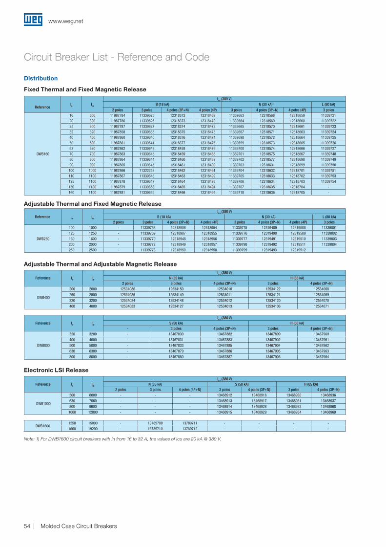
www.weg.net
Molded Case Circuit Breakers54
Circuit Breaker List - Reference and Code
ReferenceIn Im
Icu (380 V)B (18 kA) N (30 kA)1) L (80 kA)
2 poles 3 poles 4 poles (3P+N) 4 poles (4P) 3 poles 4 poles (3P+N) 4 poles (4P) 3 poles
DWB160
16 300 11987784 11339625 12318372 12318469 11339663 12318568 12318659 1133972120 300 11987786 11339626 12318373 12318470 11339664 12318569 12318660 1133972225 300 11987787 11339627 12318374 12318472 11339665 12318570 12318661 1133972332 320 11987858 11339638 12318375 12318473 11339667 12318571 12318663 1133972440 400 11987860 11339640 12318376 12318474 11339698 12318572 12318664 1133972550 500 11987861 11339641 12318377 12318475 11339699 12318573 12318665 1133972663 630 11987862 11339642 12318458 12318476 11339700 12318574 12318666 1133972770 700 11987863 11339643 12318459 12318488 11339701 12318575 12318667 1133974880 800 11987864 11339644 12318460 12318489 11339702 12318577 12318698 1133974990 900 11987865 11339645 12318461 12318490 11339703 12318631 12318699 11339750100 1000 11987866 11322258 12318462 12318491 11339704 12318632 12318701 11339751110 1100 11987867 11339646 12318463 12318492 11339705 12318633 12318702 11339753125 1100 11987878 11339647 12318464 12318493 11339706 12318634 12318703 11339754150 1100 11987879 11339658 12318465 12318494 11339707 12318635 12318704 -160 1100 11987881 11339659 12318466 12318495 11339718 12318636 12318705 -
Reference In Im
Icu (380 V)B (18 kA) N (30 kA) L (80 kA)
2 poles 3 poles 4 poles (3P+N) 4 poles (4P) 3 poles 4 poles (3P+N) 4 poles (4P) 3 poles
DWB250
100 1000 - 11339768 12318906 12318954 11339775 12319489 12319508 11339801125 1250 - 11339769 12318907 12318955 11339776 12319490 12319509 11339802160 1600 - 11339770 12318948 12318956 11339777 12319491 12319510 11339803200 2000 - 11339772 12318949 12318957 11339798 12319492 12319511 11339804250 2500 - 11339773 12318950 12318958 11339799 12319493 12319512 -
Reference In Im
Icu (380 V)N (35 kA) H (65 kA)
2 poles 3 poles 4 poles (3P+N) 3 poles 4 poles (3P+N)
DWB400
200 2000 12534086 12534150 12534010 12534122 12534068
250 2500 12534085 12534149 12534011 12534121 12534069
320 3200 12534084 12534148 12534012 12534120 12534070
400 4000 12534083 12534127 12534013 12534106 12534071
Reference In Im
Icu (380 V)S (50 kA) H (65 kA)
- 3 poles 4 poles (3P+N) 3 poles 4 poles (3P+N)
DWB800
320 3200 - 13467830 13467882 13467899 13467960
400 4000 - 13467831 13467883 13467902 13467961
500 5000 - 13467833 13467885 13467904 13467962
630 6300 - 13467879 13467886 13467905 13467963
800 8000 - 13467880 13467887 13467906 13467964
Distribution
Fixed Thermal and Fixed Magnetic Release
Adjustable Thermal and Fixed Magnetic Release
Note: 1) For DWB1600 circuit breakers with In from 16 to 32 A, the values of Icu are 20 kA @ 380 V.
Adjustable Thermal and Adjustable Magnetic Release
Electronic LSI Release
Reference In Im
Icu (380 V)N (35 kA) S (50 kA) H (65 kA)
2 poles 3 poles 4 poles (3P+N) 3 poles 4 poles (3P+N) 3 poles 4 poles (3P+N)
DWB1000
500 6000 - - - 13468912 13468916 13468930 13468936
630 7560 - - - 13468913 13468917 13468931 13468937
800 9600 - - - 13468914 13468928 13468932 13468968
1000 12000 - - - 13468915 13468929 13468934 13468969
DWB16001250 15000 - 13789708 13789711 - - - -1600 19200 - 13789710 13789712 - - - -

www.weg.net
Molded Case Circuit Breakers 55
Circuit Breaker List - Reference and Code
Reference In Im
Icu (380 V)N (35 kA)
3 poles 4 poles (3P+N)
DWB400
200 1000 12534082 12531407250 1250 12534079 12530983320 1600 12534078 12533771400 2000 12534077 12533775
DWB800
320 1600 13467967 -
400 2000 13467988 -
500 2500 13467989 -
630 3150 13467991 -
800 4000 13467992 -
Reference In Im
Icu (380 V)S (50 kA)
3 poles 4 poles (3P+N)
DWB1000
500 6000 13468912 13468916630 7500 13468913 13468917800 9600 13468914 13468928
1000 12000 13469615 13468929
Reference In Im
Icu (380 V)B (18 kA)3 poles
DWB160
55 275 1134006175 375 1134006285 425 11340063105 525 11340064125 625 11340066140 700 11340067160 800 11340068
Generator
Fixed Thermal and Fixed Magnetic Release
Reference In Im
Icu (380 V)B (18 kA)3 poles
DWB250
105 525 11340071125 625 11340072160 800 11340073200 1000 11340074250 1250 11340075
Adjustable Thermal and Fixed Magnetic Release
Adjustable Thermal and Adjustable Magnetic Release
Disparador Electrónico - LSI

www.weg.net
Molded Case Circuit Breakers56
Circuit Breaker List - Reference and Code
Reference In 3 poles 4 poles
IWB 160125 11340102 -160 11340103 12652603
IWB 250 250 11344866 12652606
IWB 400 400 12530957 12533963
IWB 800630 13468817 13468859800 13468858 13468860
IWB 1000 1000 13468861 13468862
Switch Disconnector
Reference In Im
Icu (380 V)N (30 kA) L (80 kA)3 poles 3 poles
DWB160
25 300 11339864 1133993632 384 11339865 1133993740 480 11339866 1133994850 600 11339867 1133995065 780 11339928 1133995180 960 11339929 1133995295 1140 11339930 11339953
Reference In Im N (35 kA) L (80 kA)
DWB250
80 960 11340029 11340035105 1260 11340031 11340037150 1800 11340032 11340058185 2220 11340033 11340059200 2400 11631304 11631305
Fixed Magnetic Release
Motor
Reference In Im
Icu (380 V)H (65 kA)3 poles
DWB400
150 2250 12534076185 2775 12534075250 3750 12534074320 4800 12534073
DWB800420 6300 13467997500 7500 13468019
Adjustable Magnetic Release

www.weg.net
Molded Case Circuit Breakers 57
Notes

www.weg.net
Molded Case Circuit Breakers58
Global PresenceWith more than 30.000 employees worldwide, WEG is one of the largest electric motors, electronic equipments and systems manufacturers. We are constantly expanding our portfolio of products and services with expertise and market knowledge. We create integrated and customized solutions ranging from innovative products to complete after-sales service.
WEG’s know-how guarantees our molded case circuit breakers DWB is the right choice for your application and business, assuring safety, efficiency and reliability.
Partnership is to create solutions that suits your needs
Competitive edge is to unite technology and inovation
Availability is to have a global support network
Global presence is essential, as much as understanding your needs.

www.weg.net
Molded Case Circuit Breakers 59
Full Circuit Breaker Solutions
Note: 1) MDWH at 220 V AC Icu = 20 kA.
MDW Miniature Circuit
Breaker
Frame 1
Frame 2
2 to 63
70 to 125-Fixed 3
MDWH Miniature Circuit Breaker1)
Fixed1 frame - 101)6 to 63
DW Molded Case Circuit Breaker
160
250
400
800/1000
1600
16 to 160
100 to 250
200 to 400
320 to 1000
1250 to 1600
18 - 80
18 - 80
35 - 65
35 - 65
35
Fixed and ajustable
-
-
Ajustable
100/160
101/161/250
400/630
800
20 to 160
16 to 250
160 to 400
630 to 800
-
AjustableFixed and ajustable
ACW High-Capacity Molded Case Circuit Breaker
800/1600
2000/2500/3200
4000/5000
6300
320 to 1600
800 to 3200
1600 to 5000
2520 to 6300
65
85
100
120
- Ajustable
ABW Open Circuit Breaker
Dimensions(frames)
Currents(A)
ElectronicProtection
ThermomagneticProtection
Breaking capacity Icu @ 380 V ac
85 -150
85 -150
85 -150
100
Ajustable
Know More

WEG Group - Automation Business Unit Jaraguá do Sul - SC - Brazil Phone: +55 47 3276 4000 [email protected] www.weg.net C
od: 5
007
0240
| R
ev: 0
2 | D
ate
(m/y
): 10
/201
7Th
e va
lues
sho
wn
are
sub
ject
to c
hang
e w
ithou
t prio
r no
tice.
For those countries where there is not a WEG own operation, find our local distributor at www.weg.net.
WEG Worldwide Operations
ARGENTINASan Francisco - CordobaPhone: +54 3564 [email protected]
Cordoba - CordobaPhone: +54 351 [email protected]
Buenos AiresPhone: +54 11 [email protected]
AUSTRALIAScoresby - Victoria Phone: +61 3 [email protected]
AUSTRIAMarkt Piesting - Wiener Neustadt-LandPhone: +43 2633 [email protected]
BELGIUMNivelles - BelgiumPhone: +32 67 [email protected]
BRAZILJaraguá do Sul - Santa CatarinaPhone: +55 47 [email protected]
CHILELa Reina - SantiagoPhone: +56 2 [email protected]
CHINANantong - JiangsuPhone: +86 513 [email protected]
Changzhou – Jiangsu Phone: +86 519 [email protected]
COLOMBIASan Cayetano - BogotaPhone: +57 1 [email protected]
ECUADOREl Batan - QuitoPhone: +593 2 [email protected]
FRANCESaint-Quentin-Fallavier - IsèrePhone: +33 4 [email protected]
GERMANYTürnich - Kerpen Phone: +49 2237 [email protected]
Balingen - Baden-WürttembergPhone: +49 7433 [email protected]
Homberg (Efze) - HessePhone: +49 5681 [email protected]
GHANAAccraPhone: +233 30 [email protected]
INDIABangalore - KarnatakaPhone: +91 80 [email protected]
Hosur - Tamil NaduPhone: +91 4344 [email protected]
ITALYCinisello Balsamo - MilanoPhone: +39 2 [email protected]
JAPANYokohama - KanagawaPhone: +81 45 [email protected]
MALAYSIAShah Alam - SelangorPhone: +60 3 [email protected]
MEXICOHuehuetoca - MexicoPhone: +52 55 [email protected]
Tizayuca - HidalgoPhone: +52 77 97963790
NETHERLANDSOldenzaal - OverijsselPhone: +31 541 [email protected]
PERULa Victoria - LimaPhone: +51 1 [email protected]
PORTUGALMaia - PortoPhone: +351 22 [email protected]
RUSSIA and CISSaint PetersburgPhone: +7 812 363 [email protected]
SOUTH AFRICAJohannesburgPhone: +27 11 [email protected]
SPAINCoslada - MadridPhone: +34 91 [email protected]
SINGAPORESingaporePhone: +65 [email protected]
SingaporePhone: +65 [email protected]
SCANDINAVIAMölnlycke - SwedenPhone: +46 31 [email protected]
UKRedditch - WorcestershirePhone: +44 1527 [email protected]
UNITED ARAB EMIRATESJebel Ali - DubaiPhone: +971 4 [email protected]
USADuluth - GeorgiaPhone: +1 678 [email protected]
Minneapolis - MinnesotaPhone: +1 612 3788000
VENEZUELAValencia - CaraboboPhone: +58 241 [email protected]


