128
Molded Case Circuit Breakers, Motor Protection Circuit Breakers, and Motor Circuit Protectors Technical Data

Molded Case Circuit Breakers, Motor Protection Circuit Breakers, and Motor Circuit Protectors
Technical Data


Table of Contents Introduction........................................................................................................................................................................................ 4
Definitions ........................................................................................................................................................................................... 5
Product Range .................................................................................................................................................................................. 8
Product Line Overview .............................................................................................................................................................. 11
Product Specifications
Molded Case Circuit Breakers ................................................................................................................................24
Motor Circuit Protectors ...........................................................................................................................................42
Motor Protection Circuit Breakers .......................................................................................................................52
Accessories
Auxiliary & Alarm Contacts .....................................................................................................................................55
Shunt Trip ..........................................................................................................................................................................58
Undervoltage Release .............................................................................................................................................. 60
Motor Operators ...........................................................................................................................................................62
Residual Current Release Module ...................................................................................................................... 64
Time-Current Curves
Motor Circuit Protectors .......................................................................................................................................... 66
Thermal Magnetic Molded Case Circuit Breakers .....................................................................................76
Electronic Molded Case Circuit Breakers ..................................................................................................... 102
Let-Through Energy Curves [I 2t] .........................................................................................................................................116
Peak Let-Through Current Curves ......................................................................................................................................121

4
What is a Circuit Breaker?What is a circuit breaker? This is the first question to answer in understanding Molded Case Circuit Breakers. The definition of a circuit breaker varies between the standards organizations, but the most commonly used definitions are:
The National Electrical Manufacturers Association (NEMA) defines circuit breakers as “devices designed to open and close a circuit by non-automatic means, and to open the circuit automatically on a predetermined overcurrent without injury to itself when properly applied within its rating.”
The International Electrotechnical Commission (IEC) Standard IEC 60947-2 defines a circuit breaker as “a mechanical switching device, capable of making, carrying and breaking currents under normal circuit conditions and also making, carrying for a specified time and breaking currents under specified abnormal circuit conditions such as those of short-circuit.”
There are also similar definitions, that further identify circuit breakers by type of construction and functionality. Within the IEC specification for circuit breakers, there are several distinctions of types of circuit breakers by classification:
Utilization CategoryInterrupting medium• Air break• Vacuum break• Gas break
Design• Open case• Moulded (molded) case
Method of controlling the operating mechanism• Dependent manual operation• Independent manual operation• Dependent power operation• Independent power operation• Stored energy operation
Type of overcurrent release• Instantaneous• Definite time delay• Inverse time delay
In reviewing the attributes just listed, it is understandable that many people are confused about what type of circuit breaker to use, where to use it, and how to select it properly. In this section, the focus will be placed on the definition, application and selection of Molded Case Circuit Breakers (MCCBs) with an inverse time delay as applied to industrial control panels.
This publication will focus on the application and selection of MCCBs, Motor Protection Circuit Breakers (MPCBs) and Motor Circuit Protectors (MCPs). The primary focus will be on products that are packaged in a molded case design, but much of the information can be applied to other circuit breakers that are commonly found in control panels.
140G Molded Case Circuit BreakersIntroduction to Molded Case Circuit Breakers

5
DefinitionsEach of the product categories we mentioned earlier is packaged in a molded case and confusion develops because of the physical similarity of the products.
The Molded Case Circuit Breaker is a specific type of circuit breaker. NEMA defines circuit breakers as devices designed to open or close a circuit by nonautomatic means, and to open the circuit automatically on a predetermined overcurrent without damage to itself when properly applied within its rating. The term “molded case” simply refers to the construction of the circuit breaker and refers to the fact that the circuit breaker is an assembled unit in a supporting housing of an insulating material.
Within the realm of MCCBs, three distinct product variations exist, each with specific protection properties and uses within the industrial control panel. The main categories are:
Molded Case Circuit Breakers or Feeder BreakersMCCBs are intended to provide overcurrent protection for conductors and equipment by opening automatically before the current reaches a value and duration that will cause an excessive or dangerous temperature in conductors or conductor insulation. Additionally, these devices can serve as the main disconnecting means for a control panel. This protection pertains to low level overcurrent, and short-circuit current. Traditionally these types of circuit breakers are generically described as thermal magnetic devices, though an increasing number of these devices are also electronic circuit breakers which provide the same type of protection, with the exception that the electronics allow the protection curves to be customized to the specific application. In the United States, the National Electrical Code (NEC) defines how this protection is selected in Sections 240-2, 240-3 and 240-4. In Canada there are similar references in the Canadian Electric Code, C22.1-12. For IEC applications, IEC 60204-1 provides guidance for the construction of industrial control panels.
Motor Protection Circuit Breakers Application-specific variations of the MCCB, these breakers combine the short-circuit and isolation functionality of the MCCB with the motor overcurrent protection of a traditional overload relay. These devices are traditionally used in two-component starter applications, with a contactor to control a motor load. MPCBs are UL 489 Listed as circuit breakers and verified as motor overload relays. Allen-Bradley® MPCBs are UL Listed as 100% breakers, allowing utilization of the full range of motor protection provided. Note: most circuit breakers applied in North America are 80% rated, meaning they can only be used continuously at 80% of their thermal rating. Allen-Bradley MPCBs are 100% rated, allowing full use of the circuit breakers’ thermal capacity in motor protection applications.
Motor Circuit ProtectorsAnother application-specific version of the MCCB, the Motor Circuit Protector (MCP) is a magnetic trip only version of the MCCB. These circuit breakers provide no overload protection and, as a result, when applied in motor circuit need to be applied with a controller in order to provide short-circuit and overcurrent protection. In the United States, the MCP is UL Listed with a controller and together they form a combination starter. The advantage of this combination is the choice in overload protection that can be applied to the starter. Listed combinations can include thermal as well as electronic overload relays, providing users with protection that is customized for their application. The MCP can also be provided in several variations, including high magnetic trip versions that allow them to be used with high-efficiency motors, reducing the chance of nuisance tripping due to the characteristic high inrush currents associated with these motors.
Where are each of these breakers used? The diagram below represents a typical multi-starter control panel. Note that the main disconnecting means is an MCCB, which is acting as both the main disconnect and feeder protection. There are several branches within this control panel. Both MCPs and MPCBs are being used to provide the branch a circuit breaker as a device in the case of the MCP, and branch short-circuit protection as well as overload protection in the case of the MPCB.
Branch Motor Circuits Branch Circuits
Motor circuit protection devices with magnetic-only trip unit
Molded case circuit breaker with thermal magnetic protection
Molded case circuit breakers with thermal magnetic protection
Resistive loads (heating elements, lighting, etc.)
contactoroverload relaystarter

6
Breaker Theory and ConstructionWhen used in an industrial control panel application, the purpose of the MCCB is to provide overcurrent protection. This definition can be divided into short-circuit protection and thermal overcurrent protection. A short circuit can range from hundreds of amps to over 100,000 amps, depending upon the power source and where the short circuit would occur in the circuit.
An arc chamber is integral to all MCCBs. This arc chamber will be similar in all forms of the circuit breakers and performs several import functions in providing short-circuit protection. This chamber surrounds the switching contacts within the circuit breaker and the contacts open during a short circuit. The opening of these contacts generates an arc. The arc chamber and its components, the arc chutes and splitter plates, draw the arc away from the contacts, dividing and cooling the arc. Ultimately, this leads to the extinguishing of the arc and the circuit opening and current flow stopping. One of the remarkable elements is that this entire operation occurs in milliseconds, with short-circuit currents that can be 100,000 A or greater, depending upon the available current in the circuit.
Depending upon the design of the circuit breaker and intended short-circuit interruption capability, differences in the construction of the contact assemblies exist. The most commonly used contact assemblies are shown here.
The reverse loop design is used in modern circuit breakers as its design uses the magnetic forces created by current flowing in opposite direction to assist in the opening of the contacts under short-circuit conditions. Additionally, the amount of repulsive force generated is proportional to the value of the short-circuit current being experienced by the circuit breaker. This provides for faster interruption time as the short-circuit currents increase.
Using these magnetic trip units, we are able to provide short-circuit protection that can be represented in a curve as shown above.
This document is not designed to be a reference to circuit breaker design. However, the construction of the arc chamber is being discussed as it is important to understand that MCCBs with a 25 kA interrupting rating will require fewer arc splitters and smaller arc chutes to interrupt a short circuit than will a comparable device rated for 100 kA of interruption. Therefore, when selecting an MCCB for a specific application, it is very important to take into consideration the amount of short-circuit current available and then select the circuit breaker with an interrupting rating sufficient to meet the requirements of the application.
The MCCB also provides thermal protection for the control panel and, as we will see later, the branch circuit. This thermal protection can be provided either through the use of bimetallic heater elements similar to those found in overload relays or through the use of electronics, which simulate the operation of heater element and can provide adjustable overcurrent protection for the application.
Current (A)
10
1.0
0.1
.01
I
Tim
e (s
ec)
Conventional Contact Design
Current FlowMagnetic Force
Reverse Loop Contact Design
Conventional contact design compared to reverse loop contact design.
Example of magnetic time vs. current curve.

7
Trip Curve for a Thermal Magnetic MCCBThe most commonly selected form of thermal protection is the bimetallic version. This works similarly to a traditional overload relay in which a bimetallic element is heated, causing a deflection, which then exerts pressure on a trip bar and causes the circuit breaker to trip.
Trip Curve for an Electronic MCCBAn alternative to using fixed-thermal protection is to use electronic overcurrent protection, which can electronically replicate the function of the mechanical overcurrent device. One of the benefits of using electronic trip units is their ability to tailor the tripping characteristics of the circuit breaker for the application.
The electronic trip unit has the ability to provide advanced protection in the form of additional trip functionality such as adjustable:
Long Time – Allows the long time between 1.05 and ~1.3 x the thermal rating to be delayed, similar to how an adjustable relay changes classes
Short Time – Adjustable short time between thermal and short-circuit
Instantaneous Trip – Adjustable instantaneous short-circuit trip time
Ground Fault – Adjustable time and value of ground fault tripping
In the application section of this introduction we will examine trip curves in greater detail. For now, we are presenting the electronic trip units for the purpose of understanding the scope of a Molded Case Circuit Breaker offering.
Electronic trip units are available in a variety of trip settings. The most common combinations are LSI, LSIG and M-LIV trip settings; therefore a wide variety of options exist for customizing the protection the circuit breaker provide within the control panel.
Rockwell Automation offers a full range of Allen-Bradley Molded Case Circuit Breakers for use in industrial control panel applications. In an effort to simplify the application of MCCBs and their complimentary products, this application guide will help you properly select and apply circuit breakers used in an industrial control panel.
2x 5x
3 min
10 sec
Tim
e
MaximumTime
MinimumTime
0.1 kA 1 kA
Current
10 kA 100 kA
1E2 s
0.1 s
10 s
100 s
1E3 s
1E4 s
Tim
e (s
ec)
L
SG
I
3x 40x
1 min
0.01 sec
Tim
e MagneticAction
ThermalAction
Using the bimetallic model, we can provide a thermal protection curve as shown at left.
Combining the short-circuit and overcurrent protection provides us with a protection curve that looks like this.
L – Overcurrent Protection Long Time Delay
S – Short-circuit Protection Short Time Delay
I – Short-circuit Protection Instantaneous Trip
G – Ground Fault Protection

8
Product Range
140G Molded Case Circuit Breaker Thermal ProtectionAs previously described, MCCBs provide thermal overcurrent protection in addition to short-circuit protection. MCCBs provide this protection by using mechanical means with heater elements, or by using electronics to detect current flow and model the associated heat generated by the current.
When electronic MCCBs are applied, the ability to adjust the thermal trip rating to shape the trip curve is available and the result is that there are fewer trip units required to cover a wider range of current. Note: while a trip unit may have the capability of protecting the current range, in many cases a rating plug is used to limit the range of adjustability.
The table below illustrates the available thermal magnetic and electronic trip units and adjustment ranges available with the 140G family of MCCBs.
Amperes
10 15 16 20 24 25 30 32 35 40 45 50 56 60 63 64 70 77 80 87 90 100 105 110 112 120 122 125 140 150 157 160 175 200 210 225
G T-M • • • • • • • • • • • • • • • • • • (**)
H Ther
mal
Mag
netic
• • • • • • • • • • • •o
oo
oo
o (*)
Elect
roni
c
(*)I T-M • • • • • • • • • • • • •
J Ther
mal
Mag
netic
• • • • • • • • •o
oo
oo
oo
oo
o o
Elect
roni
c
K
T-M
Elect
roni
c
M
T-M
Elect
roni
c
N/NS
Elect
roni
c
R
Elect
roni
c
• Denotes Fixed Thermal and Fixed Magnetic.o Denotes Adjustable Thermal and Adjustable Magnetic.(*) IEC only.(**) IEC only. G-Frame is Adjustable Thermal.

9
Amperes
240 250 252 280 300 320 350 400 420 480 560 600 630 800 900 1000 1200 1300 1400 1500 1600 1700 1800 1900 2000 2100 2200 2400 2500 2600 2700 2800 2900 3000
oo
oo

10
Applying Molded Case Circuit Breakers to North American GuidelinesThe MCCB is most commonly used as either a feeder breaker or a single circuit breaker where disconnecting, short-circuit, and thermal protection functionality is required. When selecting an MCCB, the following items need to be taken in to consideration:
• Application voltage• Available short-circuit current• Amperage of the load or wiring to be protected
Additionally, local code requirements will also need to be taken into consideration and may ultimately affect the type and functionality of the MCCB selected.
MCCB• Magnetic and Thermal Trip Currents may be
fixed or adjustable• Must be sized per NEC/CEC rules• May be used for motor circuits, but 140MG (MCP) is first choice• Motor Current (thermal rating)
– ≤ 250% motor FLA
– ≤ 300% for motors ≤ 100 A if the circuit trips on start
– ≤ 400% for motors ≥ 100 A if the circuit breaker trips on start
• Magnetic Trip Current is generally set at 1000% (10x) of circuit breaker thermal ratings
• May be UL Listed as part of UL 508/UL 60947-4-1• May also be used for motor control-circuit transformers,
but Bulletin 1489 MCBs are the first choice
Motor Protection Circuit Breakers While globally these devices are considered motor protection circuit breakers, in North America they are defined as manual Type E self-protecting combination motor controllers:
• Sized at 100% of the motor full-load current (FLA)• Motor current setting is adjustable (thermal rating)• IEC & UL/CSA calibration requirements require overload to trip at
120 & 125% FLA• Motor is able to run into the Service Factor when
set at 100% of the motor current• Magnetic Trip Current setting is adjustable (magnetic rating)• Adjustable at 1300% (13x) highest motor current setting
on circuit breaker• Higher Magnetic Trip Current settings are available if circuit
breaker trips on start (140M-C2T-***)• Example of an MPCB using 140M-C2E-C10:
– Motor Current is adjustable from 6.3…10 A
– Set at 100% FLA for proper motor protection
– Magnetic Trip Current is fixed at 130 A
– This is where circuit breaker begins to trip in a “short-circuit” condition
• Motor Protection Circuit Breakers are relatively new to the North American market
• NEC/CEC (Canadian Electrical Code) do not specifically recognize this classification of circuit breaker and, therefore, do not describe how to size them (e.g. 100% FLA sizing)
Motor Circuit Protectors• Motor current setting (thermal) is not specified by NEC/CEC• MCPs are magnetic only• Thermal capability should be greater than or equal to motor
FLA and less than or equal to overload relay setting• Motor overload protection must be provided separately• MCPs are UL Recognized• Must be tested and listed with specific contactors
and overloads• UL Listing is obtained as part of UL 508/UL 60947-4-1• Magnetic trip current is adjustable• Adjustability is required by UL489 standard• Must be sized per NEC/CEC rules
– ≤ 800% motor FLA for standard efficiency motors
– ≤ 1300% motor FLA allowed if motor will not start
– ≤ 1100% motor FLA for high efficiency motors
– ≤ 1700% motor FLA allowed if motor will not start
• MCPs are the most popular choice for motor circuits in the North American market
• Used in combination starters and Motor Control Center unit inserts (buckets) for many years
• Provide choice in overload protection

11
Product Line Overview Rockwell Automation offers a complete line of Allen-Bradley Molded Case Circuit Breakers, Motor Circuit Protectors and Motor Protection Circuit Breakers.
In the MCCB family there are eight frame sizes of MCCBs, from 15 A through 3000 A, with dual-rated EN/IEC 60947-2 and UL489 breakers in 3- and 4-pole configurations. All frame sizes feature full sets of accessories as well as common accessories, which allows reduced inventory and maximum flexibility.
In the MCP family of products, there are seven frames, ranging from 3 A through 1200 A. The MCPs, like the MCCBs, share the same accessories and provide the same flexibility. In the MPCB range of products there are three frames ranging from 25 A through 150 A, which share the same accessories as MCPs and MCCBs.
* 160 A IEC only
MCCB Portfolio Overview
Frame Reference G H I J K M N/NS RMolded Case Circuit Breakers
• Bulletin 140G globally rated MCCBs
• UL 489, EN 60947-2, CE, CCC
• Feeder circuits and disconnects
• 3- and 4-pole versions
15…125 A* 15…125 A* 60…225 A 25…250 A 120…400 A 240…800 A 480…1200 A 800…3000 A
Motor Protection Circuit Breakers
• Bulletin 140MG globally rated MPCBs
• UL 489, EN 60947-2, CE
• Branch protection, 2-component starters
• 3-pole versions
25…100 A 40…150 A
Motor Circuit Protectors
• Bulletin 140MG globally rated MCPs
• UL 489, EN 60947-2, CE
• Branch protection, 3-component starters
• 3-pole versions
3…125 A 3…125 A 100…150 A 150…250 A 300…400 A 600…800 A 1200 A

12
Auxiliary Contacts (AX)Auxiliary contacts perform the function of electrically signaling the circuit breaker’s operating status. The auxiliary contacts change state when the circuit breaker is opened, closed, or tripped.
Auxiliary contacts indicate the ON/OFF status of the MCCB. The 140G auxiliary contacts are changeover contacts (Form C).
Alarm Contacts (AL)Alarm Contacts (AL) are a special form of auxiliary contacts that indicate the trip status of the MCCB due to:
• Trip due to overload• Trip due to short circuit• Trip due to residual current (if equipped)• Trip due to shunt trip and/or undervoltage release (if equipped)• Trip initiated by pressing the “test” button
After initial alarm contact change of state, the Alarm Contacts (AL) change state only when one of the above conditions occur. Manual operation of the breaker to Off does not affect the state of these contacts. The 140G Alarm contacts are changeover contacts (Form C).
Combination Auxiliary Alarm ContactsAuxiliary/Alarm contacts include contacts to perform both the Auxiliary Contact (AX) function and the Alarm Contact (AL) function.
24
24
AX2
22
22
21
21
96
98
98
95
95
AL1
96
24
24
AX2
22
22
21
21
9698
9895
95
AL1
96

13
DIN Rail AdaptersIn many applications, the ease with which an MCCB can be installed via the use of a DIN Rail adapter. Rockwell Automation provides DIN Rail adapters as accessories for use with its 140G G-, H-, I- and J-Frame breakers.
Flex Cable OperatorsFlexible Cable Operators are useful accessories when installing a circuit breaker in a flanged enclosure and the MCCB needs to be controlled externally. Traditionally in North America, flange operators that consist of operating rods or special mounting plates for the breakers have been used. In each case, the circuit breaker must be mounted directly or nearly directly behind the external handle, which is located on the flange. This type of installation is reliable; however, the positioning of the circuit breaker is less than ideal in terms of working room, especially in small enclosures.
The Flexible Cable Operator uses a similar flange-mounted operating handle to control the MCCB; however, rather than operating rods, the breaker is operated by a flexible cable, which provides flexibility in the circuit breaker placement. In many industrial control panels, incoming power to the panel may actually be on the hinged side of the panel and when using traditional flange-mounted operators, the main feeder wires would need to be routed across the panel to the line side of the MCCB. Using a flexible cable-operated MCCB allows the MCCB to be installed closer to the incoming feeder wires and can significantly improve the installation of the control panel.
Another application where Flexible Cable Operators are used is in conjunction with busbar mounting systems installed within an industrial control panel. When an MCCB is being used on the busbar system as the main disconnect or feeder protector, the location of the feeder breaker isn’t restricted to the area behind the flange.

14
End Cap KitsAll 140G MCCBs are furnished with end caps mounted on the circuit breaker as standard. Replacement end cap kits are available.
Many customers prefer to use a “crimp-on” ring lug (ring tongue terminal) or forked terminal as the wire termination method to the MCCB. Others prefer wire connection to a terminal lug. A broad selection of terminal lugs are available to meet specific application requirements.
The replacement end cap kit consists of a captive nut and bolt or termination screw, which allows for the termination of wires without the need to use terminal lugs.
Terminal CoversThe terminal shield prevents accidental contact with live parts, they also provide phase to phase insulation.
Ingress ProtectionThe table indicates the degrees of protection against intrusion and accidental contact per IEC 60529 Standard.
Location Without Terminal Covers With High Terminal Covers (&)
A IP40** –
B IP20* IP40*
C – IP40†
* G through M frames. ** Also with direct or variable depth rotary operator. † After installation. (&) High terminal covers have a height of 60 mm and are designated with a suffix “H” in the catalog number, (i.e. 140G-G-TC3H).
Motor OperatorsThe operating mechanism enables remote opening and closing of the circuit breaker and is particularly suitable for use in power supply network supervisory control systems. It comes complete with a padlock device.
The motor operating mechanism is fitted on the front of the circuit breaker as an alternative to the front flange or rotary operating mechanism. Motor-operated circuit breakers are normally used in applications where switching is done infrequently and generally are not used to replace contactors that are applied in series with the circuit breaker.
A
B
C

15
Shunt TripShunt trips allow the circuit breaker to be opened using an electric command (opening release). The shunt trip is housed and fitted in a slot within the circuit breaker.
Shunt trips are used in applications where a remote signal to open or isolate a circuit is required.
Undervoltage ReleaseUndervoltage releases allow the circuit breaker to be opened using a change in the voltage of the power supply to the circuit breaker terminals. The undervoltage release is fitted in a slot within the circuit breaker. Undervoltage releases work when the application voltage is reduced below 75% of the rating of the release unit voltage rating.
Use of undervoltage releases can protect a system against low voltage, particularly when running or starting motors, by removing power to the circuit by opening the circuit breaker in low-voltage situations. In some applications, the undervoltage release can be used to quickly remove power to a machine or machines by opening a push button contact, wired in series with the undervoltage releases.
Rotary OperatorsWhen MCCBs are installed as the main or feeder circuit breaker in an industrial control panel and a non-flanged enclosure is used, a common means for operating the circuit breaker is through the use of a rotary operator mechanism. The use of a rotary operator converts a rotary motion to a vertical motion that “toggles” the MCCB. In this situation, the rotary operator kit would consist of:
• External operating handle • Operating shaft • Circuit breaker mounted rotary operating mechanism
Using these kits allows external operation of the circuit breaker with the capability of turning the circuit breaker on/off, and even resetting the circuit breaker without having to open the enclosure. Traditionally, these kits are sold with an operating shaft that allows the customer to use the kit with enclosures of various depths. The operating handles will also provide status indication when the circuit breakers trip.

16
NFPA 79 OperatorsA NFPA 79-compliant Internal Rotary Operating Handle Kit for Bulletin 140G Molded Case Circuit Breakers (MCCBs), Bulletin 140MG Motor Circuit Protectors (MCPs), and Bulletin 140MG Motor Protection Circuit Breakers (MPCBs) is available to address current requirements of the NFPA 79 standard. The NFPA 79 kits are available for G-, H-, I-, J-, K-, M- and N-Frame Circuit Breaker product lines.
Compliance with the current NFPA 79 standard enables operators to maintain control of the main disconnecting means when the door is open; an issue for rotary-operated through-the-door disconnect switches and circuit breakers alike.
This standard requires that the rotary main disconnecting means to be operable without the use of accessory tools or devices (independent of door position) and restates the requirement for an interlocking provision to prevent the closing of the disconnecting means while the enclosure door is open, unless the interlock is operated by a deliberate action. Without this requirement, rotary operated devices may have a shaft protruding from the panel when the door is open. If the panel is powered and it is necessary to turn power off, it is difficult to de-energize the panel by the operating shaft alone. This standard is to reduce the possibility of personnel not being able to turn an energized panel off with the door opened.
Why is This Relatively Simple Product Important to You?The trend in the market is obviously moving toward building smaller and less-expensive control panels. To achieve this, many panel builders and OEMs have moved toward using rotary operators because they are easier to install and the non-flanged enclosure is significantly less expensive. With the introduction of this internal handle, customers can now comply with the NFPA 79 requirement and use the less-expensive, non-flanged enclosure with circuit breakers.
Applications Where NFPA 79 Compliance is Required as an UpgradeFrom an installation perspective, the internal handle replaces the existing operating shaft. Externally, the same 140G handle is used. In the case of an existing 140G installation, installing the kit can be as simple as removing the existing operating shaft, measuring it, and then cutting the new internal operating handle shaft to the same length. It is then installed in place of the existing operating shaft.
Easy to Use, No-Tools-Required Internal Handle OperationWhen the door is open, the kit provides an internal handle with a positive grip, allowing users to operate the breaker. If the enclosure were opened using the defeater on the external handle with the circuit breaker on, the user could then turn the breaker off using the internal handle, rather than using a tool to rotate the operating shaft.
Compliance with “Deliberate Action Required”Finally, the handle complies with the NFPA 79 requirement to: “Prevent closing of the disconnecting means while the enclosure door is open, unless an interlock is operated by deliberate action.” The internal handle must be pulled out before it can be turned, otherwise the handle itself will just ratchet on the shaft.

17
Phase BarriersThese allow the insulation characteristics between the phases at the connections to be increased. Phase Barriers provide additional electrical clearance between each phase when special connections extend past the circuit breaker housing. They are mounted from the front, even with the circuit breaker already installed.
Mechanical Accessories
Terminal LugsMechanical Terminal Lugs may be used to terminate line and load wiring to the MCCB. The 140G product line includes, as standard, the capability to terminate wiring using customer furnished “crimp-on” ring lug (ring tongue) or forked lug termination.
For customers who prefer terminating wiring to Mechanical Terminal Lugs, the 140G line offers a variety of mechanical terminals lugs to match the frame and application wiring.
Multiple tap terminal lugs are available for those customers terminating multiple wires to a MCCB pole, either to line or load connection. Use of a multi-tap connection can save on panel space, making wiring easier due to using ( multiple) smaller diameter wire. For applications following the UL guidelines for panel short-circuit current rating (SCCR), the use of multiple wire termination on the load size permits the termination to be rated at the SCCR level of the circuit breaker, which may allow a higher SCCR than may be available using a separate power distribution block.

18
Padlock AttachmentsPadlocking hasps are available for the range of MCCB line. This attachment allows the user the ability to padlock the MCCB in the off position. It prevents operation of the circuit breaker when the attachment and a padlock are in place.
Using Trip CurvesOne of the most common questions encountered after “How is an MCCB properly sized?” is “How do I interpret the trip curves provided?”
A logical starting point is to explain what the curve actually is. The curve is a representation of how the circuit breaker will react to overcurrents and short-circuit currents. It should be noted that the curve is determined by a specific set of test conditions, and as such, the curve should be used as a guideline; real world deviations from the test criteria may alter the individual results as compared to the curve.
Time-Current Curves for 140G-G thermal magnetic Molded Case Circuit Breakers
For all 4 pole 140G MCCB and Molded Case Switches the neutral is the left outside pole, as shown in the illustration.
Hot Trip
Cold Trip
Neutral PoleWhen applying 4 pole MCCB, the neutral pole is rated at 100% for thermal magnetics, and adjustable 100%, 50% or 0% for electronics.

19
Reverse-Fed Circuit BreakerDue to physical equipment arrangements in panelboards, switchboards, and industrial control panels, it is often desirable to reverse feed a molded case circuit breaker. For this application, the circuit breaker must be tested and listed accordingly.
Please note that all Bulletin 140G circuit breakers may be reverse fed. When reverse feeding these devices, the line and load side terminals need to be identified properly.
Note: Maximum voltage for reverse fed.
Reverse Fed
Bulletin 140G & 140MGMaximum AC Voltage [V]
UL/CSA IEC
G 600Y/347 690
H 480 480
I 600Y/347 690
J 600 600
K 600 690
M 600 690
N, NS 600 690
R 600 690
Note: The NEC Article 404.7 states “Where these switch or circuit breaker handles are operated vertically rather than rotationally or horizontally, the up position of the handle shall be the (on) position.” Refer to applicable codes and standards for specific application requirements.
Motor
T1 T2 T3
L3 L2 L1
Interrupting RatingsThe maximum amount of fault current supplied by a system can be calculated at any point in that system. One rule must be followed for applying the correct circuit breaker. The interrupting rating of the breaker must be equal to or greater than the amount of fault current that can be delivered at that point in the system where the breaker is applied. The interrupting rating of the breaker is the maximum amount of fault current it can safely interrupt without damaging itself. A breaker’s interrupting rating always decreases as the voltage increases. Interrupting rating is one of the most critical factors in the breaker selection process.
CertificationsTo provide customers with third-party assurance that Rockwell Automation® MCCBs meet industry standards, our circuit breakers comply with various global standards. The Bulletin 140G MCCB and 140MG MCP and MPCBs comply with UL, CSA and IEC standards and as such, are UL Listed, CSA Certified, and CCC Certified.
Other certifications exist for the family of MCCBs. The certification of these products is an ongoing process and additional ratings and certifications are continually being pursued. For information about compliance with a particular standard, contact your local Rockwell Automation sales office or Allen-Bradley distributor.
In each of the product sections, the latest certifications at the time of publication are listed for the specific product type.

20
Selecting a Circuit Breaker, When Application is to Follow U.S. GuidelinesThe next step is selecting a breaker for use in an industrial control panel. In the following section we will focus on the MCCB for use as a feeder and as a branch circuit protective device.
Selecting The MCCB for Use as The Main Disconnect or FeederA typical industrial control panel is a feeder circuit as defined by the NEC, where a feeder is composed of the wires between the service entrance of the panel or line side of the MCCB and the line side of the branch protective devices.
In many industrial control applications, motor control is involved. In that case, the application must then follow Article 430 of the NEC, which states that breakers for feeders having mixed loads, e.g. heating (lighting and heat appliances) and motors should have ratings suitable for carrying the heating loads, plus the capacity required by the motor loads.
For motor loads, Article 430 states that breakers for motor feeders shall have a rating not greater than the sum of the highest breaker rating of any of its branches and the full-load currents of all other motors served by the feeder.
Feeder Breaker Thermal Rating Selection ExampleThis assumes that the circuit breaker selected has a voltage rating equal or greater than the application and that the interrupting rating is equal or greater to the available short-circuit current. The panel contains a main feeder breaker supply with three motor branch circuits.
In our application, the feeder is supplying a 3-motor system at a voltage of 480V.
• Motor 1 is 10 Hp. Current value from Table 430.250 of the NEC is 14 A.
• Motor 2 is 5 Hp. Current value from Table 430.250 of the NEC is 7.6 A.
• Motor 1 is 5 Hp. Current value from Table 430.250 of the NEC is 7.6 A.
Calculation of panel wiring includes:• For single motors. Per [430.22], size motor branch circuit
conductors no smaller than 125 percent of the motor FLC rating listed in Table 430.147 or 430.148 (Figure 430-4). Size the branch circuit short-circuit and ground-fault protection device per 240.6(A) and 430.52(C)(1) Ex. 1.
• For multiple motors. Per [430.24], size multiple motor conductors as follows. First, multiply the full-load current rating of the highest-load motor by 1.25. Then, add up the full-load current ratings of all the other motors in the group. Add these two numbers. That’s your motor load for calculating ampacity. Add any other loads on that conductor, to calculate total conductor ampacity.
Current Calculation is:
Motor 1 (14 A* 1.25) 17.5 A Motor 2 7.6 A Motor 3 7.6 A Total 32.7 A
Since the total load comes to 32.7 A and there is not a commercially available breaker available for 32.7 A, the NEC allows the next largest standard-sized breaker to be used. Therefore, a 35 A MCCB could be selected to protect this control panel. Note: each motor branch would also need protection.

21
Thermal Magnetic Circuit Breakers Used as Branch Short-circuit DevicesIt is also possible to use an MCCB as a branch protective device for a motor load, and while we will show the calculation for applying an MCCB in this manner, there are other circuit breakers, such as the MCP and MPCB, that are better suited for this application. After the calculation for sizing is completed, it should be apparent that even though this is technically correct, in some cases, the motor protection and wire protection can be less than ideal.
Per NEC Article 430.52(B), the motor branch circuit short-circuit and ground fault device shall be capable of carrying the starting current of the motor. Further, 430.52(C) indicates that the protective device that has a rating or setting not exceeding the value calculated according to the values given in Table 430.52 shall be used. In the case of an inverse time MCCB, such as the 140G, the calculation for the maximum setting or rating of the protective device is 250% of the motor being protected.
Example
An MCCB is being used to protect a branch motor circuit with a 10 Hp 460V motor. Using Table 430.250 of the NEC, a value of FLC of 14 A is supplied for this motor.
Calculating the maximum branch circuit protective device rating or setting is: 14 A * 250% = 35 A
Therefore, the maximum size MCCB that could be used in this example is 35 A. This is the maximum rating and therefore smaller devices could be selected for this application. A point to consider is that generally MCCBs have a magnetic trip of approximately 10X the rating of the MCCB. When starting, motors usually exhibit an inrush characteristic of 6 to 10 times the full load rating of the motor, depending on the type of motor being used. In this case, the circuit breaker trip point is approximately 350 A and the motor starting current of locked rotor current is approximately 140 A if a 10x ratio of running to starting current is assumed. A smaller breaker could be selected without concern for nuisance tripping. In that case, there may be more concern about the thermal protection provided by the circuit breaker being based on a 35 A breaker with only a 14 A load. The motor and the wiring may not be adequately protected if larger wire isn’t selected or if a motor overload relay is not used.
Branch Motor Circuits Branch Circuits
Motor circuit protection devices with magnetic-only trip unit
Molded case circuit breaker with thermal magnetic protection
Molded case circuit breakers with thermal magnetic protection
Resistive loads (heating elements, lighting, etc.)
contactoroverload relaystarter

2222
MCCB Application and SizingThe Bulletin 140G MCCBs are traditionally used for protection of branch and feeder circuit in an industrial control application. In the role of a feeder circuit breaker, the MCCB provides isolation and short-circuit protection for the panel and thermal protection for the feeder wires and as a branch circuit breaker provides the same protection for the branch wires in the panel. For illustrative purposes, the feeder will be shown at the wiring from the load side of the main or feeder MCCB to the line connection of the branch short-circuit protective devices to which the feeder is supplying power.
The following example is a generic interpretation of the US National Electrical Code (NEC), and should be used only as a reference for applying the MCCB. Final authority regarding the sizing and components used is governed by local and/or national electrical standards and the Jurisdiction Having Authority. Consult these standards before installing or designing any electrical system using short-circuit protective devices (SCPDs).
While this discussion is not intended to be a comprehensive guidebook to designing industrial control panels, we will present several categories of typical applications where a feeder SCPD device will be applied:
• A panel where only motor loads are being fed by the breaker
• A panel where fixed loads are being fed by the breaker
• A panel where mixed loads are being protected by the feeder breaker
In all cases, the examples given here are for reference and users should reference their local electrical code requirements, as they may vary from location to location. The applier should verify that their selection and installation complies with local codes, regulations, and/or standards.
A feeder is composed of the conductors of a wiring system between the service equipment or the generator switchboard of an isolated plant and the branch circuit overcurrent device.
NEC Article 220 states:Where a feeder supplies continuous loads or any combination of continuous and noncontinuous loads, the rating of the overcurrent device shall not be less than the noncontinuous load plus 125% of the continuous load. Exception: Where the assembly including the overcurrent devices protecting the feeder(s) are listed for operation at 100% of their rating, neither the ampere rating of the overcurrent device nor the ampacity of the feeder conductors shall be less than the sum of the continuous load plus the noncontinuous load. Only breakers listed for 100% application, and so labeled can be applied under the exception (for example N Frame and R Frame 140G’s that are specifically marked and rated 100%). Breakers without a 100% application listing and label are applied at 80% of rating.
NEC Article 430 states:Breakers for feeders having mixed loads; e.g., heating (lighting and heat appliances) and motors, should have ratings suitable for carrying the heating loads plus the capacity required by the motor loads…breakers for motor feeders shall have a rating not greater than the sum of the highest breaker rating of any of its branches and the full load currents of all other motors served by the feeder.
A molded case circuit breaker is rated in rms amperes at a specific ambient temperature. This ampere rating is the maximum continuous current it may carry in the ambient temperature for which it is calibrated. To minimize the need for derating, Allen-Bradley thermal magnetic breakers are calibrated for an ambient temperature of 40 °C (104 °F), which is the average temperature within an enclosure. If the enclosure ambient temperature is known to exceed 40 °C, the breaker used should either be specially calibrated for that temperature, or be derated accordingly.
80% Continuous RatedAll 140G Molded Case Circuit Breakers are rated for 80% continuous load unless marked for 100% loads. The NEC requires that only 100% rated continuous load be marked special with the load designation. In all general applications the unmarked circuit breaker is to be applied at no more than 80% continuous load of its rated current (I
n). Typically 100% rated current MCCBs are
devices with electronic trip units. The 140G product line has 100% rated electronic trip MCCBs. Visit www.rockwellautomation.com for specific devices.
Cable SelectionUL Listed circuit breakers rated 125 A or less shall be marked as being suitable for 60 °C (140 °F), 75 °C (167 °F) only or 60/75 °C (140/167 °F) wire. All Allen-Bradley breakers rated 125 A or less are marked for 60/75 °C wire. All UL Listed circuit breakers rated over 125 A are suitable for 75 °C conductors. Conductors rated for higher temperatures may be used, but must not be loaded to carry more current than the 75 °C ampacity of that size conductor for equipment marked or rated 75 °C, or the 60 °C ampacity of that size conductor for equipment marked or rated 60 °C. However, the full 90 °C (194 ˚F) ampacity may be used when applying derating factors, so long as the actual load does not exceed the lower of the derated ampacity or the 75 °C or 60 °C ampacity that applies.

2323
Unusual Operating Conditions
Operation below 0 °CBulletin 140G MCCBs may be applied in ambient temperatures (near the MCCB within an enclosure) below 0 °C. Applications below 0 °C must consider the possibility of ice forming within or on the MCCB and interfering with the internal or external operating mechanisms. All ratings below 0 °C are based on the absence of freezing water or other elements.
Trip Unit TemperaturesThermal magnetic circuit breakers are temperature sensitive. At ambient temperatures below 40 °C (104 °F), circuit breakers may carry more current than their continuous current rating. Nuisance tripping is not a problem under these lower temperature conditions, although consideration should be given to closer protection coordination to compensate for the additional current-carrying capability. In addition, the actual mechanical operation of the breaker could be affected if the ambient temperature is significantly below the 40 °C standard.
For ambient temperatures above 40 °C, breakers should carry less current than their continuous current rating. Under this condition, the circuit breaker should be derated for the higher ambient temperature.
Electronic trip units are insensitive to ambient temperatures within a certain temperature range. The temperature range for most electronic trip units is -25 °C…+70 °C (-13 ˚F…+158 ˚F). Allen-Bradley MCCBs are designed to include temperature protective circuits that initiate a tripping operation and provide self-protection, should the internal temperature rise to an unsafe level.
Circuit Breaker TemperaturesThe temperature of the air immediately surrounding a circuit breaker is the ambient temperature. All Allen-Bradley standard breakers are calibrated to a 40 °C ambient temperature. For any ambient temperature application significantly above or below 40 °C, it is recommended that rerating of the circuit breaker be considered or Rockwell Automation be consulted about any possible re-rating.
AltitudeLow voltage circuit breakers must be derated for voltage and interrupting rating at altitudes above 2000 m (6560 ft) above sea level. The thinner air at higher altitudes reduces cooling and dielectric characteristics compared to the denser air found at lower altitudes.
Use the following tables to derate as appropriate.
Voltage Rating Operational Voltage U
e [V]
Altitude 2000 m (6560 ft)
3000 m (9840 ft)
4000 m (13,120 ft)
5000 m (16,400 ft)
All Frames 100% 90% 79% 67%
Current Rating Rated Uninterrupted Current I
u [A]
Altitude 2000 m (6560 ft)
3000 m (9840 ft)
4000 m (13,120 ft)
5000 m (16,400 ft)
All Frames 100% 98% 93% 90%
Unusual Mounting ConfigurationsGenerally, circuit breakers may be mounted in any position, up or down, horizontal or vertical, without affecting the tripping characteristics or interrupting rating. However, mounting circuit breakers in a vertical position with the ON position other than UP will be in violation of Article 240-81 of the NEC.
TropicalizationThe 140G/MG Circuit breakers are tested in compliance with IEC Standards, making these devices suitable for hot-humid conditions defined in IEC 60721-2-1, climatograph 8. These devices include:
• Moldings of glass fiber reinforced synthetic resins • Metallic parts treated for anti-corrosion• Zinc plating protected by a conversion layer
(hexavalent-chromium free) (e.g. RoHS compliant) • Electronic circuits protected for anti-condensation
Electromagnetic CompatibilityThe 140G/MG Circuit Breakers electronic trip units and electronic residual current releases are in compliance with EN 60947-2 Appendix B and Appendix F and European Directive No. 2004/108/EC regarding EMC – electromagnetic compatibility.
Maintenance Mode (MM)Maintenance Mode (MM) offers a preset set of protection parameters. MM allows systems testing when the molded case circuit breaker is energized or ON. This feature is a manual adjustment on the molded case circuit breaker, via a DIP switch. Preset values for Maintenance Mode are indicated in the selection guide for each frame size.

24
MCCB Performance Characteristics
Visit our website: www.rockwellautomation.com Publication 140G-TD100B-EN-P
Bulletin 140G
Product SpecificationsMolded Case Circuit Breakers
G-Frame H-Frame I-FrameMaximum Rated Current [A] 125/160 o 125/160 o 225
Rated Insulation Voltage, Ui IEC [V] 800 1000 800
NEM
A, U
L, C
SA
Interrupting Rating Code j G2 G3 G6 H2 H3 H6 H0 H15 I2 I3
240V 50/60 Hz (AC) [kA] 50 65 100 65 100 150 200 200 50 65
480V 50/60 Hz (AC) [kA] 25 35 65 25 35 65 100 150 25 35
600Y-347V 50/60Hz (AC) [kA] 10 14 25 10 10
600V 50/60 Hz (AC) [kA] 14 18 25 35 42
(DC) 250V – 2 Poles in Series n [kA] 35 42 50 35 50 65 75 85 25 35
(DC) 500V – 2 Poles in Series n [kA]
(DC) 500V – 3 Poles in Series n [kA] 35 50 65 75 85
(DC) 500V – 4 Poles in Series n [kA] 35 50 50
(DC) 600V – 3 Poles in Series n [kA]
IEC
6094
7-2
Rated Ultimate Short-circuit Breaking Capacity, Icu
220-230V 50/60 Hz (AC) k [kA] 65 85 100 65 85 100 150 200 50 85
380V 50/60 Hz (AC) [kA] 36 50 70 36 50 70 120 150 30 50
400-415V 50/60 Hz (AC) [kA] 36 50 70 36 50 70 120 150 36 50
440V 50/60 Hz (AC) k [kA] 36 50 65 30 36 50 60 70 20 40
500V 50/60 Hz (AC) [kA] 30 36 50 20 25 30 36 50 13 20
525V 50/60 Hz (AC) [kA] 22 35 35 10 12 15 18 20 5 6
690V 50/60 Hz (AC) [kA] 6 8 10 10 12 15 18 20 5 8
(DC) 250V – 2 Poles in Series n [kA] 36 50 70 36 50 70 85 100 36 50
(DC) 500V – 2 Poles in Series n [kA]
(DC) 500V – 3 Poles in Series n [kA] 36 l 50 l 70 l 36 50 70 85 100 36 50
(DC) 750V – 3 Poles in Series n [kA]
Rated Service Short-circuit Breaking Capacity, Ics
220-230V 50/60 Hz (AC) [kA] 75% (50) 75% 75% 100% 100% 100% 100% 100% 75% 50%
380V 50/60 Hz (AC) [kA] 100% 100% 75% 100% 100% 100% 100% 100% 75% 50% (27)
400-415V 50/60 Hz (AC) [kA] 100% 75% 50% 100% 100% 100% 100% 100% 75% 50% (27)440V 50/60 Hz (AC) [kA] 50% 50% 50% 100% 100% 100% 100% 100% 75% 50%
500V 50/60 Hz (AC) [kA] 50% 50% 50% 100% 100% 100% 100% 100% 75% 50%
525V 50/60 Hz (AC) [kA] 50% 50% 50% 100% 100% 100% 100% 100% 75% 50%
690V 50/60 Hz (AC) [kA] 75% 50% 50% 100% 100% 100% 100% 75% 75% 50%
(DC) 250V – 2 Poles in Series n [kA] 100% 75% 75% 100% 100% 100% 100% 100% 100% 75%
(DC) 500V – 2 Poles in Series n [kA]
(DC) 500V – 3 Poles in Series n [kA] 100% 75% 75% 100% 100% 100% 100% 100% 100% 75%
(DC) 750V – 3 Poles in Series n [kA]
Mechanical Life [No. of Operations] 25000 25000 25000
[Operations per Hour] 240 240 240
Electrical Life @ 415V (AC) [No. of Operations] 8000 8000 8000
[Operations per Hour] 120 120 120
Wire Temperature Rating m [˚C] Cu 75 ˚C Cu 75 ˚C Al or Cu 75 ˚C
Ambient Temperature w/out derating ˚F [˚C] 104 ˚F [40 ˚C] 104 ˚F [40 ˚C] 104 ˚F [40 ˚C]
Storage Temperature ˚F [˚C] -40...176 ˚F [-40…+80 ˚C] -40...176 ˚F [-40…+80 ˚C] -40...176˚F [-40…+80 ˚C]
Dimensions 3 Pole [mm] 76.2x70x130 90x82.5x130 105x70x150
[Width/Depth/Height] 4 Pole [mm] 101.6x70x130 120x82.5x130 140x70x150
j Explanation of Interrupting Code - G2 for example: G=G Frame 2= 25 kA@480V. See table for complete ratings. k These ratings have not been tested for the CCC listing. l 500V DC 4 Poles in series. m Wire Temperature Ratings is determined by testing the circuit breaker under full load current with the conductors sized for 75 ˚C. n DC rating is applicable for thermal-magnetic trip units only. o IEC version with a 160 A I
cu rating.

25Publication 140G-TD100B-EN-P Visit our website: www.rockwellautomation.com
Bulletin 140G
Product SpecificationsMolded Case Circuit Breakers
J-Frame K-Frame M-Frame N & NS-Frame R-Frame250 400 800 1200 2000/2500/3000
1000 1000 1000 1000
J2 J3 J6 J0 K3 K6 K0 K15 K5 K6 K0 N5 N6 N0 R12
65 100 150 200 100 150 200 200 100 200 200 65 100 150 125
25 35 65 100 35 65 100 150 50 65 100 50 65 100 125
14 18 25 35 25 35 65 100 25 35 42 25 50 65 100
35 42 50 85
35 50 65 100 35 50 65
35 50 65 75 25 35 50 65 20 35 50
65 85 100 150 85 100 200 200 85 100 200 85 100 200 130
36 50 70 120 50 70 120 200 50 70 100 50 70 120 80
36 50 70 120 50 70 120 200 50 70 100 50 70 120 80
36 50 65 100 40 65 100 180 45 50 80 50 65 100 80
30 36 50 60 30 50 85 150 35 50 65 40 50 85 40
20 25 45 50 25 40 70 100 25 35 42 30 50 65 40
10 12 15 20 25 40 70 100 22 25 30 30 42 50 40
36 50 70 85 50 70 100 150 50 70 100
36 50 70 85 36 50 70 100 35 50 65
36 50 70 85
25 36 50 70 20 36 50
100% 100% 100% 100% 100% 100% 100% 100% 100% 100% 100% 100% 100% 100% 100%
100% 100% 100% 100% 100% 100% 100% 100% 100% 100% 100% 100% 100% 100%
100% 100% 100% 100% 100% 100% 100% 100% 100% 100% 100% 100% 100% 100% 100%100% 100% 100% 100% 100% 100% 100% 100% 100% 100% 100% 100% 100% 100% 100%
100% 100% 100% 100% 100% 100% 100% 100% 100% 100% 100% 100% 100% 75% 100%
100% 100% 100% 100% 100% 100% 100% 75%(80 kA) 75% (18 kA) 50% (19 kA) 50% (22.5 kA) 75%(30 kA) 50%(31.5 kA) 50% (37.5 kA) 100%
100% 100% 100% 100% 100% 100% 100% 100% 75% 75% 75% 100% 75% 75% 100%
100% 100% 100% 100% 100% 100% 100% 100% 75% 75% 75%
100% 100% 100% 100% 100% 100% 100% 100% 75% 75% 75%
100% 100% 100% 100%
100% 100% 100% 100% 75% 75% 75%
25000 20000 20000 10000 15000
240 120 120 60 60
8000 7000 (400A) – 5000 (600A) 7000 (600 – 630A) – 5000 (800A) 20004500(2000A) – 4000
(2500A) – 3000 (3200A)
120 60 60 60 60
Al or Cu 75 ˚C Al or Cu 75 ˚C Al or Cu 75 ˚C Al or Cu 75 ˚C Al or Cu 75 ˚C
104 ˚F [40 ˚C] 104 ˚F [40 ˚C] 104 ˚F [40 ˚C] 104 ˚F [40 ˚C] 104 ˚F [40 ˚C]
-40...176 ˚F [-40…+80 ˚C] -40...176 ˚F [-40…+80 ˚C] -40...176 ˚F [-40…+80 ˚C] -40...176 ˚F [-40…+80 ˚C] -40...176 ˚F [-40…+80 ˚C]
105x82.5x160 140x108.5x205 210x103.5x268 210x154(N)/178(NS)x268 427x282x382
140x82.5x160 185x103.5x205 280x103.5x268 280x154(N)/178(NS)x268 553x282x382

26
140G-G Frame Specifications
125 A (UL/CSA)
160 A (IEC)
Interrupting Rating/Breaking Capacity – Thermal Magnetic Circuit Breakers
Watt Loss Molded Case Switch
Dimensions (mm) Plus Terminals
Electrical Specifications
Standards Compliance
Temperature Specification*
Weight (kg)
Mechanical Endurance
Rated Current In [A]
Magnetic Trip Im [A]
125 (600Y/247V AC) 1500
Height 130
Width (3-pole) 76.2
Width (4-pole) 101.2
Depth (case) 70
Depth (op handle) 101
UL/CSA IEC
Maximum Rated Current (In) [A] 125 160
Frame Ratings (Iu)
Rated Uninterrupted Current [A] 125 160
Rated Insulation Voltage (Ui) [V] 800
Rated Impulse Withstand Voltage (U
imp) [kV] 8
Rated Operational Voltage (U
e) – AC
UL/CSA (60 Hz) IEC (50 Hz) [V] 600Y/347V 690
Number of Poles 3 and 4
UL489 Yes
CSA 22.2 No. 5 Yes
EN 60947-2 Yes
CCC GB 14048.2 Yes
Ambient Operating Temperature Range (based on the absence of freezing water or other elements)
-25…+70 ˚C (-13…+158 ˚F)
Storage Temperature-40…+70 ˚C
(-40…+158 ˚F)
Calibration Temperature 40 °C (104 °F)
* For use at temperatures other than 40 °C (104 °F), see the Temperature Performances information following.
3 Poles 1.1
4 Poles 1.4
Electrical Life (on-off) at 120 operations per hour 8000
Mechanical (on-off) at 240 operations per hour 25,000
Visit our website: www.rockwellautomation.com Publication 140G-TD100B-EN-P
Bulletin 140G
Product SpecificationsMolded Case Circuit Breakers
Type
Rated Current
In [A]
Watt Loss [W]
3 Poles 4 Poles
Ther
mal
Mag
netic
15 4.0 5.3
16 4.5 6.0
20 5.4 7.2
25 6.0 8.0
30 5.5 7.4
32 6.3 8.4
35 6.0 8.0
40 7.8 10.4
45 9.0 12.0
50 11.1 14.8
60 11.7 15.6
63 12.9 17.2
70 11.0 14.7
80 14.4 19.2
90 17.0 22.7
100 21.0 28.0
110 24.9 33.1
125 32.1 42.8
160(*) 45.0 60.0
Mol
ded
Cas
e Sw
itch
25 1.2 1.6
50 4.9 6.6
75 11.1 14.8
100 19.8 26.4
125 30.9 41.2* IEC only.
Interrupting Rating (50/60 Hz), UL 489/CSA
C22.2-5, No. 5 [kA]
EN 60947-2
Breaking Capacity (50/60 Hz) Breaking Capacity (DC)
240V 480V600Y/ 347V
220V* 415V 440V* 690V250V DC
(2-pole in series)500V DC
(3-pole in series)
Icu
[kA]
Ics
[% Icu
] Icu
[kA]
Ics
[% Icu
] Icu
[kA]
Ics
[% Icu
] Icu
[kA]
Ics
[% Icu
] Icu
[kA]
Ics
[% Icu
] Icu
[kA]
Ics
[% Icu
]
50 25 10 65 75 36 100 36 50 6 75 36 100 36 100
65 35 14 85 75 50 75 50 50 8 50 50 100 50 100
100 65 25 100 75 70 50 65 50 10 50 70 75 70 75
* These ratings have not been tested for the CCC listing.
(See page 24 for additional voltages – breaking capacities)

27
Temperature Performance
140G-G Frame Thermal Magnetic Circuit BreakersThe G frame thermal magnetic circuit breaker is calibrated at 40 °C (104 °F). For applications at other temperatures there is a variation in the thermal tripping as indicated below.
T amb [°C] 40 50 60 70
In [A] Max. [A] Max. [A] Max. [A] Max. [A]
15 15 14 13 12
16 16 15 14 13
20 20 19 18 16
25 25 23 22 20
30 30 28 26 24
32 32 30 28 26
40 40 38 35 33
45 45 42 40 37
50 50 47 44 41
60 60 56 52 49
63 63 59 55 51
70 70 66 61 57
80 80 75 70 65
90 90 85 79 73
100 100 94 88 81
110 110 103 96 90
125 125 117 109 102
160* 160* 150* 140* 130*
40 °C (104 °F) 50 ˚C (122 ˚F) 60 ˚C (140 ˚F) 70 ˚C (158 ˚F)
Imax
[A] Imax
[A] Imax
[A] Imax
[A]
3 3 3 3
7 7 7 7
15 15 15 15
30 30 30 30
50 50 50 50
70 70 70 70
80 80 79 79
100 93 84 79
125 112 97 79
40 °C (104 °F) 50 ˚C (122 ˚F) 60 ˚C (140 ˚F) 70 ˚C (158 ˚F)
Imax
[A] Imax
[A] Imax
[A] Imax
[A]
3 3 3 3
7 7 7 7
15 15 15 15
30 30 30 30
50 50 50 50
70 70 70 70
80 80 80 80
100 100 100 100
125 125 125 125
160 160 153 136
Molded Case Switch and Motor Circuit ProtectorsMolded case switch and motor circuit protectors do not undergo tripping variations due to ambient temperature. However, even though ambient temperature does not affect the tripping characteristic, for temperatures exceeding +40 °C it is advisable to reduce the maximum current to prevent terminal overheating.
The tables below show the maximum current to prevent terminal overheating.
Publication 140G-TD100B-EN-P Visit our website: www.rockwellautomation.com
Bulletin 140G
Product SpecificationsMolded Case Circuit Breakers
North America IEC
* IEC only.

28 Visit our website: www.rockwellautomation.com Publication 140G-TD100B-EN-P
Bulletin 140G
Product SpecificationsMolded Case Circuit Breakers
140G-H Frame Specifications
125 A (UL/CSA)
160 A (IEC)
Interrupting Rating/Breaking Capacity – Thermal Magnetic and Electronic Circuit Breakers
Watt Loss Molded Case Switch
Dimensions (mm) Plus Terminals
Electrical Specifications
Standards Compliance
Temperature Specification*
Interrupting Rating (50/60 Hz), UL 489/CSA
C22.2-5, No. 5 [kA]
EN 60947-2
Breaking Capacity (50/60 Hz) Breaking Capacity (DC) †
240V 480V 600V
220V* 415V 440V* 690V250V DC
(2-pole in series)500V DC
(3-pole in series)
Icu
[kA]
Ics
[% Icu
] Icu
[kA]
Ics
[% Icu
] Icu
[kA]
Ics
[% Icu
] Icu
[kA]
Ics
[% Icu
] Icu
[kA]
Ics
[% Icu
] Icu
[kA]
Ics
[% Icu
]
65 25 14 65 100 36 100 36 100 10 100 36 100 36 100
100 35 18 85 100 50 100 50 100 12 100 50 100 50 100
150 65 25 100 100 70 100 65 100 15 100 70 100 70 100
200 100 35 150 100 120 100 100 100 18 75 85 100 85 100
200 150 42 200 100 150 100 150 100 20 75 100 100 100 100
* These ratings have not been tested for the CCC listing.
† DC rating is applicable for thermal magnetic trip unit only.
Type
Rated Current
In [A]
Watt Loss [W]
3 Poles 4 Poles
Ther
mal
Mag
netic
15 3.4 4.616 3.9 5.220 4.8 6.425 5.4 7.230 6.9 9.132 7.8 10.435 8.5 11.340 11.1 14.850 12.3 16.460 13.1 17.463 14.4 19.270 13.3 17.880 17.4 23.290 19.7 26.2
100 24.3 32.4110 26.5 35.3125 34.2 45.6
160(*) 48.5 64.6
Elec
tron
ic
10 0.3 0.425 2.4 3.260 4.5 6.0
100 12.6 16.8125 19.8 26.4
Mol
ded
Cas
e Sw
itch
25 0.8 1.150 3.2 4.275 7.1 9.5
100 12.7 16.9125 19.8 26.4
* IEC only.
Rated Current In [A]
Magnetic Trip Im [A]
125 1500
Height 130
Width (3-pole) 90
Width (4-pole) 120
Depth (case) 82.5
Depth (op handle) 101
UL/CSA IEC
Maximum Rated Current (In) [A] 125 160
Frame Ratings (Iu)
Rated Uninterrupted Current [A] 125 160
Rated Insulation Voltage (Ui) [V] 1000
Rated Impulse Withstand Voltage (U
imp) [kV] 8
Rated Operational Voltage (U
e) – AC
UL/CSA (60 Hz) IEC (50 Hz) [V] 600 690
Maximum Reverse Fed Voltage [V AC] 480 480
Number of Poles 3 and 4
UL489 Yes
CSA 22.2 No. 5 Yes
EN 60947-2 Yes
CCC GB 14048.2 Yes
Ambient Operating Temperature Range (based on the absence of freezing water or other elements)
-25…+70 ˚C (-13…+158 ˚F)
Storage Temperature-40…+70 ˚C
(-40…+158 ˚F)
Calibration Temperature 40 °C (104 °F)
* For use at temperatures other than 40 °C (104 °F), see the Temperature Performances information following.
Mechanical EnduranceElectrical Life (on-off) at 120 operations per hour 8000
Mechanical (on-off) at 240 operations per hour 25,000
Weight (kg)3 Poles 1.2
4 Poles 1.6
(See page 24 for additional voltages – breaking capacities)

29Publication 140G-TD100B-EN-P Visit our website: www.rockwellautomation.com
Bulletin 140G
Product SpecificationsMolded Case Circuit Breakers
Electronic Trip Circuit Breakers, Molded Case Switches and Motor Circuit ProtectorsThe electronic trip circuit breakers do not undergo tripping variations due to ambient temperature. However, even though ambient temperature does not affect the tripping characteristic, for temperatures exceeding +40 °C it is advisable to reduce the maximum current to prevent terminal overheating.
The same considerations are appropriate for molded case switch and motor circuit protectors.
The tables below show the maximum current to prevent terminal overheating.
Temperature Performance
140G-H Frame Thermal Magnetic Circuit BreakersThe H frame thermal magnetic circuit breaker is calibrated at 40 °C (104 °F). For applications at other temperatures there is a variation in the thermal tripping as indicated below.
T amb [°C] 40 50 60 70
In [A] Max. [A] Max. [A] Max. [A] Max. [A]
15 15 14 13 12
16 16 15 14 13
20 20 19 17 16
25 25 23 22 20
30 30 28 26 24
32 32 30 28 26
40 40 37 35 32
50 50 47 43 40
60 60 56 52 49
63 63 59 55 51
70 70 66 61 57
80 80 75 70 65
90 90 86 78 73
100 100 93 87 81
110 110 103 96 89
125 125 117 109 101
160* 160* 150* 139* 129*
* IEC only.
40 °C (104 °F) 50 ˚C (122 ˚F) 60 ˚C (140 ˚F) 70 ˚C (158 ˚F)
Imax
[A] Imax
[A] Imax
[A] Imax
[A]
3 3 3 3
7 7 7 7
15 15 15 15
30 30 30 30
50 50 50 50
70 70 70 70
80 80 79 79
100 93 84 79
125 112 97 79
40 °C (104 °F) 50 ˚C (122 ˚F) 60 ˚C (140 ˚F) 70 ˚C (158 ˚F)
Imax
[A] Imax
[A] Imax
[A] Imax
[A]
3 3 3 3
7 7 7 7
15 15 15 15
30 30 30 30
50 50 50 50
70 70 70 70
80 80 80 80
100 100 100 100
125 125 125 125
160 160 146 131
North America IEC

30 Visit our website: www.rockwellautomation.com Publication 140G-TD100B-EN-P
Bulletin 140G
Product SpecificationsMolded Case Circuit Breakers
140G-I Frame Specifications
225 A (UL/CSA)
225 A (IEC)
Interrupting Rating/Breaking Capacity – Thermal Magnetic Circuit Breakers
Watt Loss Molded Case Switch
Dimensions (mm) Plus Terminals
Electrical Specifications
Standards Compliance
Temperature Specification*
Interrupting Rating (50/60 Hz), UL 489/CSA
C22.2-5, No. 5 [kA]
EN 60947-2
Breaking Capacity (50/60 Hz) Breaking Capacity (DC)
240V 480V600Y/ 347V
220V* 415V 440V* 690V250V DC
(2-pole in series)500V DC
(3-pole in series)
Icu
[kA]
Ics
[% Icu
] Icu
[kA]
Ics
[% Icu
] Icu
[kA]
Ics
[% Icu
] Icu
[kA]
Ics
[% Icu
] Icu
[kA]
Ics
[% Icu
] Icu
[kA]
Ics
[% Icu
]
50 25 10 50 75 36 75 25 75 5 50 36 100 36 100
65 35 10 85 50 50 50 40 50 6 50 50 75 50 75
* These ratings have not been tested for the CCC listing.
Rated Current In [A]
Magnetic Trip Im [A]
225 2700
Height 150
Width (3-pole) 105
Width (4-pole) 140
Depth (case) 70
Depth (op handle) 101
UL/CSA IEC
Maximum Rated Current (In) [A] 225 225
Frame Ratings (Iu)
Rated Uninterrupted Current [A] 225 225
Rated Insulation Voltage (Ui) [V] 800
Rated Impulse Withstand Voltage (U
imp) [kV] 8
Rated Operational Voltage (U
e) – AC
UL/CSA (60 Hz) IEC (50 Hz) [V] 600Y/347V 690
Number of Poles 3 and 4
UL489 Yes
CSA 22.2 No. 5 Yes
EN 60947-2 Yes
CCC GB 14048.2 Yes
Ambient Operating Temperature Range (based on the absence of freezing water or other elements)
-25…+70 ˚C (-13…+158 ˚F)
Storage Temperature-40…+70 ˚C
(-40…+158 ˚F)
Calibration Temperature 40 °C (104 °F)
* For use at temperatures other than 40 °C (104 °F), see the Temperature Performances information following.
Mechanical EnduranceElectrical Life (on-off) at 120 operations per hour 8000
Mechanical (on-off) at 240 operations per hour 25,000
Weight (kg)3 Poles 1.7
4 Poles 2.1
Type
Rated Current
In [A]
Watt Loss [W]
3 Poles 4 Poles
Ther
mal
Mag
netic
60 11.7 15.6
63 12.9 17.2
70 11.0 14.7
80 14.4 19.2
90 13.6 18.1
100 16.8 22.4
110 17.4 23.2
125 19.8 26.4
150 20.8 27.8
160 23.7 31.6
175 30.3 40.4
200 39.6 52.8
225 43.2 57.6
Mol
ded
Cas
e Sw
itch
25 0.5 0.7
50 2.1 2.8
75 4.8 6.4
100 8.5 11.4
125 13.3 17.8
150 19.2 25.6
175 26.1 34.8
200 34.1 45.5
225 43.2 57.6
(See page 24 for additional voltages – breaking capacities)

31Publication 140G-TD100B-EN-P Visit our website: www.rockwellautomation.com
Bulletin 140G
Product SpecificationsMolded Case Circuit Breakers
Temperature Performance
140G-I Frame Thermal Magnetic Circuit BreakersThe I frame thermal magnetic circuit breaker is calibrated at 40 °C (104 °F). For applications at other temperatures there is a variation in the thermal tripping as indicated below.
T amb [°C] 40 50 60 70
In [A] Max. [A] Max. [A] Max. [A] Max. [A]
60 60 56 52 49
63 63 59 55 51
70 70 66 60 56
80 80 75 69 64
90 90 84 78 72
100 100 93 87 80
110 110 102 95 88
125 125 116 108 100
150 150 140 130 121
160 160 149 139 129
200 200 186 173 161
225 225 210 196 181
Molded Case Switch and Motor Circuit ProtectorsMolded case switch and motor circuit protectors do not undergo tripping variations due to ambient temperature. However, even though ambient temperature does not affect the tripping characteristic, for temperatures exceeding +40 °C it is advisable to reduce the maximum current to prevent terminal overheating.
The tables below show the maximum current to prevent terminal overheating.
40 °C (104 °F) 50 ˚C (122 ˚F) 60 ˚C (140 ˚F) 70 ˚C (158 ˚F)
Imax
[A] Imax
[A] Imax
[A] Imax
[A]
100 100 100 100
110 110 110 110
125 125 125 125
150 148 153 142
200 181 161 142
225 199 175 142
40 °C (104 °F) 50 ˚C (122 ˚F) 60 ˚C (140 ˚F) 70 ˚C (158 ˚F)
Imax
[A] Imax
[A] Imax
[A] Imax
[A]
100 100 100 100
110 110 110 110
125 125 125 125
150 150 150 150
200 200 200 200
225 225 214 204
North America IEC

32 Visit our website: www.rockwellautomation.com Publication 140G-TD100B-EN-P
Bulletin 140G
Product SpecificationsMolded Case Circuit Breakers
140G-J Frame Specifications
250 A (UL/CSA)
250 A (IEC)
Interrupting Rating/Breaking Capacity – Thermal Magnetic and Electronic Circuit Breakers
Interrupting Rating (50/60 Hz), UL 489/CSA
C22.2-5, No. 5 [kA]
EN 60947-2
Breaking Capacity (50/60 Hz) Breaking Capacity (DC) †
240V 480V 600V
220V* 415V 440V* 690V250V DC
(2-pole in series)500V DC
(3-pole in series)
Icu
[kA]
Ics
[% Icu
] Icu
[kA]
Ics
[% Icu
] Icu
[kA]
Ics
[% Icu
] Icu
[kA]
Ics
[% Icu
] Icu
[kA]
Ics
[% Icu
] Icu
[kA]
Ics
[% Icu
]
65 25 14 65 100 36 100 36 100 10 100 36 100 36 100
100 35 18 85 100 50 100 50 100 12 100 50 100 50 100
150 65 25 100 100 70 100 65 100 15 100 70 100 70 100
200 100 35 150 100 120 100 100 100 20 100 85 100 85 100
* These ratings have not been tested for the CCC listing.
† DC rating is applicable for thermal magnetic trip unit only.
Watt Loss Molded Case Switch
Dimensions (mm) Plus Terminals
Electrical Specifications
Standards Compliance
Temperature Specification*
Type
Rated Current
In [A]
Watt Loss [W]
3 Poles 4 Poles
Ther
mal
Mag
netic
25 8.1 10.730 11.6 15.532 13.2 17.635 13.2 17.640 13.5 18.050 14.1 18.860 14.4 19.263 15.9 21.270 16.2 21.680 16.5 22.090 18.0 24.0
100 18.6 24.8110 20.1 26.8125 22.2 29.6150 23.5 31.3160 26.7 35.6175 27.3 36.4200 35.7 47.6225 39.9 53.1250 49.2 65.6
Elec
tron
ic
40 1.8 2.460 3.8 5.163 4.2 5.6
100 10.5 14.0150 23.5 31.4225 53.0 70.6250 65.4 87.2
Mol
ded
Cas
e Sw
itch
25 0.7 0.950 2.6 3.575 5.9 7.8
100 10.5 14.0125 16.4 21.8150 23.5 31.4175 32.0 42.7200 41.9 55.8225 53.0 70.6250 65.4 87.2
Rated Current In [A]
Magnetic Trip Im [A]
250 3000
Height 160
Width (3-pole) 105
Width (4-pole) 140
Depth (case) 82.5
Depth (op handle) 117
UL/CSA IEC
Maximum Rated Current (In) [A] 250 250
Frame Ratings (Iu)
Rated Uninterrupted Current [A] 250 250
Rated Insulation Voltage (Ui) [V] 1000
Rated Impulse Withstand Voltage (U
imp) [kV] 8
Rated Operational Voltage (U
e) – AC
UL/CSA (60 Hz) IEC (50 Hz) [V] 600 690
Maximum Reverse Fed Voltage [V AC] 600 600
Number of Poles 3 and 4
UL489 Yes
CSA 22.2 No. 5 Yes
EN 60947-2 Yes
CCC GB 14048.2 Yes
Ambient Operating Temperature Range (based on the absence of freezing water or other elements)
-25…+70 ˚C (-13…+158 ˚F)
Storage Temperature-40…+70 ˚C
(-40…+158 ˚F)
Calibration Temperature 40 °C (104 °F)
* For use at temperatures other than 40 °C (104 °F), see the Temperature Performances information following.
Mechanical EnduranceElectrical Life (on-off) at 120 operations per hour 8000
Mechanical (on-off) at 240 operations per hour 25,000
Weight (kg)3 Poles 2.5
4 Poles 3.5
(See page 25 for additional voltages – breaking capacities)

33Publication 140G-TD100B-EN-P Visit our website: www.rockwellautomation.com
Bulletin 140G
Product SpecificationsMolded Case Circuit Breakers
Electronic Trip Circuit Breakers, Molded Case Switches and Motor Circuit ProtectorsThe electronic trip circuit breakers do not undergo tripping variations due to ambient temperature. However, even though ambient temperature does not affect the tripping characteristic, for temperatures exceeding +40 °C it is advisable to reduce the maximum current to prevent terminal overheating.
The same considerations are appropriate for molded case switch and motor circuit protectors.
The tables below show the maximum current to prevent terminal overheating.
Temperature Performance
140G-J Frame Thermal Magnetic Circuit BreakersThe J frame thermal magnetic circuit breaker is calibrated at 40 °C (104 °F). For applications at other temperatures there is a variation in the thermal tripping as indicated below.
T amb [°C] 40 50 60 70
In [A] Max. [A] Max. [A] Max. [A] Max. [A]
25 25 23 21 19
30 30 25 23 20
32 32 27 24 21
35 35 32 30 26
40 40 37 34 30
50 50 46 42 39
60 60 56 51 45
63 63 58 53 48
70 70 65 58 51
80 80 74 66 58
90 90 86 77 68
100 100 95 85 75
110 110 101 92 84
125 125 115 105 95
160 160 150 137 140
175 175 166 153 142
200 200 190 175 160
225 225 208 190 170
250 250 240 230 220
40 °C (104 °F) 50 ˚C (122 ˚F) 60 ˚C (140 ˚F) 70 ˚C (158 ˚F)
Imax
[A] Imax
[A] Imax
[A] Imax
[A]
150 150 150 150
175 175 164 158
200 200 172 158
225 225 180 158
250 250 222 158
40 °C (104 °F) 50 ˚C (122 ˚F) 60 ˚C (140 ˚F) 70 ˚C (158 ˚F)
Imax
[A] Imax
[A] Imax
[A] Imax
[A]
150 150 150 150
175 175 175 175
200 200 200 200
225 225 221 213
250 250 238 213
North America IEC

34 Visit our website: www.rockwellautomation.com Publication 140G-TD100B-EN-P
Bulletin 140G
Product SpecificationsMolded Case Circuit Breakers
140G-K Frame Specifications
400 A (UL/CSA)
400 A (IEC)
Interrupting Rating/Breaking Capacity – Thermal Magnetic Circuit Breakers
Interrupting Rating (50/60 Hz), UL 489/CSA C22.2-5, No. 5 [kA]
EN 60947-2
Breaking Capacity (50/60 Hz) Breaking Capacity (DC)
240V 480V 600V
2-pole in series
3-pole in series 220V* 415V 440V* 690V
500V DC (3-pole in series)
500V DC 600V DC Icu
[kA]
Ics
[% Icu
] Icu
[kA]
Ics
[% Icu
] Icu
[kA]
Ics
[% Icu
] Icu
[kA]
Ics
[% Icu
] Icu
[kA]
Ics
[% Icu
]
100 35 25 35 25 85 100 50 100 40 100 25 100 36 100
150 65 35 50 35 100 100 70 100 65 100 40 100 50 100
200 100 65 65 50 200 100 120 100 100 100 70 100 70 100
200 150 100 100 65 200 100 200 100 180 100 80 100 100 100
* These ratings have not been tested for the CCC listing.
Watt Loss Molded Case Switch
Dimensions (mm) Plus Terminals
Electrical Specifications
Standards Compliance
Temperature Specification*
Type
Rated Current
In [A]
Watt Loss [W]
3 Poles 4 Poles
Ther
mal
M
agne
tic 300 40.8 54.4
400 58.5 78.0
Mol
ded
Cas
e Sw
itch
and
Elec
tron
ic
300 31.8 42.4
400 49.5 66
Rated Current In [A]
Magnetic Trip Im [A]
400 5000
Height 205
Width (3-pole) 139.5
Width (4-pole) 186
Depth (case) 103.5
Depth (op handle) 139
UL/CSA IEC
Maximum Rated Current (In) [A] 400 400
Frame Ratings (Iu)
Rated Uninterrupted Current [A] 400 400
Rated Insulation Voltage (Ui) [V] 1000
Rated Impulse Withstand Voltage (U
imp) [kV] 8
Rated Operational Voltage (U
e) – AC
UL/CSA (60 Hz) IEC (50 Hz) [V] 600 690
Number of Poles 3 and 4
UL489 Yes
CSA 22.2 No. 5 Yes
EN 60947-2 Yes
CCC GB 14048.2 Yes
Ambient Operating Temperature Range (based on the absence of freezing water or other elements)
-25…+70 ˚C (-13…+158 ˚F)
Storage Temperature-40…+70 ˚C
(-40…+158 ˚F)
Calibration Temperature 40 °C (104 °F)
* For use at temperatures other than 40 °C (104 °F), see the Temperature Performances information following.
Mechanical EnduranceElectrical Life (on-off) at 60 operations per hour 7000
Mechanical (on-off) at 120 operations per hour 20,000
Weight (kg)3 Poles 3.25
4 Poles 4.15
(See page 25 for additional voltages – breaking capacities)

35Publication 140G-TD100B-EN-P Visit our website: www.rockwellautomation.com
Bulletin 140G
Product SpecificationsMolded Case Circuit Breakers
Electronic Trip Circuit Breakers, Molded Case Switches and Motor Circuit ProtectorsThe electronic trip circuit breakers do not undergo tripping variations due to ambient temperature. However, even though ambient temperature does not affect the tripping characteristic, for temperatures exceeding +40 °C it is advisable to reduce the maximum current to prevent terminal overheating.
The same considerations are appropriate for molded case switch and motor circuit protectors.
The tables below show the maximum current to prevent terminal overheating.
Temperature Performance
140G-K Frame Thermal Magnetic Circuit BreakersThe K frame thermal magnetic circuit breaker is calibrated at 40 °C (104 °F). For applications at other temperatures there is a variation in the thermal tripping as indicated below.
T amb [°C] 40 50 60 70
In [A] Max. [A] Max. [A] Max. [A] Max. [A]
300 300 286 267 247
400 400 380 355 325
40 °C (104 °F) 50 ˚C (122 ˚F) 60 ˚C (140 ˚F) 70 ˚C (158 ˚F)
In [A] I
max [A] I
max [A] I
max [A] I
max [A]
300 300 300 300 300
400 400 400 400 352
40 °C (104 °F) 50 ˚C (122 ˚F) 60 ˚C (140 ˚F) 70 ˚C (158 ˚F)
In [A] I
max [A] I
max [A] I
max [A] I
max [A]
300 300 264 228 189
400 400 352 304 252
IEC
North America

36 Visit our website: www.rockwellautomation.com Publication 140G-TD100B-EN-P
Bulletin 140G
Product SpecificationsMolded Case Circuit Breakers
140G-M Frame Specifications
800 A (UL/CSA)
800 A (IEC)
Interrupting Rating/Breaking Capacity – Thermal Magnetic Circuit Breakers
Interrupting Rating (50/60 Hz), UL 489/CSA C22.2-5, No. 5 [kA]
EN 60947-2
Breaking Capacity (50/60 Hz) Breaking Capacity (DC)
240V 480V 600V
3-pole in series 220V* 415V 690V
500V DC (3-pole in series)
600V DC Icu
[kA]
Ics
[% Icu
] Icu
[kA]
Ics
[% Icu
] Icu
[kA]
Ics
[% Icu
] Icu
[kA]
Ics
[% Icu
]
100 50 25 20 85 100 50 100 22 75 16 75
200 65 35 35 100 100 70 100 25 75 36 75
200 100 42 50 200 75 100 75 30 75 50 75
* These ratings have not been tested for the CCC listing.
Watt Loss Molded Case Switch
Dimensions (mm) Plus Terminals
Electrical Specifications
Standards Compliance
Temperature Specification*
Type
Rated Current
In [A]
Watt Loss [W]
3 Poles 4 Poles
Ther
mal
Mag
netic 600 90.0 120.0
630 (*) 91.8 122.4
800 93.0 124.0
Mol
ded
Cas
e Sw
itch
an
d El
ectr
onic 600 86.4 115.2
630 (*) 90.0 120.0
800 96.0 128.0
* IEC only
Rated Current In [A]
Magnetic Trip Im [A]
800 10,000
Height 268
Width (3-pole) 210
Width (4-pole) 280
Depth (case) 103.5
Depth (op handle) 159
UL/CSA IEC
Maximum Rated Current (In) [A] 800 800
Frame Ratings (Iu)
Rated Uninterrupted Current [A] 800 800
Rated Insulation Voltage (Ui) [V] 1000
Rated Impulse Withstand Voltage (U
imp) [kV] 8
Rated Operational Voltage (U
e) – AC
UL/CSA (60 Hz) IEC (50 Hz) [V] 600 690
Number of Poles 3 and 4
UL489 Yes
CSA 22.2 No. 5 Yes
EN 60947-2 Yes
CCC GB 14048.2 Yes
Ambient Operating Temperature Range (based on the absence of freezing water or other elements)
-25…+70 ˚C (-13…+158 ˚F)
Storage Temperature-40…+70 ˚C
(-40…+158 ˚F)
Calibration Temperature 40 °C (104 °F)
* For use at temperatures other than 40 °C (104 °F), see the Temperature Performances information following.
Mechanical EnduranceElectrical Life (on-off) at 60 operations per hour
7000 (630 A) 5000 (800 A)
Mechanical (on-off) at 120 operations per hour 20,000
Weight (kg)3 Poles 12.1
4 Poles 15.1
(See page 25 for additional voltages – breaking capacities)

37Publication 140G-TD100B-EN-P Visit our website: www.rockwellautomation.com
Bulletin 140G
Product SpecificationsMolded Case Circuit Breakers
Electronic Trip Circuit Breakers, Molded Case Switches and Motor Circuit ProtectorsThe electronic trip circuit breakers do not undergo tripping variations due to ambient temperature. However, even though ambient temperature does not affect the tripping characteristic, for temperatures exceeding +40 °C it is advisable to reduce the maximum current to prevent terminal overheating.
The same considerations are appropriate for molded case switch and motor circuit protectors.
The tables below show the maximum current to prevent terminal overheating.
Temperature Performance
140G-M Frame Thermal Magnetic Circuit BreakersThe M frame thermal magnetic circuit breaker is calibrated at 40 °C (104 °F). For applications at other temperatures there is a variation in the thermal tripping as indicated below.
T amb [°C] 40 50 60 70
In [A] Max. [A] Max. [A] Max. [A] Max. [A]
600 600 552 514 476
630* 630 580 540 500
800 800 740 670 610
40 °C (104 °F) 50 ˚C (122 ˚F) 60 ˚C (140 ˚F) 70 ˚C (158 ˚F)
In [A] I
max [A] I
max [A] I
max [A] I
max [A]
630 630 630 598.5 567
800 800 800 760 720
40 °C (104 °F) 50 ˚C (122 ˚F) 60 ˚C (140 ˚F) 70 ˚C (158 ˚F)
In [A] I
max [A] I
max [A] I
max [A] I
max [A]
600 600 528 456 378
800 800 704 608 504
IEC
North America
* IEC only.

38 Visit our website: www.rockwellautomation.com Publication 140G-TD100B-EN-P
Bulletin 140G
Product SpecificationsMolded Case Circuit Breakers
140G-N/NS Frame Specifications
1200 A (UL/CSA)
1200 A (IEC)
Interrupting Rating/Breaking Capacity – Electronic Circuit BreakersInterrupting Rating (50/60 Hz), UL 489/CSA C22.2-5, No. 5 [kA]
Breaking Capacity (50/60 Hz), EN 60947-2
240V 480V 600V
220V 415V 440V 500V 690V
Icu
[kA]
Ics
[% Icu
] Icu
[kA]
Ics
[% Icu
] Icu
[kA]
Ics
[% Icu
] Icu
[kA]
Ics
[% Icu
] Icu
[kA]
Ics
[% Icu
]
65 50 25 85 85 50 50 50 50 40 40 30 30
100 65 50 100 100 70 70 65 65 50 50 42 32
150 100 65 200 200 120 120 100 100 85 64 50 38
Watt Loss – Electronic and Molded Case Switch
Molded Case Switch
Dimensions (mm) Plus Terminals
Electrical Specifications
Standards Compliance
Temperature Specification*
Rated Current
In [A]
Watt Loss [W]
3 Poles 4 Poles
1200 252.0 336.0
Rated Current In [A]
Magnetic Trip Im [A]
1200 20,000
Height 268
Width (3-pole) 210
Width (4-pole) 280
Depth (case) 125
Depth (op handle) 225
UL/CSA IEC
Maximum Rated Current (In) [A] 1200 1200
Frame Ratings (Iu)
Rated Uninterrupted Current [A] 1200 1200
Rated Insulation Voltage (Ui) [V] 1000
Rated Impulse Withstand Voltage (U
imp) [kV] 8
Rated Operational Voltage (U
e) – AC
UL/CSA (60 Hz) IEC (50 Hz) [V] 600 690
Number of Poles 3 and 4
UL489 Yes
CSA 22.2 No. 5 Yes
EN 60947-2 Yes
CCC GB 14048.2 Yes
Ambient Operating Temperature Range (based on the absence of freezing water or other elements) -25…+70 ˚C (-13…+158 ˚F)
Storage Temperature -40…+70 ˚C (-40…+158 ˚F)
Calibration Temperature 40 °C (104 °F)
* For use at temperatures other than 40 °C (104 °F), see the Temperature Performances information following.Mechanical Endurance
Weight (kg)
Electrical Life (on-off) at 60 operations per hour 2000
Mechanical (on-off) at 60 operations per hour 10,000
N – 3/4 Poles 9.7/12.5
NS – 3/4 Poles 11/14
(See page 25 for additional voltages – breaking capacities)

39Publication 140G-TD100B-EN-P Visit our website: www.rockwellautomation.com
Bulletin 140G
Product SpecificationsMolded Case Circuit Breakers
Temperature Performance
140G-N/NS Frame Electronic Trip Circuit Breakers, Molded Case Switches and Motor Circuit ProtectorsThe N/NS frame electronic trip circuit breakers do not undergo tripping variations due to ambient temperature. However, even though ambient temperature does not affect the tripping characteristic, for temperatures exceeding +40 °C it is advisable to reduce the maximum current to prevent terminal overheating.
The same considerations are appropriate for molded case switch and motor circuit protectors.
The tables below show the maximum current to prevent terminal overheating.
40 °C (104 °F) 50 ˚C (122 ˚F) 60 ˚C (140 ˚F) 70 ˚C (158 ˚F)
In [A] I
max [A] I
max [A] I
max [A] I
max [A]
1250 1250 1250 1118 980
40 °C (104 °F) 50 ˚C (122 ˚F) 60 ˚C (140 ˚F) 70 ˚C (158 ˚F)
In [A] I
max [A] I
max [A] I
max [A] I
max [A]
1200 1200 1056 815 756
IEC
North America

40 Visit our website: www.rockwellautomation.com Publication 140G-TD100B-EN-P
Bulletin 140G
Product SpecificationsMolded Case Circuit Breakers
140G-R Frame Specifications
2000/2500/3000 A (UL/CSA/IEC)
Interrupting Rating/Breaking Capacity – Electronic Circuit BreakersInterrupting Rating (50/60 Hz), UL 489/CSA C22.2-5, No. 5 [kA]
Breaking Capacity (50/60 Hz), EN 60947-2
240V 480V 600V
220V 415V 440V 500V 690V
Icu
[kA]
Ics
[% Icu
] Icu
[kA]
Ics
[% Icu
] Icu
[kA]
Ics
[% Icu
] Icu
[kA]
Ics
[% Icu
] Icu
[kA]
Ics
[% Icu
]
125 125 100 130 97.5 80 60 80 60 40 40 40 40
Watt Loss – Electronic and Molded Case Switch
Molded Case Switch
Dimensions (mm) Plus Terminals
Electrical Specifications
Standards Compliance
Temperature Specification*
Rated Current
In [A]
Watt Loss [W]
3 Poles 4 Poles
2000 138 184
2500 219 292
3000 351 468
Rated Current In [A]
Magnetic Trip Im [A]
2500 40,000
Height 382
Width (3-pole) 428
Width (4-pole) 554
Depth (case) 231
Depth (op handle) 284
UL/CSA IEC
Maximum Rated Current (In) [A] 3000 3000
Frame Ratings (Iu)
Rated Uninterrupted Current [A] 3000 3000
Rated Insulation Voltage (Ui) [V] 1000
Rated Impulse Withstand Voltage (U
imp) [kV] 12
Rated Operational Voltage (U
e) – AC
UL/CSA (60 Hz) IEC (50 Hz) [V] 600 690
Number of Poles 3 and 4
UL489 Yes
CSA 22.2 No. 5 Yes
EN 60947-2 Yes
CCC GB 14048.2 Yes
Ambient Operating Temperature Range (based on the absence of freezing water or other elements) -25…+70 ˚C (-13…+158 ˚F)
Storage Temperature -40…+70 ˚C (-40…+158 ˚F)
Calibration Temperature 40 °C (104 °F)
* For use at temperatures other than 40 °C (104 °F), see the Temperature Performances information following.
Mechanical EnduranceElectrical Life (on-off) at 60 operations per hour
4500 (2000 A) 4000 (3000 A)
Mechanical (on-off) at 60 operations per hour 15,000
Weight (kg)3 Pole 73
(See page 25 for additional voltages – breaking capacities)

41Publication 140G-TD100B-EN-P Visit our website: www.rockwellautomation.com
Bulletin 140G
Product SpecificationsMolded Case Circuit Breakers
Temperature Performance
140G-R Frame Electronic Trip Circuit Breakers and Molded Case SwitchesThe R frame electronic trip circuit breakers do not undergo tripping variations due to ambient temperature. However, even though ambient temperature does not affect the tripping characteristic, for temperatures exceeding +40 °C it is advisable to reduce the maximum setting for external thermal protection against overloads per the following.
The same considerations are appropriate for molded case switches, except instead of a current adjustment, the table should be used to reflect the maximum current at the specific temperature.
The tables below show the maximum adjustment at which the threshold I1 of the overcurrent
protection (L) must be set according to the ambient temperature.
40 °C (104 °F) 50 ˚C (122 ˚F) 60 ˚C (140 ˚F) 70 ˚C (158 ˚F)
In [A] I
max [A] I
max [A] I
max [A] I
max [A]
2000 2000 1760 1520 1260
2500 2500 2200 1900 1575
3000 3000 2640 2280 1890
40 °C (104 °F) 50 ˚C (122 ˚F) 60 ˚C (140 ˚F) 70 ˚C (158 ˚F)
In [A] I
max [A] I
max [A] I
max [A] I
max [A]
2000 2000 2000 1826 1633
2500 2500 2500 2283 2042
3000 3000 3000 2800 2613
IEC
North America

42 Visit our website: www.rockwellautomation.com Publication 140G-TD100B-EN-P
Bulletin 140MG
Product SpecificationsMotor Circuit Protectors
MCP Performance CharacteristicsG-Frame H-Frame I-Frame
Frame Size [A] 125 125 225
Poles 3 3 3
Instantaneous Trip Settings [A] 3…125 3...125 100…150
Rated Insulation Voltage, Ui IEC [V] 800 1000 800
NEM
A, U
L, C
SA UL 489 Instantaneous Trip Circuit Breaker (Magnetic Only) Max SCCR. Combination Controller Rating k
480V AC [kA] 65 65 35
600/347V AC [kA] 25 – 10
600V AC [kA] – 25
IEC
6094
7-2
GB1
4048
.2
Rated Ultimate Short-circuit Breaking Capacity, Icu
220-230V AC j [kA] 65 n 100 o 85
400-415V AC [kA] 36 n 70 o 50
440V AC j [kA] 36 n 65 o 40
500V AC [kA] 30 n 50 o 30
525V AC [kA] 22 n 30 o 20
690V AC [kA] 6 n 15 o 6
(DC) 250V – 2 Poles in Series [kA] 36 n 36 o 50
(DC) 500V – 3 Poles in Series [kA] – 36 o 50
Rated Service Short-circuit Breaking Capacity, Ics
220-230V AC j [kA] 75% n 100% o 50%
400-415V AC [kA] 100% n 100% o 50% (27)
440V AC j [kA] 50% n 100% o 50% (27)
500V AC [kA] 50% n 100% o 50%
525V AC [kA] 50% n 100% o 50%
690V AC [kA] 75% n 100% o 50%
(DC) 250V – 2 Poles in Series [kA] 100% n 100% o 75%
(DC) 500V – 3 Poles in Series [kA] – 100% o 75%
Mechanical Life [No. of Operations] 25000 25000 25000
[Operations per Hour] 240 240 240
Electrical Life @ 415V (AC) [No. of Operations] 8000 8000 8000
[Operations per Hour] 120 120 120
Wire Temperature Rating m [˚C] Cu 75 ˚C Al or Cu 75 ˚C Al or Cu 75 ˚C
Ambient Temperature w/out derating ˚F [˚C] 104 ˚F [40 ˚C] 104 ˚F [40 ˚C] 104 ˚F [40 ˚C]
Operating Temperature ˚F [˚C] -13…+158 ˚F [-25…+70 ˚C] -13…+158 ˚F [-25…+70 ˚C] -13…+158 ˚F [-25…+70 ˚C]
Storage Temperature ˚F [˚C] -40...158 ˚F [-40…+70 ˚C] -40...158 ˚F [-40…+70 ˚C] -40...158 ˚F [-40…+70 ˚C]
Dimensions [mm] 76.2x70x130 90x82.5x130 105x70x150
[Width/Depth/Height] [inches] 3x2.76x5.12 3.54x3.25x5.12 4.13x2.76x5.9
Weight (approximate) lb [kg] 2.4 [1.1] 2.6 [1.2] 3.7 [1.7]
j These ratings have not been tested for the CCC listing. k The Short Circuit value is based on a combined of MCP, motor contactor and overload relay as a UL60497-4-1 Type D Combination Motor Controller. Refer to the AB Global Short Circuit Current Ratings Tables, or contact your local Allen Bradley Representative. l Adjustable between 1…10x motor FLA. Value based on 1200A rating plug. m Wire temperature Rating is determined by testing the Motor Circuit Protector under full load current with the conductors sized for 75 °C.
3A–7A, G Frame230V 415V 440V 500–525V 690V 250V DC
nI
cu [kA] 5 5 3 3 3 5
Ics
[kA] 100% 100% 100% 100% 100% 100%

43Publication 140G-TD100B-EN-P Visit our website: www.rockwellautomation.com
Bulletin 140MG
Product SpecificationsMotor Circuit Protectors
J-Frame K-Frame M-Frame N-Frame250 400 800 1200
3 3 3 3
150…250 300 & 400 600 & 800 1200 l
1000 1000 1000 1000
65 65 65 –
– – – –
25 35 35 –
100 100 100 100
70 70 70 70
65 65 50 65
50 50 50 50
45 40 25 42
15 40 25 42
70 – – –
70 – – –
100% 100% 100% 100%
100% 100% 100% 100%
100% 100% 100% 100%
100% 100% 100% 100%
100% 100% 75% 75%
100% 100% 75% 75%
100% – – –
100% – – –
25000 20000 20000 10000
240 120 120 60
8000 7000 5000 2000
120 60 60 60
Al or Cu 75 ˚C Al or Cu 75 ˚C Al or Cu 75 ˚C Al or Cu 75 ˚C
104 ˚F [40 ˚C] 104 ˚F [40 ˚C] 104 ˚F [40 ˚C] 104 ˚F [40 ˚C]
-13…+158 ˚F [-25…+70 ˚C] -13…+158 ˚F [-25…+70 ˚C] -13…+158 ˚F [-25…+70 ˚C] -13…+158 ˚F [-25…+70 ˚C]
-40...158 ˚F [-40…+70 ˚C] -40...158 ˚F [-40…+70 ˚C] -40...158 ˚F [-40…+70 ˚C] -40...158 ˚F [-40…+70 ˚C]
105x82.5x160 140x108.5x205 210x103.5x268 210x154x268
4.13x3.25x6.3 5.51x4.27x8.07 8.27x4.07x10.55 8.27x6.06x10.55
5.5 [2.5] 7.2 [3.25] 21 [9.5] 21.4 [9.7]
3A–7A, H Frame230V 415V 440V 500–525V 690V 250V DC 500V DC
oI
cu [kA] 5 5 3 3 3 5 5
Ics
[kA] 100% 100% 100% 100% 100% 100% 100%

44
140MG-G Frame SpecificationsMaximum
UL Hp Rating @ 60 Hz
230V AC 460V AC 575V AC
40 100 125
IEC kW Rating @ 50 Hz
230V AC 400/415V AC 690V AC
22 45 110
Interrupting Rating/Breaking Capacity – Motor Circuit Protector
Dimensions (mm) Plus Terminals
Electrical Specifications
Standards Compliance
Temperature Specification*
Height 130
Width (3-pole) 76.2
Depth (case) 70
Depth (op handle) 101
Maximum
Maximum Rated Current [In] [A] 125
Frame Ratings [Iu]
Rated Uninterrupted Current [A] 125
Rated Insulation Voltage [Ui] [kV] 800
Rated Impulse Withstand Voltage [U
imp] [kV] 8
Rated Operational Voltage [U
e] – AC [V]
UL/CSA [60 Hz] 600Y/347V
IEC [50 Hz] 690
Number of Poles 3
UL489 Yes
CSA 22.2 No. 5 Yes
EN 60947-2 Yes
CCC GB 14048.2 Yes
Ambient Operating Temperature Range (based on the absence of freezing water or other elements) -25…+70 ˚C (-13…+158 ˚F)
Storage Temperature -40…+70 ˚C (-40…+158 ˚F)
Calibration Temperature 40 °C (104 °F)
* For use at temperatures other than 40 °C (104 °F), see the Temperature Performance information on page 27.
Mechanical EnduranceElectrical Life (on-off) at 120 operations per hour 8000
Mechanical (on-off) at 240 operations per hour 25,000
See page 42 for Interrupting Rating/Breaking Capacity values.
Visit our website: www.rockwellautomation.com Publication 140G-TD100B-EN-P
Bulletin 140MG
Product SpecificationsMotor Circuit Protectors
Watt Loss
Rated Current In [A] Watt Loss [W]
3 4.2
7 9.9
15 3.3
30 6.9
50 9.3
70 15.9
80 15.9
100 19.8
125 30.9

45
140MG-H Frame SpecificationsMaximum
UL Hp Rating @ 60 Hz
230V AC 460V AC 575V AC
40 100 125
IEC kW Rating @ 50 Hz
230V AC 400/415V AC 690V AC
22 45 110
Interrupting Rating/Breaking Capacity – Motor Circuit Protector
Dimensions (mm) Plus Terminals
Electrical Specifications
Standards Compliance
Temperature Specification*
Height 130
Width (3-pole) 90
Depth (case) 82.5
Depth (op handle) 101
Maximum
Maximum Rated Current [In] [A] 125
Frame Ratings [Iu]
Rated Uninterrupted Current [A] 125
Rated Insulation Voltage [Ui] [kV] 1000
Rated Impulse Withstand Voltage [U
imp] [kV] 8
Rated Operational Voltage [U
e] – AC [V]
UL/CSA [60 Hz] 600
IEC [50 Hz] 690
Maximum Reverse Fed Voltage [V AC]UL/CSA [60 Hz] 480
IEC [50 Hz] 480
Number of Poles 3
UL489 Yes
CSA 22.2 No. 5 Yes
EN 60947-2 Yes
CCC GB 14048.2 Yes
Ambient Operating Temperature Range (based on the absence of freezing water or other elements) -25…+70 ˚C (-13…+158 ˚F)
Storage Temperature -40…+70 ˚C (-40…+158 ˚F)
Calibration Temperature 40 °C (104 °F)
* For use at temperatures other than 40 °C (104 °F), see the Temperature Performance information on page 29.
Mechanical EnduranceElectrical Life (on-off) at 120 operations per hour 8000
Mechanical (on-off) at 240 operations per hour 25,000
See page 42 for Interrupting Rating/Breaking Capacity values.
Publication 140G-TD100B-EN-P Visit our website: www.rockwellautomation.com
Bulletin 140MG
Product SpecificationsMotor Circuit Protectors
Watt LossRated Current
In [A] Watt Loss [W]
3 11.1
7 27.9
15 19.2
30 11.4
50 15
70 16.5
80 20.4
100 24.3
125 42

46
140MG-I Frame SpecificationsMaximum
UL Hp Rating @ 60 Hz
230V AC 460V AC 575V AC
50 100 125
IEC kW Rating @ 50 Hz
230V AC 400/415V AC 690V AC
22 45 90
Interrupting Rating/Breaking Capacity – Motor Circuit Protector
Dimensions (mm) Plus Terminals
Electrical Specifications
Standards Compliance
Temperature Specification*
Height 150
Width (3-pole) 105
Depth (case) 70
Depth (op handle) 101
UL489 Yes
CSA 22.2 No. 5 Yes
EN 60947-2 Yes
CCC GB 14048.2 Yes
Ambient Operating Temperature Range (based on the absence of freezing water or other elements) -25…+70 ˚C (-13…+158 ˚F)
Storage Temperature -40…+70 ˚C (-40…+158 ˚F)
Calibration Temperature 40 °C (104 °F)
* For use at temperatures other than 40 °C (104 °F), see the Temperature Performance information on page 31.
Mechanical EnduranceElectrical Life (on-off) at 120 operations per hour 8000
Mechanical (on-off) at 240 operations per hour 25,000
See page 42 for Interrupting Rating/Breaking Capacity values.
Maximum
Maximum Rated Current [In] [A] 225
Frame Ratings [Iu]
Rated Uninterrupted Current [A] 225
Rated Insulation Voltage [Ui] [kV] 800
Rated Impulse Withstand Voltage [U
imp] [kV] 8
Rated Operational Voltage [U
e] – AC [V]
UL/CSA [60 Hz] 600Y/347V
IEC [50 Hz] 690
Number of Poles 3
Visit our website: www.rockwellautomation.com Publication 140G-TD100B-EN-P
Bulletin 140MG
Product SpecificationsMotor Circuit Protectors
Watt Loss
Rated Current In [A] Watt Loss [W]
100 13.5
110 9.9
125 12.3
150 19.5

47
140MG-J Frame SpecificationsMaximum
UL Hp Rating @ 60 Hz
230V AC 460V AC 575V AC
100 200 250
IEC kW Rating @ 50 Hz
230V AC 400/415V AC 690V AC
55 90 160
Interrupting Rating/Breaking Capacity – Motor Circuit Protector
Dimensions (mm) Plus Terminals
Electrical Specifications
Standards Compliance
Temperature Specification*
Height 160
Width (3-pole) 105
Depth (case) 82.5
Depth (op handle) 117
UL489 Yes
CSA 22.2 No. 5 Yes
EN 60947-2 Yes
CCC GB 14048.2 Yes
Ambient Operating Temperature Range (based on the absence of freezing water or other elements) -25…+70 ˚C (-13…+158 ˚F)
Storage Temperature -40…+70 ˚C (-40…+158 ˚F)
Calibration Temperature 40 °C (104 °F)
* For use at temperatures other than 40 °C (104 °F), see the Temperature Performance information on page 33.
Mechanical EnduranceElectrical Life (on-off) at 120 operations per hour 8000
Mechanical (on-off) at 240 operations per hour 25,000
See page 43 for Interrupting Rating/Breaking Capacity values.
Maximum
Maximum Rated Current [In] [A] 250
Frame Ratings [Iu]
Rated Uninterrupted Current [A] 250
Rated Insulation Voltage [Ui] [kV] 1000
Rated Impulse Withstand Voltage [U
imp] [kV] 8
Rated Operational Voltage [U
e] – AC [V]
UL/CSA [60 Hz] 600
IEC [50 Hz] 690
Maximum Reverse Fed Voltage [V AC]UL/CSA [60 Hz] 600
IEC [50 Hz] 600
Number of Poles 3
Publication 140G-TD100B-EN-P Visit our website: www.rockwellautomation.com
Bulletin 140MG
Product SpecificationsMotor Circuit Protectors
Watt LossRated Current
In [A] Watt Loss [W]
150 23.4
175 27.3
200 35.7
225 39.9
250 49.2

48
Maximum
UL Hp Rating @ 60 Hz
230V AC 460V AC 575V AC
100 250 300
IEC kW Rating @ 50 Hz
230V AC 400/415V AC 690V AC
90 160 250
140MG-K Frame Specifications
Interrupting Rating/Breaking Capacity – Motor Circuit Protector
Dimensions (mm) Plus Terminals
Electrical Specifications
Standards Compliance
Temperature Specification*
Height 205
Width (3-pole) 139.5
Depth (case) 103.5
Depth (op handle) 139
UL489 Yes
CSA 22.2 No. 5 Yes
EN 60947-2 Yes
CCC GB 14048.2 Yes
Ambient Operating Temperature Range (based on the absence of freezing water or other elements) -25…+70 ˚C (-13…+158 ˚F)
Storage Temperature -40…+70 ˚C (-40…+158 ˚F)
Calibration Temperature 40 °C (104 °F)
* For use at temperatures other than 40 °C (104 °F), see the Temperature Performance information on page 35.
Mechanical EnduranceElectrical Life (on-off) at 60 operations per hour 7000
Mechanical (on-off) at 120 operations per hour 20,000
See page 43 for Interrupting Rating/Breaking Capacity values.
Maximum
Maximum Rated Current [In] [A] 400
Frame Ratings [Iu]
Rated Uninterrupted Current [A] 400
Rated Insulation Voltage [Ui] [kV] 1000
Rated Impulse Withstand Voltage [U
imp] [kV] 8
Rated Operational Voltage [U
e] – AC [V]
UL/CSA [60 Hz] 600
IEC [50 Hz] 690
Number of Poles 3
Visit our website: www.rockwellautomation.com Publication 140G-TD100B-EN-P
Bulletin 140MG
Product SpecificationsMotor Circuit Protectors
Watt Loss
Rated Current In [A] Watt Loss [W]
300 31.8
400 49.5

49
Maximum
UL Hp Rating @ 60 Hz
230V AC 460V AC 575V AC
200 400 500
IEC kW Rating @ 50 Hz
230V AC 400/415V AC 690V AC
160 250 500
140MG-M Frame Specifications
Interrupting Rating/Breaking Capacity – Motor Circuit Protector
Dimensions (mm) Plus Terminals
Electrical Specifications
Standards Compliance
Temperature Specification*
Height 268
Width (3-pole) 210
Depth (case) 103.5
Depth (op handle) 159
UL489 Yes
CSA 22.2 No. 5 Yes
EN 60947-2 Yes
CCC GB 14048.2 Yes
Ambient Operating Temperature Range (based on the absence of freezing water or other elements) -25…+70 ˚C (-13…+158 ˚F)
Storage Temperature -40…+70 ˚C (-40…+158 ˚F)
Calibration Temperature 40 °C (104 °F)
* For use at temperatures other than 40 °C (104 °F), see the Temperature Performance information on page 37.
Mechanical EnduranceElectrical Life (on-off) at 60 operations per hour
7000 (630 A) 5000 (800 A)
Mechanical (on-off) at 120 operations per hour 20,000
See page 43 for Interrupting Rating/Breaking Capacity values.
Maximum
Maximum Rated Current [In] [A] 800
Frame Ratings [Iu]
Rated Uninterrupted Current [A] 800
Rated Insulation Voltage [Ui] [kV] 1000
Rated Impulse Withstand Voltage [U
imp] [kV] 8
Rated Operational Voltage [U
e] – AC [V]
UL/CSA [60 Hz] 600
IEC [50 Hz] 690
Number of Poles 3
Publication 140G-TD100B-EN-P Visit our website: www.rockwellautomation.com
Bulletin 140MG
Product SpecificationsMotor Circuit Protectors
Watt Loss
Rated Current In [A] Watt Loss [W]
600 86.4
800 96.0

50
Maximum
UL Hp Rating @ 60 Hz
230V AC 460V AC 575V AC
300 600 700
IEC kW Rating @ 50 Hz
230V AC 400/415V AC 690V AC
200 250 710
140MG-N Frame Specifications
Interrupting Rating/Breaking Capacity – Motor Circuit Protector
Dimensions (mm) Plus Terminals
Electrical Specifications
Standards Compliance
Temperature Specification*
Height 268
Width (3-pole) 210
Depth (case) 125
Depth (op handle) 225
UL489 Yes
CSA 22.2 No. 5 Yes
EN 60947-2 Yes
CCC GB 14048.2 Yes
Ambient Operating Temperature Range (based on the absence of freezing water or other elements) -25…+70 ˚C (-13…+158 ˚F)
Storage Temperature -40…+70 ˚C (-40…+158 ˚F)
Calibration Temperature 40 °C (104 °F)
* For use at temperatures other than 40 °C (104 °F), see the Temperature Performance information on page 39.
Mechanical EnduranceElectrical Life (on-off) at 60 operations per hour 2000
Mechanical (on-off) at 60 operations per hour 10,000
See page 42 for Interrupting Rating/Breaking Capacity values.
Maximum
Maximum Rated Current [In] [A] 1200
Frame Ratings [Iu]
Rated Uninterrupted Current [A] 1200
Rated Insulation Voltage [Ui] [kV] 1000
Rated Impulse Withstand Voltage [U
imp] [kV] 8
Rated Operational Voltage [U
e] – AC [V]
UL/CSA [60 Hz] 600
IEC [50 Hz] 690
Number of Poles 3
Visit our website: www.rockwellautomation.com Publication 140G-TD100B-EN-P
Bulletin 140MG
Product SpecificationsMotor Circuit Protectors
Watt Loss
Rated Current In [A] Watt Loss [W]
1200 252.0

51Publication 140G-TD100B-EN-P Visit our website: www.rockwellautomation.com
Bulletin 140MG
Product SpecificationsMotor Circuit Protectors
Page Left Blank Intentionally

52 Visit our website: www.rockwellautomation.com Publication 140G-TD100B-EN-P
Bulletin 140MG
Product SpecificationsMotor Protection Circuit Breakers
MPCB Performance CharacteristicsH-Frame J-Frame
Maximum Rated Current [A] 100 150
Rated Insulation Voltage, Ui IEC [V] 1000 1000
NEM
A, U
L, C
SA Interrupting Rating Code j H8 J8
240V 50/60 Hz (AC) [kA] 150 150
480V 50/60 Hz (AC) [kA] 65 65
600V 50/60 Hz (AC) [kA] 25 25
IEC
6094
7-2
Rated Ultimate Short-circuit Breaking Capacity, Icu
220-230V 50/60 Hz (AC) k [kA] 100 100
380V 50/60 Hz (AC) [kA] 70 70
400-415V 50/60 Hz (AC) [kA] 70 70
440V 50/60 Hz (AC) k [kA] 65 65
525V 50/60 Hz (AC) [kA] 15 45
550V 50/60 Hz (AC) [kA] 15 45
690V 50/60 Hz (AC) [kA] 15 15
Rated Service Short-circuit Breaking Capacity, Ics
220-230V 50/60 Hz (AC) k [kA] 100% 100%
380V 50/60 Hz (AC) [kA] 100% 100%
400-415V 50/60 Hz (AC) [kA] 100% 100%
440V 50/60 Hz (AC) k [kA] 100% 100%
525V 50/60 Hz (AC) [kA] 100% 100%
550V 50/60 Hz (AC) [kA] 100% 100%
690V 50/60 Hz (AC) [kA] 100% 100%
Mechanical Life [No. of Operations] 25000 25000
[Operations per Hour] 240 240
Electrical Life @ 415V (AC) [No. of Operations] 8000 8000
[Operations per Hour] 120 120
Wire Temperature Rating l [˚C] Cu 75 ˚C Al or Cu 75 ˚C
Ambient Temperature w/out derating ˚F [˚C] 104 ˚F [40 ˚C] 104 ˚F [40 ˚C]
Operational Temperature ˚F [˚C] -13…+158 ˚F [-25…+70 ˚C] -13…+158 ˚F [-25…+70 ˚C]
Storage Temperature ˚F [˚C] -40...158 ˚F [-40…+70 ˚C] -40...158 ˚F [-40…+70 ˚C]
Dimensions [mm] 90x82.5x130 105x82.5x160
[Width/Depth/Height] [inches] 3.54x3.25x5.12 4.13x3.25x6.3
Weight (approximate) lb [kg] 2.6 [1.2] 5.5 [2.5]
j Explanation of Interrupting Code – H8 for example: H=H Frame & 8=65 kA@480V. See table for complete ratings. k These ratings have not been tested for the CCC listing. l Wire temperature Rating is determined by testing the Motor Circuit Protector under full load current with the conductors sized for 75 °C.

53
140MG-H Frame Specifications
25 A, 60 A, 100 A
Interrupting Rating/Breaking Capacity – Motor Protection Circuit Breaker
Dimensions (mm) Plus Terminals
Electrical Specifications
Standards Compliance
Temperature Specification*
Height 130
Width (3-pole) 90
Depth (case) 82.5
Depth (op handle) 101
UL489 Yes
CSA 22.2 No. 5 Yes
EN 60947-2 Yes
CCC GB 14048.2 Yes
Ambient Operating Temperature Range (based on the absence of freezing water or other elements) -25…+70 ˚C (-13…+158 ˚F)
Storage Temperature -40…+70 ˚C (-40…+158 ˚F)
Calibration Temperature 40 °C (104 °F)
* For use at temperatures other than 40 °C (104 °F), see the Temperature Performance information on page 29.
Mechanical EnduranceElectrical Life (on-off) at 120 operations per hour 8000
Mechanical (on-off) at 240 operations per hour 25,000
Maximum
Maximum Rated Current [In] [A] 100
Frame Ratings [Iu]
Rated Uninterrupted Current [A] 100
Rated Insulation Voltage [Ui] [kV] 1000
Rated Impulse Withstand Voltage [U
imp] [kV] 8
Rated Operational Voltage [U
e] – AC [V]
UL/CSA [60 Hz] 600
IEC [50 Hz] 690
Maximum Reverse Fed Voltage [V AC]UL/CSA [60 Hz] 480
IEC [50 Hz] 480
Number of Poles 3
Interrupting Rating (50/60 Hz), UL 489/CSA C22.2-5, No. 5-02 [kA]
EN 60947-2
Breaking Capacity (50/60 Hz) Breaking Capacity (DC)
240V 480V 600V
220V* 415V 440V* 690V250V DC
(2-pole in series)500V DC
(3-pole in series)
Icu
[kA]
Ics
[% Icu
] Icu
[kA]
Ics
[% Icu
] Icu
[kA]
Ics
[% Icu
] Icu
[kA]
Ics
[% Icu
] Icu
[kA]
Ics
[% Icu
] Icu
[kA]
Ics
[% Icu
]
150 65 25 100 100 70 100 65 100 15 100 70 100 70 100
* These ratings have not been tested for the CCC listing.
Publication 140G-TD100B-EN-P Visit our website: www.rockwellautomation.com
Bulletin 140MG
Product SpecificationsMotor Protection Circuit Breakers
Watt LossRated Current
In [A] Watt Loss [W]
10 0.3
25 2.4
60 4.5
100 12.6
(See page 52 for additional voltages – breaking capacities)

54
140MG-J Frame Specifications
40 A, 60 A, 100 A, 150 A
Dimensions (mm) Plus Terminals
Electrical Specifications
Standards Compliance
Temperature Specification*
Height 160
Width (3-pole) 105
Depth (case) 82.5
Depth (op handle) 117
UL489 Yes
CSA 22.2 No. 5 Yes
EN 60947-2 Yes
CCC GB 14048.2 Yes
Ambient Operating Temperature Range (based on the absence of freezing water or other elements) -25…+70 ˚C (-13…+158 ˚F)
Storage Temperature -40…+70 ˚C (-40…+158 ˚F)
Calibration Temperature 40 °C (104 °F)
* For use at temperatures other than 40 °C (104 °F), see the Temperature Performance information on page 33.
Mechanical EnduranceElectrical Life (on-off) at 120 operations per hour 8000
Mechanical (on-off) at 240 operations per hour 25,000
Interrupting Rating/Breaking Capacity – Motor Protection Circuit Breaker
Interrupting Rating (50/60 Hz), UL 489/CSA C22.2-5, No. 5-02 [kA]
EN 60947-2
Breaking Capacity (50/60 Hz) Breaking Capacity (DC)
240V 480V 600V
220V* 415V 440V* 690V250V DC
(2-pole in series)500V DC
(3-pole in series)
Icu
[kA]
Ics
[% Icu
] Icu
[kA]
Ics
[% Icu
] Icu
[kA]
Ics
[% Icu
] Icu
[kA]
Ics
[% Icu
] Icu
[kA]
Ics
[% Icu
] Icu
[kA]
Ics
[% Icu
]
150 65 25 100 100 70 100 65 100 15 100 70 100 70 100
* These ratings have not been tested for the CCC listing.
Maximum
Maximum Rated Current [In] [A] 250
Frame Ratings [Iu]
Rated Uninterrupted Current [A] 250
Rated Insulation Voltage [Ui] [kV] 1000
Rated Impulse Withstand Voltage [U
imp] [kV] 8
Rated Operational Voltage [U
e] – AC [V]
UL/CSA [60 Hz] 600
IEC [50 Hz] 690
Maximum Reverse Fed Voltage [V AC]UL/CSA [60 Hz] 600
IEC [50 Hz] 600
Number of Poles 3
Visit our website: www.rockwellautomation.com Publication 140G-TD100B-EN-P
Bulletin 140MG
Product SpecificationsMotor Protection Circuit Breakers
Watt LossRated Current
In [A] Watt Loss [W]
40 1.8
60 3.8
63 4.2
100 10.5
150 23.5
(See page 52 for additional voltages – breaking capacities)

55Publication 140G-TD100B-EN-P Visit our website: www.rockwellautomation.com
Bulletin 140MG
AccessoriesAuxiliary & Alarm Contacts
Position of the AX, AL or TU AL Contacts when installed and the Circuit Breaker is ON or the AX contact not installed.
Position of the Contacts when the Circuit Breaker is TRIPPED via the TEST Button on the face of the Circuit Breaker or Shunt Trip or Undervoltage Release.
Position of the Contacts when the Circuit Breaker OFF.
Position of the Contacts when the Circuit Breaker Trip Unit has TRIPPED. This can occur from fault current of thermal overload or via the Test Button on the center pole of TM trip units.
Test Button
Trip Unit Test
AX2 Auxiliary
AL1 Auxiliary
TU AL – Alarm
Auxiliary & Alarm Contacts

56
Auxiliary & Alarm Contacts
Application Ratings Electrical Operating Ratings (Nominal Values)
Order Code Catalog Number
140G Family Electrical Specifications (&)Frame
Description
Rated Voltage Ue [V]
Wire Size
Wire Length
IEC Rating
UL RatingG H I J K M N, NS R AWG mm2
Rated Operational
Current (AC)
Rated Operational
Current (DC)
AA
140G-G-EA1R1A X X X X O O O O (1) Aux - Form C (1) AL - Form C 250V 20 0.5 1 m
(39 in.) 6 A @ 250 V AC (#)
5 A @ 24V DC 0.5 A @ 110V DC 0.3 A @ 250V DC (min. 0.03 A DC)
5 A @ 125V AC 3 A @ 250V AC
140G-K-EA1R1A O O O O X X O O (1) Aux - Form C (1) AL - Form C 250V 20 0.5 1 m
(39 in.) 6 A @ 250V AC (#)
5 A @ 24V DC 0.5 A @ 110V DC 0.3 A @ 250V DC (min. 0.03 A DC)
5 A @ 125V AC 6 A @ 250V AC
AB
140G-H-EA1R1ZB O X O X O O O O (1) Aux - Form C (1) AL - Form C 400V 17 1 1 m
(39 in.)12 A @ 250V AC 3 A @ 400V AC
0.5 A @ 125V DC 0.3 A @ 250V DC
10 A @ 125V AC 10 A @ 250V AC
140G-K-EA1R1B O O O O X X O O (1) Aux - Form C (1) AL - Form C 400V 17 1 1 m
(39 in.)12 A @ 250V AC 3 A @ 400V AC
0.5 A @ 125V DC 0.3 A @ 250V DC
12 A @ 125V AC 12 A @ 250V AC
140G-N-EA1R1B O O O O O O X (N only) O (1) Aux - Form C
(1) AL - Form C 400V 17 1 1 m (39 in.)
12 A @ 250V AC 3 A @ 400V AC
0.5 A @ 125V DC 0.3 A @ 250V DC
12 A @ 125V AC 12 A @ 250V AC
AJ
140G-G-EA1R1J X X X X O O O O ((1) Aux - Form C (1) AL - Form C 24V 20 0.5 1 m
(39 in.) — Max. – 0.1 A @ 24V DC Min. – 0.01 A @ 5V DC min.
140G-N-EA1R1J O O O O O O X (N only) O (1) Aux - Form C
(1) AL - Form C 24V 20 0.5 1 m (39 in.) — Max. – 0.1 A @ 24V DC
Min. – 0.01 A @ 5V DC min.
BA 140G-G-EA2R1A X X X X O O O O (2) Aux - Form C (1) AL - Form C 250V 20 0.5 1 m
(39 in.) 6 A @ 250V AC (#)
5 A @ 24V DC 0.5 A @ 110V DC 0.3 A @ 250V DC (min. 0.03 A DC)
5 A @ 125V AC 3 A @ 250V AC
CA
140G-H-EA3R1A O X X X O O O O (3) Aux - Form C (1) AL - Form C 250V 20 0.5 1 m
(39 in.) 6 A @ 250V AC (#)
5 A @ 24V DC 0.5 A @ 110V DC 0.3 A @ 250V DC (min. 0.03 A DC)
5 A @ 125V AC 3 A @ 250V AC
140G-K-EA3R1A O O O O X X O O (3) Aux - Form C (1) AL - Form C 250V 20 0.5 1 m
(39 in.) 6 A @ 250V AC (#)
5 A @ 24V DC 0.5 A @ 110V DC 0.3 A @ 250V DC (min. 0.03 A DC)
5 A @ 125V AC 6 A @ 250V AC
CJ
140G-H-EA3R1J O X X X O O O O (3) Aux - Form C (1) AL - Form C 24V 20 0.5 1 m
(39 in.) — Max. – 0.1 A @ 24V DC Min. – 0.01 A @ 5V DC min.
140G-K-EA3R1J O O O O X X O O (3) Aux - Form C (1) AL - Form C 24V 20 0.5 1 m
(39 in.) — Max. – 0.1 A @ 24V DC Min. – 0.01 A @ 5V DC min.
DA 140G-H-EA1TA O X O X O O O O (1) TU AL - Form C (Thermal) 250V 20 0.5 1 m
(39 in.) 6 A @ 250V AC (#)
5 A @ 24V DC 0.5 A @ 110V DC 0.3 A @ 250V DC (min. 0.03 A DC)
5 A @ 125V AC 3 A @ 250V AC
DJ 140G-H-EA1TJ O X O X O O O O (1) TU AL - Form C (Thermal) 24V 20 0.5 1 m
(39 in.) — Max. – 0.1 A @ 24V DC Min. – 0.01 A @ 5V DC min.
FB
140G-H-EA2B O X O X O O O O (2) Aux - Form C 400V 17 1 1 m (39 in.)
12 A @ 250V AC 3 A @ 400V AC
0.5 A @ 125V DC 0.3 A @ 250V DC
12 A @ 125V AC 12 A @ 250V AC
140G-K-EA2B O O O O X X O O (2) Aux - Form C 400V 17 1 1 m (39 in.)
12 A @ 250V AC 3 A @ 400V AC
0.5 A @ 125V DC 0.3 A @ 250V DC
10 A @ 125V AC 10 A @ 250V AC
KA 140G-G-EA1A X X X X O O O O (1) Aux - Form C 250V 20 0.5 1 m (39 in.) 6 A @ 250V AC (#)
0.5 A @ 110V DC 0.3 A @ 250V DC (min. 0.03 A DC)
5 A @ 125V AC 3 A @ 250V AC
TA 140G-G-EA1AU X X X X O O O O(1) Aux - Form C
or (1) AL - Form C
250V 20 0.5 1 m (39 in.) 6 A @ 250V AC (#)
5 A @ 24V DC 0.5 A @ 110V DC 0.3 A @ 250V DC (min. 0.03 A DC)
—
— 140G-G-EA1J X X X X O O O O(1) Aux - Form C
or (1) AL - Form C
24V 20 0.5 1 m (39 in.) — Max. – 0.1 A @ 24V DC
Min. – 0.01 A @ 5V DC min.
Visit our website: www.rockwellautomation.com Publication 140G-TD100B-EN-P
Bulletin 140G
AccessoriesAuxiliary & Alarm Contacts

57
Application Ratings Electrical Operating Ratings (Nominal Values)
Order Code Catalog Number
140G Family Electrical Specifications (&)
Frame
Description
Rated Voltage Ue [V]
Wire Size
Wire Length
IEC Rating
UL RatingG H I J K MN, NS R AWG mm2
Rated Operational
Current (AC)
Rated Operational
Current (DC)
— 140G-H-EA2R2TA O X O X O O O O(2) Aux - Form C (2) AL - Form C
(Thermal)250V 20 0.5 1 m
(39 in.) 6 A @ 250V AC (#)
5 A @ 24V DC 0.5 A @ 110V DC 0.3 A @ 250V DC (min. 0.03 A DC)
5 A @ 125V AC 3 A @ 250V AC
— 140G-H-EA3R2A O X O X O O O O (3) Aux - Form C (2) AL - Form C 250V 20 0.5 1 m
(39 in.) 6 A @ 250V AC (#)
5 A @ 24V DC 0.5 A @ 110V DC 0.3 A @ 250V DC (min. 0.03 A DC)
5 A @ 125V AC 3 A @ 250V AC
— 140G-N-EA1TA O O O O O O X O (1) AL - Form C (Thermal) 250V 20 0.5 1 m
(39 in.) 6 A @ 250V AC (#)0.5 A @ 110V DC 0.3 A @ 250V DC (min. 0.03 A DC)
—
— 140G-N-EA2B O O O O O O X O (2) Aux - Form C 400V 17 1 1 m (39 in.)
12 A @ 250V AC 3 A @ 400V AC
0.5 A @ 125V DC 0.3 A @ 250V DC
12 A @ 125V AC 12 A @ 250V AC
— 140G-N-EA2J O O O O O O X O (2) Aux - Form C 24V 20 0.5 1 m (39 in.) — Max. – 0.1 A @ 24V DC
Min. – 0.01 A @ 5V DC min. Yes
— 140G-R-EA1TA O O O O O O O X (1) AL - Form C (Thermal) 250V † † † 6 A @ 250V AC (#)
0.5 A @ 110V DC 0.3 A @ 250V DC (min. 0.03 A DC)
—
— 140G-R-EA4A O O O O O O O X (4) Aux - Form C 400V † † † 12 A @ 250V AC 3 A @ 400V AC
0.5 A @ 125V DC 0.3 A @ 250V DC
15 A @ 125V AC 15 A @ 250V AC
— 140G-R-EA4J O O O O O O O X (4) Aux - Form C 24V † † † — Max. – 0.1 A @ 24V DC Min. – 0.01 A @ 5V DC min. Yes
— 140G-G-EAB1BX X X X O O O O Quantity 2
Each (1) N.C. Early Break
400 V 17 1 1 m (39 in.)
12 A @ 250V AC 3 A @ 400V AC
0.5 A @ 125V DC 0.3 A @ 250V DC
12 A @ 125V AC 12 A @ 250V AC
* —
— 140G-G-EAM1BX X X X O O O O Quantity 2
Each (1) N.O. Early Make
400 V 17 1 1 m (39 in.)
12 A @ 250V AC 3 A @ 400V AC
0.5 A @ 125V DC 0.3 A @ 250V DC
12 A @ 125V AC 12 A @ 250V AC
* —
— 140G-K-EAM1A —X O O O Quantity 2
Each (1) N.O. Early Make
250V 20 0.5 1 m (39 in.) 6 A @ 250V AC (#)
0.5 A @ 110V DC 0.3 A @ 250V DC (min. 0.03 A DC)
—**
140G-M-EAM1A —O X O O Quantity 2
Each (1) N.O. Early Make
250V 20 0.5 1 m (39 in.) 6 A @ 250V AC (#)
0.5 A @ 110V DC 0.3 A @ 250V DC (min. 0.03 A DC)
—**
(#) 250 V AC/DC Expanded Description
Voltage Class of use AC DC
110V DC
DC-12 — 0.5 A
DC-14 — 0.05 A
125V AC/DC AC-12, AC-13, AC-14 6 A —
250V AC/DC
AC-15 5 A —
AC-12 and DC-12 6 A 0.3 A
AC-13 6 A —
AC-14, DC-14 5 A 0.03 A
AC-15 4 A —
† Contact Rockwell Automation.
(&) Contacts are wired with 600 V (UL/CSA) insulated wire. No voltage derating of circuit breaker required.
* For use with 140G-G-RMB, -RMY,-RMX 140G-H-RMB, -RMY, RMX handle mechanisms.
** For use with 140G-K-RMB, -RMY, -RMX handle mechanisms.
Publication 140G-TD100B-EN-P Visit our website: www.rockwellautomation.com
Bulletin 140G
AccessoriesAuxiliary & Alarm Contacts

58
Shunt Trip Devices
Application Ratings Electrical Operating Ratings (Nominal Values)
140G Frames G, H, I, J
Order Code Catalog Number
Rated Voltage Ue [V]
Wire Length – Size
Shunt Open Release
Operation Voltage [V] Inrush Power Consumption Opening Time [ms] *Min. Max. AC [VA] DC [W]
— 140G-G-SNR 12V DC1 m
0.5 mm2 20 AWG
8.4 13.2 — 50
≤ 15
SJ 140G-G-SNJ 24…30V AC/DC1 m
0.5 mm2 20 AWG
16.8 33 50 50
SK 140G-G-SNKY 48…60V AC/DC1 m
0.5 mm2 20 AWG
33.6 66 60 60
SD 140G-G-SND110…127V AC 110…125V DC
1 m 0.5 mm2 20 AWG
77139 AC 137 DC
50 50
SA 140G-G-SNA220…240V AC 220…250V DC
1 m 0.5 mm2 20 AWG
154278 AC 274 DC
50 50
SB 140G-G-SNB 380…440V AC1 m
1 mm2 17 AWG
266 484 55 —
SC 140G-G-SNC 480…525V AC1 m
1 mm2 17 AWG
336 577 55 —
140G Frames K, M
— 140G-K-SNR 12V DC1 m
0.5 mm2 20 AWG
Shunt Open Release
8.4 13.2 — 50
≤ 15
SJ 140G-K-SNJ 24…30V AC/DC1 m
0.5 mm2 20 AWG
16.8 33 50 50
SK 140G-K-SNKY 48…60V AC/DC1 m
0.5 mm2 20 AWG
33.6 66 60 60
SD 140G-K-SND110…127V AC 110…125V DC
1 m 0.5 mm2 20 AWG
77139 AC 137 DC
50 50
SA 140G-K-SNA220…240V AC 220…250V DC
1 m 0.5 mm2 20 AWG
154278 AC 274 DC
50 50
SB 140G-K-SNB 380…440V AC1 m
1 mm2 17 AWG
266 484 55 —
SC 140G-K-SNC 480…525V AC1 m
1 mm2 17 AWG
336 577 55 —
All wired with 600V (UL/CSA) insulated wire. No voltage derating required.
* The time it takes to signal the coil and open the power contacts with no load. Under load conditions add 25 ms.
Visit our website: www.rockwellautomation.com Publication 140G-TD100B-EN-P
Bulletin 140G
AccessoriesShunt Trip

59
Application Ratings Electrical Operating Ratings (Nominal Values)
140G Frames N, NS
Order Code Catalog Number
Rated Voltage Ue [V]
Wire Length – Size
Shunt Open Release
Operation Voltage [V] Inrush Power Consumption Opening Time [ms]Min. Max. AC [VA] DC [W]
SJ 140G-N-SNJ 24V AC/DC1 m
0.5 mm2 20 AWG
16.8 26.4 — 300
≤ 20
SK 140G-N-SNKY 48V AC/DC1 m
0.5 mm2 20 AWG
33.6 52.8 300 300
SD 140G-N-SND 110…120V AC/DC1 m
0.5 mm2 20 AWG
77 132 300 300
SA 140G-N-SNA 220…240V AC/DC1 m
0.5 mm2 20 AWG
154 264 300 300
SB 140G-N-SNB 380…400V AC1 m
1 mm2 17 AWG
266 440 300 —
RJ 140G-NS-SNCJ 24V AC/DC1 m
0.5 mm2 20 AWG
Shunt Close Release
20.4 26.4 300 300
≤ 80
RK 140G-NS-SNCKY 48V AC/DC1 m
0.5 mm2 20 AWG
40.8 52.8 300 300
RD 140G-NS-SNCD 110…120V AC/DC1 m
0.5 mm2 20 AWG
93.5 126.5 300 300
RA 140G-NS-SNCA 220…240V AC/DC1 m
0.5 mm2 20 AWG
187 196.5 300 300
RB 140G-NS-SNCB 380…400V AC1 m
1 mm2 17 AWG
323 440 300 —
140G Frame R
SJ 140G-R-SNJ 24V AC/DC1 m
0.5 mm2 20 AWG
Shunt Open Release
16.8 26.4 — 200
≤ 60
SK 140G-R-SNKY 48V AC/DC1 m
0.5 mm2 20 AWG
33.6 52.8 200 200
SD 140G-R-SND 110…120V AC/DC1 m
0.5 mm2 20 AWG
77 132 200 200
SA 140G-R-SNA 220…240V AC/DC1 m
0.5 mm2 20 AWG
154 264 200 200
SB 140G-R-SNB 380…400V AC/DC1 m
1 mm2 17 AWG
266 440 200 —
RJ 140G-R-SNCJ 24V AC/DC1 m
0.5 mm2 20 AWG
Shunt Close Release
20.4 26.4 — 200
≤ 80
RK 140G-R-SNCKY 48V AC/DC1 m
0.5 mm2 20 AWG
40.8 52.8 200 200
RD 140G-R-SNCD 110…120V AC/DC1 m
0.5 mm2 20 AWG
93.5 126.5 200 200
RA 140G-R-SNCA 220…240V AC/DC1 m
0.5 mm2 20 AWG
187 196.5 200 200
RB 140G-R-SNCB 380…400V AC/DC1 m
1 mm2 17 AWG
323 440 200 —
All wired with 600V (UL/CSA) insulated wire. No voltage derating required.
Publication 140G-TD100B-EN-P Visit our website: www.rockwellautomation.com
Bulletin 140G
AccessoriesShunt Trip

60
Undervoltage Release
Application Ratings Electrical Operating Ratings (Nominal Values)
140G Frames G, H, I, J
Order Code Catalog Number
Rated Voltage Ue [V]
Wire Length – Size
Electrical Specifications
Dropout Voltage [V] Pickup Voltage Max. [V]
UVR Power Absorbed During Normal Operation
Opening Time
Min. Max. AC [VA] DC [W]
≤ 15
UJ 140G-G-UVJ 24…30V AC/DC1 m
0.5 mm2 20 AWG
8.4 21 25.5 1.5 1.5
UR 140G-G-UVR 48V AC/DC1 m
0.5 mm2 20 AWG
16.8 33.6 40.8 1 1
— 140G-G-UVKY 60V AC/DC1 m
0.5 mm2 20 AWG
21 42 51 1 1
UD 140G-G-UVD110…127V AC 110…125V DC
1 m 0.5 mm2 20 AWG
38.588.9 AC 87.5 DC
108 AC 106 DC
2 2
UA 140G-G-UVA220…240V AC 220…250V DC
1 m 0.5 mm2 20 AWG
77154 AC 175 DC
208 AC 212.5 DC
2.5 2.5
UB 140G-G-UVB 380…440V AC1 m
1 mm2 17 AWG
133 308 374 3 —
UC 140G-G-UVC 480…525V AC1 m
1 mm2 17 AWG
168 367.5 446 4 —
140G Frames K, M
UJ 140G-K-UVJ 24…30V AC/DC1 m
0.5 mm2 20 AWG
8.4 21 25.5 1.5 1.5
≤ 25
UR 140G-K-UVR 48V AC/DC1 m
0.5 mm2 20 AWG
16.8 33.6 40.8 1 1
— 140G-K-UVKY 60V AC/DC1 m
0.5 mm2 20 AWG
21 42 51 1 1
UD 140G-K-UVD110…127V AC 110…125V DC
1 m 0.5 mm2 20 AWG
38.588.9 AC 87.5 DC
108 AC 106 DC
2 2
UA 140G-K-UVA220…240V AC 220…250V DC
1 m 0.5 mm2 20 AWG
77154 AC 175 DC
208 AC 212.5 DC
2.5 2.5
UB 140G-K-UVB 380…440V AC1 m
1 mm2 17 AWG
133 308 374 3 —
UC 140G-K-UVC 480…525V AC1 m
1 mm2 17 AWG
168 367.5 446 4 —
All wired with 600V (UL/CSA) insulated wire. No voltage derating required.
Visit our website: www.rockwellautomation.com Publication 140G-TD100B-EN-P
Bulletin 140G
AccessoriesUndervoltage Release

61
Application Ratings Electrical Operating Ratings (Nominal Values)
140G Frames N, NS
Order Code Catalog Number
Rated Voltage Ue [V]
Wire Length – Size
Electrical Specifications
Dropout Voltage [V] Pickup Voltage Max. [V]
UVR Power Absorbed During Normal Operation
Opening Time
Min. Max. AC [VA] DC [W]
≤ 20
UJ 140G-N-UVJ 24V AC/DC1 m
0.5 mm2 20 AWG
8.4 21 25.5 — 5
— 140G-N-UVKY 60V AC/DC1 m
0.5 mm2 20 AWG
21 42 51 5 5
UD 140G-N-UVD 110…120V AC/DC1 m
0.5 mm2 20 AWG
38.588.9 AC 87.5 DC
108 AC 106 DC
5 5
UA 140G-N-UVA 220…240V AC/DC1 m
0.5 mm2 20 AWG
77154 AC 175 DC
208 AC 212.5 DC
5 5
UB 140G-N-UVB 380…400V AC1 m
1 mm2 17 AWG
133 308 374 5 —
UC 140G-N-UVC 415…440V AC1 m
1 mm2 17 AWG
168 367.5 446 5 —
140G Frame R
UJ 140G-R-UVJ 24V AC/DC1 m
0.5 mm2 20 AWG
8.4 21 25.5 — 5
≤ 30
— 140G-R-UVKY 60V AC/DC1 m
0.5 mm2 20 AWG
21 42 51 5 5
UD 140G-R-UVD 110…120V AC/DC1 m
0.5 mm2 20 AWG
38.588.9 AC 87.5 DC
108 AC 106 DC
5 5
UA 140G-R-UVA 220…240V AC/DC1 m
0.5 mm2 20 AWG
77154 AC 175 DC
208 AC 212.5 DC
5 5
UB 140G-R-UVB 380…400V AC1 m
1 mm2 17 AWG
133 308 374 5 —
UC 140G-R-UVC 415…440V AC1 m
0.5 mm2 20 AWG
168 367.5 446 5 —
All wired with 600V (UL/CSA) insulated wire. No voltage derating required.
Publication 140G-TD100B-EN-P Visit our website: www.rockwellautomation.com
Bulletin 140G
AccessoriesUndervoltage Release

62
Motor Operators
Application Ratings Electrical Operating Ratings (Nominal Values)
Catalog NumberRated Voltage
Ue [V]
140G Family
Wire Length –
Size
Application Specifications
FrameOperating
Voltage
Opening Time [s]
Closing Time [s]
Resetting Time [s]
Min. Control Impulse Time (opening and closing) [ms]
Inrush Power
UVR Power Absorbed During Normal Operation
G H I JMin. [V]
Max. [V]
AC [VA]
DC [W]
AC [VA]
DC [W]
140G-G-EOPJ24 V DC
X O X O 1 m 0.5 mm2 20 AWG
† † † † † † † † — †
140G-H-EOPJ O X O X 20.4 26.4 0.1 0.1 † ≥ 150 — 500 — 350
140G-G-EOPKY48…60 V DC
X O X O 1 m 0.5 mm2 20 AWG
† † † † † † — † — 350
140G-H-EOPKY O X O X 40.8 66 0.1 0.1 † ≥ 150 — 500 — 350
140G-G-EOPD110…125 V AC/DC
X O X O 1 m 0.5 mm2 20 AWG
† † † † † † † † † †
140G-H-EOPD O X O X 106.3 137 0.1 0.1 † ≥ 150 500 500 350 350
140G-G-EOPA220…250 V AC/DC
X O X O 1 m 0.5 mm2 20 AWG
† † † † † † † † † †
140G-H-EOPA O X O X 212.6 275 0.1 0.1 † ≥ 150 500 500 350 350
140G-G-EOPB380…440 V AC
X O X O 1 m 1 mm2
17 AWG
† † † † † † † — † —
140G-H-EOPB O X O X 374 484 0.1 0.1 † ≥ 150 500 — 350 —
140G-G-EOPC480…525 V AC
X O X O 1 m 1 mm2
17 AWG
† † † † † † † — † —
140G-H-EOPC O X O X † † † † † † † † † †
Catalog NumberRated Voltage
Ue [V]
FrameOperating
Voltage
Opening Time [s]
Closing Time [s]
Resetting Time [s]
Min. Control Impulse Time (opening and closing) [ms]
Inrush Power
UVR Power Absorbed During Normal Operation
K MMin. [V]
Max. [V]
AC [VA]
DC [W]
AC [VA]
DC [W]
140G-K-EOPJ24 V DC
X O 1 m 0.5 mm2 20 AWG
20.4 26.4 1.5 < 0.1 3 ≥ 100 — 300 — 150
140G-M-EOPJ O X 20.4 26.4 3 < 0.1 5 ≥ 100 — 300 — 150
140G-K-EOPKY48…60 V DC
X O 1 m 0.5 mm2 20 AWG
40.8 66 1.5 < 0.1 3 ≥ 100 — 300 — 150
140G-M-EOPKY O X 40.8 66 3 < 0.1 5 ≥ 100 — 300 — 150
140G-K-EOPD110…125 V AC/DC
X O 1 m 0.5 mm2 20 AWG
106.3 137 1.5 < 0.1 3 ≥ 100 300 300 150 150
140G-M-EOPD O X 106.3 137 3 < 0.1 5 ≥ 100 300 300 150 150
140G-K-EOPA220…250 V AC/DC
X O 1 m 0.5 mm2 20 AWG
212.6 275 1.5 < 0.1 3 ≥ 100 300 300 150 150
140G-M-EOPA O X 212.6 275 3 < 0.1 5 ≥ 100 300 300 150 150
140G-K-EOPB380 V AC
X O 1 m 1 mm2
17 AWG
374 484 1.5 < 0.1 3 ≥ 100 300 — 150 —
140G-M-EOPB O X 374 484 3 < 0.1 5 ≥ 100 300 — 150 —
All wired with 600V (UL/CSA) insulated wire. No voltage derating required.
† Contact Rockwell Automation.
Visit our website: www.rockwellautomation.com Publication 140G-TD100B-EN-P
Bulletin 140G
AccessoriesMotor Operators

63
Motor Operators
Application Ratings Electrical Operating Ratings (Nominal Values)
Catalog Number Spring Charging Motor
Rated Voltage Ue [V]
140G Family
Wire Length –
Size
Application SpecificationsFrame Operating Voltage
Charging Time [s]
Inrush Power
N NSMin. [V]
Max. [V] AC [VA] DC [W]
140G-NS-SCMJ 24…30 V AC/DC O X1 m
0.5 mm2 20 AWG
20.4 33 8 - 10 ≤ 400 ≤ 400
140G-NS-SCMKY 48…60 V AC/DC O X1 m
0.5 mm2 20 AWG
40.8 66 8 - 10 ≤ 400 ≤ 400
140G-NS-SCMD 100…130 V AC/DC O X1 m
0.5 mm2 20 AWG
106.3 143 8 - 10 ≤ 400 ≤ 400
140G-NS-SCMA 220…250 V AC/DC O X1 m
0.5 mm2 20 AWG
212.6 275 8 - 10 ≤ 400 ≤ 400
140G-NS-SCMB 380…415 V AC O X1 m
1 mm2 17 AWG
323 456 8 - 10 ≤ 400 —
Catalog NumberRated Voltage
Ue [V]
Frame Wire Length –
Size
Operating Voltage
Inrush Time [s]
Charging Time [s]
Inrush Power
RMin. [V]
Max. [V] AC [VA] DC [W]
140G-R-SCMJ 24…30 V AC/DC X1 m
0.5 mm2 20 AWG
20.4 33 0.2 4 - 5 500 500
140G-R-SCMKY 48…60 V AC/DC X1 m
0.5 mm2 20 AWG
40.8 66 0.2 4 - 5 500 500
140G-R-SCMD 100…130 V AC/DC X1 m
0.5 mm2 20 AWG
106.3 143 0.2 4 - 5 500 500
140G-R-SCMA 220…250 V AC/DC X1 m
1 mm2 17 AWG
212.6 275 0.2 4 - 5 500 500
All wired with 600V (UL/CSA) insulated wire. No voltage derating required.
† Contact Rockwell Automation.
Publication 140G-TD100B-EN-P Visit our website: www.rockwellautomation.com
Bulletin 140G
AccessoriesMotor Operators
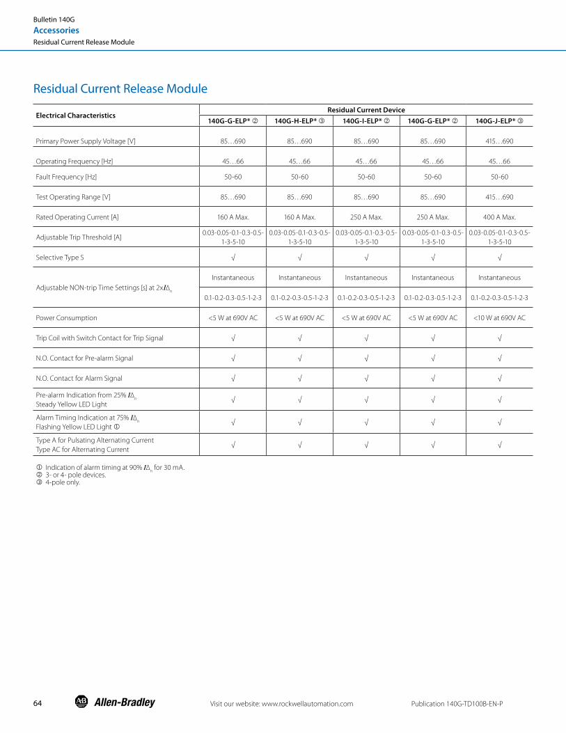
64
Residual Current Release Module
Electrical CharacteristicsResidual Current Device
140G-G-ELP* k 140G-H-ELP* l 140G-I-ELP* k 140G-G-ELP* k 140G-J-ELP* l
Primary Power Supply Voltage [V] 85…690 85…690 85…690 85…690 415…690
Operating Frequency [Hz] 45…66 45…66 45…66 45…66 45…66
Fault Frequency [Hz] 50-60 50-60 50-60 50-60 50-60
Test Operating Range [V] 85…690 85…690 85…690 85…690 415…690
Rated Operating Current [A] 160 A Max. 160 A Max. 250 A Max. 250 A Max. 400 A Max.
Adjustable Trip Threshold [A]0.03-0.05-0.1-0.3-0.5-
1-3-5-100.03-0.05-0.1-0.3-0.5-
1-3-5-100.03-0.05-0.1-0.3-0.5-
1-3-5-100.03-0.05-0.1-0.3-0.5-
1-3-5-100.03-0.05-0.1-0.3-0.5-
1-3-5-10
Selective Type S √ √ √ √ √
Adjustable NON-trip Time Settings [s] at 2xI∆n
Instantaneous Instantaneous Instantaneous Instantaneous Instantaneous
0.1-0.2-0.3-0.5-1-2-3 0.1-0.2-0.3-0.5-1-2-3 0.1-0.2-0.3-0.5-1-2-3 0.1-0.2-0.3-0.5-1-2-3 0.1-0.2-0.3-0.5-1-2-3
Power Consumption <5 W at 690V AC <5 W at 690V AC <5 W at 690V AC <5 W at 690V AC <10 W at 690V AC
Trip Coil with Switch Contact for Trip Signal √ √ √ √ √
N.O. Contact for Pre-alarm Signal √ √ √ √ √
N.O. Contact for Alarm Signal √ √ √ √ √
Pre-alarm Indication from 25% I∆n
Steady Yellow LED Light √ √ √ √ √
Alarm Timing Indication at 75% I∆n
Flashing Yellow LED Light j√ √ √ √ √
Type A for Pulsating Alternating Current Type AC for Alternating Current
√ √ √ √ √
j Indication of alarm timing at 90% I∆n for 30 mA.
k 3- or 4- pole devices. l 4-pole only.
Visit our website: www.rockwellautomation.com Publication 140G-TD100B-EN-P
Bulletin 140G
AccessoriesResidual Current Release Module

65Publication 140G-TD100B-EN-P Visit our website: www.rockwellautomation.com
Bulletin 140G
Time-Current Curves
Time-Current Curves
Motor Circuit Protectors Bulletin 140MG-G ........................................................................................................................................................ 66 Bulletin 140MG-H .........................................................................................................................................................67 Bulletin 140MG-I ...........................................................................................................................................................69 Bulletin 140MG-J ...........................................................................................................................................................70 Bulletin 140MG-K ..........................................................................................................................................................71 Bulletin 140MG-M ........................................................................................................................................................72 Bulletin 140MG-N .........................................................................................................................................................73 Bulletin 140MG-H8E....................................................................................................................................................74 Bulletin 140MG-J8E ......................................................................................................................................................75
Thermal Magnetic Molded Case Circuit Protectors Bulletin 140G-G .............................................................................................................................................................76 Bulletin 140G-H .............................................................................................................................................................82 Bulletin 140G-I ................................................................................................................................................................89 Bulletin 140G-J ...............................................................................................................................................................92 Bulletin 140G-K ..............................................................................................................................................................98 Bulletin 140G-M ........................................................................................................................................................... 99
Electronic Molded Case Circuit Protectors Bulletin 140G-H .......................................................................................................................................................... 102 Bulletin 140G-J ............................................................................................................................................................104 Bulletin 140G-K ...........................................................................................................................................................106 Bulletin 140G-M .........................................................................................................................................................108 Bulletin 140G-N, -NS .................................................................................................................................................110 Bulletin 140G-R ............................................................................................................................................................114
Let-Through Energy Curves I2t @ 240V ........................................................................................................................................................................116 I2t @ 415V.........................................................................................................................................................................117 I2t @ 480V ........................................................................................................................................................................118 I2t @ 600V ........................................................................................................................................................................119 I2t @ 690V ....................................................................................................................................................................... 120
Peak Let-Through Current Curves Peak, kA @ 240V ..........................................................................................................................................................121 Peak, kA @ 415V .......................................................................................................................................................... 122 Peak, kA @ 480V ......................................................................................................................................................... 123 Peak, kA @ 600V ..........................................................................................................................................................124 Peak, kA @ 690V ......................................................................................................................................................... 125

66
Catalog Number A B C D E F G H I140MG-G8P-B30 12 15 17 20 23 25 28 30 33140MG-G8P-B70 28 34 40 46 53 59 65 71 77140MG-G8P-C15 45 60 75 90 105 120 135 150 165140MG-G8P-C30 90 120 150 180 210 240 270 300 330140MG-G8P-C50 150 200 250 300 350 400 450 500 550140MG-G8P-C70 210 280 350 420 490 560 630 700 770140MG-G8P-C80 240 320 400 480 560 640 720 800 880140MG-G8P-D10 300 400 500 600 700 800 900 1000 1100140MG-G8P-D12 375 500 625 750 875 1000 1125 1250 1375
I3 [A]A B C D E F G H I
300 400 500 600 700 800 900 1000 1100
Instantaneous Pick-up Setting (Amperes)
Typical Trip Unit Nameplate
See chart on left for trip setting values.
Note: Motor circuit protectors are for use only in combination controllers. For DC applications, pick-up settings are approximately 40% higher.
Visit our website: www.rockwellautomation.com Publication 140G-TD100B-EN-P
Bulletin 140MG-G
Maximum Current: 3…125 A
Bulletin 140MG
Time-Current CurvesMotor Circuit Protectors

67
Catalog Number A B C D E F G H I140MG-H8P-B30 12 15 17 20 23 25 28 30 33140MG-H8P-B70 28 34 40 46 53 59 65 71 77140MG-H8P-C15 45 60 75 90 105 120 135 150 165140MG-H8P-C30 90 120 150 180 210 240 270 300 330140MG-H8P-C50 150 200 250 300 350 400 450 500 550140MG-H8P-C70 210 280 350 420 490 560 630 700 770140MG-H8P-C80 240 320 400 480 560 640 720 800 880140MG-H8P-D10 300 400 500 600 700 800 900 1000 1100
I3 [A]A B C D E F G H I
300 400 500 600 700 800 900 1000 1100
Instantaneous Pick-up Setting (Amperes)
Typical Trip Unit Nameplate
See chart on left for trip setting values.
Note: Motor circuit protectors are for use only in combination controllers. For DC applications, pick-up settings are approximately 40% higher.
Publication 140G-TD100B-EN-P Visit our website: www.rockwellautomation.com
Bulletin 140MG-H
Maximum Current: 3…100 A
Bulletin 140MG
Time-Current CurvesMotor Circuit Protectors
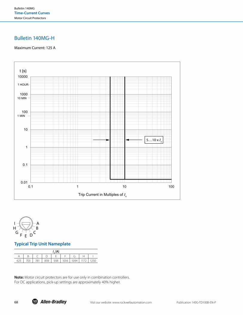
68 Visit our website: www.rockwellautomation.com Publication 140G-TD100B-EN-P
Bulletin 140MG-H
Maximum Current: 125 A
Bulletin 140MG
Time-Current CurvesMotor Circuit Protectors
I3 [A]A B C D E F G H I
625 703 781 859 938 1016 1094 1172 1250
Typical Trip Unit Nameplate
Note: Motor circuit protectors are for use only in combination controllers. For DC applications, pick-up settings are approximately 40% higher.

69Publication 140G-TD100B-EN-P Visit our website: www.rockwellautomation.com
Bulletin 140MG
Time-Current CurvesMotor Circuit Protectors
Catalog Number A B C D E F G H I140MG-I8P-D10 600 675 750 825 900 975 1050 1125 1200140MG-I8P-D11 660 743 825 908 990 1073 1155 1238 1320140MG-I8P-D12 750 844 938 1031 1125 1219 1313 1406 1500140MG-I8P-D15 900 1013 1125 1238 1350 1463 1575 1688 1800
I3 [A]A B C D E F G H I
600 675 750 825 900 975 1050 1125 1200
Instantaneous Pick-up Setting (Amperes)
Typical Trip Unit Nameplate
See chart on left for trip setting values.
Note: Motor circuit protectors are for use only in combination controllers. For DC applications, pick-up settings are approximately 40% higher.
Bulletin 140MG-I
Maximum Current: 100…150 A

70 Visit our website: www.rockwellautomation.com Publication 140G-TD100B-EN-P
Catalog Number A B C D E F G H I140MG-J8P-D15 750 844 938 1031 1125 1219 1313 1406 1500140MG-J8P-D17 875 984 1094 1203 1313 1422 1531 1641 1750140MG-J8P-D20 1000 1125 1250 1375 1500 1625 1750 1875 2000140MG-J8P-D22 1125 1266 1406 1547 1688 1828 1969 2109 2250140MG-J8P-D25 1250 1406 1563 1719 1875 2031 2188 2344 2500
I3 [A]A B C D E F G H I
750 844 938 1031 1125 1219 1313 1406 1500
Instantaneous Pick-up Setting (Amperes)
Typical Trip Unit Nameplate
See chart on left for trip setting values.
Note: Motor circuit protectors are for use only in combination controllers. For DC applications, pick-up settings are approximately 40% higher.
Bulletin 140MG-J
Maximum Current: 150…250 A
Bulletin 140MG
Time-Current CurvesMotor Circuit Protectors

71Publication 140G-TD100B-EN-P Visit our website: www.rockwellautomation.com
Bulletin 140MG
Time-Current CurvesMotor Circuit Protectors
Bulletin 140MG-K
Maximum Current: 300 A, 400 A
Note: Motor circuit protectors are for use only in combination controllers. For DC applications, pick-up settings are approximately 40% higher.

72 Visit our website: www.rockwellautomation.com Publication 140G-TD100B-EN-P
Bulletin 140MG-M
Maximum Current: 600 A, 800 A
Bulletin 140MG
Time-Current CurvesMotor Circuit Protectors
Note: Motor circuit protectors are for use only in combination controllers. For high fault current levels an additional fixed instantaneous override is provided at 9.6 kA.

73Publication 140G-TD100B-EN-P Visit our website: www.rockwellautomation.com
Bulletin 140MG-N
Maximum Current: 1200 A
Bulletin 140MG
Time-Current CurvesMotor Circuit Protectors
Note: Motor circuit protectors are for use only in combination controllers. For high fault current levels an additional fixed instantaneous override is provided at 22 kA.

74 Visit our website: www.rockwellautomation.com Publication 140G-TD100B-EN-P
Bulletin 140MG
Time-Current CurvesMotor Circuit Protectors
Bulletin 140MG-H8E
Available Current Sensors: 25 A, 60 A, 100 A
Note: Set L function value equal motor FLA.

75Publication 140G-TD100B-EN-P Visit our website: www.rockwellautomation.com
Bulletin 140MG
Time-Current CurvesMotor Circuit Protectors
Bulletin 140MG-J8E
Available Current Sensors: 40 A, 60 A, 100 A, 150 A
Note: Set L function value equal motor FLA.

76 Visit our website: www.rockwellautomation.com Publication 140G-TD100B-EN-P
Bulletin 140G-G
Maximum Current: 15…30 A
Bulletin 140G
Time-Current CurvesThermal Magnetic Molded Case Circuit Breakers
Rated Current In [A]
Magnetic Trip Im [A]
15…30 500

77Publication 140G-TD100B-EN-P Visit our website: www.rockwellautomation.com
Bulletin 140G
Time-Current CurvesThermal Magnetic Molded Case Circuit Breakers
Bulletin 140G-G
Maximum Current: 32 A

78 Visit our website: www.rockwellautomation.com Publication 140G-TD100B-EN-P
Bulletin 140G
Time-Current CurvesThermal Magnetic Molded Case Circuit Breakers
Bulletin 140G-G
Maximum Current: 35…50 A
Rated Current In [A]
Magnetic Trip Im [A]
35…50 500

79Publication 140G-TD100B-EN-P Visit our website: www.rockwellautomation.com
Bulletin 140G
Time-Current CurvesThermal Magnetic Molded Case Circuit Breakers
Bulletin 140G-G
Maximum Current: 60…100 A
Rated Current In [A]
Magnetic Trip Im [A]
60 600
63 630
70 700
80 800
90 900
100 1000

Bulletin 140G-G
Maximum Current: 125 A
80 Visit our website: www.rockwellautomation.com Publication 140G-TD100B-EN-P
Bulletin 140G
Time-Current CurvesThermal Magnetic Molded Case Circuit Breakers

81Publication 140G-TD100B-EN-P Visit our website: www.rockwellautomation.com
Bulletin 140G-G
Maximum Current: 160 A
Bulletin 140G
Time-Current CurvesThermal Magnetic Molded Case Circuit Breakers

82 Visit our website: www.rockwellautomation.com Publication 140G-TD100B-EN-P
Bulletin 140G-H
Maximum Current: 15…30 A
Bulletin 140G
Time-Current CurvesThermal Magnetic Molded Case Circuit Breakers
Rated Current In [A]
Magnetic Trip Im [A]
15…30 400

83Publication 140G-TD100B-EN-P Visit our website: www.rockwellautomation.com
Bulletin 140G-H
Maximum Current: 32 A
Bulletin 140G
Time-Current CurvesThermal Magnetic Molded Case Circuit Breakers

84 Visit our website: www.rockwellautomation.com Publication 140G-TD100B-EN-P
Bulletin 140G
Time-Current CurvesThermal Magnetic Molded Case Circuit Breakers
Bulletin 140G-H
Maximum Current: 35…50 A
Rated Current In [A]
Magnetic Trip Im [A]
35 400
40 400
50 500

85Publication 140G-TD100B-EN-P Visit our website: www.rockwellautomation.com
Bulletin 140G
Time-Current CurvesThermal Magnetic Molded Case Circuit Breakers
Bulletin 140G-H
Maximum Current: 60…70 A
Rated Current In [A]
Magnetic Trip Im [A]
60 600
63 630
70 700

Bulletin 140G-H
Maximum Current: 80…100 A
86 Visit our website: www.rockwellautomation.com Publication 140G-TD100B-EN-P
Bulletin 140G
Time-Current CurvesThermal Magnetic Molded Case Circuit Breakers

87Publication 140G-TD100B-EN-P Visit our website: www.rockwellautomation.com
Bulletin 140G
Time-Current CurvesThermal Magnetic Molded Case Circuit Breakers
Bulletin 140G-H
Maximum Current: 110…125 A

88 Visit our website: www.rockwellautomation.com Publication 140G-TD100B-EN-P
Bulletin 140G
Time-Current CurvesThermal Magnetic Molded Case Circuit Breakers
Bulletin 140G-H
Maximum Current: 160 A

89Publication 140G-TD100B-EN-P Visit our website: www.rockwellautomation.com
Bulletin 140G-I
Maximum Current: 60…100 A
Bulletin 140G
Time-Current CurvesThermal Magnetic Molded Case Circuit Breakers

90 Visit our website: www.rockwellautomation.com Publication 140G-TD100B-EN-P
Bulletin 140G-I
Maximum Current: 100…150 A
Bulletin 140G
Time-Current CurvesThermal Magnetic Molded Case Circuit Breakers

91Publication 140G-TD100B-EN-P Visit our website: www.rockwellautomation.com
Bulletin 140G-I
Maximum Current: 160…225 A
Bulletin 140G
Time-Current CurvesThermal Magnetic Molded Case Circuit Breakers

92 Visit our website: www.rockwellautomation.com Publication 140G-TD100B-EN-P
Bulletin 140G-J
Maximum Current: 25…50 A
Bulletin 140G
Time-Current CurvesThermal Magnetic Molded Case Circuit Breakers
Rated Current In [A]
Magnetic Trip Im [A]
25…40 400
50 500

93Publication 140G-TD100B-EN-P Visit our website: www.rockwellautomation.com
Bulletin 140G-J
Maximum Current: 60…70 A
Bulletin 140G
Time-Current CurvesThermal Magnetic Molded Case Circuit Breakers
Rated Current In [A]
Magnetic Trip Im [A]
60 600
63 630
70 700

94 Visit our website: www.rockwellautomation.com Publication 140G-TD100B-EN-P
Bulletin 140G-J
Maximum Current: 80…100 A
1 HOUR
10 MIN
1 MIN
0.01
0.1
1
10
100
1000
10000
0.1 1 10 100
t [s]
Current in Multiples of In
Bulletin 140G
Time-Current CurvesThermal Magnetic Molded Case Circuit Breakers

95Publication 140G-TD100B-EN-P Visit our website: www.rockwellautomation.com
Bulletin 140G-J
Maximum Current: 110…150 A
Bulletin 140G
Time-Current CurvesThermal Magnetic Molded Case Circuit Breakers

96 Visit our website: www.rockwellautomation.com Publication 140G-TD100B-EN-P
Bulletin 140G-J
Maximum Current: 160…225 A
Bulletin 140G
Time-Current CurvesThermal Magnetic Molded Case Circuit Breakers

97Publication 140G-TD100B-EN-P Visit our website: www.rockwellautomation.com
Bulletin 140G-J
Maximum Current: 250 A
Bulletin 140G
Time-Current CurvesThermal Magnetic Molded Case Circuit Breakers

98 Visit our website: www.rockwellautomation.com Publication 140G-TD100B-EN-P
Bulletin 140G-K
Maximum Current: 300 A, 400 A
Bulletin 140G
Time-Current CurvesThermal Magnetic Molded Case Circuit Breakers

99Publication 140G-TD100B-EN-P Visit our website: www.rockwellautomation.com
Bulletin 140G-M
Maximum Current: 600 A
Bulletin 140G
Time-Current CurvesThermal Magnetic Molded Case Circuit Breakers

100 Visit our website: www.rockwellautomation.com Publication 140G-TD100B-EN-P
Bulletin 140G-M
Maximum Current: 800 A
Bulletin 140G
Time-Current CurvesThermal Magnetic Molded Case Circuit Breakers

101Publication 140G-TD100B-EN-P Visit our website: www.rockwellautomation.com
Bulletin 140G
Time-Current CurvesThermal Magnetic Molded Case Circuit Breakers
Page Left Blank Intentionally

102 Visit our website: www.rockwellautomation.com Publication 140G-TD100B-EN-P
Bulletin 140G-H
Available Sensors (In): 25 A, 60 A, 100 A, 125 A
Electronic Trip Unit. Long Delay Response, Short Delay with I 2t Response, and Instantaneous Curve
Notes:
1. Curve accuracy applies from -20 ˚C to +55 ˚C (-4 ˚F to +131 ˚F) ambient temperature. For possible continuous ampere derating for ambient temperature above 40 ˚C (104 ˚F), consult your local Rockwell Automation sales office or Allen-Bradley distributor.
2. The right portion of the curve is determined by the interrupting rating of the circuit breaker.
3. Total clearing times shown include the response times of the trip unit, the breaker opening, and the interruption of the current.
4. For high fault current levels an additional fixed instantaneous hardware override is provided at 2.2 kA.
Protection Trip Threshold Trip Time
L 1.05 ≤ xI1 ≤ 1.25 ± 20%
S ± 10% ± 20%I ± 15% ≤ 60 ms
Others ± 20%
Tolerance Values
Bulletin 140G
Time-Current CurvesElectronic Molded Case Circuit Breakers

103Publication 140G-TD100B-EN-P Visit our website: www.rockwellautomation.com
Bulletin 140G-H
Ground Fault Protection Curve
I4 [I
n]
In [A] 0.2 0.25 0.45 0.55 0.75 0.8 1
140G-H
25 5 6.25 11.3 13.8 18.8 20 2560 12 15 27 33 45 48 60
100 20 25 45 55 75 80 100125 25 31.3 56.3 68.8 93.8 100 125160* 32 40 72 88 120 128 160
For L-S-I trip curve see Pub. 140G-TD021.
Bulletin 140G
Time-Current CurvesElectronic Molded Case Circuit Breakers
Protection Trip Threshold Trip TimeG ± 10% ± 20%
Tolerance Values

104 Visit our website: www.rockwellautomation.com Publication 140G-TD100B-EN-P
Bulletin 140G-J
Available Sensors (In): 40 A, 60 A, 100 A, 150 A, 250 A
Electronic Trip Unit. Long Delay Response, Short Delay with I 2t Response, and Instantaneous Curve
Notes:
1. Curve accuracy applies from -20 ˚C to +55 ˚C (-4 ˚F to +131 ˚F) ambient temperature. For possible continuous ampere derating for ambient temperature above 40 ˚C (104 ˚F), consult your local Rockwell Automation sales office or Allen-Bradley distributor.
2. The right portion of the curve is determined by the interrupting rating of the circuit breaker.
3. Total clearing times shown include the response times of the trip unit, the breaker opening, and the interruption of the current.
4. For high fault current levels an additional fixed instantaneous hardware override is provided at 3 kA.
Protection Trip Threshold Trip Time
L 1.05 ≤ xI1 ≤ 1.25 ± 20%
S ± 10% ± 20%I ± 15% ≤ 60 ms
Others ± 20%
Tolerance Values
Bulletin 140G
Time-Current CurvesElectronic Molded Case Circuit Breakers

105Publication 140G-TD100B-EN-P Visit our website: www.rockwellautomation.com
Bulletin 140G-J
Ground Fault Protection Curve for LSIG MCCBS
I4 [I
n]
In [A] 0.2 0.25 0.45 0.55 0.75 0.8 1
140G-J
40 8 10 18 22 30 32 4060 12 15 27 33 45 48 60
100 20 25 45 55 75 80 100150 30 37.5 67.5 82.5 113 120 150250 50 62.5 113 138 188 200 250
For L-S-I trip curve see Pub. 140G-TD023.
Example:
In = 100 A
I4 = 100 x (0.2 + 0.25) = 45 A
t4 = 0.2 s @ I > I4
Bulletin 140G
Time-Current CurvesElectronic Molded Case Circuit Breakers
Protection Trip Threshold Trip TimeG ± 10% ± 20%
Tolerance Values

106 Visit our website: www.rockwellautomation.com Publication 140G-TD100B-EN-P
Bulletin 140G-K
Available Sensors (In): 300 A, 400 A
Electronic Trip Unit. Long Delay Response, Short Delay with I 2t Response, and Instantaneous Curve
Notes:
1. Curve accuracy applies from -20 ˚C to +55 ˚C (-4 ˚F to +131 ˚F) ambient temperature. For possible continuous ampere derating for ambient temperature above 40 ˚C (104 ˚F), consult your local Rockwell Automation sales office or Allen-Bradley distributor.
2. The right portion of the curve is determined by the interrupting rating of the circuit breaker.
3. Total clearing times shown include the response times of the trip unit, the breaker opening, and the interruption of the current.
4. For high fault current levels an additional fixed instantaneous hardware override is provided at 5 kA.
Protection Trip Threshold Trip Time
L 1.05 ≤ xI1 ≤ 1.25 ± 20%
S ± 10% ± 20%I ±1 5% ≤ 60 ms
Others ± 20%
Tolerance Values
I3 [I
n]
In [A] 1.5 2.5 3 4 4.5 5 5.5 6.5 7 7.5 8 9 9.5 10.5 12
300 450 750 900 1200 1350 1500 1650 1950 2100 2250 2400 2700 2850 3150 3600400 600 1000 1200 1600 1800 2000 2200 2600 2800 3000 3200 3600 3800 4200 4800
Example:
In = 300 A
I3 = 300 x (1.5 + 3) = 1350 A
Bulletin 140G
Time-Current CurvesElectronic Molded Case Circuit Breakers

107Publication 140G-TD100B-EN-P Visit our website: www.rockwellautomation.com
Bulletin 140G-K
Ground Fault Protection Curve for LSIG MCCBS
I4 [I
n]
In [A] 0.2 0.25 0.45 0.55 0.75 0.8 1
300 60 75 135 165 225 240 300400 80 100 180 220 300 320 400
For L-S-I trip curve see Pub. 140G-TD025.
Example:
In = 100 A
I4 = 100 x (0.2 + 0.25) = 45 A
t4 = 0.2 s
Bulletin 140G
Time-Current CurvesElectronic Molded Case Circuit Breakers
Protection Trip Threshold Trip TimeG ± 10% ± 20%
Tolerance Values

108 Visit our website: www.rockwellautomation.com Publication 140G-TD100B-EN-P
Bulletin 140G-M
Available Sensors (In): 600 A, 800 A
Electronic Trip Unit. Long Delay Response, Short Delay with I 2t Response, and Instantaneous Curve
Protection Trip Threshold Trip Time
L 1.05 ≤ xI1 ≤ 1.25 ± 20%
S ± 10% ± 20%I ± 15% ≤ 60 ms
Others ± 20%
Tolerance Values
Example:
In = 600 A
I3 = 600 x (1.5 + 3) = 2700 A
Notes:
1. Curve accuracy applies from -20 ˚C to +55 ˚C (-4 ˚F to +131 ˚F) ambient temperature. For possible continuous ampere derating for ambient temperature above 40 ˚C (104 ˚F), consult your local Rockwell Automation sales office or Allen-Bradley distributor.
2. The right portion of the curve is determined by the interrupting rating of the circuit breaker.
3. Total clearing times shown include the response times of the trip unit, the breaker opening, and the interruption of the current.
4. For high fault current levels an additional fixed instantaneous hardware override is provided at 9.6 kA.
Bulletin 140G
Time-Current CurvesElectronic Molded Case Circuit Breakers

109Publication 140G-TD100B-EN-P Visit our website: www.rockwellautomation.com
Bulletin 140G
Time-Current CurvesElectronic Molded Case Circuit Breakers
Bulletin 140G-M
Available Sensors (In): 600 A, 800 A
For L-S-I trip curve see Pub. 140G-TD028.
Example:
In = 600 A
I4 = 600 x (0.2 + 0.25) = 270 A
t4 = 0.2 s
Ground Fault Protection Curve for LSIG MCCBS
Protection Trip Threshold Trip TimeG ± 10% ± 20%
Tolerance Values

110 Visit our website: www.rockwellautomation.com Publication 140G-TD100B-EN-P
Bulletin 140G-N, -NS
Available Rating Plugs (In): 400 A, 800 A, 1000 A, 1200 A, 1250 A (IEC)
LSI
Notes:1. The minimum value of this trip is 1 s regardless of curve type (self-protection)
2. These tolerances apply under the following conditions: - self-powered relay at full power (without start-up) - presence of auxiliary power supply - two-phase or three-phase power supply - preset trip time ≥ 100 ms
3. Curve accuracy applies from -20 ˚C to +55 ˚C ambient. For possible continuous ampere derating for ambient above 40 ˚C, consult Rockwell Automation.
4. The right portion of the curve is determined by the interrupting rating of the circuit breaker.
5. Total clearing times shown include the response times of the trip unit, the breaker opening, and the interruption of the current.
6. For high fault current levels an additional fixed instantaneous hardware override is provided at 22 kA.
Protection Disable Trip Threshold Trip Time Trip Threshold Tolerance(2) Trip Time Tolerance (2)
L (t=k/I2)
I1=0.4-0.44-0.48-0.52…1 x I
nt
1=3-6-12-18 s(1) @ 6I
1
Release between 1.05 and 1.2 x I
1
± 10% If ≤ 6 x I
n
S (t=k)
4I
2=0.6-0.8-1.2-1.8-2.4-3-3.6-4.2-5-5.8-
6.6-7.4-8.2-9-10 x In
with I > I2
t2=0.1-0.25-0.5-0.8 s
± 7% If ≤ 6 x I
n
± 10% If > 6 x I
n
The best of: ± 10% or ± 40 ms
S (t=k/I2)
4I
2=0.6-0.8-1.2-1.8-2.4-3-3.6-4.2-5-5.8-
6.6-7.4-8.2-9-10 x In
I=10 x In
t2=0.1-0.25-0.5-0.8 s
± 7% If ≤ 6 x I
n
± 10% If > 6 x I
n
± 15% If ≤ 6 x I
n
± 20% If > 6 x I
n
I (t=k)
4I
3=1.5-2.5-3-4-4.5-5-5.5-6.5-7-7.5-8-9-
9.5-10.5-12 x In
≤ 30 ms ± 10%
Protection Trip Threshold Trip Time
L 1.05 ≤ xI1 ≤ 1.25 ± 20%
S ± 10% ± 20%I ± 15% ≤ 60 ms
Others ± 20%
For all cases not covered by the above assumptions, the following tolerance values apply:
Bulletin 140G
Time-Current CurvesElectronic Molded Case Circuit Breakers

111Publication 140G-TD100B-EN-P Visit our website: www.rockwellautomation.com
Bulletin 140G
Time-Current CurvesElectronic Molded Case Circuit Breakers
Page Left Blank Intentionally

112 Visit our website: www.rockwellautomation.com Publication 140G-TD100B-EN-P
Bulletin 140G
Time-Current CurvesElectronic Molded Case Circuit Breakers
Notes:1. The minimum value of this trip is 1 s regardless of curve type (self-protection)
2. These tolerances apply under the following conditions: - self-powered relay at full power (without start-up) - presence of auxiliary power supply - two-phase or three-phase power supply - preset trip time ≥ 100 ms
3. Curve accuracy applies from -20 ˚C to +55 ˚C ambient. For possible continuous ampere derating for ambient above 40 ˚C, consult Rockwell Automation.
4. The right portion of the curve is determined by the interrupting rating of the circuit breaker.
5. Total clearing times shown include the response times of the trip unit, the breaker opening, and the interruption of the current.
6. For high fault current levels an additional fixed instantaneous hardware override is provided at 22 kA.
Protection Disable Trip Threshold Trip Time Trip Threshold Tolerance(2) Trip Time Tolerance (2)
L (t=k/I2)
I1=0.4-0.425-0.45-0.475-0.5…-1 x I
nt
1=3-12-24-36-48-72-108-144 s(1) @ 3I
1
Release between 1.05 and 1.2 x I
1
± 10% If ≤ 6 x I
n
S (t=k)
4I
2=0.6-0.8-1.2-1.8-2.4-3-3.6-4.2-5-5.8-
6.6-7.4-8.2-9-10 x In
with I > I2
t2=0.1-0.2-0.3-0.4-0.5-0.6-0.7-0.8 s
± 7% If ≤ 6 x I
n
± 10% If > 6 x I
n
The best of: ± 10% or ± 40 ms
S (t=k/I2)
4I
2=0.6-0.8-1.2-1.8-2.4-3-3.6-4.2-5-5.8-
6.6-7.4-8.2-9-10 x In
t2=0.1-0.2-0.3-0.4-0.5-0.6-0.7-0.8 s
@ 10 In
± 7% If ≤ 6 x I
n
± 10% If > 6 x I
n
± 15% If ≤ 6 x I
n
± 20% If > 6 x I
n
I (t=k)
4I
3=1.5-2-3-4-5-6-7-8-9-10-11-12-13-
14-15 x In
≤ 30 ms ± 10%
Protection Trip Threshold Trip Time
L 1.05 ≤ xI1 ≤ 1.25 ± 20%
S ± 10% ± 20%I ± 15% ≤ 60 ms
Others ± 20%
For all cases not covered by the above assumptions, the following tolerance values apply:
Bulletin 140G-N, -NS
Available Rating Plugs (In): 400 A, 800 A, 1000 A, 1200 A, 1250 A (IEC)
LSIG

113Publication 140G-TD100B-EN-P Visit our website: www.rockwellautomation.com
Bulletin 140G
Time-Current CurvesElectronic Molded Case Circuit Breakers
Bulletin 140G-N, -NS
Protection Disable Trip Threshold Trip Time Trip Threshold Tolerance Trip Time Tolerance
G (t=k)
4 I4=0.2-0.3-0.4-0.6-0.8-0.9-1 x I
n
with I > I4
t4=0.1-0.2-0.4-0.8 s
± 7%The best of: ± 10% or ± 40 ms
G (t=k/I2)
4 I4=0.2-0.3-0.4-0.6-0.8-0.9-1 x I
n
t4=0.1 @ 4.47 I
4
t4=0.2 @ 3.16 I
4
t4=0.4 @ 2.24 I
4
t4=0.8 @ 1.58 I
4
± 7% ± 15%
Ground Fault Protection Curve for LSIG MCCB
Protection Trip Threshold Trip TimeG ± 10% ± 20%
Others ± 20%
For all cases not covered by the above assumptions, the following tolerance values apply:
For L-S-I trip curve see Pub. 140G-TD031.

114 Visit our website: www.rockwellautomation.com Publication 140G-TD100B-EN-P
Bulletin 140G
Time-Current CurvesElectronic Molded Case Circuit Breakers
Bulletin 140G-R
Available Sensors (In): 2000 A, 2500 A, 3000 A
Electronic Trip Unit. Long Delay Response, Short Delay with I 2t Response, and Instantaneous Curve
Notes:1. The minimum value of this trip is 1s regardless of curve type (self-protection)
2. These tolerances apply under the following conditions: - self-powered relay at full power (without start-up) - presence of auxiliary power supply - two-phase or three-phase power supply - preset trip time ≥ 100 ms
3. Curve accuracy applies from -20 ˚C to +55 ˚C (-4 ˚F to +131 ˚F) ambient temperature. For possible continuous ampere derating for ambient temperature above 40 ˚C (104 ˚F), consult your local Rockwell Automation sales office or Allen-Bradley distributor.
4. The right portion of the curve is determined by the interrupting rating of the circuit breaker.
5. Total clearing times shown include the response times of the trip unit, the breaker opening, and the interruption of the current.
6. For high fault current levels an additional fixed instantaneous hardware override is provided at 40 kA.
Protection Disable Trip Threshold Trip Time Trip Threshold Tolerance (2) Trip Time Tolerance (2)
L (t=k/I2)
I1=0.4-0.425-0.45-0.475-0.5…-1 x I
nt
1=3-12-24-36-48-72-108-144 s(1) @ 3I
1
Release between 1.05 and 1.2 x I
1
± 10% If ≤ 6 x I
n
S (t=k)
4I
2=0.6-0.8-1.2-1.8-2.4-3-3.6-4.2-5-5.8-
6.6-7.4-8.2-9-10 x In
with I > I2
t2=0.1-0.2-0.3-0.4-0.5-0.6-0.7-0.8 s
± 7% If ≤ 6 x I
n
± 10% If > 6 x I
n
The best of: ± 10% or ± 40 ms
S (t=k/I2)
4I
2=0.6-0.8-1.2-1.8-2.4-3-3.6-4.2-5-5.8-
6.6-7.4-8.2-9-10 x In
t2=0.1-0.2-0.3-0.4-0.5-0.6-0.7-0.8 s
@ 10 In
± 7% If ≤ 6 x I
n
± 10% If > 6 x I
n
± 15% If ≤ 6 x I
n
± 20% If > 6 x I
n
I (t=k)
4I
3=1.5-2-3-4-5-6-7-8-9-10-11-12-13-
14-15 x In
≤ 30 ms ± 10%
G (t=k)
4 I4=0.2-0.3-0.4-0.6-0.8-0.9-1 x I
n
with I > I4
t4=0.1-0.2-0.4-0.8 s
± 7%The best of: ± 10% or ± 40 ms
G (t=k/I2)
4 I4=0.2-0.3-0.4-0.6-0.8-0.9-1 x I
n
t4=0.1 @ 4.47 I
4 t
4=0.2 @ 3.16 I
4
t4=0.4 @ 2.24 I
4 t
4=0.8 @ 1.58 I
4
± 7% ± 15%
Protection Trip Threshold Trip Time
L 1.05 ≤ x I1 ≤ 1.25 ± 20%
S ± 10% ± 20%I ± 15% ≤ 60 msG ± 10% ± 20%
Others ± 20%
For all cases not covered by the above assumptions, the following tolerance values apply:

115Publication 140G-TD100B-EN-P Visit our website: www.rockwellautomation.com
Bulletin 140G
Time-Current CurvesElectronic Molded Case Circuit Breakers
Page Left Blank Intentionally

116 Visit our website: www.rockwellautomation.com Publication 140G-TD100B-EN-P
Bulletin 140G
Let-Through Energy Curves I 2t
Bulletin 140G
I2t Let-Through Energy Curve @ 240V
Available Short Circuit Current, kA rms
I2 t (A
2 s)
1,000,000,000
100,000,000
10,000,000
1,000,000
100,000 1 10 100 1000
N
M
H
J
K
G

117Publication 140G-TD100B-EN-P Visit our website: www.rockwellautomation.com
Bulletin 140G
I2t Let-Through Energy Curve @ 415V
Available Short Circuit Current, kA rms
I2 t (A
2 s)
1,000,000,000
100,000,000
10,000,000
1,000,000
100,000
10,000 1 10 100 1000
R
N
M
J
I
H
G
K
Bulletin 140G
Let-Through Energy Curves I 2t

118 Visit our website: www.rockwellautomation.com Publication 140G-TD100B-EN-P
Bulletin 140G
Let-Through Energy Curves I 2t
Bulletin 140G
I2t Let-Through Energy Curve @ 480V
Available Short Circuit Current, kA rms
I2 t (A
2 s)
1,000,000,000
100,000,000
10,000,000
1,000,000
100,000 1 10 100 1000
N
M
R
H
J
K
G

119Publication 140G-TD100B-EN-P Visit our website: www.rockwellautomation.com
Bulletin 140G
Let-Through Energy Curves I 2t
Bulletin 140G
I2t Let-Through Energy Curve @ 600V
Available Short Circuit Current, kA rms
I2 t (A
2 s)
1,000,000,000
100,000,000
10,000,000
1,000,000
100,000 1 10 100 1000
N
M
R
H
J
K
G

120 Visit our website: www.rockwellautomation.com Publication 140G-TD100B-EN-P
Bulletin 140G
Let-Through Energy Curves I 2t
Bulletin 140G
I2t Let-Through Energy Curve @ 690V
I
Available Short Circuit Current, kA rms
I2 t (A
2 s)
1,000,000,000
100,000,000
10,000,000
1,000,000
100,000
10,000 1 10 100
H
M
K
J
N
G
R

121Publication 140G-TD100B-EN-P Visit our website: www.rockwellautomation.com
Bulletin 140G
Peak Let-Through Current Curves
Bulletin 140G
Peak Let-Through Current, kA @ 240V
I p [kA
]
Available Short Circuit Current, kA rms
1 kA
10 kA
100 kA
1000 kA
1 10 100 1000
NM
H
J
K
G

122 Visit our website: www.rockwellautomation.com Publication 140G-TD100B-EN-P
Bulletin 140G
Peak Let-Through Current, kA @ 415V
Ip [k
A]
Available Short Circuit Current, kA rms
1 kA
10 kA
100 kA
1000 kA
1 10 100 1000
G
KJ
R
N
M
HI
Bulletin 140G
Peak Let-Through Current Curves

123Publication 140G-TD100B-EN-P Visit our website: www.rockwellautomation.com
Bulletin 140G
Peak Let-Through Current Curves
Bulletin 140G
Peak Let-Through Current, kA @ 480V
Ip [k
A]
Available Short Circuit Current, kA rms
1 kA
10 kA
100 kA
1000 kA
1 10 100 1000
N
M
R
H
JK
G

124 Visit our website: www.rockwellautomation.com Publication 140G-TD100B-EN-P
Bulletin 140G
Peak Let-Through Current Curves
Bulletin 140G
Peak Let-Through Current, kA @ 600V
Ip [k
A]
Available Short Circuit Current, kA rms
1 kA
10 kA
100 kA
1000 kA
1 10 100 1000
N
M
R
HJ
K
G

125Publication 140G-TD100B-EN-P Visit our website: www.rockwellautomation.com
Bulletin 140G
Peak Let-Through Current Curves
Bulletin 140G
Peak Let-Through Current, kA @ 690V
Ip [k
A]
Available Short Circuit Current, kA rms
1 kA
10 kA
100 kA
1000 kA
1 10 100
R
N
MK
IJ
GH


Local DistributorVisit our website to find your local Distributor.
www.rockwellautomation.com/distributor
On-Line Product DirectoryOur extensive product portfolio is designed to improve your processes through every stage of your manufacturing cycle.
http://ab.rockwellautomation.com/Circuit-and-Load-Protection/Circuit-Breakers
Product Selection ToolboxOur powerful range of product selection and system configuration tools assist you in choosing and applying our products.
www.rockwellautomation.com/en/e-tools
CAD drawings in a range of formats
Selection guides and technical documentation
Bulletin 140GMolded Case Circuit Breakers
49
Visit our website: www.ab.com/catalogsPublication 140G-SG001A-EN-P
AccessoriesDiagrams
32
34
34
AX3
32
31
31
21
21
22
22
AX2
24
24
24
24
AX2
22
22
21
21
D
H96
98
98
95
95
AL1
96 16
AL2
15
15
18
18
16
16
18
18
15
15
AL2
16
24
AX2
11
11
14
AX1
1412
12
22
22
21
21
31
31
32
AX3
32
24
9634
34
AL1
95
95
98
98
96
G
0805
TU AL
06
06
05
08
96
98
98
95
95
AL1
96
11
24
AX2
11
14
AX1
1412
12
22
22
21
21
31
31
32
AX3
32
24
9634
34
AL1
95
95
98
98
96
F
06
9624
AX2
11
11
14
AX1
1412
12
22
22
21
21
24
AL1
95
95
98
98
96
E
08
05
06
TU AL
0508
C24
24
AX2
22
22
21
21
96
98
98
95
95
AL1
96
AB
J
L
24
AX2
11
11
14
AX1
1412
12
22
22
21
21
31
31
32
AX3
32
24
34
34
41
41
4442
K
AX4
42 44
TU AL
Bulletin 140G
Molded Case Circuit Breakers
69
Visit our website: www.ab.com/catalogs
Publication 140G-SG001A-EN-P
Approximate Dimensions — 125 A, G-Frame
Cat. No. 140G-G-RMB or 140G-G-RMY Direct Rotary Operating Handle
Drilling: See Detail “A”
Min. door rotation radius
‡ Rotary handle operating mechanism on molded case circuit breaker
♣ Door drilling template with direct rotary handle
♦ Required 25 mm insulating phase barriers provided
Cat. Nos. 140G-G-TLC13, 140G-G-TLC14 Terminals (Copper Only Lug)
‡ Front terminals
Cat. No. 140G-G-MTL63, -MTL64 Terminal (Multi-Cable Terminal Lug)
♣ Required terminal covers with IP40 protection provided
∆ Terminal lugs for multi-cable connection
Selection and Application ToolsCircuit breakers from Rockwell Automation provide a range of tools to help you understand and apply these products in your application. You can access these tools online or through your local distributor.
Publication 140G-TD100B-EN-P – May 2015 Copyright © 2015 Rockwell Automation, Inc. All Rights Reserved. Printed in USA.Supersedes Publication 140G-TD100A-EN-P – April 2014
Allen-Bradley, LISTEN. THINK. SOLVE. and Rockwell Software are trademarks of Rockwell Automation, Inc. Trademarks not belonging to Rockwell Automation are property of their respective companies.
Rockwell Automation, Inc. (NYSE:ROK), the world’s largest company dedicated to industrial automation, makes its customers more productive and the world more sustainable. Throughout the world, our flagship Allen-Bradley® and Rockwell Software® product brands are recognized for innovation and excellence.


