19
Molecular Dynamics Simulation Solid-Liquid Phase Diagram of Argon ZCE 111 Computational Physics Semester Project by Gan Sik Hong (105513) Hwang Hsien Shiung (105762)
| Date post: | 30-Dec-2015 |
| Category: |
Documents |
| Upload: | owen-horton |
| View: | 213 times |
| Download: | 0 times |
Molecular Dynamics SimulationSolid-Liquid Phase Diagram of Argon
ZCE 111Computational Physics
Semester Project
byGan Sik Hong (105513)
Hwang Hsien Shiung (105762)
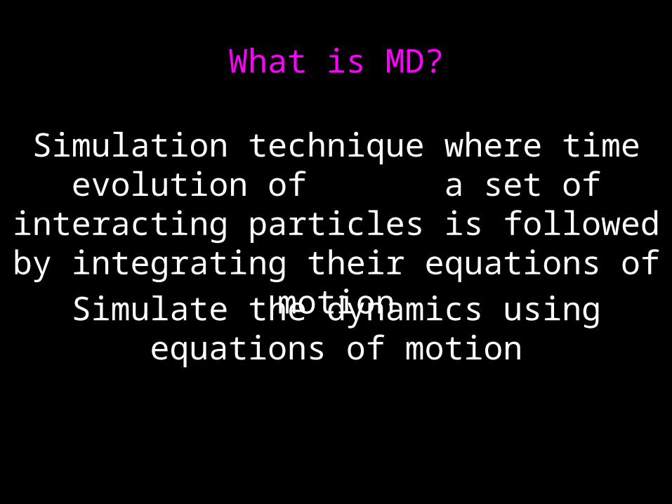
What is MD?
Simulation technique where time evolution of a set of interacting particles is followed by
integrating their equations of motion
Simulate the dynamics using equations of motion
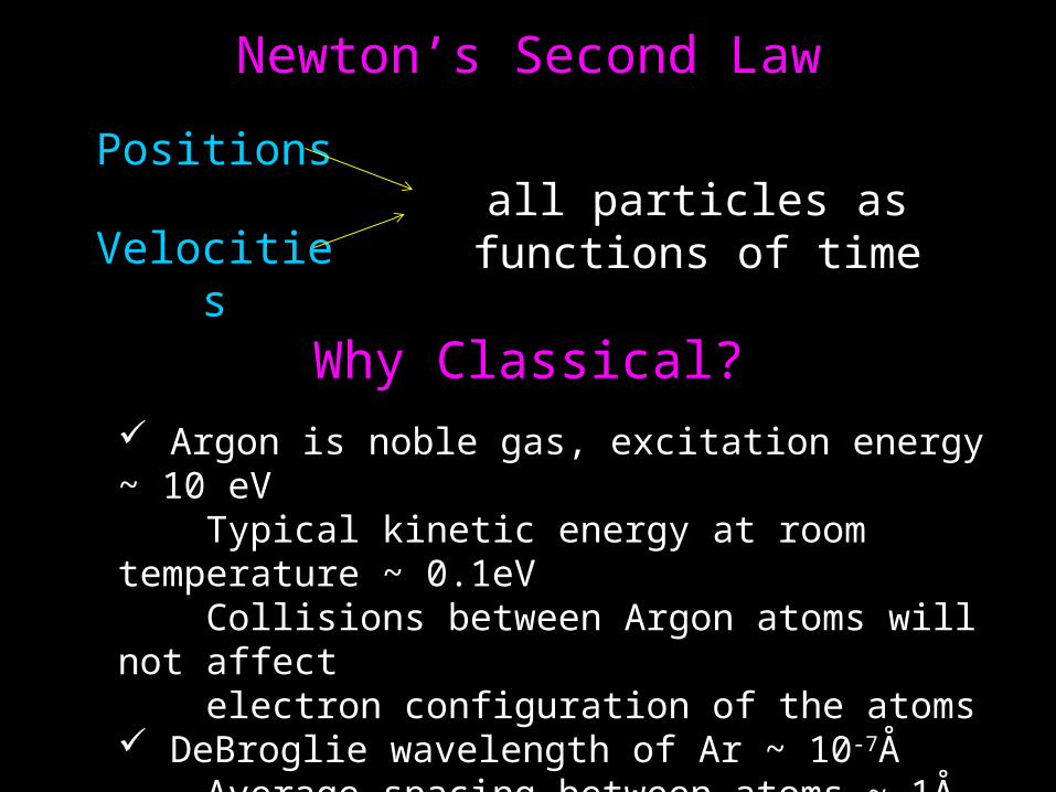
Newton’s Second Law
Positions
Velocitiesall particles as functions of time
Why Classical? Argon is noble gas, excitation energy ~ 10 eV Typical kinetic energy at room temperature ~ 0.1eV Collisions between Argon atoms will not affect electron configuration of the atoms DeBroglie wavelength of Ar ~ 10-7Å Average spacing between atoms ~ 1Å Atomic wavelength << particle separation
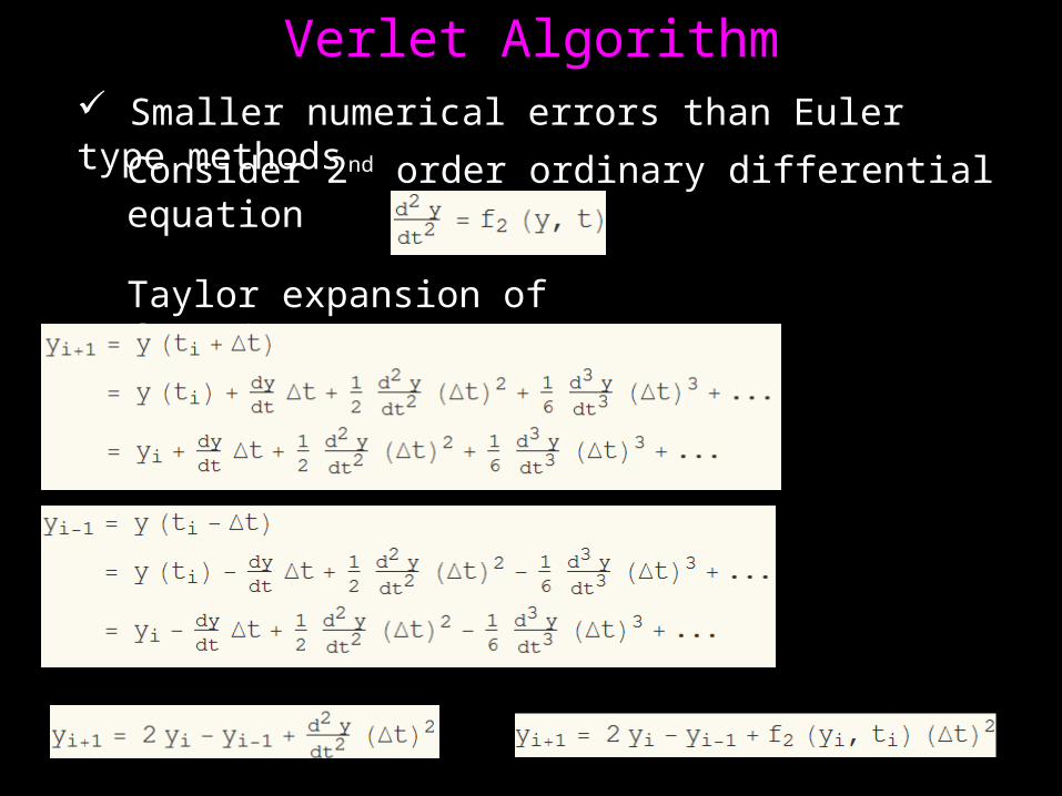
Verlet Algorithm Smaller numerical errors than Euler type methods
Consider 2nd order ordinary differential equation
Taylor expansion of function y(t):
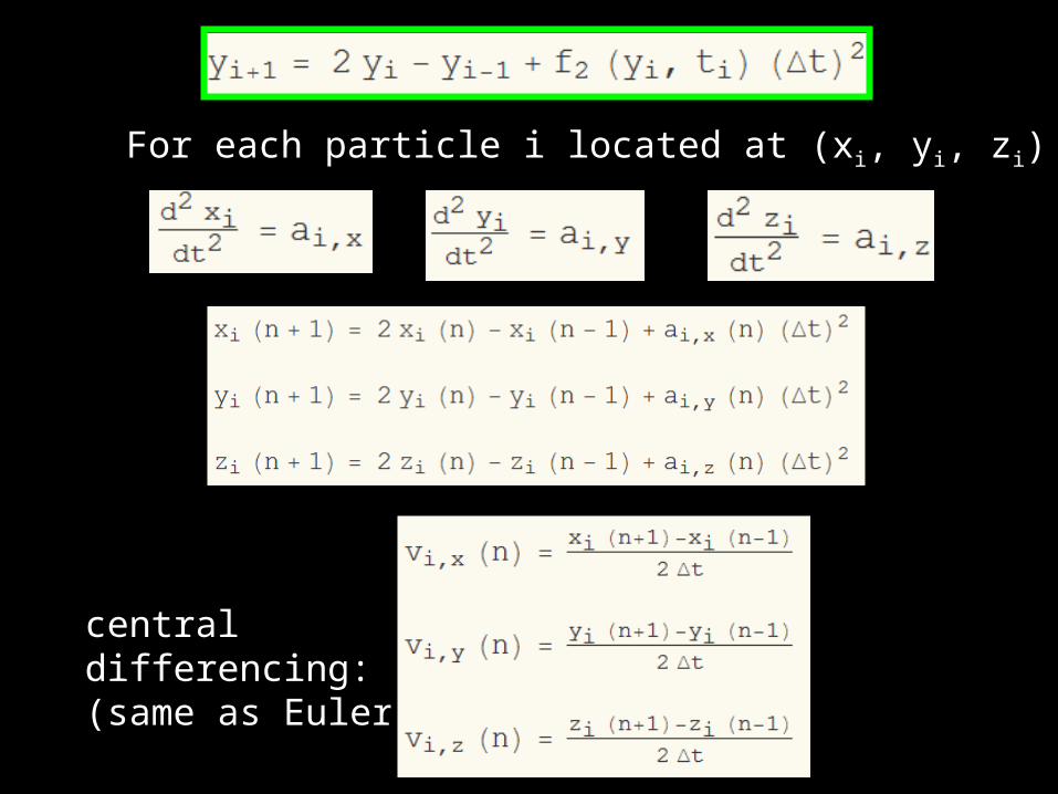
For each particle i located at (xi, yi, zi)
central differencing:(same as Euler)

PotentialMD simulation consist of solving Verlet equations for every particle in system.Each particle experiences a force from all the other particles.To estimate force between any two particles, we need to know the interaction potential.
Large separations,attractive interactions due to Van der Waals,
Close together,repulsion due to overlapof electron clouds
Lennard-Jones potential

Reduced unitset ε = 1,measure all energies in terms of εset σ = 1,measure all lengths in units of σset m = 1,measure all mass in terms of mass of one Ar atom
PARAMETER UNIT
Energy ε
Distance σ
Mass m
Temperature ε/kBPressure ε/σ3
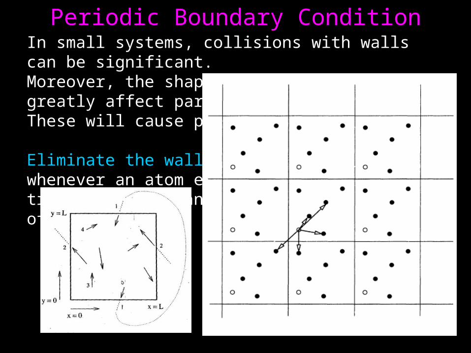
Periodic Boundary ConditionIn small systems, collisions with walls can be significant.Moreover, the shape of small container can greatly affect particle arrangement.These will cause problems.
Eliminate the wall using PBC:whenever an atom encounters a wall, it is transported instantly to the opposite side of the system.
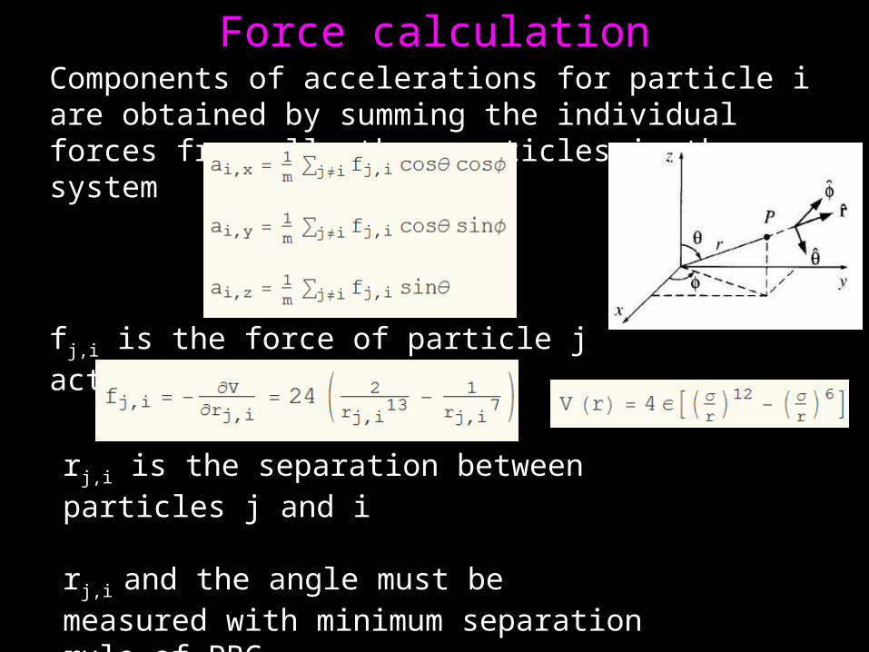
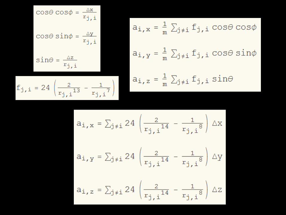
Force calculationComponents of accelerations for particle i are obtained by summing the individual forces from all other particles in the system
fj,i is the force of particle j acting on particle i
rj,i is the separation between particles j and i
rj,i and the angle must be measured with minimum separation rule of PBC

Cutting off potentialAt each time step it is necessary to compute the acceleration of every particle, which involves calculation of many pair forces fj,i
We can save time by assuming that for r > 3.2, interaction potential is zero.
After calculating acceleration components, Find new position of particle i using Verlet method At the same time calculate the new velocities * calculate position at n+1, then calculate velocity at n Check if any particles have left the box. If so, use PCB rules to teleport it. * teleport also previous value of the position since this will be needed in velocity calculation at next time step. * velocity does not need any adjustment
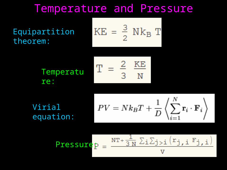
Temperature and Pressure
Equipartition theorem:
Temperature:
Virial equation:
Pressure:
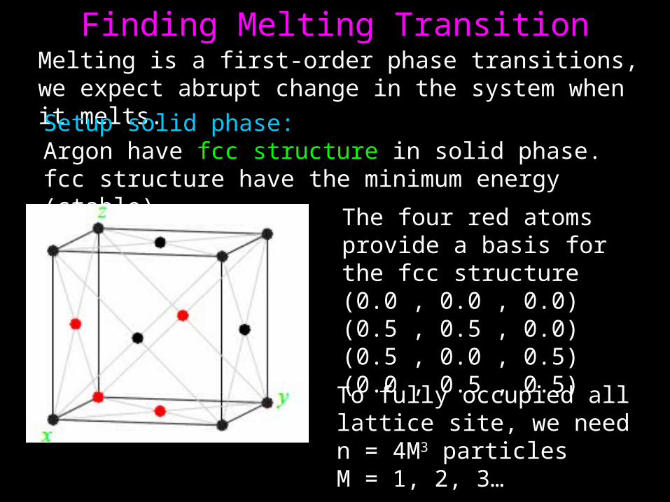
Finding Melting TransitionMelting is a first-order phase transitions, we expect abrupt change in the system when it melts.
Setup solid phase:Argon have fcc structure in solid phase.fcc structure have the minimum energy (stable)
The four red atoms provide a basis for the fcc structure(0.0 , 0.0 , 0.0)(0.5 , 0.5 , 0.0)(0.5 , 0.0 , 0.5)(0.0 , 0.5 , 0.5)
To fully occupied all lattice site, we need n = 4M3 particlesM = 1, 2, 3…

choose n = 32,we shift the basis so the all atoms are inside the volume and none are on the boundaries
(0.25 , 0.25 , 0.25)(0.75 , 0.75 , 0.25)(0.75 , 0.25 , 0.75)(0.25 , 0.75 , 0.75)
Shift the original configuration randomly but with very small magnitude, to kick start the system.To make T as low as possible,start with all particles at rest.

Heating the system:Increase the kinetic energy “by hand”, by increasing the velocities of all the particles by a factor.KE↑, T↑
After increasing the velocities we must then give the system a chance to come into equilibrium
A convenient way to rescale KE is to adjust the location at previous time step in the following way:
If we want to increase the velocity by a factor of 2, we adjustrp so as to make it twice as far from rc
Generally, to rescale the velocity by an amount R:rp* = rc – R(rc – rp)

Measurement of solidness and liquidness:Mean square displacement is given by:
MSD contains information on the atomic diffusivity.If the system is solid, MSD saturates to a finite value,if the system is liquid, MSD grows linearly with time.

Finding Melting TransitionOverview: choose density of box ( manipulating pressure ) setup solid phase initial configuration Verlet method to calculate position for next time step. *calculate other essential information too (velocity, energies, MSD, temperature, pressure) Heat the system and give it some time to reach equilibrium Heat the system again. *repeat for sufficient number of times to heat the system into liquid phase. Mark down the stage where transition occurred Calculate pressure and temperature, average over whole time step of that particular stage. *calculate standard error choose another density and repeat to produce another point for phase diagram

Result
ConclusionSolid-liquid phase diagram for Argon is obtained, although quite rough.
Refinement of parameters is required to obtain better result

Thank you very much!


