Molecular Sieving Hollow Fiber Ceramic Membranes for Reverse OsmosislNanbfiltrdion Applications by: Media and Process Technology Inc. 1155 William Pitt Way Pittsburgh, PA 15238 Contract No. 1425-5-CR-8 l-20870 Water Treatment Technology Program Report No. 40 February 1997 U.S. Department of Interior Bureau of Reclamation P-0. Box 25007, Denver Federal Center Denver, CO 80225-0007
Transcript
Molecular Sieving Hollow Fiber Ceramic Membranes for Reverse
OsmosislNanbfiltrdion Applications
by: Media and Process Technology Inc.
1155 William Pitt Way Pittsburgh, PA 15238
Contract No. 1425-5-CR-8 l-20870
Water Treatment Technology Program Report No. 40
February 1997
U.S. Department of Interior Bureau of Reclamation
P-0. Box 25007, Denver Federal Center Denver, CO 80225-0007
Molecular Sieving Hollow Fiber Ceramic Membranes for Reverse
OsmosidNanofiltration Applications
by: Media and Process Technology Inc.
1155 William Pitt Way Pittsburgh, PA 15238
Contract No. 1425-S-CR-8 l-20870
Water Treatment Technology Program Report No. 40
February 1997
U.S. Department of Interior Bureau of Reclamation
P.O. Box 25007, Denver Federal Center Denver, CO 80225-0007
Bureau of Reclamation Mission Statement
The mission of the Wveau of Reclamation is to manage, develop, and protect water ad dated resources in au environmentally and economically sourxl manner in the interest of the American public,
U. S. Department of the Interior Mission Statement
As the Nation’s principal conservation agency, the Department of the Interior has rspon&ility for most of our nationally+~ed public lands and natural resources. This it&&s fostering wise use of our land and water resources; protecting our fish, wildlife, and biological diversity; preserving the environmental and cultural values of our national parks and historical places; and providing for the enjoyment of life through outdoor recreation. The Department assesses our energy and mineral resources and works to ensure that their development is in the best interests of all our people by encouraging stewardship and citizen participation in their care. The Department also has a major responsibility for American Indian reservation -es and for people who live in islaod territories under U.S. Administration.
Disclaimer
The information contained in this report regarding commercial products or firms may not be used for advertising or promotional purposes and is not to be construed as an endorsement of any product or firm by the Bureau of Reclamation.
The information contained in this report was developed for the Bureau of Reclamation: no warranty as to the accuracy, usefulness, or completeness is express4 or implied,
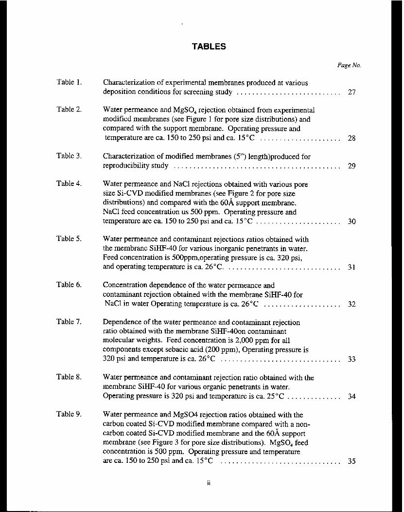
Characterization of experimental membranes produced at various deposition conditions for screening study _ . . . . . . . . f . . . . . . . . . . . . . . . . . 27
Water permeance and MgSO, rejection obtained from experimental modified membranes (see Figure 1 for pore size distributions) and compared with the support membrane. Operating pressure and temperature are ca. 150 to 250 psi and ca. 15°C . _ . . . . . . _ . . . . . . . . . . . . 28
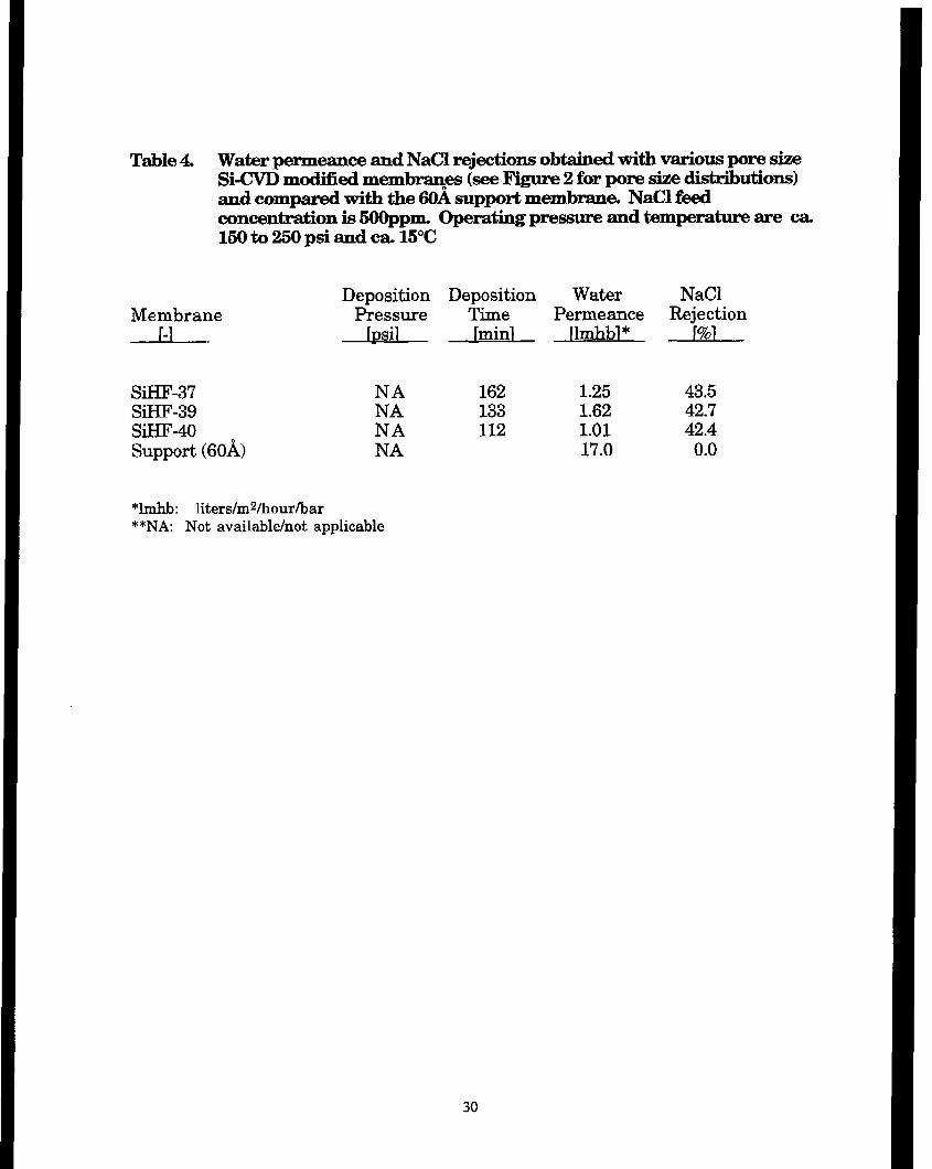
Water permeance and NaCl rejections obtained with various pore size Si-CVD modified membranes (see Figure 2 for pore size distributions) and compared with the 6OA support membrane. NaCl feed concentration us 500 ppm. Operating pressure and temperature are ca. 150 to 250 psi and ca. 15°C . . _ . . . . . . . . . . . . . . . . . .
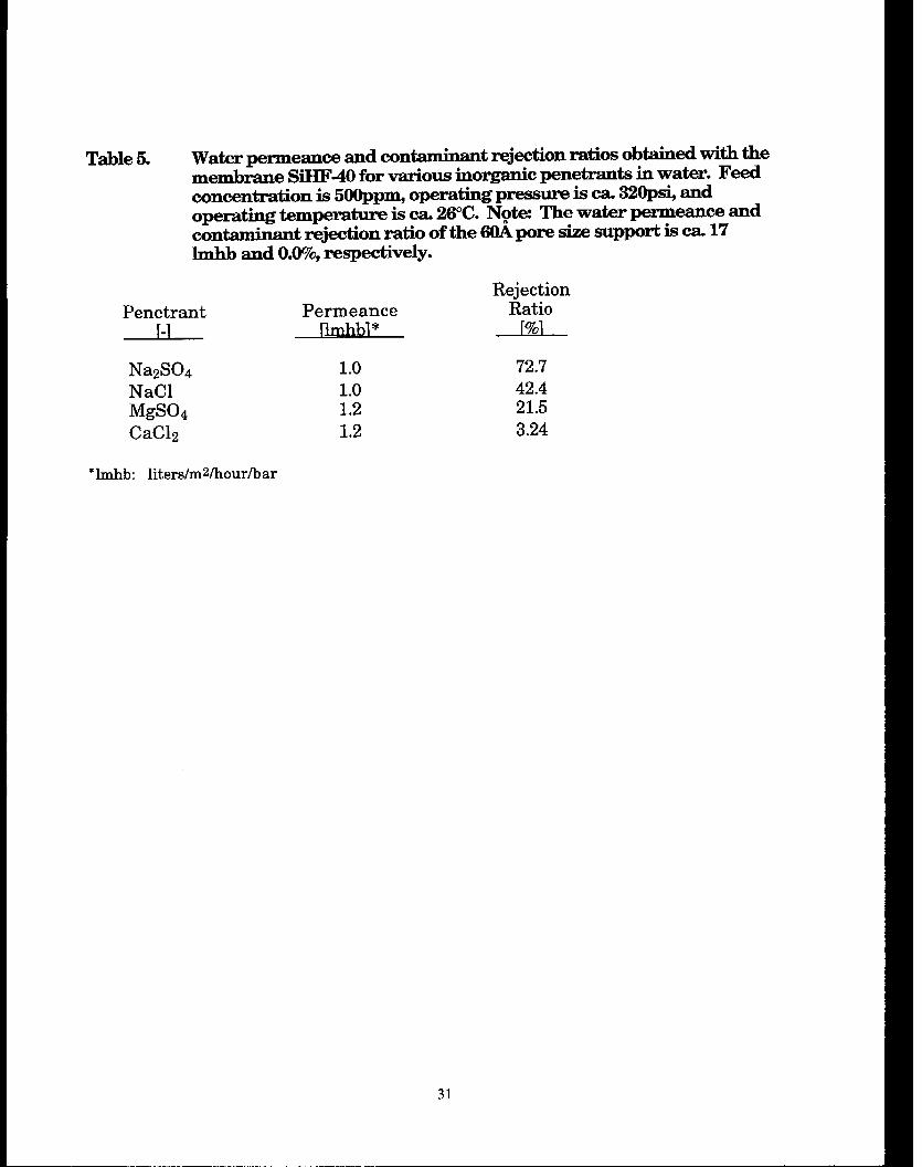
Water permeance and contaminant rejections ratios obtained with the membrane SiHF-40 for various inorganic penetrants in water. Feed concentration is 5OOppm,operating pressure is ca. 320 psi, and operating temperature is ca. 26°C. . . . . . . . . . . . . . . . . . . . . . . . . , . . .
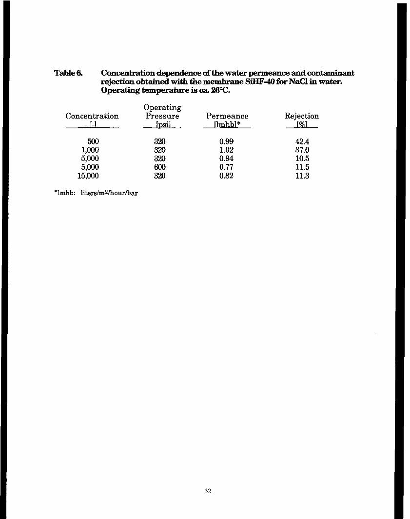
Concentration dependence of the water permeance and contaminant rejection obtained with the membrane SiHF-40 for NaCl in water Operating temperature is ca. 26°C + . . . . . . . . _ . _ _ . . . . . .
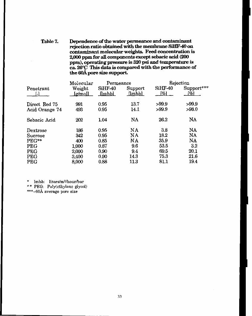
Dependence of the water permeance and contaminant rejection ratio obtained with the membrane SiHF-400n contaminant molecular weights. Feed concentration is 2,000 ppm for all components except sebacic acid (200 ppm), Operating pressure is 320 psi and temperature is ca. 26°C . . _ _ _ *. . . . . . . . . . . . . . . . . . . . . . . .
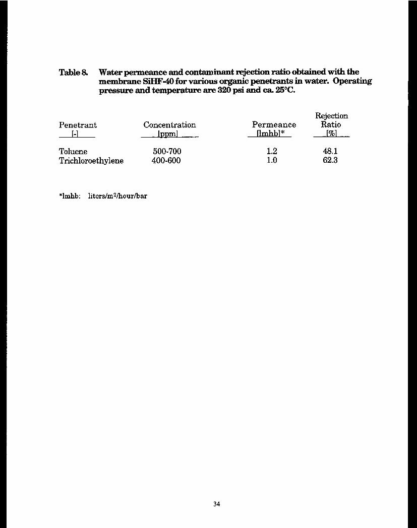
Water penneance and contaminant rejection ratio obtained with the membrane SiHF-40 for various organic penetrants in water. Operating pressure is 320 psi and temperature is ca. 25 “C . . . . . . . . + . . _ .
Water permeance and MgS04 rejection ratios obtained with the carbon coated Si-CVD modified membrane compared with a non- carbon coated Si-CVD modified membrane and the 6OA support membrane (see Figure 3 for pore size distributions). MgSO, feed concentration is 500 ppm. Operating pressure and temperature areca. 150to250psiandca. 15°C . . . . . . . . . . . ..___.............
ii
32 I
33
34
35
TABLES
Page No.
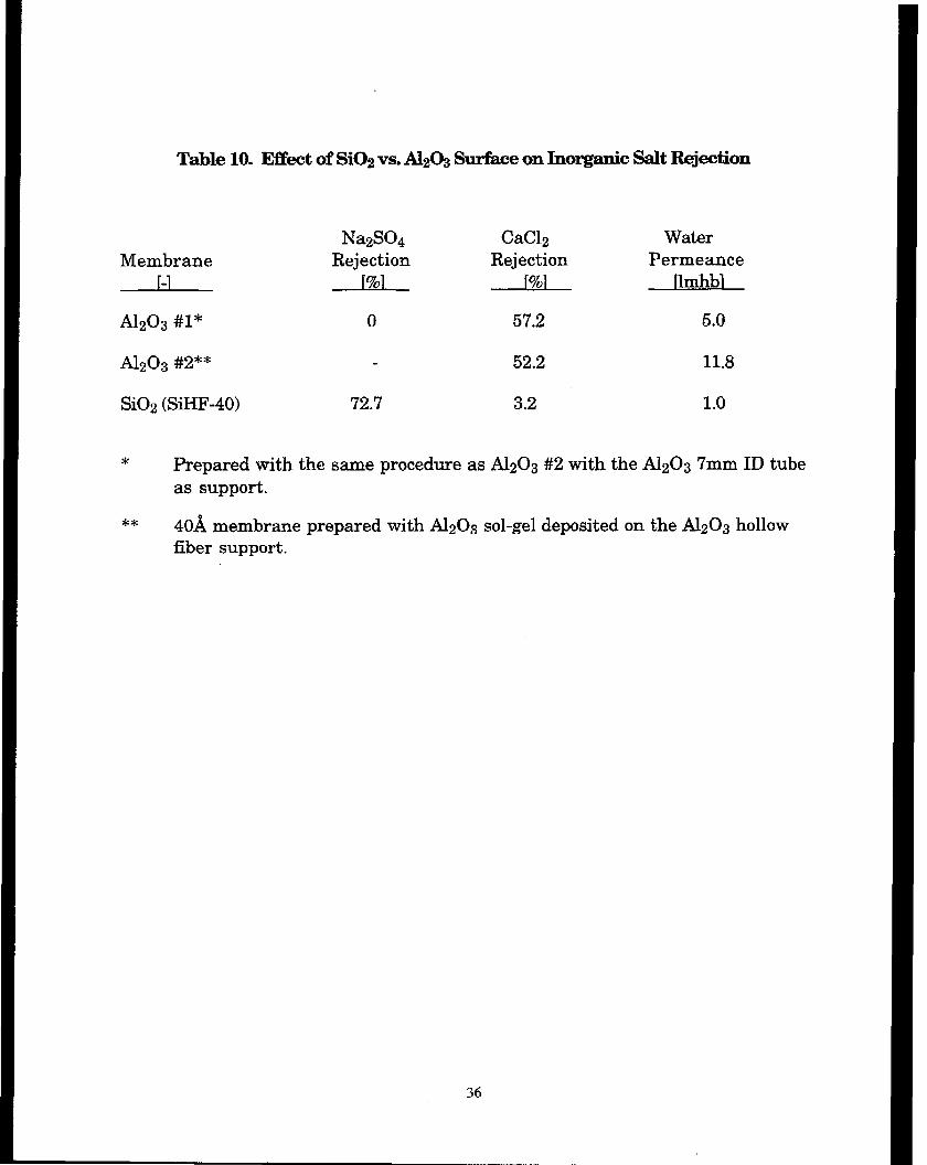
Table 10. Effect of SiO, vs. Al,O, surface on inorganic salt rejection . . . . . . . . . . . . . 36
Table 11. Characterization of modified membrane ( 10” 1ength)produced for scale-upstudy................................................. 37
Table 12. Water permeance and NaCl rejections obtained from modified membranes (see Figure 7 for pore size distributions) produced for scale-up study. NaCl feed concentration is 500ppm. Operating pressure and temperature are ca. 150 to 250 psi and ca. 15°C . . . . _ + _ . . . . 38
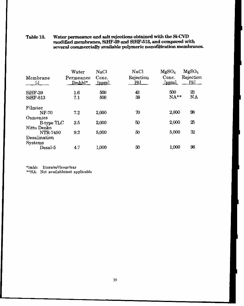
Table 13. Water permeance and salt rejections obtained with the Si-CVD modified membranes, SiHF-39 and SiHF-5 13, and compared with several commercially available polymeric nanofiltration membranes . . . . . 39
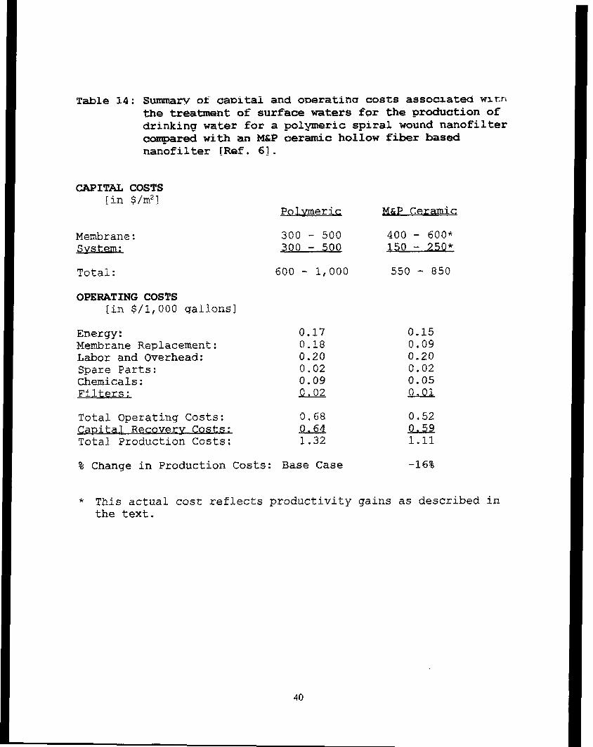
Table 14. Summary of capital and operating costs associated with the treatment of surface waters for the production of drinking water for a polymeric spiral wound nanofilter compared with an M&P ceramic hollow fiber based nanofrlter . . . . . . . . . . . . . . . . . . . . . . . . . . . . . . 40
FIGURES
Page No.
Figure 1. Pore size distributions for several Si-CVD modified M&P ceramic hollow fiber membranes prepared under various CVD conditions . . . . . . . . 41
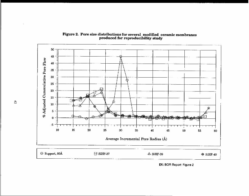
Figure 2. Pore size distributions for several modified ceramic membranes produced for reproducibility study + . . . . . . . . , . . . _ . . . . _ _ . . . . . . . . . . . . . 42
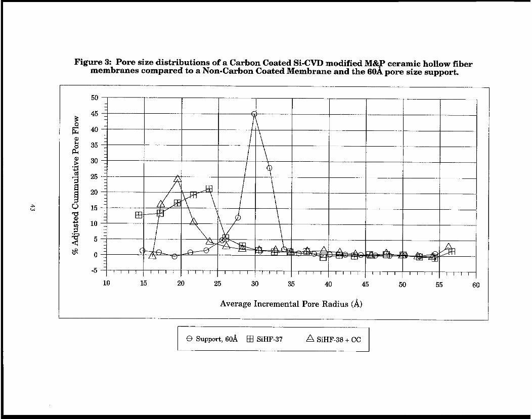
Figure 3. Pore size distributions of a carbon-coated Si-CVD modified M&P ceramic hollow fiber membrane compared to a non-carbon coated membrane and the 6OA pore size support . . _ _ . . . . . . . . . . . . . . . . . . . . . . , 43
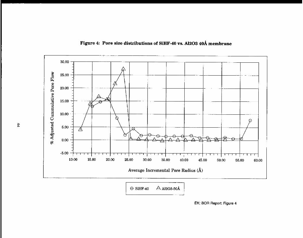
Figure 4. Pore size distributions of SiHF-40 (SiO,) versus Al,O, membranes . . . . + . . 44
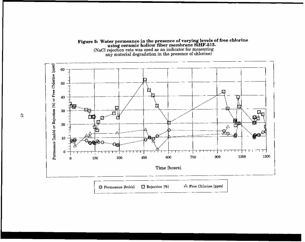
Figure 5. Water permeance in the presence of varying levels of free chlorine using ceramic hollow fiber membrane SiHF-5 13 . . . . . . . . . . . . . . . . . . . . . 45
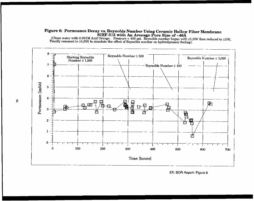
Figure 6. Permeance decay vs. Reynolds number using ceramic hollow fiber membrane SiHF-5 15 with and average pore size of -4OA . . . . . . . . . . . . . . 46
FIGURES
Page No.
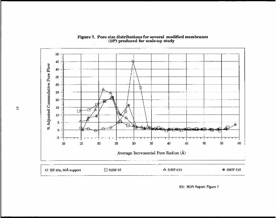
Figure 7. Pore size distributions for several modified membranes( 10”) produced for scale-up study . . f . . . . . . . . . . . . . . . , . . . + . . . . . . . _ . . . . . . . 47
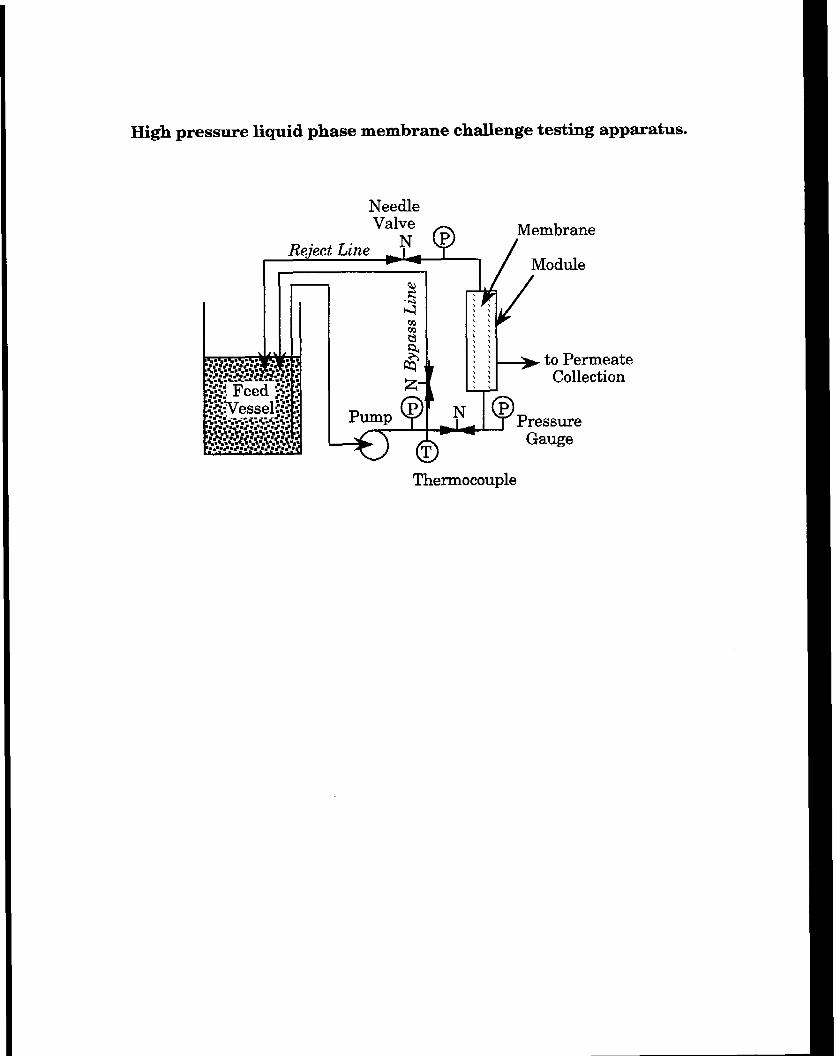
Appendix I. High pressure liquid phase membrane challenge testing apparatus
Appendix II. Molecular weights of the various organic and inorganic penetrants used in this study
iv
ABSTRACT
Hollow fiber ceramic nanofiltration membranes have been prepared with positively (Al,O,) and negatively (SiO,) charged active separating layers and with pore sizes in the neighborhood of 4OA. The rejection of various organic and inorganic solutes from water ranged from 0 to 99% depending upon solute, membrane surface active layer and pore size. Based upon the permeance and rejection characteristics, these membranes would be ideal candidates for RO membrane prefiltration in drinking water and other applications.
Challenge tests were also conducted to demonstrate the oxidant stability and fouling resistance of these membranes. No change in membrane performance was observed in experimental tests conducted in the presence of chlorine (bleach). Further, because these membranes can be fed tube side at high crossflow velocities, high Reynolds numbers and hence good membrane fouling resistance has been experimentally demonstrated. Although our evaluation indicates that the permeance and rejection of the proposed ceramic hollow fiber nanofiltration membrane is comparable to commercially available polymeric nanofilters, the proposed membranes are expected to outperform polymeric NF membranes in actual field tests due to their superior oxidant stability and fouling resistance. Based upon these specific advantages, total production costs for the delivery of drinking water from surface water sources was estimated 16% less for a ceramic filter in comparison to a spiral wound polymeric nanofilter. At the same time a slight reduction in capital costs could also be shown.
Some manufacturing-related parameters were explored briefly in this project. QC test protocols were developed based upon gas permeance and pore size distribution measurement and were used successfully to screen these membranes for the proposed application. Deposition reproducibility was also demonstrated with several membranes prepared under similar conditions. Membrane fabrication scale-up was also briefly studied. No scale-up difficulties can be foreseen, although more refinement may be required to produce a full-scale membrane and module.
V
-
I. INTRODUCTION
Reverse osmosis (RO) and to a lesser degree nanofiltration (NF) are well established membrane technologies for the treatment of water in a variety of applications. Today, only polymeric RO/NF membranes are commercially available. Current research focuses on the development of lower pressure, chlorine resistant membranes that are less susceptible to fouling and can tolerate temperatures in excess of 70 to 80°C. Incremental improvements in any one of these areas will serve the global objectives of the Bureau of Water Reclamation, specifically to (i) reduce membrane system operating costs, (ii) reduce chemical usage, (iii) broaden the spectrum of treatable wastewater and other waste liquid systems, and in general (iv) expand the range of applicability of RO/NF technology. However, fulfilling these objectives via polymeric RO/NF membrane technology will be limited and slow. Typically, improvements in membrane performance in one area result at the expense of performance in other areas. Hence, there are inherent contradictions in the research focuses of polymeric membranes. A new direction in RO/NF membrane technology is required to achieve these goals.
Major deficiencies associated with polymeric RO/NF membranes are listed as follows:
. Excessive fouling due to poor feed flow hydrodynamics
. Low resistance to chlorine and other oxidants important as biocides l Extensive pretreatment/chemical usage and associated waste generation. . For nanofiltration, polymeric membranes commercially available in high fouling
spiral wound configuration only. . Lack of desirable surface charge to reduce fouling potential.
Inorganic oxide based ceramic membranes display a number of performance advantages over commercially available polymeric membranes. Of particular importance in RO and NF applications is the excellent resistance to chlorine, oxidants, radiation, and solvents; the high thermal and pressure stability; and the long reliable life of ceramic membranes. Hence, unlike polymeric membranes, the basic physicochemical properties necessary to produce high quality RO/NF membranes are available from the outset with ceramic materials. However, the high cost, low packing density, and/or poor selectivity renders commercially available ceramic membrane technology economically untenable for RO/NF applications.
To overcome these limitations, Media and Process Technology, Inc. (M&P), teaming with Golden Technologies Company (GTC), has been simultaneously developing a low cost ceramic based hollow fiber support as well as low cost deposition technologies to produce thin ceramic based molecular sieving active membrane layers. This product was originally developed for hydrogen separations from refining waste gases and has been adapted here as an economically viable ROOF membrane.
This innovative product offers the thermal and chemical stability advantages of a ceramic material. In addition, the mechanical stability of the hollow fibers permits high pressure tube side feed. As a result, the hydrodynamic limitations and hence fouling propensity of a ceramic hollow fiber is reduced, in comparison to a polymeric hollow fiber membrane fed shell side or spiral wound membranes. Furthermore, the surface charge of the membrane can be controlled
1
through selection of the proper inorganic oxide surface layer. All of these factors serve to lower the capital and operating costs associated with the pretreatment and membrane cleaning practiced in existing polymeric membrane RO/NF applications. Overall, the development of a molecular sieving hollow fiber for RO/NF applications will simultaneously achieve the current goals of polymeric membrane research, specifically, the development of lower operating pressure, chlorine resistant membranes that are less susceptible to fouling and can tolerate temperatures in excess of 70 to 80 ‘C.
According to preliminary discussions with the Bureau of Reclamation, a robust durable ceramic nanofiltration membrane could be an ideal candidate as an RO prefilter for the production of drinking water from high fouling surface water sources. In this research project, we have prepared a variety of small pore size ceramic membranes via silica chemical vapor deposition (Si-CVD) or A&O, sol gel deposition of a nominal 6OA pore size alumina based hollow fiber support. These membranes were characterized via pore condensation porometry, to determine pore size, and then challenge tested with a variety of inorganic and organic contaminants. Membrane permeance, rejection, fouling resistance and chlorine stability were assessed. In addition, reproducibility of the deposition technique was examined. Finally, membrane performance was compared to that of polymeric membranes on the basis of permeance, rejection, and economics.
We have successfully achieved the stated goals of this project, specifically, we have:
m
(ii)
(iii)
Determined that a ceramic membrane with a pore size of ca. 40A can deliver a good balance between permeance and rejection performance and hence could be an ideal NF membrane candidate for application as a RO prefilter for drinking water production.
Developed a performance database for the permeance and rejection of these membranes using a variety of inorganic salts and organic solutes encountered in water applications. Rejections of up to 99% were achieved depending upon the pore size, surface layer chemistry and the penetrant.
Established that membrane surface charge can be altered through the use of different active layers, i.e.. Al,O, (cationic) vs. SiO, (anionic), to deliver different separation characteristics at the same pore size at a pH=7.
Demonstrated the fouling resistance of these membranes based upon the sensitivity of the membrane permeance and rejection to changes in the feed crossflow velocity (Reynolds number) in the separation of dye from water.
Demonstrated the chlorine stability of these membranes at free chlorine levels of ca. 1 Sppm, well above the free chlorine levels tolerable by polymeric ROLNF membranes of ca. 1 ppm. The test was performed for a period of 1,200 hours.
Demonstrated the scalability and production reproducibility of the proposed ceramic NF membranes.
(vii) Showed that the proposed ceramic NF membrane can deliver permeance and rejection performance comparable to competing polymeric membranes.
(viii) Showed th at th 1 e c ean drinking water production costs can be reduced by at least 16% using the proposed ceramic membrane versus a polymeric membrane due to reductions in pretreatment system requirements, membrane fouling, and higher membrane productivity. The capital costs are comparable to that of a commercial polymeric spiral wound NF system.
Detailed discussion of these results is given below.
-
2. EXPERIMENTAL
2.1 Membrane Synthesis and Characterization
The membranes used in this study were primarily synthesized using a silica chemical vapor deposition method patented by Media and Process Technology Inc. (M&P) [Ref. 11. This technique has been successfully used to produce high temperature ceramic based molecular sieving hydrogen selective membranes. y-alumina (y-Al,OJ ceramic hollow fiber membranes were also prepared to study the effect of surface charge. One of the membranes prepared for this study was also post-treated by applying a thin carbon coating using a technique described in a recent patent [Ref. 23. These membranes were characterized via He and N, gas permeation and pore condensation porometry with equipment described elsewhere [Ref. 3,4,5]. Typical pore size distributions obtained using this technique are shown in Figure 1, for example. Pore sizes less than ca. 20 to 25A are below the detection limit of this equipment. However, the flow contribution below this pore size range can be inferred from the gas permeation results as discussed below. A total of ten membranes were synthesized, characterized, and then challenge tested in this study. Hollow fiber ceramic substrates five inches in length were typically used for the challenge tests. However, two 10” substrates were used to explore the ease of membrane fabrication scale-up.
2.2 Membrane Permeation/Rejection Testing
A schematic of the crossflow membrane filtration apparatus used in this work is shown in Appendix I. In the present work, all membrane permeance and rejection tests were conducted at feed side pressures of 250 to 600 psi and temperatures of 15 to 25°C. Also, low solute concentrations between 450 and 800 ppm and high cross flow velocities (Reynolds numbers in excess of 2,500) were used to minimize concentration polarization. Operating pressures were maintained between 150 and 250 psi, well above the estimated osmotic pressure of approximately 2 to 3 psi. However, several experiments were conducted outside this general operational range to assess membrane fouling resistance. A variety of inorganic and organic solutes were- used as model penetrants and are given in Appendix II. Challenge solutes were obtained from Aldrich Chemical Co. and prepared as pure components in distilled water. Permeate and feed samples were characterized using a Hach Total Dissolved Solids Tester for the inorganic salts. Either chemical oxygen demand (COD) with a Hach Colorimeter or gas chromatography with purge and trap sampling was employed for the determination of organic solute concentrations.
5
-
3. CHARACTERIZATION OF EXPERIMENTAL MEMBRANES
3.1 Pore Size Distribution
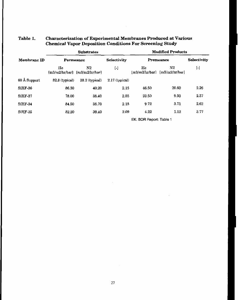
Four experimental membranes (SiHF-34,35,36, and 37) were prepared initially for a screening study to target nanofiltration type applications. They represent a range of products which could possibly be produced via the chemical vapor deposition (CVD) technique developed by M&P. The starting supports used in this study were five inch long, 0.05”ID composite ceramic hollow fibers consisting of a y-Al,O, active layer (3 to 5 pm thick) with pores of about 42 to 688, supported on a 0.27pm pore size a-A&O, support. The pore size distribution of the active layer of this nominal 6OA pore size support is shown in Figure 1. The helium and nitrogen permeance and selectivity (at room temperature) of each of the supports used here are shown in Table 1. After silica chemical vapor deposition, the resultant membranes were again characterized via gas permeation (at 600°C Table 1) and pore condensation porometry (Figure 1).
Following Si-CVD, the pore size distributions of SiHF-34, 36 and 37 were reduced to the range of 26 to 6OA, while the distribution of SiHF-35 was apparently much smaller. Based upon the results in Figure 1, the pore size follows the sequence of SiHF-36>37>34>35. The pore size distributions are consistent with the gas permeation data at 600°C. Specifically, since the gas permeance of SiHF-36 and -37 at 600°C is consistent with Knudsen diffusion, very little, if any, pores likely exist below 26A, the lower resolution limit of the porometer as shown in Figure 1. On the other hand, since the helium to nitrogen selectivity of SiHF-35 is ca. 3.77, higher than that which can be achieved based upon Knudsen diffusion alone (2.65), activated diffusion (through molecular sieving) must be partially contributing to the overall permeance. Hence, it is believed that a significant fraction of the pores of SiHF-35 lie below 26A. Similarly, although the He/N, selectivity of SiHF-34 is somewhat smaller than SiHF-35, it is still higher than the ideal value, so that again, some fraction of the pores in SiHF-34 are likely less than 26A. Overall, these membranes represent a wide range of pore sizes and hence are ideal for a screening study involving the separation of inorganic salts commonly found in water treatment. In this study, MgSO, is used as a model compound.
3.2 Permeance and Rejection
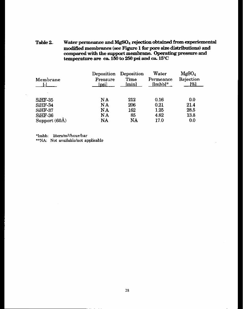
The water permeance and rejection of MgSO, shown in Table 2 were used to characterize the experimental membranes produced above. The water permeance follows the trend established by the gas permeances and the pore size distributions of the membranes. SiHF-36 delivers the highest water flux, i.e., 4.82 lmhb,’ which is about one-third of the support permeance, 17 lmhb. MgSO, rejection of SiHF-36 was 13.8% as compared to the negligible rejection of the support. The Si-CVD modification reduced the pore size from the 40 to 68A range of the support to ~26 to 6OA. In addition, the modification converts the cationic surface of the support (Al,O;) to the anionic surface of the membrane (SiO,) at the pH of the application, -7, Further reduction in the pore size as expected enhanced rejection, i.e., 28.5 and 21.4% for SiHF37 and 34, respectively,
’ lmhb: liters per square meter per hour per bar (liters/m,kdbar).
7
but also yielded a reduction in permeance, i.e., 1.25 and 0.2 1 lmhb, respectively. Surprisingly, although SiHF-35 was likely the smallest pore size membrane, it exhibited no rejection of MgSO,. It is believed that this is due to defects in the membrane. Although a significant fraction of the pores of SiHF-35 fall below 26A, the contribution to the water permeance by these pores was believed to be small and was diluted by permeance contributions from defects in the membrane at pore sizes >>26A. Hence, minimal MgSO, rejection is observed.
Since the degree of rejection is highly dependent upon the pore size, the above analysis indicates that pores of about 408, may be ideal candidates as nanofiltraters applicable to the pretreatment of water to RO type membranes in drinking water and boiler water production applications. The above analysis concludes that the pore size of SiHF-37, at 30 to 60& is a good compromise between permeance and rejection using a SiO, modified ceramic membrane for NF applications. The role of the SiO, surface (compared with the y-Al,O, of the support) is discussed separately in Sec. 4.4 and 5.4.
3.3 Reproducibility Study
A brief study was conducted to determine the reproducibility of our Si-CVD technique for the production a particular membrane. Since SiHF-37 was identified in the screening study conducted in Sets. 3.1 and 3.2 to yield the highest MgSO, rejection, reproducibility tests were conducted at these deposition conditions. Two additional experimental membranes (SiHF-39 and 40) were produced following the preparation condition established for SiHF-37. Their pore size distributions and gas permeances are presented in Figure 2 and Table 3, respectively, for comparison. Water permeances and the rejections of NaCl are listed in Table 4. Although the gas permeances indicate slight differences among these membranes, the pore sizes fall within a similar range, i.e., 28 to 6OA. The reduced gas pertneance of SiHF-40 probably results from contributions from pores less than 4XA. Nevertheless, the ideal gas selectivities of all three membranes fall within the Knudsen regime (2.30 to 2.46) and the water permeances and MgSO, rejections are comparable, indicating that excessive pore size constriction did not occur (i.e*, <26A).
The NaCl rejections of SiHF-37,39 and 40 are nearly identical as shown in Table 4, i.e., 42.4 to 43.5%. Additionally, the water permeance of these membranes are fairly consistent, varying between ca. 1 and 2 hnhb. Water permeance variations between these membranes can likely be accounted for on the basis of differences in the pore size distributions and defects at large pore sizes. Considering that the water permeance is proportional to the fourth power of the pore diameter [Ref. 61, small deviations in the pore size can yield dramatic changes in permeance. Based upon the performance data obtained, it is concluded that the membrane modification procedure implemented by us is reproducible. In addition, although variations in the support were inevitable, these variations were apparently accounted for using this Si-CVD technique resulting in quite similar permeance and rejection behavior. Further, the ideal gas selectivities and the pore size distributions appear to be effective QC parameters for producing on-spec membranes for the target nanofiltration (RO pretreatment) application.
Additional comprehensive performance evaluations with various inorganic and organic solutes in water were conducted with SiHF-40 as a representative membrane and are discussed below.
8
4. PERFORMANCE EVALUATION RESULTS
4.1 Inorganic Salt Rejection
Table 5 compares the water permeance and rejection characteristics of the Si-CVD modified membrane, SiHF-40, for the four inorganic salts, NaCl, MgSO,, CaCl,, and Na,SO, at a feed concentration of 500ppm. The impact of NaCl concentration, ranging from 500 to 15,00Oppm, on the permeance and rejection of SiHF-40 is given in Table 6. The operating pressure and temperature were maintained at 320psi and 26”C, respectively.
4.2 Organic Solute Rejection
A broad range of organic solutes were utilized including two organic dyes, Direct Red 74 and Acid Orange 75; several uncharged hydrophilic species, specifically, dextrose, sucrose and various molecular weight PEGS; a charged low soluble organic, sebacic acid; and uncharged hydrophobic solvents, toluene and trichloroethylene. Molecular weight data for these solutes is given in Appendix II. The water permeance and rejection obtained with SiHF-40 for these materials are shown in Tables 7 and 8. The rejection of the organic dyes, Direct Red 75 and Acid Orange 74, at feed concentrations of O.OOlM exceeds 99% for both the unmodified and Si-CVD modified membranes. For both the uncharged hydrophilic and hydrophobic species, however, the rejection does not approach this level but ranges from 0 to ca. 80%. For all of the tests, the water permeance varies little from about 0.8 to 1.2 hnhb, similar to the results obtained with the inorganic salts.
4.3 Carbon Coated Membrane Performance
Following Si-CVD deposition, membrane SiHF-38 was further coated with a thin carbon film using a technique described elsewhere [Ref, 21. The pore size distribution of this membrane is compared with SiHF-37 in Figure 3. Both membranes were prepared under the same Si-CVD conditions. Figure 3 shows that the carbon coating apparently reduces the pore size of membrane (SiHF-38 vs. -37). Both the water permeance and MgSO, rejection of SiHF-38 is reduced in comparison with SiHF-37 as shown in Table 9.
4.4 A1203 vs. SiO, Surface Layers
The performance of two alumina based membranes were compared to SiHF-40 to determine the influence of surface charge on the membrane rejection characteristics. At neutral pH, the silica deposited SiHF-40 surface is negative versus the positively charged surface of the alumina membranes. Figure 4 shows that the pore size distributions of these membranes are similar. However, the salt rejection of these membranes is dramatically different as Table 10 shows.
9
4.5 Chlorine Stability
The stability of the Si-CVD modified membranes were also examined in the presence of chlorine. In these tests, standard household bleach was added to a solution of 500ppm NaCl in distilled water. The water permeance and NaCl rejection of membrane SiHF-5 13 were measured and are shown in Figure 5 for a ca. 1,200 hour test period. Free chlorine levels, as measured using the DPD Calorimetric Method (Hach Colorimeter), were maintained between 2 and 15ppm throughout the test. In general, the NaCl rejection fluctuated between approximately 20 and 40% while the water permeance fluctuated slightly between ca. 7 and 15 hnhb over the test period.
4.6 Fouling Resistance
Because of the high burst pressures of the experimental membranes used here (>6OOpsi), tube side flow could be practiced. As a result, improved fouling resistance of these membranes should be observed in comparison to shell side fed hollow fiber or spiral wound RO/NF membranes because of the improved feed flow hydrodynamics. In this work, the water permeance and rejection of Acid Orange 74 using SiHF-5 15 were examined at three experimental Reynolds numbers, 1,000,500, and <loo, over a period of several weeks. Figure 6 shows the results. During the first several hours, at high Reynolds numbers, the water permeance dropped from ca. 8 to about 3 to 3.5 lmhb. The permeance remains relatively constant throughout the test until the Reynolds number dropped below 100. At this point, the permeance decayed to < 1 .O lmhb over a four day period. At the same time the rejection dropped dramatically to ca. 50%. The high permeance and rejection were recovered once the Reynolds number was again increased to 1,000.
10
5.1 Rejectior i of Inorganic Salts
5. DISCUSSION
Based upon the results in Table 5 with SiHF-40, it is expected that for any Si-CVD modified membrane prepared under the deposition conditions considered in this research, the inorganic salt rejection will increase as Na,SO, > NaCl > MgSO, > CaCl,. Membrane surface charge and Donnan exclusion can be used to account for the observed trend in the inorganic salt rejection. Since the active separating layer is composed of silica, the point of zero charge is ca. 3 [Ref. 71. At a typical operating pH of ca. 7.0, the surface charge is negative. As a result, given the same cation, sulfate ions will be more effectively rejected in comparison to chloride ions, by virtue of both size exclusion and more importantly electrostatic repulsion (Na$O, > NaCl). However, the lower charge density of the counter ion accounts for the superior rejection of NaCl over both MgSO, and CaCl,. In both cases, the anion is shielded more effectively from the negatively charged surface by the polyvalent cation, yielding the observed trend in the rejection. Similarly, the concentration dependence of the rejection of NaCl is consistent with Donnon exclusion. As noted in Table 6, the rejection of NaCl decreases with increasing concentration from ca. 42% at 500ppm to ca. 10% at 15,OOOppm. Both the ion selectivity and concentration dependence are consistent with Donnan exclusion.
Still, size exclusion effects are apparent from the data presented in Tables 2. In particular, the higher MgSO, rejection observed with SiHF-36 versus SiHF-34 can be attributed to the smaller pore size of the latter membrane (see Figure 1). Hence, although electrostatic repulsion (Donnan exclusion) appears to dominate, size exclusion also plays some role in controlling the salt rejection of the modified membranes. This generalization is more apparent when examined in the light of the rejection of various organic solutes as discussed below. Also, the role of the surface charge is further elaborated in Sec. 5.4 where salt rejections with cationic and anionic surface charge membranes are compared.
5.2 Rejection of Organic Compounds
In comparison to the inorganic salts, excellent rejection of the organic dyes, in excess of 98%, is obtained with both the Si-CVD modified and unmodified membranes as shown in Table 7. Unlike the inorganic salts, the high dye rejection is likely due to steric effects with only minor contributions due to electrostatic repulsion. Two factors support this conclusion. First, since the zero point charge of the alumina based support is ca. 9 at neutral pH, its surface charge is positive, opposite that of the silica modified membranes. As a result, if electrostatic effects played a significant role, one would expect to see a more pronounced difference in dye rejection between the two membranes (as is seen with the salts in Sec. 5.4). Second, in contrast to the dyes, no rejection of any of the inorganic salts by the support is found, even though the support bears a formal positive charge under the test conditions. If Donnan exclusion played the dominant role in the observed dye rejection of the support, then one would also expect to observe at least modest rejection of the inorganic salt by the support. Further experimental evidence of the importance of size exclusion due to steric effects is demonstrated in tests with several more flexible charged and uncharged species.
In comparison to the dyes, other hydrophilic organic solutes, specifically dextrose, sucrose, and various molecular weight PEGS are not rejected as efficiently by either the Si-CVD modified membranes or the unmodified support. As Table 7 shows, the rejection of these solutes by SiHF- 40 increases from about 4% at a molecular weight of 180 (dextrose) to 8 1% at a molecular weight of 8,000 (PEG). Over the same molecular weight range, the performance of the unmodified 608, support is substantially poorer with rejections ranging from 0 to ca. 20%. In the case of these “uncharged” solutes, the rejection is based for the most part upon size exclusion (some surface interaction may occur).
The dicarboxylic acid, sebacic acid, was chosen for study because as a charged flexible penetrant, it is intermediate to the charged, sterically hindered dyes and uncharged, flexible organic solutes (dextrose, PEGS, etc.). As Table 7 shows, this categorization of the penetrants is reflected in the rejection of sebacic acid. Although the water permeance is similar, the rejection of negatively charged sebacic acid by SiHF-40 is 26.2%, well above the 3.8% observed with dextrose even though (i) both molecules are similar in molecular weight and (ii) sebacic acid is more flexible (straight chain) than dextrose (ring structure). Hence, electrostatic repulsion can play a role in significantly increasing the rejection of highly flexible organic penetrants by Si-CVD modified ceramic membranes,
Interestingly, the rejection of both toluene (MW: 92.1) and trichloroethylene (MW: 13 1.4) is significant at ca. 48% and 62%, respectively, using SiHF-40 (Table 8). This is surprising, when compared with the poor 3.8% rejection of dextrose (MW: 180). It is unlikely that steric effects account for this difference, since dextrose is similar in shape and larger in size compared to toluene. In this instance it is suspected that the high rejection of these species is due to their hydrophobicity, compared with the hydrophilic membrane surface. However, further tests with a wider range of hydrophilic and hydrophobic solutes in water will be necessary to clarify the suggested mechanism.
5.3 Performance of a Carbon Coated Membrane
Carbon coating of ceramic membranes has been used in the past as a method to (i) reduce the membrane pore size, (ii) improve the membrane stability in high and low pH regimes, and (iii) alter the surface affinity of the membrane. As expected, carbon coating of a Si-CVD modified membrane shifts the distribution to lower pore sizes as shown in Figure 3. However, the MgSO, rejection of SiHF-38 (carbon coated) is slightly lower than that of SiHF-37 (22.0% vs. 28.5%). There are several possible sources for the lower rejection. First, the carbon coating reduced the surface charge of the membrane. As discussed previously, the negatively charged surface of the Si-CVD modified membranes played a significant role in the rejection of the inorganic salts. Second, as a result of the general reduction in pore size, it is possible that the defects in the membrane play a more significant role in reducing the overall MgSO, rejection in SiHF-38 vs. - 37. Carbon coating, however, yielded only a small reduction in the membrane pertneance. This is reasonable since the pore size reduction was small and likely results from only a monolayer deposition of carbon. Overall, carbon layer deposition as conducted in this test appears to have little impact on the membrane performance. However, further work to more actively cover the
12
membrane surface with carbon to achieve a more dramatic impact on the membrane performance should be conducted.
5.4 Influence of Surface Active Layers
Experimental tests were conducted to assess the impact of surface layer charge with membranes of comparable pore size. Figure 4 shows the pore size distributions of a Si-CVD modified membrane, SiHF-40, compared with two alumina coated membranes. The difference in the rejection characteristics of these membranes, which are compared in Table 10, can be directly related to the surface charge. At neutral pH, the alumina membrane carries a positive surface charge while the silica membrane surface is negative. Hence, based upon Donnan exclusion, the alumina membrane should preferentially reject high charge density polyvalent cations (calcium over sodium) in comparison to the rejection of high charge density polyvalent anions (sulfate over chloride) with the silica membrane. These results show that it is possible to alter the surface charge of a ceramic membrane to actively control membrane performance depending.
5.5 Chlorine Resistance
The modified membrane, SiHF-5 13, showed excellent retention of water permeance and NaCl rejection capability over a ca. 1,200 hour challenge test in the presence of free chlorine levels of 2 to 15ppm as Figure 5 illustrates. Although the rejection rate fluctuates between <20 to >50% during this test period, the fluctuation occurred randomly and is believed to be related to experimental condition irrelevant to the degradation of the membrane. Further, the permeance is relatively stable throughout the test, offering additional evidence of the stability of the membrane. By comparison, the most stable polymeric NF membranes available today (sulfonated polysulfone) will totally fail at free chlorine levels of one ppm in less than 1,000 hours [Ref 93.
Demonstration of the stability of the Si-CVD membranes in the presence of chlorine and other oxidants is important if these membranes are to present an advantage over commercially available RO/NF membranes. Two advantages are of particular importance. First, dechlorination prior to water treatment will not be necessary. Not only will this reduce the pretreatment equipment and chemical requirements, but also will confer the secondary advantage of reduced biofouling. Second, aggressive cleaning with ozone for instance can be practiced to remove organic foulants (humic material to bacteria) from these membranes.
5.6 Membrane Fouling Resistance
Figure 6 shows the advantage of operating a membrane at high Reynolds numbers. Here, the water permeance remains relatively constant over a ca. 480 hour period when the Reynolds number is maintained at > 100. However, below a Reynolds number of 100, the water permeance drops dramatically along with the dye rejection. The decay in the membrane performance is consistent with concentration polarization effects where dye builds up as a “cake
13
layer” due to inadequate turbulence at the membrane surface. Restoration of the membrane performance following an increase in the Reynolds number further demonstrates the importance of maintaining high turbulence at the membrane surface.
This case can be extrapolated to other foulants. One would encounter similar problems with more troublesome foulants such as humic material, biologicals, colloidal silica and iron, CaCO, etc., since these components tend to “salt out” at the membrane surface, thereby irreversibly fouling the membranes. Hence, with these foulants, once fouling has occurred, no increase in crossflow velocity will restore the membrane performance so that cleaning must be conducted, For a typical shell side fed polymeric hollow fiber system, Reynolds numbers are generally less than 100 so that fouling is problematic. Because tube side feed can be practiced with M&P ceramic hollow fibers, much higher Reynolds numbers can be used, Although the threshold Reynolds number may be dependent upon the stream composition, temperature, contaminants, etc., the above experimental result demonstrates that fouling control can be achieved with an appropriate choice of system Reynolds number. As a result, fouling is expected to be significantly reduced.
I 14
6. EXPLORATORY STUDY ON SCALE-UP OF MEMBRANE FABRICATION
The protocol established for fabricating the experimental membranes (5” L) was reproducible as discussed in Sec. 3.3. Since both performance and process evaluation results have been quite favorable, a brief scale-up study was explored at the end of the contract using the established protocol without any modifications. Ten inch ceramic hollow fibers supports, similar in pore size to the five inch supports used previously, were used as supports for membrane fabrication and performance evaluation.
The gas permeances of these membranes are listed in Table 11 along with SiHF-37 as a reference. Figure 7 shows the pore size distributions. Evidently, the support is somewhat different in the 10” versus the 5” hollow tibers, as noted by the lower gas permeance. This may be due to a thicker 608, y-AlzO; layer in the 10” supports. Both SiHF-5 13 and -5 15 show pore sizes ranging from 30 to 62A, falling within the target 4OA range. However, the ideal gas selectivity for SiHF-5 15 is well above that expected from Knudsen diffusion, indicating a significant contribution from pores less than 26A in size. Since previous gas permeance performance evaluation conducted with the five inch membranes indicated that reduced salt rejection occurs under these conditions, this explains the lower NaCl rejection of SiHF-5 15 in comparison to SiHF-37 and -5 13. Hence, as demonstrated previously, gas separation performance of these membranes can be used as a simple QC test to pass/reject the membrane. On the other hand, both the gas permeance and pore size distribution of SiHF-5 13 indicates this product is likely acceptable and is borne out in the water permeance and NaCl rejection of this membrane. The NaCl rejection of SiHF-5 13 listed in Table 12 is 37.&%, which is close to the rejection established for SiHF-37,43.5%. More importantly the water permeance for SiHF-5 13 at 7.12 lmhb is several fold higher than the permeance obtained with the five inch membranes. It is believed that the support thickness may play some role in the determination of the water permeance.
The above exploratory scale-up study indicates that a hollow fiber based ceramic NF membrane could be produced with the established protocol. The established QC criteria reliably, predicts the performance of the membrane, More study is required to fine-tune the deposition conditions; thus, a statistical database of the on-spec yield could be established.
-
7. PERFORMANCE COMPARISON: POLYMERIC VS. CERAMIC NF MEMBRANES
Table 13 shows a comparison of the water permeance and rejection of NaCl for various commercially available polymeric NF membranes [Ref. &] compared with two of the Si-CVD modified ceramic membranes presented in this work, SiHF-39 and SiHF-5 13. Although the rejection of the Si-CVD membranes is somewhat lower than that achieved with the polymeric membranes, the permeance of SiHF-5 13 is quite good. From these results, this initial attempt to prepare NF range ceramic membranes in this project have been very successful. Improvements in membrane performance are expected as the Si-CVD technique is further refined.
Although these ceramic membranes compare favorably with polymeric NF membranes, it should be noted that the permeance of at least the polymeric membranes under actual conditions is significantly poorer, typically less than 2 Imhb. This results from the high fouling that these membranes experience during operation. It is demonstrated in this report that not only is the fouling resistance of the ceramic hollow fiber excellent, but good biofilm control can be achieved because of the superior oxidant stability. Hence, under actual operating conditions, M&P ceramic hollow fiber NF membranes can be expected to outperform their polymeric competition-
-
8. ECONOMIC COMPARISON: POLYMERIC VS. CERAMIC NF MEMBRANES
In this report, we have established that M&P ceramic hollow fiber membranes can be operated in an oxidizing environment under low fouling hydrodynamic conditions. These advantages are expected to yield operating and capital cost reductions in comparison to polymeric membranes. In this section, we compare the advantages of a ceramic over a polymeric NF membrane in terms of performance and economics. Table 14 compares the capital and operating costs of system based upon ceramic and polymeric NF membrane technology for the production of drinking water from a surface water source. What follows is a discussion of the various factors that contribute to these costs.
The capital costs are broken down into two general categories, namely, membranes/modules and system costs.
Membrane Cost: In general, polymeric NF membranes typically cost $300 to 500 per square meter of surface area [Ref. 93. By comparison, it is expected that M&P will be able to deliver a ceramic hollow fiber membrane for approximately $800 to 1,000 per square meter. As we show in Table 13, it is possible to deliver membrane permeances comparable to that achieved with polymeric membranes (see SiHF-5 13). However, it is expected that the productivity of the ceramic membrane will be higher since membrane fouling propensity is lower due to (i) improved flow hydrodynamics which provides improved resistance to inorganic foulants (colloidal silica and iron in particular for surface water sources) and (ii) excellent oxidant resistance which provides a measure of biofouling and other organic contaminant control. These two fouling sources are significant problems for polymeric NF membranes. Based upon our dye rejection data in Figure 6, it is expectedathat significant productivity gains will be realized with a ceramic hollow fiber in comparison to spiral wound membranes which are particularly susceptible to these sources of fouling. Additionally, higher operating pressures can be used with the proposed ceramic membrane. In the economic analysis we have assumed a 50% productivity gain, yielding comparable membrane costs.
System Cost: The overall system cost is also expected to be reduced for two reasons, namely, (i) the higher membrane productivity will yield smaller pump and ancillary equipment requirements and (ii) pretreatment requirements are expected to be reduced. In the economic analysis we have assumed a 50% system cost reduction-
The operating costs are broken down into six general areas, namely, energy, membrane replacement, labor and overhead, spare parts, chemicals, and filters.
Energy: At least three factors contribute to power consumption in membrane systems, specifically, productivity, plugging propensity, and feed cross flow velocity (operating Reynolds number). Higher productivity membranes accomplish the same task while consuming less energy. Hence, a ceramic hollow fiber is expected to yield lower energy consumption. Plugging of the spacers in spiral wound modules due to suspended solids and organic matter is a significant problem in polymeric NF membranes. This fouling yields increased pressure drop
19
and hence power consumption in the module. No such problem is expected with a ceramic hollow fiber (fed tube side) so that again lower energy consumption is expected. Finally, Reynolds numbers of 100 to 500 should be sufficient to yield improved fouling resistance. Overall, energy consumption is expected to be lower for the ceramic hollow fiber. In the economic analysis, we have assumed a 20% energy reduction.
Membrane Replacement: Because of the expected longer lifetime of the ceramic hollow fiber, due to its more robust nature and fouling resistance, it is assumed in the economic analysis that a 50% reduction in membrane replacement costs can be achieved (double the one year life expectancy of polymeric NF membranes [Ref. 91).
Chemicals: Pretreatment and cleaning chemical usage should also be reduced due to the improved fouling resistance of the ceramic membrane. In the economic analysis we have assumed a 50% reduction in chemical usage.
Filters: Prefiltration requirements of the feed to the ceramic membrane is expected to be less extensive since plugging of the membrane tubes is not expected to be significant. For polymeric spiral wound NF membranes, complete removal of total suspended solids is required to prevent plugging at the spacers. In the economic analysis we have assumed a 50% reduction in pre- filtration requirements.
Overall, as the economics in Table 14 show, a 16% reduction in total production costs can be expected to be achieved using M&P ceramic hollow fiber NF membranes for the treatment of surface water for drinking water consumption. This reduction apparently can be achieved at a slight savings in capital equipment costs, also. Hence, the significant advantages of a ceramic hollow fiber membrane, particularly the fouling resistance and oxidant stability, can be expected to deliver significant savings in drinking water and other water treatment applications.
20
9. CONCLUSIONS
Membrane Preparation
1. Ceramic hollow fiber membranes have been prepared as low cost high performance nanofilters for pretreatment for the conventional RO or as a stand-alone filter for water treatment. Pore sizes of approximately 408, and a surface active layer composed of A&O, or SiO, can be fabricated with proprietary technology available at M&P to tailor the properties of the membrane for a particular separation.
2. The lab-scale ceramic hollow fiber nanofilter proposed here has been reproduced satisfactorily. Further, a QC test protocol based upon gas permeance and pore size distribution measurement can be used to adequately screen these membranes for the proposed applications. Scale-up of this technology was briefly studied in this project to demonstrate the scalability of the fabrication protocol, although more refinement may be required to produce a full-scale membrane and module.
Performance Evaluation
3. Both pore size and surface properties are critical to the rejection achieved with the proposed ceramic nanofilter. Pore sizes of ca. 408, yielded rejections of 20 to SO% for various inorganic salts depending upon the membrane surface charge, the nature of the salt, and the concentration levels. On the other hand, negligible rejection was observed for membranes with pore sizes of ca. 6OA. Evidently pore size and electrostatic repulsion is critical. This study suggests a ceramic membrane with a pore size of ca. 4OA offers a good balance between rejection and permeance, based upon the current level of refinement of the deposition technique.
4. A SiO,-based hollow fiber nanofilter with the above characteristics can deliver 73,42, 22, and 3% rejection of Na$O,, NaCl, MgSO,, and CaCl,, respectively, at a concentration of roughly 500 ppm at a pH of 7. Conversely, the Al,O,-based hollow fiber nanofilter with a similar pore size range showed -52, and 0% rejection of CaCl, and Na,SO,, respectively. Evidently, the surface charge of SiO, (anionic) and Al,O, (cationic), in addition to the pore size, plays a critical role in the rejection of these salts.
5. The proposed 4OA membrane, both SiO, and A120;, is more than adequate to completely reject organic dyes, such as Direct Red 75 (MW=991) and Acid Orange 74 (MW=493), likely due to steric hinderance associated with the rigid molecular structure. The proposed membrane shows a low level rejection , i.e., 4, and 18% for neutral organics, such as dextrose (MW=lS6) and sucrose (MW=342), respectively. Rejection of 36 to 81% of PEG ranging from 400 to 8,000 was obtained by the above proposed SiO, membrane.
6. The above proposed SiO, membrane achieved significant rejection of volatile organic contaminants commonly found in water, specifically 48 and 62% rejection of toluene and trichloroethylene. Since the pore size of the membrane is much larger than these compounds, it is believed that the rejection is based upon repulsion of these hydrophobic compounds by the hydrophilic surface of the proposed membrane.
7. The above proposed Al,O, membrane has a water perrneance of ca. 12 lmhb, which is 50 to 300% higher than commercially available polymeric counterparts, not to mention its ability to be operated at a much higher pressure. A SiO, membrane with a similarly high water permeance can also be prepared by chemical vapor deposition of a thin SiO, film onto these Al,O, membranes prepared via sol-gel deposition.
Material Stability and Fouling Resistance
8. The above proposed SiO, membrane has been tested for about 1,200 hours in the presence of 2 to 15 ppm free chlorine. No obvious material degradation was observed using the rejection of NaCl as an index.
9. The proposed membrane displayed no visible fouling in tests conducted at Reynolds numbers of > 100 to >l ,000 using Acid Orange 74 as a model compound in water. When the Reynolds number was reduced to 2 100, the permeance fell precipitously as a result of the significant concentration polarization of the contaminant at the membrane surface. This was accompanied by a dramatic reduction in dye rejection. Membrane permeance and rejection was recovered when the Reynolds number was again increased to > 1,000. Although the threshold Reynolds number could vary depending upon applications, the advantages of our tube side-fed hollow fiber ceramic membrane is obvious. Our hollow fiber ceramic membrane can easily accommodate the required Reynolds number as opposed to the shell-side fed of the polymeric hollow fiber or spiral wound membrane.
Benchmarking Against Polymeric NF
10. The performance of the proposed membrane was comparable to that of polymeric nanofilters, in terms of both permeance and rejection characteristics determined from a single-component evaluation. Because of the superior fouling resistance and oxidant stability, these membranes are expected to outperform polymeric NF membranes in actual field studies.
11. Based upon the specific advantages of fouling resistance and oxidant stability, total production costs for the delivery of drinking water from surface water sources was 16% less for a ceramic nanofilter in comparison to a spiral wound polymeric nanofilter. At.the same time a slight reduction in capital costs could also be shown.
22
10. RECOMMENDATIONS FOR FUTURE WORK
From the results and conclusions obtained in this research effort, further development to prepare a prototype ceramic hollow fiber nanofiltration membrane for field demonstration is recommended. Ln addition, by using the results developed in this work, it is technically feasible and realistic to pursue the development of a ceramic RO membrane. Further detailed recommendations are given below.
1. The SO, or Al,O,-based ceramic hollow fiber nanofilter developed in this project was demonstrated to be effective for the removal of selected organic and inorganic contaminants (single components) commonly encountered in water treatment. Laboratory demonstration using a synthetic stream simulating actual field operation is recommended to determine membrane permeance, removal efficiency and long term stability under a field operation environment.
2. The manufacturing-related parameters for membrane preparation have also been evaluated briefly. No unforseen difficulties are expected for full-scale manufacturing. Therefore, it is recommended that a prototype pilot unit be built to confirm the laboratory results in the field operation.
3. Development of a true ceramic RO appears to be technically feasibly and is recommended as the next application target. Using the newly developed 408, Al,O, ceramic hollow fiber as a precursor for chemical vapor deposition, it is possible that a high performance rugged RO membrane could be produced with a uniform pore size and controlled surface properties.
23
-
1.
2.
3.
4.
5.
6.
7.
8.
9.
REFERENCES
Wu, J.C.S. and Liu, P.K.T., Methodfor Forming Metal Oxide Porous Ceramic Membranes, U.S. Patent 5,415,891, May 16, 1995.
Wu, J.C.S., Gallaher, G.R. and Liu, P.K.T., Carbon-coated Ceramic Membrane, U.S. Patent No. 5.262,198, November 16, 1993.
G.R. Gallaher, P.K.T. Liu, Characterization of ceramic membranes I. Thermal and hydrothermal stabilities of commercial 4OA membranes, J. Memb. Sci, 92,29-44 (1994).
C.L. Lin, D.L. Flowers, P.K.T. Liu, Characterization of ceramic membranes II, Mod$ed commercial membranes with pore size under 4OA, 1. Memb. Sci. 92,45-58 (1994).
J.C.S. Wu, H. Sabol, G. W. Smith, D.L. Flowers, P.K.T. Liu, Characterization of hydrogen- permselective microporous ceramic membranes, J. Memb. Sci, 96,275-287 (1994).
Ho, W.S, and Sirkar, K.K, ed., Membrane Handbook, Van Nostrand Reinhold, New York, 1992..
Hsieh, H.P., Inorganic Membranes for Separation and Reaction, Membrane Science and Technology Series, 3, Elsevier, New York, 1996.
Raman, L.P., Cheryan, M. and Rajagopalan, N., Consider Nanofzltration for Membrane Separations, Chemical Engineering Progress, March, 68-74, (1994).
Private communication, H.L. Fleming, VP Marketing, Zenon Environmental, Inc.
25
-
Table 1. Characterization of Experimental Membranes Produced at Various Chemical Vapor Deposition Conditions For Screening Study
Substrates Modified Products
Membrane ID Permeance Selectivity Premeance Selectivity
He N2 C-1 He N2 r-1 [m3/m2/hr/barl [m3/m2/hr/bar3 [m3/m2/hr/barl [m3/m2/hr/barl
60 ii Support 82.8 (typical) 38.2 (typical) 2.17 (typical)
SiHF-36 86.30 40.20 2.15 46.50 20.60 2.26
SiHF-37 78.00 38.40 2.03 23.50 9.93 2.37
SiHF-34 84.50 38.70 2.18 9.72 3.71 2.62
SiHF-35 32.20 39.40 2.09 4.22 1.12 3.77
EK: BOR Report: Table 1
27
Table 2.. Water permeance and MgSOd rejection obhined from experiemental modified membranes (see IFigure 1 for pore size distributions) and comparedwiththe supportmembrz~~~ Operatingp~ and temperature are CZL 150 to 250 psi and c& 15°C
Membrane r-1
Deposition Deposition Water MgSO4 Pressure Time Permeance Rejection
-,-AWL- rminl llmhbl * -EL-
SiHF-35 SiHF-34 SiHF-37 SiHF-36 Support (6081)
2 212 0.16 0.0 206 0.21 21.4
ii:: 162 1.25 28.5
4.82 13.8 NA 17.0 0.0
*lmhb: liters/mWhoudbar **NA: Not available/not applicable
28
Table 3. Characterization of Modified Membranes (5” length) Produced for Reproducibility Study
Substrates Modified Products
Membrane ID Permeance (25°C) Selectivity Premeance (600°C) Selectivity
He N2 C-l He r-3 [m3/m2/hr/barl [m3/m2/hr/barJ [m3/m2/hr/barI [m3/mt$Wbar]
SiHF-37 78.00 38.40 2.03 23.50 9.93 2.37
SiHF-39 74.70 35.30 2.12 19.90 8.66 2.30
SiHF-40 80.70 37.60 2.15 11.00 4.48 2.46
EK: BOR Report: Table 3
29
Table 4. Water permeance and NaCl mjectiom obtained with varioxxs porn size Si-CVD modified rnembm-es (see Figure 2 for pore size distributions) and compared with the 60A suppork membrane. NaCl feed concentration is 5OOppm. Operating pressure and kmperature are ca 150 to 250 psi and ca 15°C
Membrane [-1
Deposition Deposition Water NaCl Pressure Time Permeance Rejection
*lmhb: liters/d/hour/bar **NA: Not available/not applicable
30
Table 5. Water permeance and contaminant rejection ratios obtained with the membrane SW-40 for various inorganic penetranh ia water. Feed concent;ration is 5OOppm operating pressure is ca. 32Opsi, and operating temperature is c& 26OC. N$~E The water permeance and
rejection x&i0 of the 6OApore size support is ca. 17 and O.O?G, respectively.
Table 6. Concenttdion dependence of the water permeance and corhminant rejection obtained with the membrane SiHF-40 for NaCl in water. Ope~ting~mpenhure is c8.!2WC.
Concentration r-1
Operating Pressure
hi1 Permeance Rejection
llmhbl” J%J-
500 0.99 42.4
;Eiz 5:ooo
E 320 0.94 1.02 37.0 10.5 alo 0.77 11.5
15,000 320 0.82 11.3
*lmhb: liters/mVhour/bar
32
Table 7. Dependence of the water permeance aud contaminant rejection ratio obtahed with the membrane SWF-4-0 on contamhant molecular weights. Feed concentzation is 2,000 ppm for all components except sebacic acid (200 ppm), operating pressure is 320 psi and tempemture is CZL 26”g This data is compared with the performance of tbe 6OApore size support-
3.8 NA 18.2 NA 35.9 NA 53.5 3.2 69.5 20.1 75.3 21.6 81.1 19,4
Table 8, Watir permeance and contaminant rejection ratio obtained with the membrane SiHF4Oforvarious organic penetrants in water. Operating pressure and temperature are 320 psi and ca. 25OC.
Penetrant Concentration r-1 hml
Toluene 500-700 Trichloroethylene 400-600
Permeance Dmhbl *
1.2 1.0
Rejection Ratio
I%1
48.1 62.3
*lmhb: liters/mVhour/bar
34
Table 9: Water permeance and MgSO4 rqjection ratios obtained with the carbon coated Si-CVD modifkd membrane compared $th a non- carbon coated Si-CVD modEed membrane and the 60A support membrane (see Figure 3 for pore size distributions). MgSOd feed concentration is 500ppm. Operating pressure and temperature are ca. 150 to 250psi and ca. 15OC.
Table 10. EXkt of SiOz vs. Al203 Surface on Inorganic Salt Reject&m
Na2S04 CaCl2 Water Membrane Rejection Rejection Permeance
C-l --ml- -"-.&L flmhbl
Al203 #l* 0 57.2 5.0
Al203 #2”* 52.2 11.8
SiO2 (SiHF-40) 72.7 3.2 1.0
* Prepared with the same procedure as Al203 #2 with the Al203 7mm ID tube as support.
** 4OA membrane prepared with Al203 sol-gel deposited on the Al203 hollow fiber support.
36
Table 11. Characterization of Modified Membranes (5” length) Produced for Reproducibility Study
Substrates Modified Products
Membrane ID Permeance (25°C) Selectivity Premeance CSOOW Selectivity
He N2 [-I He N2 L-1 [m3/m2/hr/barl [m3/m2/hr/brl [m3/m2/hr/barl [m3/m2/hr/barl
SiHF-3 7 78.00 38.40 2.03 23.50 9.93 2.37
SiHF-513 32.40 14.80 2.19 31.40 14.80 2.12
SiHF-515 47.10 22.80 2.07 18.90 3.79
EK: BOR Report: Table 11
4.99
31
Table 12. Water permeance and NaCl rejections obtained from modified membntnes (see Figure 7 for pore size distributions) produced for scakup study. NaCl feed concentration is 5OOppm Operating pressure and temperature are c& 150 tt~ 250 psi and ca. 15°C
Membrane I-1
Deposition Deposition Water NaCl Pressure Time Permeance Rejection
hxil [mini nmhbl* r%l
SiHF-37 NA 162 1.25 43.5 SiHF-5 13 NA 94 7S2 37.8 SiHF-515 NA 125 1.97 21.4
*lmhb: liters/mVhour/bar **NA: Not available/not applicable
Table 13. Water permeance and salt rqjections obtained with the Si-CVD modihd membranes, SiHF-39 and SiHF-513, and compzu=d with several commercially available polymeric nanojiltration membranes.
*lmhb: liters/mVhoudbar **NA: Not available/not applicable
39
70
50
50
50
2,000 !B
2,000 25
5,000 32
1,000 gt;
Table 14: Surnmarv of caDital and oDeratina costs associated WItri the treamnt of surface waters for the production of drinking water for a polymeric spiral wound nanofilter compared with an M&P ceramic hollow fiber based nanofilter [Ref. 61.
CAPITAL COSTS [in $/n?2!
Polvmeric M&P Ceramict
Membrane: Svstem:
Total:
300 - 500 400 - 6OO* 300 - 500 150 - 750*
600 - 1,000 550 - 850
OPERATING COSTS [in S/E,000 gallons]
Energy: 0.17 0.15 Membrane Replacement: 0.18 0.09
Labor and overhead: 0.20 0.20 Spare Parts: 0.02 0.02
Chemicals: 0.09 0.05
Filf.erst 0.02 LLLL
Total Operating Costs: 0.68 0.52
1 Re!cOvf?rv Costs. . 9.64 a.59 Total Production Costs: 1.32 1.11
% Change in Production Costs: Base Case -16%
* This actual cost reflects productivity gains as described in the text.
40
P L
Figure 1. Pore size distributions for several Si-CVD modified M&P ceramic hollow fiber membranes prepared under various CVD conditions
50
45
40
35
30
25
20
15
10
5
0
-5
\
I I II L1 I I 1
=i 1 I I I 1 II II III II III1 1 I l I f 1 11 11 11 1 l l I III 1 III II II I II I I I l
10 15 20 25 30 35 40 45 50 55 60
Average Incremental Pore Radius (A)
0 Support, soil B SiHF-36 q SiHF-3’7 A SiHF-34 $t SiHF-35
EK: BOR Repot Figure 1
Figure 2. Pore size distributions for several modified ceramic membranes produced for reproducibility study
50
45
40
35
30
25
20
15
10
5
0
-5
10 25 30 35 40 45
Average Incremental Pore Radius (A>
50 55 60
8 Support, 6OA q SiHF-37 e SiHF-39 $r SiHF-40
EK: BOR Report: Figure 2
Figure 3: Pore size distributions of a Carbon Coated Si-CVD modified M&p ceramic hollow fiber membranes compared to a Non-Carbon Coated Membrane and the 60A pore size support.
50
45
40
35
30
25
20
15
10
5
0
-5 (1 11 ’ ],, , , ,
10 15 20 25 30 35 40 45 50 55 60
Average Incremental Pore Radius (A)
8 Support, 6OA q SiHF-37 bx SiHF-38 + CC
Figure 4: Pore size distributions of SiHF-40 vs. Al203 4OA membrane
30.00
25.00
20.00
15.00
10.00
5.00
0.00
-5.00 I 4 I I I I I I I I I I I 1 I I 1 I I I I I I I I 1 I I I I , I I I I I I I I I
10.00 15.00 20.00 25.00 30.00 35.00 40.00 45.00
Average Incremental Pore Radius (A>
50.00 55.00 60.00
8 SiHF-40 a A1203-5OA
EK: BOR Report: Figure 4
R
Figure 5: Water permeance in the presence of varying levels of free chlorine using ceramic hollow fiber membrane SiHF-513.
(NaCI rejection rate was used as an indicator for measyring any material degradation in the presence of chlorine)
30
20 --
10
i-1
600
Time Ehoursl
8 Permeance IlmhbI El Rejection I%1 4& Free Chlorine [ppml
r
Figure 6: Permeance Decay vs. Reynolds Number Using Ceramic Hollow Fiber Membrane SiHF-515 with An Average Pore Size of -4OA
(Clean water with O.OOlM Acid Orange.. Pressure = 400 psi. Reynolds number began with 21,000 then reduced to 2100, Finally resumed to >_l,OOO to simulate the effect of Reynolds number on hydrodynamic fouling).
8
7
6
5
4
3
2
1
0
I
Starting Reynolds Reynolds Number I 500 Number 2 1,000
\ I
f Reynolds Number z 1,000
I I
0 100 200 300 400 500 600 700
Time [hours] -
EK: BOR Report: Figure 6
Figure 7. Pore size distributions for several modified membranes (109 produced for scale-up study
50
45
40
35
30
25
20
15
10
5
0
-5
10 15 20 25 30 35 40 45
Average Incremental Pore Radius (A)
50 55 60
8 HF-40a, 6OA support H SiHF-37 A SiHF-513 B SiHF-515
EK: BOR Report: Figure 7
APPENDIX1
High pressure liquid phase membrane challenge testing apparatus.
Needle
Membrane
Pressure Gauge
Thermocouple
APPENDMII
Molecular weights of the various organic and ~organic penetmmts usedinthisstudy