64
December 2002 MON08 CYCLONE USER MANUAL ©P&E Microcomputer Systems, Inc., 2001, 2002; All Rights Reserved

December 2002
MON08 CYCLONEUSER MANUAL
©P&E Microcomputer Systems, Inc., 2001, 2002; All Rights Reserved
Purchase Agreement
P&E Microcomputer Systems, Inc. reserves the right to make changes without further notice to any products herein toimprove reliability, function, or design. P&E Microcomputer Systems, Inc. does not assume any liability arising out ofthe application or use of any product or circuit described herein.
This software and accompanying documentation are protected by United States Copyright law and also byInternational Treaty provisions. Any use of this software in violation of copyright law or the terms of this agreementwill be prosecuted.
All the software described in this document is copyrighted by P&E Microcomputer Systems, Inc. Copyright noticeshave been included in the software.
P&E Microcomputer Systems authorizes you to make archival copies of the software and documentation for the solepurpose of back-up and protecting your investment from loss. Under no circumstances may you copy this software ordocumentation for the purpose of distribution to others. Under no conditions may you remove the copyright noticesfrom this software or documentation.
This software may be used by one person on as many computers as that person uses, provided that the software isnever used on two computers at the same time. P&E expects that group programming projects making use of thissoftware will purchase a copy of the software and documentation for each user in the group. Contact P&E for volumediscounts and site licensing agreements.
P&E Microcomputer Systems does not assume any liability for the use of this software beyond the original purchaseprice of the software. In no event will P&E Microcomputer Systems be liable for additional damages, including anylost profits, lost savings or other incidental or consequential damages arising out of the use or inability to use theseprograms, even if P&E Microcomputer Systems has been advised of the possibility of such damage.
By using this software, you accept the terms of this agreement.
MS-DOS & Windows are registered trademarks of Microsoft Corporation. Motorola is a registered trademark ofMotorola, Inc. IBM is a registered trademark of IBM corporation.
P&E Microcomputer Systems, Inc.P.O. Box 2044Woburn, MA 01888617-353-9206www.pemicro.com
Manual version 1.07
MON08 Cyclone User Manual i
P&E MicrocomputerSystems, Inc.
1 INTRODUCTION ............................................................................................................3
2 MON08 CYCLONE HARDWARE .................................................................................3
2.1 MON08 Cyclone Power Supply .....................................................................................................3
2.2 RS232 Communication...................................................................................................................3
2.3 Electromechanical Relays...............................................................................................................4
2.4 Power Connectors...........................................................................................................................4
2.5 Jumper Settings...............................................................................................................................4
2.6 Optional Oscillator .........................................................................................................................5
2.7 Target MON08 Connector ..............................................................................................................6
2.8 Ribbon Cable ..................................................................................................................................8
2.9 Target Power Management.............................................................................................................8
3 TARGET MON08 HEADER PINOUTS .......................................................................13
3.1 68HC908AB .................................................................................................................................13
3.2 68HC908AP..................................................................................................................................14
3.3 68HC908AS..................................................................................................................................15
3.4 68HC908AT .................................................................................................................................15
3.5 68HC908AZ .................................................................................................................................16
3.6 68HC908BD .................................................................................................................................17
3.7 68HC908EY .................................................................................................................................18
3.8 68HC908GP..................................................................................................................................18
3.9 68HC908GR16 .............................................................................................................................19
3.10 68HC908GR4/8 ............................................................................................................................20
3.11 68HC908GT .................................................................................................................................21
3.12 68HC908GZ .................................................................................................................................21
3.13 68HC908JB1/8 .............................................................................................................................22
3.14 68HC908JB16 ..............................................................................................................................23
3.15 68HC908JG ..................................................................................................................................24
3.16 68HC908JK ..................................................................................................................................24
3.17 68HC908JL...................................................................................................................................25
3.18 68HC908KX .................................................................................................................................26
3.19 68HC908LD .................................................................................................................................27
3.20 68HC908LJ...................................................................................................................................27
3.21 68HC908MR16/32 .......................................................................................................................28
3.22 68HC908QT .................................................................................................................................29
3.23 68HC908QY .................................................................................................................................30
3.24 68HC908RF..................................................................................................................................30
3.25 68HC908RK .................................................................................................................................31
3.26 68HC908SR..................................................................................................................................32
4 STAND-ALONE PROGRAMMER OPERATION .......................................................33
ii MON08 Cyclone User Manual
P&E MicrocomputerSystems, Inc.
4.1 MON08 Cyclone Buttons ............................................................................................................ 33
4.2 MON08 Cyclone LED Indicators ................................................................................................ 33
4.3 Example ....................................................................................................................................... 34
5 STAND-ALONE PROGRAMMER CONFIGURATION.............................................35
5.1 Command Line Parameters.......................................................................................................... 36
5.2 Port Pin Settings........................................................................................................................... 36
5.3 Baud Rate and Security Settings.................................................................................................. 37
5.4 Target Power Down/Up Delay in Milliseconds........................................................................... 37
5.5 Specify Programming Algorithm and S-Record.......................................................................... 38
5.6 Programming Operations ............................................................................................................. 38
5.7 Image Description........................................................................................................................ 39
5.8 Save Image................................................................................................................................... 39
5.9 Stand-Alone Operation Procedure ...............................................................................................39
6 PC-HOSTED DEBUG/PROGRAMMING SOFTWARE..............................................40
6.1 P&E Microcomputer Systems Software ...................................................................................... 40
6.2 Metrowerks Software................................................................................................................... 43
6.3 Target Connection And Security Dialog ..................................................................................... 48

MON08 Cyclone User Manual 3
P&E MicrocomputerSystems, Inc. MON08 CYCLONE
1 INTRODUCTIONThe MON08 CYCLONE is designed to control the Motorola 68HC908 targetsin-circuit via the Monitor ROM (MON08 Port). The CYCLONE acts as adebugging/programming tool. It communicates with PC through a standardRS-232 port. In addition, the MON08 CYCLONE can function as a Stand-Alone Programmer. Once configured properly, it can program target devicesindependent of a PC.
Some of the features that make the MON08 CYCLONE versatile are:
a. Software configurable port pin settings for Monitor ROM entrance.
b. Works with 3.3V and 5V targets with internal bus frequency ranges from1MHz to 8MHz.
c. Automatically detects target internal bus frequency and sets communicationsbaud rate.
d. Automatically cycles target power using electromechanical relays duringsecurity protocol.
e. Provides 5V 9.8304 MHz oscillator signal to overdrive target crystal and RCclock circuitry.
2 MON08 CYCLONE HARDWARE
2.1 MON08 Cyclone Power Supply
The MON08 CYCLONE requires a regulated 5V DC Center Positive powersupply with 2.5/5.5mm female plug. The MON08 CYCLONE derives itspower from the Power Jack located beside the DB9 female connector.
2.2 RS232 Communication
The MON08 CYCLONE provides a DB9 Female connector to communicatewith a host computer through the RS232 communication (57600 Baud, 8 Databits, No parity, 1 Stop bit).
4 MON08 Cyclone User Manual
P&E MicrocomputerSystems, Inc.MON08 CYCLONE
2.3 Electromechanical Relays
Inside the MON08 CYCLONE, two electromechanical relays are used to cycletarget power. The specifications of the relays are as following:
Maximum switched power: 30W or 125 VAMaximum switched current: 1AMaximum switched voltage: 150VDC or 300VACUL Rating: 1A at 30 VDC
1A at 125 VAC
2.4 Power Connectors
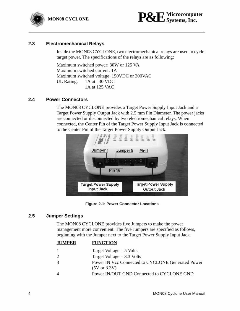
The MON08 CYCLONE provides a Target Power Supply Input Jack and aTarget Power Supply Output Jack with 2.5 mm Pin Diameter. The power jacksare connected or disconnected by two electromechanical relays. Whenconnected, the Center Pin of the Target Power Supply Input Jack is connectedto the Center Pin of the Target Power Supply Output Jack.
Figure 2-1: Power Connector Locations
2.5 Jumper Settings
The MON08 CYCLONE provides five Jumpers to make the powermanagement more convenient. The five Jumpers are specified as follows,beginning with the Jumper next to the Target Power Supply Input Jack.
JUMPER FUNCTION
1 Target Voltage = 5 Volts2 Target Voltage = 3.3 Volts3 Power IN Vcc Connected to CYCLONE Generated Power
(5V or 3.3V)4 Power IN/OUT GND Connected to CYCLONE GND
MON08 Cyclone User Manual 5
P&E MicrocomputerSystems, Inc. MON08 CYCLONEMON08 CYCLONE
5 Power OUT Vcc Connected to MON08 Connector Pin 15
Jumper 1 and Jumper 2 notifies the MON08 CYCLONE of the target MCUvoltage. Either Jumper 1 or Jumper 2 must be shorted, but not both.
Jumper 3 and Jumper 4 are provided to enable the target board to draw powerfrom the CYCLONE so that the “POWER IN” jack is not needed. In this case,the target power has to be either DC 5V (Jumper 1) or 3.3V (Jumper 2).
Jumper 5 connects Pin 15 of the MON08 connector with the center pin of theTarget Power Supply Output Jack. If Jumper 4 and Jumper 5 are shorted thetarget may obtain power through the ribbon cable and the Target Power SupplyJack is not needed.
2.6 Optional Oscillator
The MON08 CYCLONE provides a 5V 9.8304 MHz oscillator clock signal toPin 13 of the MON08 Connector. If the target is a 5V system, the user may usethis clock signal to overdrive the target RC or crystal circuitry. If this signal isnot used, just leave Pin 13 of the target MON08 header unconnected.
Please note that if the target already uses an oscillator as its clock, theCYCLONE will NOT be able to overdrive it. The clock should have sufficientdrive to be used with a target system even if the target system has an RC circuitor crystal connected.
6 MON08 Cyclone User Manual
P&E MicrocomputerSystems, Inc.MON08 CYCLONE
2.7 Target MON08 Connector
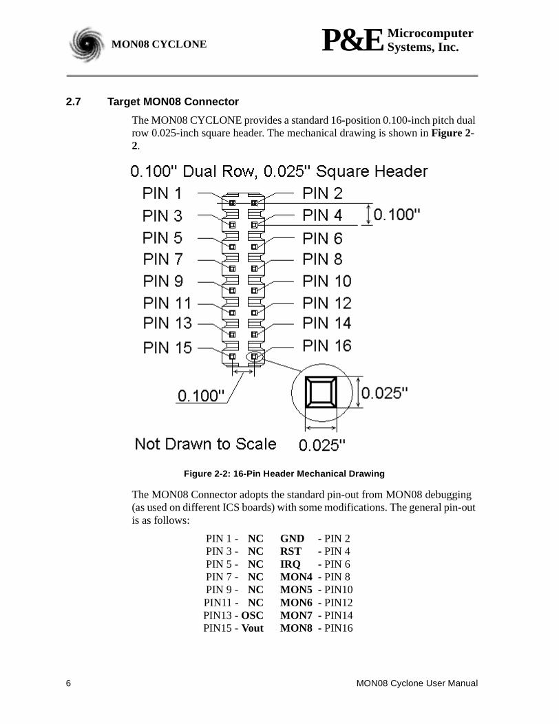
The MON08 CYCLONE provides a standard 16-position 0.100-inch pitch dualrow 0.025-inch square header. The mechanical drawing is shown inFigure 2-2.
Figure 2-2: 16-Pin Header Mechanical Drawing
The MON08 Connector adopts the standard pin-out from MON08 debugging(as used on different ICS boards) with some modifications. The general pin-outis as follows:
PIN 1 - NC GND - PIN 2PIN 3 - NC RST - PIN 4PIN 5 - NC IRQ - PIN 6PIN 7 - NC MON4 - PIN 8PIN 9 - NC MON5 - PIN10PIN11 - NC MON6 - PIN12PIN13 -OSC MON7 - PIN14PIN15 -Vout MON8 - PIN16
MON08 Cyclone User Manual 7
P&E MicrocomputerSystems, Inc. MON08 CYCLONEMON08 CYCLONE
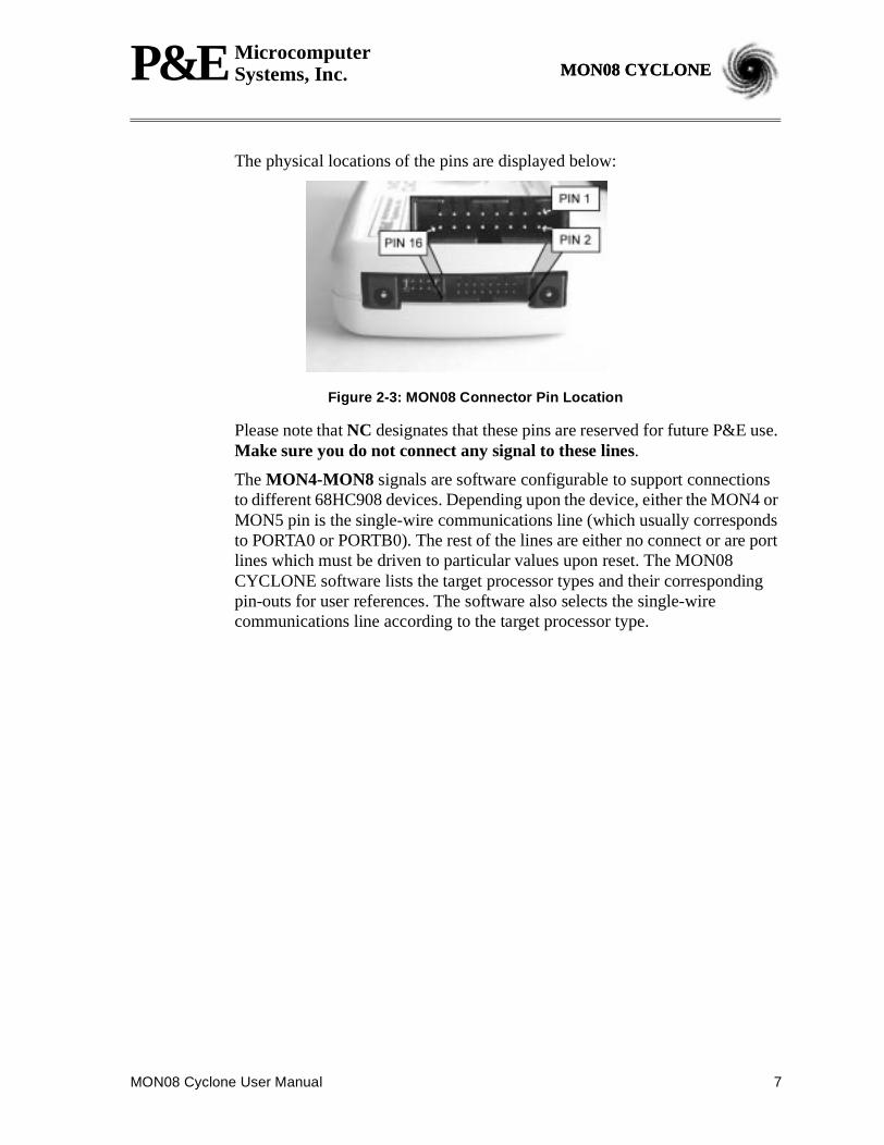
The physical locations of the pins are displayed below:
Figure 2-3: MON08 Connector Pin Location
Please note thatNC designates that these pins are reserved for future P&E use.Make sure you do not connect any signal to these lines.
TheMON4-MON8 signals are software configurable to support connectionsto different 68HC908 devices. Depending upon the device, either the MON4 orMON5 pin is the single-wire communications line (which usually correspondsto PORTA0 or PORTB0). The rest of the lines are either no connect or are portlines which must be driven to particular values upon reset. The MON08CYCLONE software lists the target processor types and their correspondingpin-outs for user references. The software also selects the single-wirecommunications line according to the target processor type.
8 MON08 Cyclone User Manual
P&E MicrocomputerSystems, Inc.MON08 CYCLONE
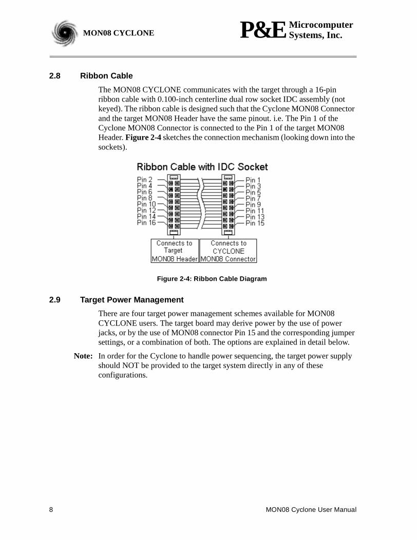
2.8 Ribbon Cable
The MON08 CYCLONE communicates with the target through a 16-pinribbon cable with 0.100-inch centerline dual row socket IDC assembly (notkeyed). The ribbon cable is designed such that the Cyclone MON08 Connectorand the target MON08 Header have the same pinout. i.e. The Pin 1 of theCyclone MON08 Connector is connected to the Pin 1 of the target MON08Header.Figure 2-4sketches the connection mechanism (looking down into thesockets).
Figure 2-4: Ribbon Cable Diagram
2.9 Target Power Management
There are four target power management schemes available for MON08CYCLONE users. The target board may derive power by the use of powerjacks, or by the use of MON08 connector Pin 15 and the corresponding jumpersettings, or a combination of both. The options are explained in detail below.
Note: In order for the Cyclone to handle power sequencing, the target power supplyshould NOT be provided to the target system directly in any of theseconfigurations.
MON08 Cyclone User Manual 9
P&E MicrocomputerSystems, Inc. MON08 CYCLONEMON08 CYCLONE
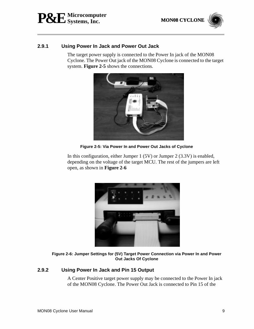
2.9.1 Using Power In Jack and Power Out Jack
The target power supply is connected to the Power In jack of the MON08Cyclone. The Power Out jack of the MON08 Cyclone is connected to the targetsystem.Figure 2-5 shows the connections.
Figure 2-5: Via Power In and Power Out Jacks of Cyclone
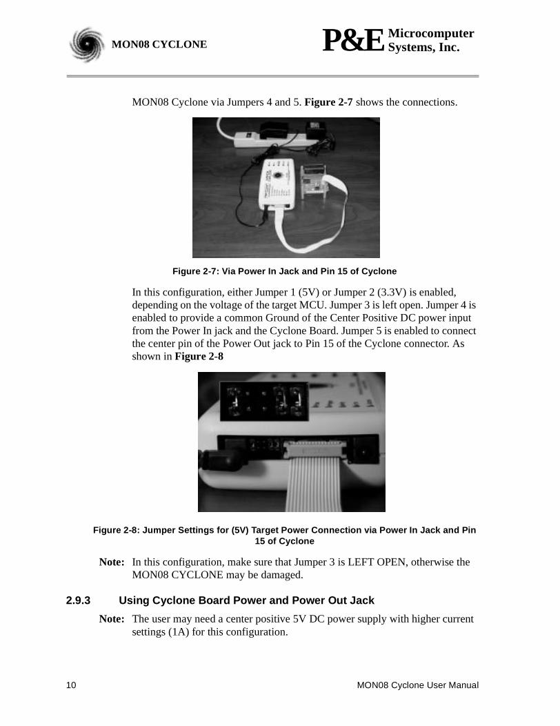
In this configuration, either Jumper 1 (5V) or Jumper 2 (3.3V) is enabled,depending on the voltage of the target MCU. The rest of the jumpers are leftopen, as shown inFigure 2-6
Figure 2-6: Jumper Settings for (5V) Target Power Connection via Power In and PowerOut Jacks Of Cyclone
2.9.2 Using Power In Jack and Pin 15 Output
A Center Positive target power supply may be connected to the Power In jackof the MON08 Cyclone. The Power Out Jack is connected to Pin 15 of the
10 MON08 Cyclone User Manual
P&E MicrocomputerSystems, Inc.MON08 CYCLONE
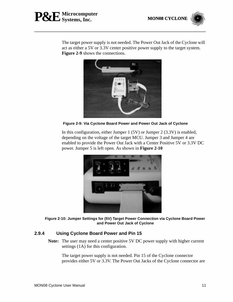
MON08 Cyclone via Jumpers 4 and 5.Figure 2-7 shows the connections.
Figure 2-7: Via Power In Jack and Pin 15 of Cyclone
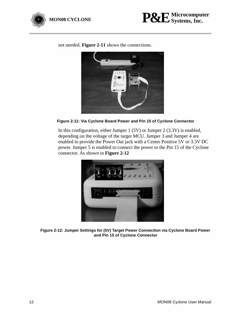
In this configuration, either Jumper 1 (5V) or Jumper 2 (3.3V) is enabled,depending on the voltage of the target MCU. Jumper 3 is left open. Jumper 4 isenabled to provide a common Ground of the Center Positive DC power inputfrom the Power In jack and the Cyclone Board. Jumper 5 is enabled to connectthe center pin of the Power Out jack to Pin 15 of the Cyclone connector. Asshown inFigure 2-8
Figure 2-8: Jumper Settings for (5V) Target Power Connection via Power In Jack and Pin15 of Cyclone
Note: In this configuration, make sure that Jumper 3 is LEFT OPEN, otherwise theMON08 CYCLONE may be damaged.
2.9.3 Using Cyclone Board Power and Power Out Jack
Note: The user may need a center positive 5V DC power supply with higher currentsettings (1A) for this configuration.
MON08 Cyclone User Manual 11
P&E MicrocomputerSystems, Inc. MON08 CYCLONEMON08 CYCLONE
The target power supply is not needed. The Power Out Jack of the Cyclone willact as either a 5V or 3.3V center positive power supply to the target system.Figure 2-9 shows the connections.
Figure 2-9: Via Cyclone Board Power and Power Out Jack of Cyclone
In this configuration, either Jumper 1 (5V) or Jumper 2 (3.3V) is enabled,depending on the voltage of the target MCU. Jumper 3 and Jumper 4 areenabled to provide the Power Out Jack with a Center Positive 5V or 3.3V DCpower. Jumper 5 is left open. As shown inFigure 2-10
Figure 2-10: Jumper Settings for (5V) Target Power Connection via Cyclone Board Powerand Power Out Jack of Cyclone
2.9.4 Using Cyclone Board Power and Pin 15
Note: The user may need a center positive 5V DC power supply with higher currentsettings (1A) for this configuration.
The target power supply is not needed. Pin 15 of the Cyclone connectorprovides either 5V or 3.3V. The Power Out Jacks of the Cyclone connector are
12 MON08 Cyclone User Manual
P&E MicrocomputerSystems, Inc.MON08 CYCLONE
not needed.Figure 2-11shows the connections.
Figure 2-11: Via Cyclone Board Power and Pin 15 of Cyclone Connector
In this configuration, either Jumper 1 (5V) or Jumper 2 (3.3V) is enabled,depending on the voltage of the target MCU. Jumper 3 and Jumper 4 areenabled to provide the Power Out jack with a Center Positive 5V or 3.3V DCpower. Jumper 5 is enabled to connect the power to the Pin 15 of the Cycloneconnector. As shown inFigure 2-12
Figure 2-12: Jumper Settings for (5V) Target Power Connection via Cyclone Board Powerand Pin 15 of Cyclone Connector
MON08 Cyclone User Manual 13
P&E MicrocomputerSystems, Inc. MON08 CYCLONEMON08 CYCLONE
3 TARGET MON08 HEADER PINOUTSThis chapter details the MON08 connector signals according to the individualtarget MCU types.
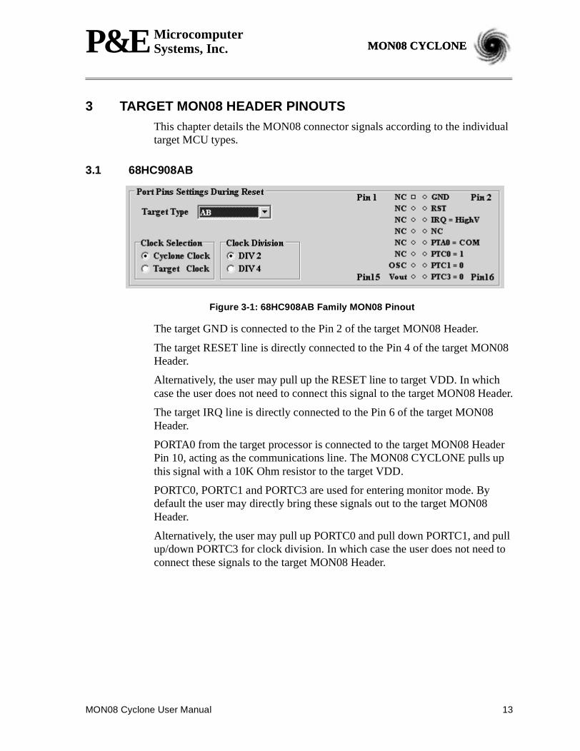
3.1 68HC908AB
Figure 3-1: 68HC908AB Family MON08 Pinout
The target GND is connected to the Pin 2 of the target MON08 Header.
The target RESET line is directly connected to the Pin 4 of the target MON08Header.
Alternatively, the user may pull up the RESET line to target VDD. In whichcase the user does not need to connect this signal to the target MON08 Header.
The target IRQ line is directly connected to the Pin 6 of the target MON08Header.
PORTA0 from the target processor is connected to the target MON08 HeaderPin 10, acting as the communications line. The MON08 CYCLONE pulls upthis signal with a 10K Ohm resistor to the target VDD.
PORTC0, PORTC1 and PORTC3 are used for entering monitor mode. Bydefault the user may directly bring these signals out to the target MON08Header.
Alternatively, the user may pull up PORTC0 and pull down PORTC1, and pullup/down PORTC3 for clock division. In which case the user does not need toconnect these signals to the target MON08 Header.
14 MON08 Cyclone User Manual
P&E MicrocomputerSystems, Inc.MON08 CYCLONE
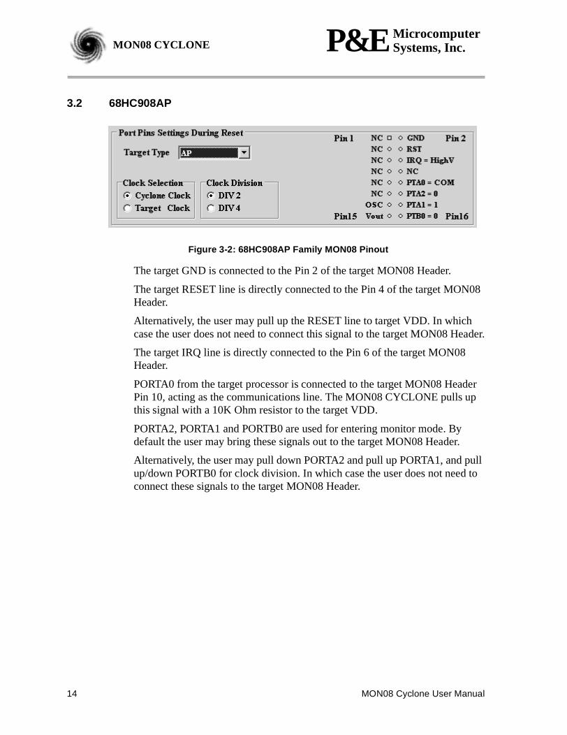
3.2 68HC908AP
Figure 3-2: 68HC908AP Family MON08 Pinout
The target GND is connected to the Pin 2 of the target MON08 Header.
The target RESET line is directly connected to the Pin 4 of the target MON08Header.
Alternatively, the user may pull up the RESET line to target VDD. In whichcase the user does not need to connect this signal to the target MON08 Header.
The target IRQ line is directly connected to the Pin 6 of the target MON08Header.
PORTA0 from the target processor is connected to the target MON08 HeaderPin 10, acting as the communications line. The MON08 CYCLONE pulls upthis signal with a 10K Ohm resistor to the target VDD.
PORTA2, PORTA1 and PORTB0 are used for entering monitor mode. Bydefault the user may bring these signals out to the target MON08 Header.
Alternatively, the user may pull down PORTA2 and pull up PORTA1, and pullup/down PORTB0 for clock division. In which case the user does not need toconnect these signals to the target MON08 Header.
MON08 Cyclone User Manual 15
P&E MicrocomputerSystems, Inc. MON08 CYCLONEMON08 CYCLONE
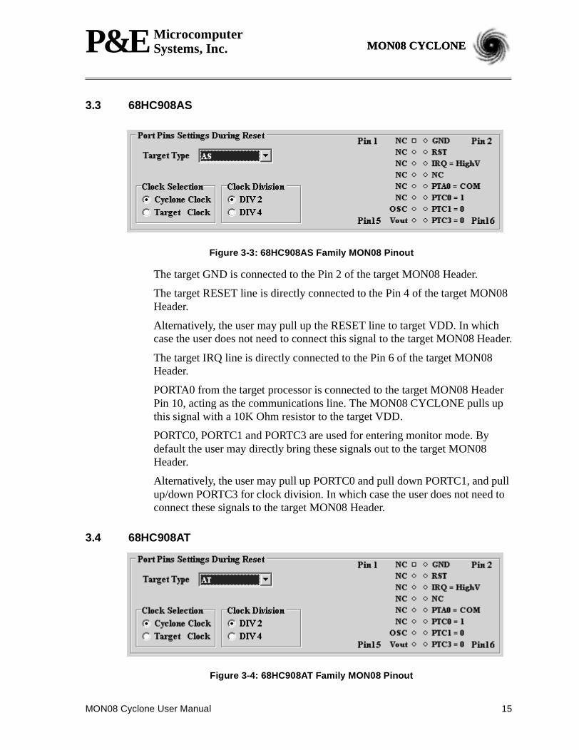
3.3 68HC908AS
Figure 3-3: 68HC908AS Family MON08 Pinout
The target GND is connected to the Pin 2 of the target MON08 Header.
The target RESET line is directly connected to the Pin 4 of the target MON08Header.
Alternatively, the user may pull up the RESET line to target VDD. In whichcase the user does not need to connect this signal to the target MON08 Header.
The target IRQ line is directly connected to the Pin 6 of the target MON08Header.
PORTA0 from the target processor is connected to the target MON08 HeaderPin 10, acting as the communications line. The MON08 CYCLONE pulls upthis signal with a 10K Ohm resistor to the target VDD.
PORTC0, PORTC1 and PORTC3 are used for entering monitor mode. Bydefault the user may directly bring these signals out to the target MON08Header.
Alternatively, the user may pull up PORTC0 and pull down PORTC1, and pullup/down PORTC3 for clock division. In which case the user does not need toconnect these signals to the target MON08 Header.
3.4 68HC908AT
Figure 3-4: 68HC908AT Family MON08 Pinout

16 MON08 Cyclone User Manual
P&E MicrocomputerSystems, Inc.MON08 CYCLONE
The target GND is connected to the Pin 2 of the target MON08 Header.
The target RESET line is directly connected to the Pin 4 of the target MON08Header.
Alternatively, the user may pull up the RESET line to target VDD. In whichcase the user does not need to connect this signal to the target MON08 Header.
The target IRQ line is directly connected to the Pin 6 of the target MON08Header.
PORTA0 from the target processor is connected to the target MON08 HeaderPin 10, acting as the communications line. The MON08 CYCLONE pulls upthis signal with a 10K Ohm resistor to the target VDD.
PORTC0, PORTC1 and PORTC3 are used for entering monitor mode. Bydefault the user may directly bring these signals out to the target MON08Header.
Alternatively, the user may pull up PORTC0 and pull down PORTC1, and pullup/down PORTC3 for clock division. In which case the user does not need toconnect these signals to the target MON08 Header.
3.5 68HC908AZ
Figure 3-5: 68HC908AZ Family MON08 Pinout
The target GND is connected to the Pin 2 of the target MON08 Header.
The target RESET line is directly connected to the Pin 4 of the target MON08Header.
Alternatively, the user may pull up the RESET line to target VDD. In whichcase the user does not need to connect this signal to the target MON08 Header.
The target IRQ line is directly connected to the Pin 6 of the target MON08Header.
PORTA0 from the target processor is connected to the target MON08 HeaderPin 10, acting as the communications line. The MON08 CYCLONE pulls upthis signal with a 10K Ohm resistor to the target VDD.
MON08 Cyclone User Manual 17
P&E MicrocomputerSystems, Inc. MON08 CYCLONEMON08 CYCLONE
PORTC0, PORTC1 and PORTC3 are used for entering monitor mode. Bydefault the user may directly bring these signals out to the target MON08Header.
Alternatively, the user may pull up PORTC0 and pull down PORTC1, and pullup/down PORTC3 for clock division. In which case the user does not need toconnect these signals to the target MON08 Header.
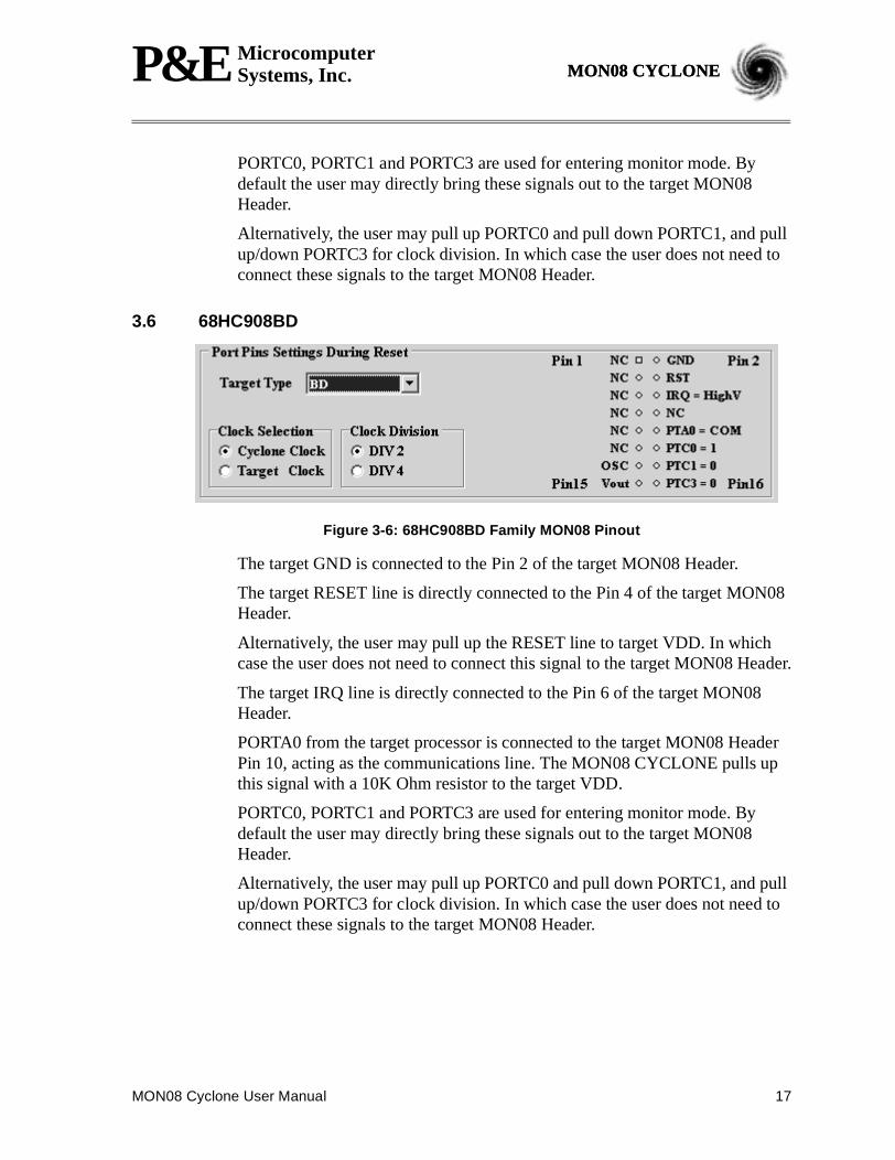
3.6 68HC908BD
Figure 3-6: 68HC908BD Family MON08 Pinout
The target GND is connected to the Pin 2 of the target MON08 Header.
The target RESET line is directly connected to the Pin 4 of the target MON08Header.
Alternatively, the user may pull up the RESET line to target VDD. In whichcase the user does not need to connect this signal to the target MON08 Header.
The target IRQ line is directly connected to the Pin 6 of the target MON08Header.
PORTA0 from the target processor is connected to the target MON08 HeaderPin 10, acting as the communications line. The MON08 CYCLONE pulls upthis signal with a 10K Ohm resistor to the target VDD.
PORTC0, PORTC1 and PORTC3 are used for entering monitor mode. Bydefault the user may directly bring these signals out to the target MON08Header.
Alternatively, the user may pull up PORTC0 and pull down PORTC1, and pullup/down PORTC3 for clock division. In which case the user does not need toconnect these signals to the target MON08 Header.
18 MON08 Cyclone User Manual
P&E MicrocomputerSystems, Inc.MON08 CYCLONE
3.7 68HC908EY
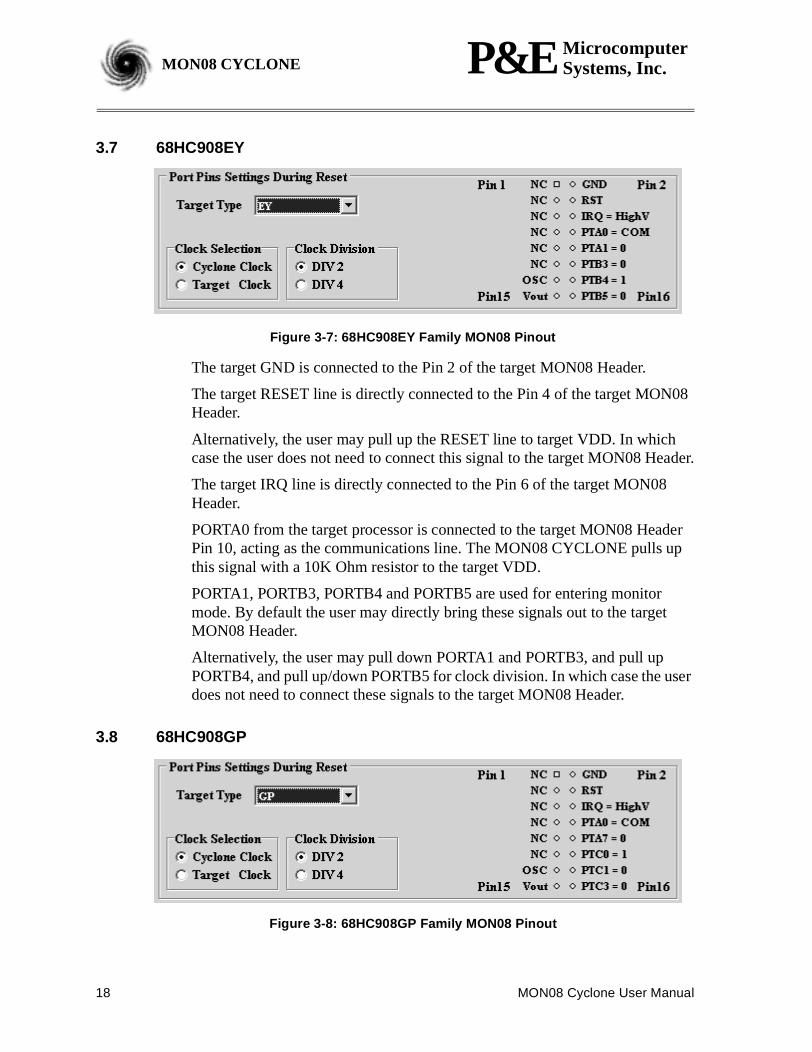
Figure 3-7: 68HC908EY Family MON08 Pinout
The target GND is connected to the Pin 2 of the target MON08 Header.
The target RESET line is directly connected to the Pin 4 of the target MON08Header.
Alternatively, the user may pull up the RESET line to target VDD. In whichcase the user does not need to connect this signal to the target MON08 Header.
The target IRQ line is directly connected to the Pin 6 of the target MON08Header.
PORTA0 from the target processor is connected to the target MON08 HeaderPin 10, acting as the communications line. The MON08 CYCLONE pulls upthis signal with a 10K Ohm resistor to the target VDD.
PORTA1, PORTB3, PORTB4 and PORTB5 are used for entering monitormode. By default the user may directly bring these signals out to the targetMON08 Header.
Alternatively, the user may pull down PORTA1 and PORTB3, and pull upPORTB4, and pull up/down PORTB5 for clock division. In which case the userdoes not need to connect these signals to the target MON08 Header.
3.8 68HC908GP
Figure 3-8: 68HC908GP Family MON08 Pinout

MON08 Cyclone User Manual 19
P&E MicrocomputerSystems, Inc. MON08 CYCLONEMON08 CYCLONE
The target GND is connected to the Pin 2 of the target MON08 Header.
The target RESET line is directly connected to the Pin 4 of the target MON08Header.
Alternatively, the user may pull up the RESET line to target VDD. In whichcase the user does not need to connect this signal to the target MON08 Header.
The target IRQ line is directly connected to the Pin 6 of the target MON08Header.
PORTA0 from the target processor is connected to the target MON08 HeaderPin 8, acting as the communications line. The MON08 CYCLONE pulls upthis signal with a 10K Ohm resistor to the target VDD.
PORTA7, PORTC0, PORTC1 and PORTC3 are used for entering monitormode. By default the user may directly bring these signals out to the targetMON08 Header.
Alternatively, the user may pull down PORTA7 and PORTC1, pull upPORTC0, and pull up/down PORTC3 for clock division. In which case the userdoes not need to connect these signals to the target MON08 Header.
3.9 68HC908GR16
Figure 3-9: 68HC908GR16 MON08 Pinout
The target GND is connected to the Pin 2 of the target MON08 Header.
The target RESET line is directly connected to the Pin 4 of the target MON08Header.
Alternatively, the user may pull up the RESET line to target VDD. In whichcase the user does not need to connect this signal to the target MON08 Header.
The target IRQ line is directly connected to the Pin 6 of the target MON08Header.
PORTA0 from the target processor is connected to the target MON08 HeaderPin 8, acting as the communications line. The MON08 CYCLONE pulls upthis signal with a 10K Ohm resistor to the target VDD.
20 MON08 Cyclone User Manual
P&E MicrocomputerSystems, Inc.MON08 CYCLONE
PORTA1, PORTB0, PORTB1 and PORTB4 are used for entering monitormode. By default the user may directly bring these signals out to the targetMON08 Header.
Alternatively, the user may pull up PORTB0, pull down PORTA1 andPORTB1, and pull up/down PORTB4 for clock division. In which case the userdoes not need to connect these signals to the target MON08 Header.
3.10 68HC908GR4/8
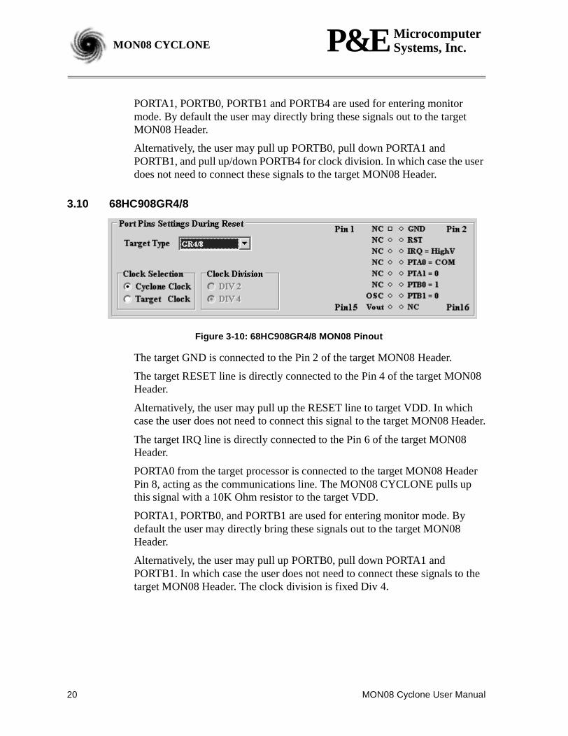
Figure 3-10: 68HC908GR4/8 MON08 Pinout
The target GND is connected to the Pin 2 of the target MON08 Header.
The target RESET line is directly connected to the Pin 4 of the target MON08Header.
Alternatively, the user may pull up the RESET line to target VDD. In whichcase the user does not need to connect this signal to the target MON08 Header.
The target IRQ line is directly connected to the Pin 6 of the target MON08Header.
PORTA0 from the target processor is connected to the target MON08 HeaderPin 8, acting as the communications line. The MON08 CYCLONE pulls upthis signal with a 10K Ohm resistor to the target VDD.
PORTA1, PORTB0, and PORTB1 are used for entering monitor mode. Bydefault the user may directly bring these signals out to the target MON08Header.
Alternatively, the user may pull up PORTB0, pull down PORTA1 andPORTB1. In which case the user does not need to connect these signals to thetarget MON08 Header. The clock division is fixed Div 4.
MON08 Cyclone User Manual 21
P&E MicrocomputerSystems, Inc. MON08 CYCLONEMON08 CYCLONE
3.11 68HC908GT
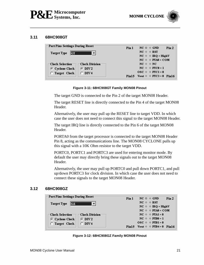
Figure 3-11: 68HC908GT Family MON08 Pinout
The target GND is connected to the Pin 2 of the target MON08 Header.
The target RESET line is directly connected to the Pin 4 of the target MON08Header.
Alternatively, the user may pull up the RESET line to target VDD. In whichcase the user does not need to connect this signal to the target MON08 Header.
The target IRQ line is directly connected to the Pin 6 of the target MON08Header.
PORTA0 from the target processor is connected to the target MON08 HeaderPin 8, acting as the communications line. The MON08 CYCLONE pulls upthis signal with a 10K Ohm resistor to the target VDD.
PORTC0, PORTC1 and PORTC3 are used for entering monitor mode. Bydefault the user may directly bring these signals out to the target MON08Header.
Alternatively, the user may pull up PORTC0 and pull down PORTC1, and pullup/down PORTC3 for clock division. In which case the user does not need toconnect these signals to the target MON08 Header.
3.12 68HC908GZ
Figure 3-12: 68HC908GZ Family MON08 Pinout
22 MON08 Cyclone User Manual
P&E MicrocomputerSystems, Inc.MON08 CYCLONE
The target GND is connected to the Pin 2 of the target MON08 Header.
The target RESET line is directly connected to the Pin 4 of the target MON08Header.
Alternatively, the user may pull up the RESET line to target VDD. In whichcase the user does not need to connect this signal to the target MON08 Header.
The target IRQ line is directly connected to the Pin 6 of the target MON08Header.
PORTA0 from the target processor is connected to the target MON08 HeaderPin 8, acting as the communications line. The MON08 CYCLONE pulls upthis signal with a 10K Ohm resistor to the target VDD.
PORTA1, PORTB0, PORTB1 and PORTB4 are used for entering monitormode. By default the user may directly bring these signals out to the targetMON08 Header.
Alternatively, the user may pull up PORTB0, pull down PORTA1 andPORTB1, and pull up/down PORTB4 for clock division. In which case the userdoes not need to connect these signals to the target MON08 Header.
3.13 68HC908JB1/8
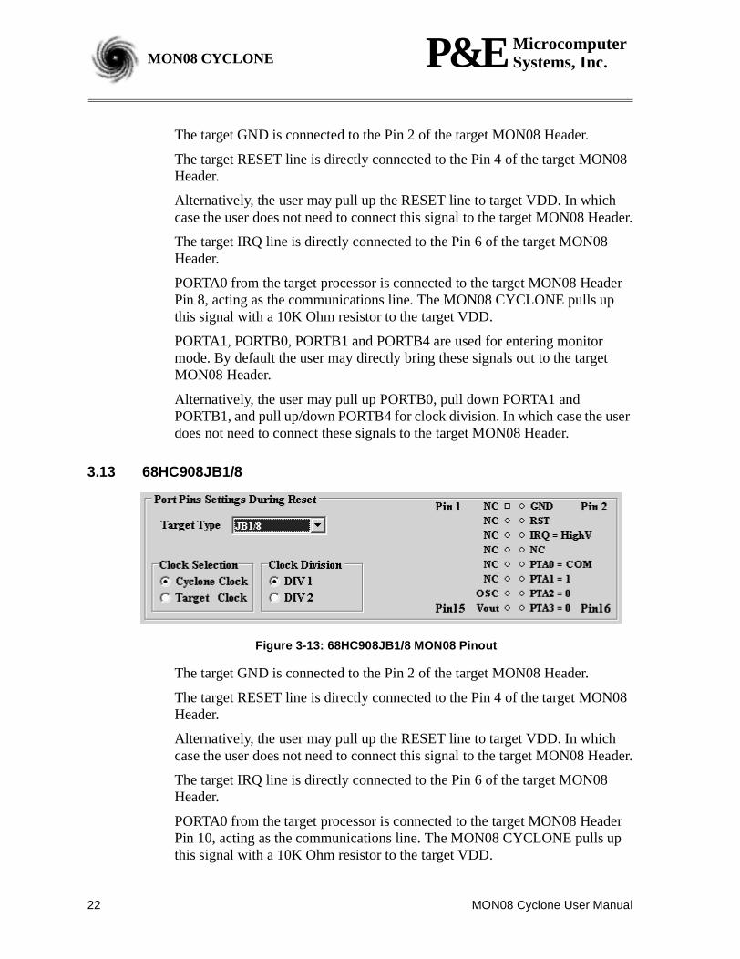
Figure 3-13: 68HC908JB1/8 MON08 Pinout
The target GND is connected to the Pin 2 of the target MON08 Header.
The target RESET line is directly connected to the Pin 4 of the target MON08Header.
Alternatively, the user may pull up the RESET line to target VDD. In whichcase the user does not need to connect this signal to the target MON08 Header.
The target IRQ line is directly connected to the Pin 6 of the target MON08Header.
PORTA0 from the target processor is connected to the target MON08 HeaderPin 10, acting as the communications line. The MON08 CYCLONE pulls upthis signal with a 10K Ohm resistor to the target VDD.
MON08 Cyclone User Manual 23
P&E MicrocomputerSystems, Inc. MON08 CYCLONEMON08 CYCLONE
PORTA1, PORTA2 and PORTA3 are used for entering monitor mode. Bydefault the user may directly bring these signals out to the target MON08Header.
Alternatively, the user may pull up PORTA1 and pull down PORTA2, and pullup/down PORTA3 for clock division. In which case the user does not need toconnect these signals to the target MON08 Header.
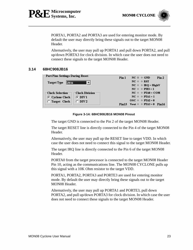
3.14 68HC908JB16
Figure 3-14: 68HC908JB16 MON08 Pinout
The target GND is connected to the Pin 2 of the target MON08 Header.
The target RESET line is directly connected to the Pin 4 of the target MON08Header.
Alternatively, the user may pull up the RESET line to target VDD. In whichcase the user does not need to connect this signal to the target MON08 Header.
The target IRQ line is directly connected to the Pin 6 of the target MON08Header.
PORTA0 from the target processor is connected to the target MON08 HeaderPin 10, acting as the communications line. The MON08 CYCLONE pulls upthis signal with a 10K Ohm resistor to the target VDD.
PORTA1, PORTA2, PORTA3 and PORTE3 are used for entering monitormode. By default the user may directly bring these signals out to the targetMON08 Header.
Alternatively, the user may pull up PORTA1 and PORTE3, pull downPORTA2, and pull up/down PORTA3 for clock division. In which case the userdoes not need to connect these signals to the target MON08 Header.
24 MON08 Cyclone User Manual
P&E MicrocomputerSystems, Inc.MON08 CYCLONE
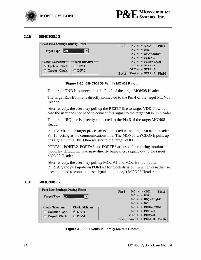
3.15 68HC908JG
Figure 3-15: 68HC908JG Family MON08 Pinout
The target GND is connected to the Pin 2 of the target MON08 Header.
The target RESET line is directly connected to the Pin 4 of the target MON08Header.
Alternatively, the user may pull up the RESET line to target VDD. In whichcase the user does not need to connect this signal to the target MON08 Header.
The target IRQ line is directly connected to the Pin 6 of the target MON08Header.
PORTA0 from the target processor is connected to the target MON08 HeaderPin 10, acting as the communications line. The MON08 CYCLONE pulls upthis signal with a 10K Ohm resistor to the target VDD.
PORTA1, PORTA2, PORTA3 and PORTE3 are used for entering monitormode. By default the user may directly bring these signals out to the targetMON08 Header.
Alternatively, the user may pull up PORTA1 and PORTE3, pull downPORTA2, and pull up/down PORTA3 for clock division. In which case the userdoes not need to connect these signals to the target MON08 Header.
3.16 68HC908JK
Figure 3-16: 68HC908JK Family MON08 Pinout
MON08 Cyclone User Manual 25
P&E MicrocomputerSystems, Inc. MON08 CYCLONEMON08 CYCLONE
The target GND is connected to the Pin 2 of the target MON08 Header.
The target RESET line is directly connected to the Pin 4 of the target MON08Header.
Alternatively, the user may pull up the RESET line to target VDD. In whichcase the user does not need to connect this signal to the target MON08 Header.
The target IRQ line is directly connected to the Pin 6 of the target MON08Header.
PORTB0 from the target processor is connected to the target MON08 HeaderPin 10, acting as the communications line. The MON08 CYCLONE pulls upthis signal with a 10K Ohm resistor to the target VDD.
PORTB1, PORTB2 and PORTB3 are used for entering monitor mode. Bydefault the user may directly bring these signals out to the target MON08Header.
Alternatively, the user may pull up PORTB1 and pull down PORTB2, and pullup/down PORTB3 for clock division. In which case the user does not need toconnect these signals to the target MON08 Header.
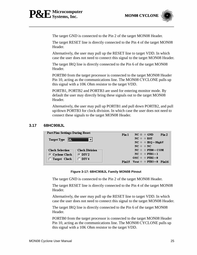
3.17 68HC908JL
Figure 3-17: 68HC908JL Family MON08 Pinout
The target GND is connected to the Pin 2 of the target MON08 Header.
The target RESET line is directly connected to the Pin 4 of the target MON08Header.
Alternatively, the user may pull up the RESET line to target VDD. In whichcase the user does not need to connect this signal to the target MON08 Header.
The target IRQ line is directly connected to the Pin 6 of the target MON08Header.
PORTB0 from the target processor is connected to the target MON08 HeaderPin 10, acting as the communications line. The MON08 CYCLONE pulls upthis signal with a 10K Ohm resistor to the target VDD.

26 MON08 Cyclone User Manual
P&E MicrocomputerSystems, Inc.MON08 CYCLONE
PORTB1, PORTB2 and PORTB3 are used for entering monitor mode. Bydefault the user may directly bring these signals out to the target MON08Header.
Alternatively, the user may pull up PORTB1 and pull down PORTB2, and pullup/down PORTB3 for clock division. In which case the user does not need toconnect these signals to the target MON08 Header.
3.18 68HC908KX
Figure 3-18: 68HC908KX Family MON08 Pinout
The target GND is connected to the Pin 2 of the target MON08 Header.
The user must pull up the RESET line to target VDD with an external resistor.
The target IRQ line is directly connected to the Pin 6 of the target MON08Header.
PORTA0 from the target processor is connected to the target MON08 HeaderPin 8, acting as the communications line. The MON08 CYCLONE pulls upthis signal with a 10K Ohm resistor to the target VDD.
PORTA1, PORTB0 and PORTB1 are used for entering monitor mode. Bydefault the user may directly bring these signals out to the target MON08Header.
Alternatively, the user may pull up PORTB0 and pull down PORTA1 andPORTB1. In which case the user does not need to connect these signals to thetarget MON08 Header. The clock division is fixed Div 4.
MON08 Cyclone User Manual 27
P&E MicrocomputerSystems, Inc. MON08 CYCLONEMON08 CYCLONE
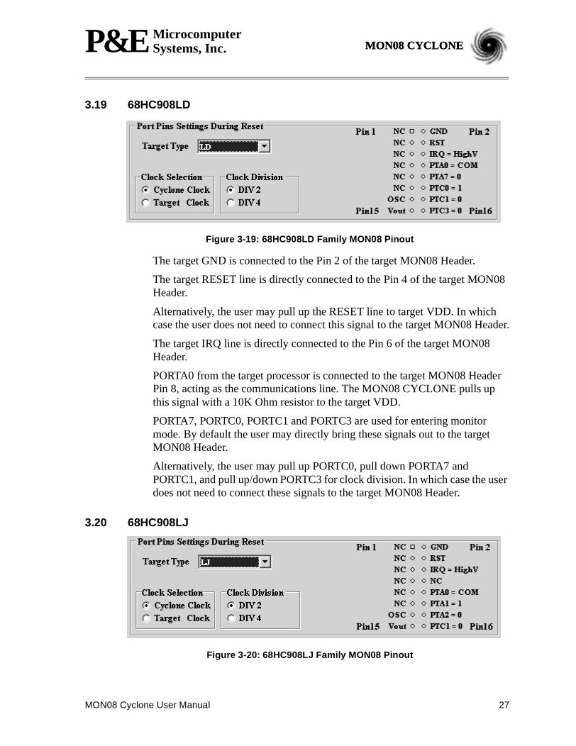
3.19 68HC908LD
Figure 3-19: 68HC908LD Family MON08 Pinout
The target GND is connected to the Pin 2 of the target MON08 Header.
The target RESET line is directly connected to the Pin 4 of the target MON08Header.
Alternatively, the user may pull up the RESET line to target VDD. In whichcase the user does not need to connect this signal to the target MON08 Header.
The target IRQ line is directly connected to the Pin 6 of the target MON08Header.
PORTA0 from the target processor is connected to the target MON08 HeaderPin 8, acting as the communications line. The MON08 CYCLONE pulls upthis signal with a 10K Ohm resistor to the target VDD.
PORTA7, PORTC0, PORTC1 and PORTC3 are used for entering monitormode. By default the user may directly bring these signals out to the targetMON08 Header.
Alternatively, the user may pull up PORTC0, pull down PORTA7 andPORTC1, and pull up/down PORTC3 for clock division. In which case the userdoes not need to connect these signals to the target MON08 Header.
3.20 68HC908LJ
Figure 3-20: 68HC908LJ Family MON08 Pinout
28 MON08 Cyclone User Manual
P&E MicrocomputerSystems, Inc.MON08 CYCLONE
The target GND is connected to the Pin 2 of the target MON08 Header.
The target RESET line is directly connected to the Pin 4 of the target MON08Header.
Alternatively, the user may pull up the RESET line to target VDD. In whichcase the user does not need to connect this signal to the target MON08 Header.
The target IRQ line is directly connected to the Pin 6 of the target MON08Header.
PORTA0 from the target processor is connected to the target MON08 HeaderPin 10, acting as the communications line. The MON08 CYCLONE pulls upthis signal with a 10K Ohm resistor to the target VDD.
PORTA1, PORTA2 and PORTC1 are used for entering monitor mode. Bydefault the user may directly bring these signals out to the target MON08Header.
Alternatively, the user may pull up PORTA1 and pull down PORTA2, and pullup/down PORTC1 for clock division. In which case the user does not need toconnect these signals to the target MON08 Header.
3.21 68HC908MR16/32
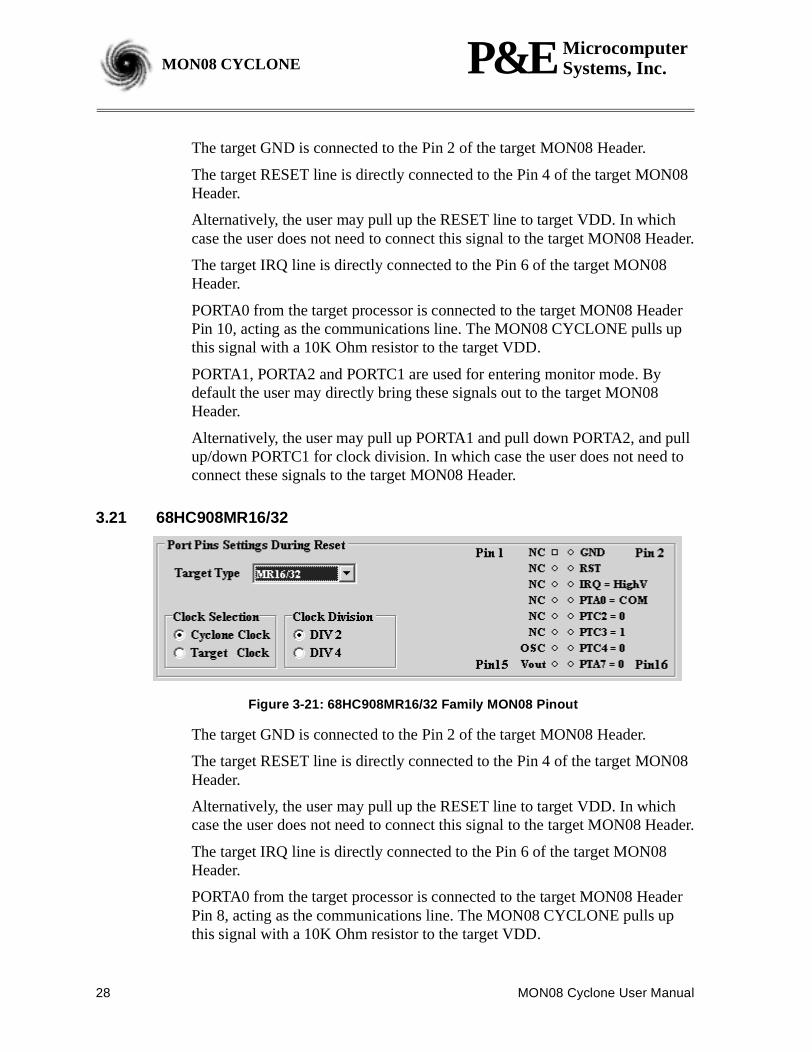
Figure 3-21: 68HC908MR16/32 Family MON08 Pinout
The target GND is connected to the Pin 2 of the target MON08 Header.
The target RESET line is directly connected to the Pin 4 of the target MON08Header.
Alternatively, the user may pull up the RESET line to target VDD. In whichcase the user does not need to connect this signal to the target MON08 Header.
The target IRQ line is directly connected to the Pin 6 of the target MON08Header.
PORTA0 from the target processor is connected to the target MON08 HeaderPin 8, acting as the communications line. The MON08 CYCLONE pulls upthis signal with a 10K Ohm resistor to the target VDD.
MON08 Cyclone User Manual 29
P&E MicrocomputerSystems, Inc. MON08 CYCLONEMON08 CYCLONE
PORTA7, PORTC2, PORTC3 and PORTC4 are used for entering monitormode. By default the user may directly bring these signals out to the targetMON08 Header.
Alternatively, the user may pull up PORTC3, pull down PORTA7 andPORTC4, and pull up/down PORTC2 for clock division. In which case the userdoes not need to connect these signals to the target MON08 Header.
Please note that the MR4/8 is not supported by the MON08 CYCLONE.However, the MON08 MULTILINK by P&E does. Please refer to the MON08MULTILINK user’s manual for detailed information.
3.22 68HC908QT
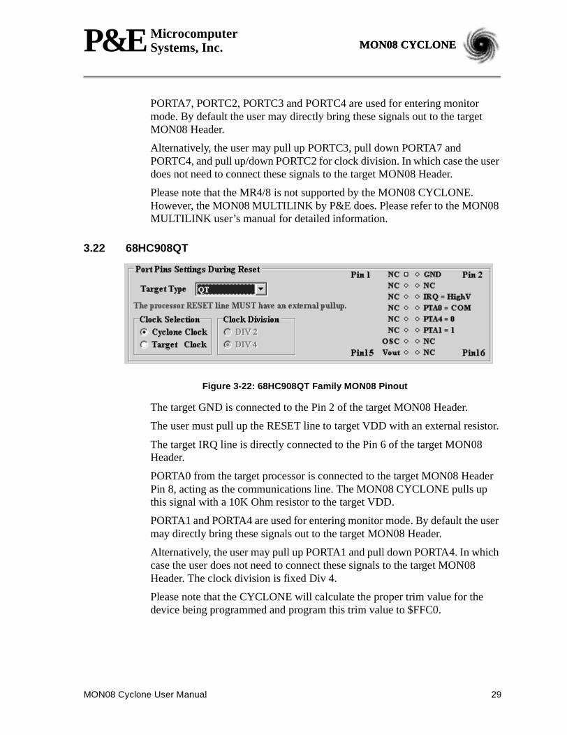
Figure 3-22: 68HC908QT Family MON08 Pinout
The target GND is connected to the Pin 2 of the target MON08 Header.
The user must pull up the RESET line to target VDD with an external resistor.
The target IRQ line is directly connected to the Pin 6 of the target MON08Header.
PORTA0 from the target processor is connected to the target MON08 HeaderPin 8, acting as the communications line. The MON08 CYCLONE pulls upthis signal with a 10K Ohm resistor to the target VDD.
PORTA1 and PORTA4 are used for entering monitor mode. By default the usermay directly bring these signals out to the target MON08 Header.
Alternatively, the user may pull up PORTA1 and pull down PORTA4. In whichcase the user does not need to connect these signals to the target MON08Header. The clock division is fixed Div 4.
Please note that the CYCLONE will calculate the proper trim value for thedevice being programmed and program this trim value to $FFC0.
30 MON08 Cyclone User Manual
P&E MicrocomputerSystems, Inc.MON08 CYCLONE
3.23 68HC908QY
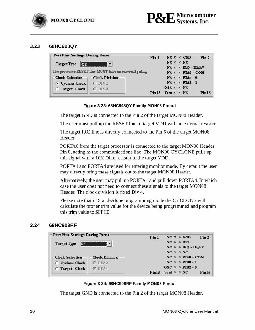
Figure 3-23: 68HC908QY Family MON08 Pinout
The target GND is connected to the Pin 2 of the target MON08 Header.
The user must pull up the RESET line to target VDD with an external resistor.
The target IRQ line is directly connected to the Pin 6 of the target MON08Header.
PORTA0 from the target processor is connected to the target MON08 HeaderPin 8, acting as the communications line. The MON08 CYCLONE pulls upthis signal with a 10K Ohm resistor to the target VDD.
PORTA1 and PORTA4 are used for entering monitor mode. By default the usermay directly bring these signals out to the target MON08 Header.
Alternatively, the user may pull up PORTA1 and pull down PORTA4. In whichcase the user does not need to connect these signals to the target MON08Header. The clock division is fixed Div 4.
Please note that in Stand-Alone programming mode the CYCLONE willcalculate the proper trim value for the device being programmed and programthis trim value to $FFC0.
3.24 68HC908RF
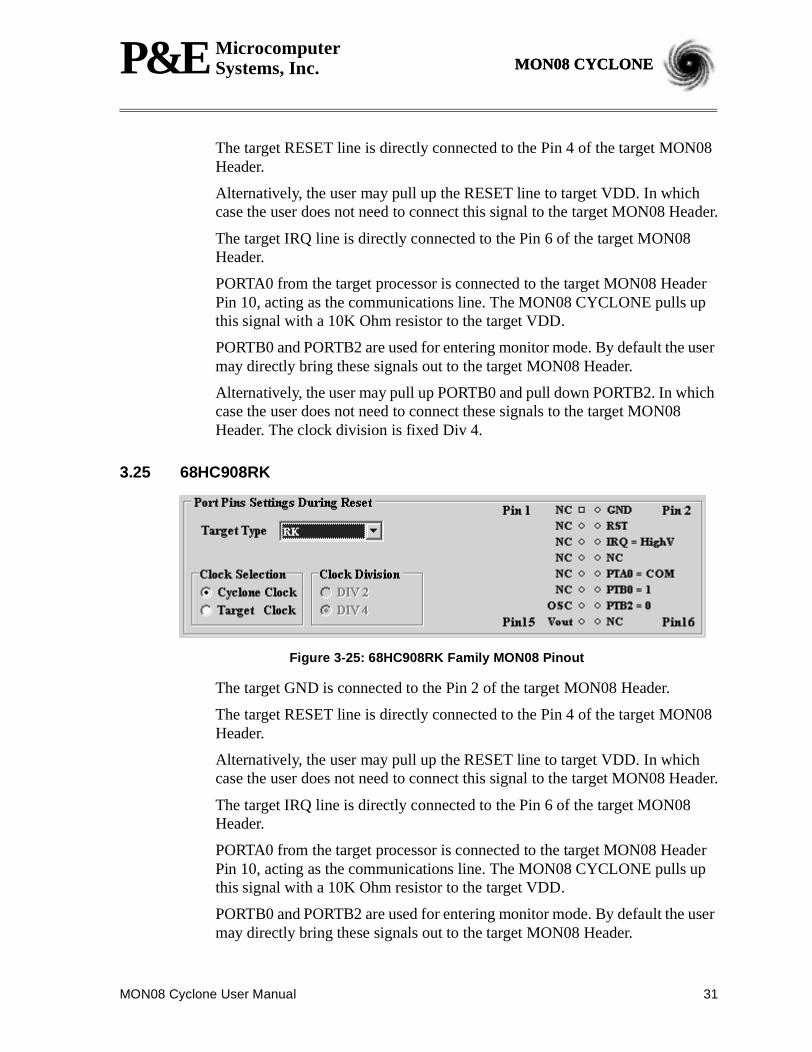
Figure 3-24: 68HC908RF Family MON08 Pinout
The target GND is connected to the Pin 2 of the target MON08 Header.
MON08 Cyclone User Manual 31
P&E MicrocomputerSystems, Inc. MON08 CYCLONEMON08 CYCLONE
The target RESET line is directly connected to the Pin 4 of the target MON08Header.
Alternatively, the user may pull up the RESET line to target VDD. In whichcase the user does not need to connect this signal to the target MON08 Header.
The target IRQ line is directly connected to the Pin 6 of the target MON08Header.
PORTA0 from the target processor is connected to the target MON08 HeaderPin 10, acting as the communications line. The MON08 CYCLONE pulls upthis signal with a 10K Ohm resistor to the target VDD.
PORTB0 and PORTB2 are used for entering monitor mode. By default the usermay directly bring these signals out to the target MON08 Header.
Alternatively, the user may pull up PORTB0 and pull down PORTB2. In whichcase the user does not need to connect these signals to the target MON08Header. The clock division is fixed Div 4.
3.25 68HC908RK
Figure 3-25: 68HC908RK Family MON08 Pinout
The target GND is connected to the Pin 2 of the target MON08 Header.
The target RESET line is directly connected to the Pin 4 of the target MON08Header.
Alternatively, the user may pull up the RESET line to target VDD. In whichcase the user does not need to connect this signal to the target MON08 Header.
The target IRQ line is directly connected to the Pin 6 of the target MON08Header.
PORTA0 from the target processor is connected to the target MON08 HeaderPin 10, acting as the communications line. The MON08 CYCLONE pulls upthis signal with a 10K Ohm resistor to the target VDD.
PORTB0 and PORTB2 are used for entering monitor mode. By default the usermay directly bring these signals out to the target MON08 Header.
32 MON08 Cyclone User Manual
P&E MicrocomputerSystems, Inc.MON08 CYCLONE
Alternatively, the user may pull up PORTB0 and pull down PORTB2. In whichcase the user does not need to connect these signals to the target MON08Header. The clock division is fixed Div 4.
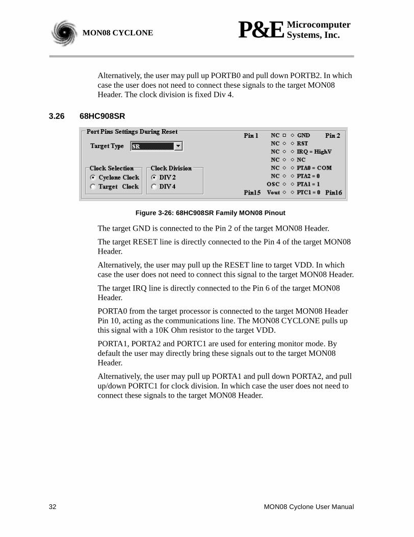
3.26 68HC908SR
Figure 3-26: 68HC908SR Family MON08 Pinout
The target GND is connected to the Pin 2 of the target MON08 Header.
The target RESET line is directly connected to the Pin 4 of the target MON08Header.
Alternatively, the user may pull up the RESET line to target VDD. In whichcase the user does not need to connect this signal to the target MON08 Header.
The target IRQ line is directly connected to the Pin 6 of the target MON08Header.
PORTA0 from the target processor is connected to the target MON08 HeaderPin 10, acting as the communications line. The MON08 CYCLONE pulls upthis signal with a 10K Ohm resistor to the target VDD.
PORTA1, PORTA2 and PORTC1 are used for entering monitor mode. Bydefault the user may directly bring these signals out to the target MON08Header.
Alternatively, the user may pull up PORTA1 and pull down PORTA2, and pullup/down PORTC1 for clock division. In which case the user does not need toconnect these signals to the target MON08 Header.
MON08 Cyclone User Manual 33
P&E MicrocomputerSystems, Inc. MON08 CYCLONEMON08 CYCLONE
4 STAND-ALONE PROGRAMMER OPERATIONThe MON08 CYCLONE may serve as a Stand-Alone Programmer for68HC908 targets. In this configuration, a PC is first needed to configure theCYCLONE for a specific target processor. After this the CYCLONE mayfunction independently.
The target power management schemes remain the same.
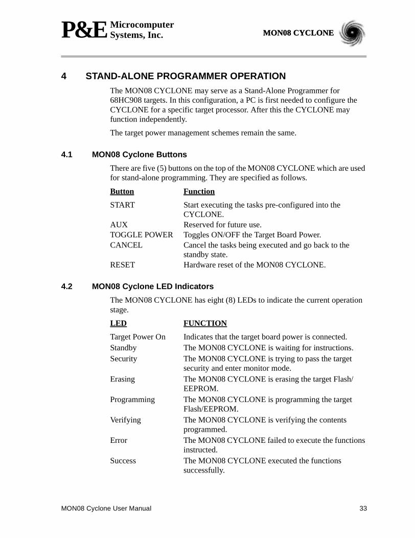
4.1 MON08 Cyclone Buttons
There are five (5) buttons on the top of the MON08 CYCLONE which are usedfor stand-alone programming. They are specified as follows.
Button Function
START Start executing the tasks pre-configured into theCYCLONE.
AUX Reserved for future use.TOGGLE POWER Toggles ON/OFF the Target Board Power.CANCEL Cancel the tasks being executed and go back to the
standby state.RESET Hardware reset of the MON08 CYCLONE.
4.2 MON08 Cyclone LED Indicators
The MON08 CYCLONE has eight (8) LEDs to indicate the current operationstage.
LED FUNCTION
Target Power On Indicates that the target board power is connected.Standby The MON08 CYCLONE is waiting for instructions.Security The MON08 CYCLONE is trying to pass the target
security and enter monitor mode.Erasing The MON08 CYCLONE is erasing the target Flash/
EEPROM.Programming The MON08 CYCLONE is programming the target
Flash/EEPROM.Verifying The MON08 CYCLONE is verifying the contents
programmed.Error The MON08 CYCLONE failed to execute the functions
instructed.Success The MON08 CYCLONE executed the functions
successfully.

34 MON08 Cyclone User Manual
P&E MicrocomputerSystems, Inc.MON08 CYCLONE
4.3 Example
When the MON08 CYCLONE is powered up, both the Target Power On andStandby LED are turned on. These LEDs are only valid in stand-alone mode.After the user programs the contents and procedures into the CYCLONE on-board flash, the CYCLONE may be used as a Stand-Alone Programmer.Suppose the user wants to perform the following instructions for a 68HC908target:
1) Erase Module2) Blank Check Module3) Program Module4) Verify Module.
When the Start Button is pressed, the “Target Power On” LED will turn off andcome back on again, indicating that the MON08 Cyclone is powering down,and then powering up, the target board.
Then the Standby LED will turn off and the Security LED will turn on. Here, ifthe target flash needs to be erased first to bypass the security, the Security LEDwill turn off and the Erasing LED will turn on.
When the Erasing LED turns off, the CYCLONE attempts to pass securityagain.
Then, when the CYCLONE starts programming the module, the“Programming” LED is illuminated.
After this is done, the “Programming” LED is turned off and the “Verifying”LED is turned on, designating that the CYCLONE is verifying the contents justprogrammed into the target.
Finally, if these operations have been performed successfully, the “Success”LED and the “Standby” LED are illuminated. One stand-alone programmingcycle has just been completed.
MON08 Cyclone User Manual 35
P&E MicrocomputerSystems, Inc. MON08 CYCLONEMON08 CYCLONE
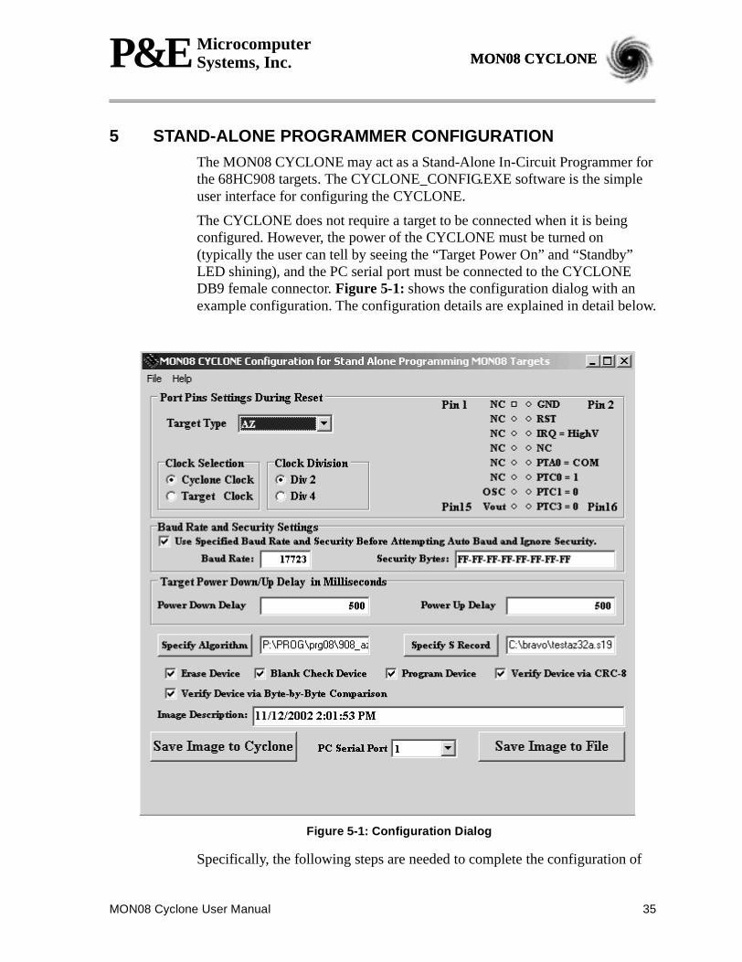
5 STAND-ALONE PROGRAMMER CONFIGURATIONThe MON08 CYCLONE may act as a Stand-Alone In-Circuit Programmer forthe 68HC908 targets. The CYCLONE_CONFIG.EXE software is the simpleuser interface for configuring the CYCLONE.
The CYCLONE does not require a target to be connected when it is beingconfigured. However, the power of the CYCLONE must be turned on(typically the user can tell by seeing the “Target Power On” and “Standby”LED shining), and the PC serial port must be connected to the CYCLONEDB9 female connector.Figure 5-1: shows the configuration dialog with anexample configuration. The configuration details are explained in detail below.
Figure 5-1: Configuration Dialog
Specifically, the following steps are needed to complete the configuration of
36 MON08 Cyclone User Manual
P&E MicrocomputerSystems, Inc.MON08 CYCLONE
the CYCLONE for Stand Alone Programming.
5.1 Command Line Parameters
There are two command line parameters of interest. One is thev parameter,which will ignore the object file S-record address range check. The other is the? parameter, which allows the CYCLONE configuration status window stayafter its operation. This enables you to take a look at the procedure and see thateverything is OK, or, for you to find out at which step it is experiencingdifficulties.
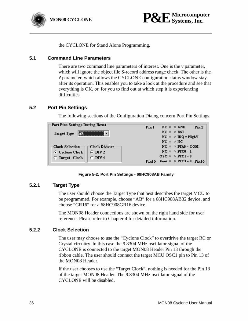
5.2 Port Pin Settings
The following sections of the Configuration Dialog concern Port Pin Settings.
Figure 5-2: Port Pin Settings - 68HC908AB Family
5.2.1 Target Type
The user should choose the Target Type that best describes the target MCU tobe programmed. For example, choose “AB” for a 68HC908AB32 device, andchoose “GR16” for a 68HC908GR16 device.
The MON08 Header connections are shown on the right hand side for userreference. Please refer to Chapter 4 for detailed information.
5.2.2 Clock Selection
The user may choose to use the “Cyclone Clock” to overdrive the target RC orCrystal circuitry. In this case the 9.8304 MHz oscillator signal of theCYCLONE is connected to the target MON08 Header Pin 13 through theribbon cable. The user should connect the target MCU OSC1 pin to Pin 13 ofthe MON08 Header.
If the user chooses to use the “Target Clock”, nothing is needed for the Pin 13of the target MON08 Header. The 9.8304 MHz oscillator signal of theCYCLONE will be disabled.
MON08 Cyclone User Manual 37
P&E MicrocomputerSystems, Inc. MON08 CYCLONEMON08 CYCLONE
5.2.3 Clock Division
The user may freely choose the clock division (if the target supports) as long asthe target bus frequency stays within specification. If the port pin thatdetermines the clock division is not connected to the target MON08 Header,the user can safely ignore this selection.
Typically the clock division does not affect the communications between theMON08 CYCLONE and the target. Normally a smaller clock division leads tofaster target bus frequencies, and faster communications between the MON08CYCLONE and the target, which in turn leads to a shorter programming time.
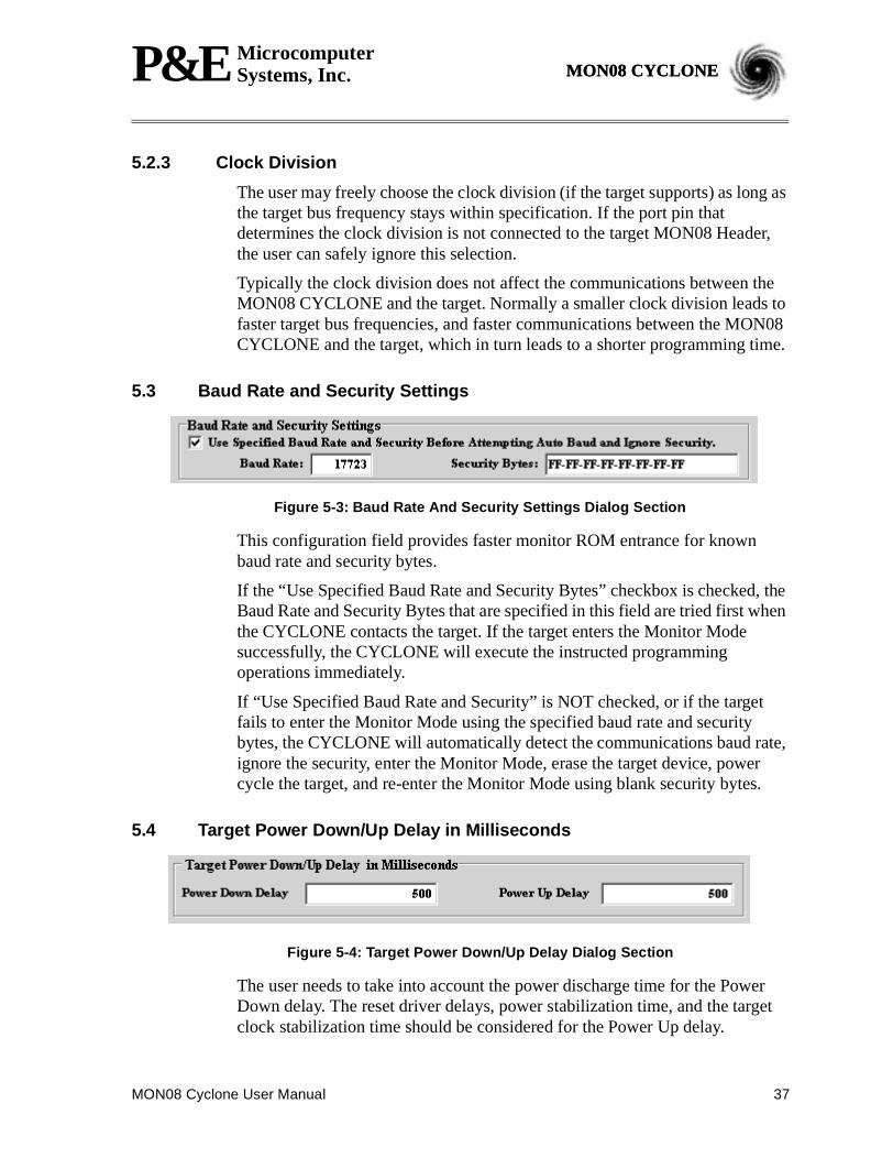
5.3 Baud Rate and Security Settings
Figure 5-3: Baud Rate And Security Settings Dialog Section
This configuration field provides faster monitor ROM entrance for knownbaud rate and security bytes.
If the “Use Specified Baud Rate and Security Bytes” checkbox is checked, theBaud Rate and Security Bytes that are specified in this field are tried first whenthe CYCLONE contacts the target. If the target enters the Monitor Modesuccessfully, the CYCLONE will execute the instructed programmingoperations immediately.
If “Use Specified Baud Rate and Security” is NOT checked, or if the targetfails to enter the Monitor Mode using the specified baud rate and securitybytes, the CYCLONE will automatically detect the communications baud rate,ignore the security, enter the Monitor Mode, erase the target device, powercycle the target, and re-enter the Monitor Mode using blank security bytes.
5.4 Target Power Down/Up Delay in Milliseconds
Figure 5-4: Target Power Down/Up Delay Dialog Section
The user needs to take into account the power discharge time for the PowerDown delay. The reset driver delays, power stabilization time, and the targetclock stabilization time should be considered for the Power Up delay.
38 MON08 Cyclone User Manual
P&E MicrocomputerSystems, Inc.MON08 CYCLONE
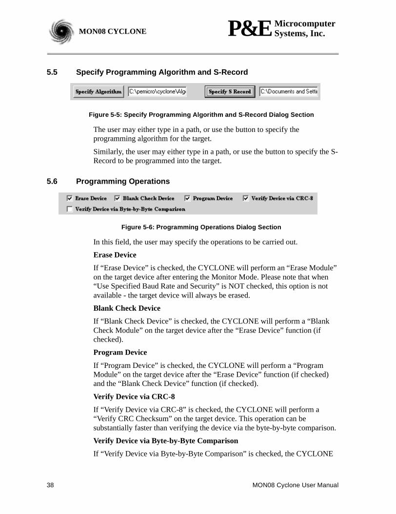
5.5 Specify Programming Algorithm and S-Record
Figure 5-5: Specify Programming Algorithm and S-Record Dialog Section
The user may either type in a path, or use the button to specify theprogramming algorithm for the target.
Similarly, the user may either type in a path, or use the button to specify the S-Record to be programmed into the target.
5.6 Programming Operations
Figure 5-6: Programming Operations Dialog Section
In this field, the user may specify the operations to be carried out.
Erase Device
If “Erase Device” is checked, the CYCLONE will perform an “Erase Module”on the target device after entering the Monitor Mode. Please note that when“Use Specified Baud Rate and Security” is NOT checked, this option is notavailable - the target device will always be erased.
Blank Check Device
If “Blank Check Device” is checked, the CYCLONE will perform a “BlankCheck Module” on the target device after the “Erase Device” function (ifchecked).
Program Device
If “Program Device” is checked, the CYCLONE will perform a “ProgramModule” on the target device after the “Erase Device” function (if checked)and the “Blank Check Device” function (if checked).
Verify Device via CRC-8
If “Verify Device via CRC-8” is checked, the CYCLONE will perform a“Verify CRC Checksum” on the target device. This operation can besubstantially faster than verifying the device via the byte-by-byte comparison.
Verify Device via Byte-by-Byte Comparison
If “Verify Device via Byte-by-Byte Comparison” is checked, the CYCLONE

MON08 Cyclone User Manual 39
P&E MicrocomputerSystems, Inc. MON08 CYCLONEMON08 CYCLONE
will perform a “Verify Module” on the target device. Every byte of the targetmemory to be verified is read and compared with the contents within theCYCLONE.
5.7 Image Description
The CYCLONE Configuration Utility allows the user to summarize thepurpose of current configuration for future reference. The description will beeither programmed into the CYCLONE or saved into a file (encrypted).
This field will not affect the CYCLONE operations with the target.
5.8 Save Image
“Save Image to Cyclone” allows the current configuration to be programmedinto the CYCLONE. The CYCLONE will then be ready for operations.
The “PC Serial Port” specifies which COM port the PC uses to communicatewith the CYCLONE to program the configurations.
“Save Image to File” allows the user to save the configuration into a file, whichmay be used for future reference, e.g., comparing the CYCLONE contentswith the file to see if they are the same.
5.9 Stand-Alone Operation Procedure
The following steps must be followed in order for the CYCLONE to operateproperly:
1. Turn off the target power supply if the “POWER IN” Jack is adopted.
2. Turn off the MON08 CYCLONE board power.
3. Set the correct Jumper settings.
3.1 Choose the target voltage (Jumper 1 for 5V targets or Jumper 2for 3.3V targets).
3.2 If applicable, set the Jumpers 3, 4, and 5 to obtain target powerfrom the MON08 CYCLONE.
4. Connect the target power supply to the “POWER IN” Jack, if applica-ble.
5. Connect the “POWER OUT” Jack to the target board power, if applica-ble.
6. Connect the MON08 Header Ribbon Cable to the target MON08 port.
7. Turn on the MON08 CYCLONE board power.
8. Turn on the target power supply, if applicable.
40 MON08 Cyclone User Manual
P&E MicrocomputerSystems, Inc.MON08 CYCLONE
9. Press the “START” push button on the CYCLONE. You will see theLEDs light up as specific functions are being executed.
When the “Success” LED lights up, you have successfully programmed yourtarget.
6 PC-HOSTED DEBUG/PROGRAMMING SOFTWAREFree or low-cost software options for interactively programming anddebugging 68HC08 MCUs from the PC are available from P&EMicrocomputer Systems (www.pemicro.com) and Metrowerks(www.metrowerks.com). P&E’s ICS08 interface software packages areavailable at no charge from their web site. Metrowerks’ CodeWarriorDevelopment Studio for 68HC08, Special Edition, is available at no chargefrom the Motorola MCU Web site (www.motorola.com/semiconductors/mcu).You must register for the license key for this software.
Note: The user should make sure they have the most recent version of thesesoftware kits. The latest updates can be downloaded from the web pages listedin Section 6.1.1 Latest Updates - P&E SoftwareandSection 6.2.1 LatestUpdates - Metrowerks Software.
6.1 P&E Microcomputer Systems Software
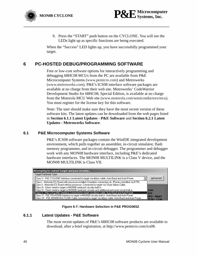
P&E’s ICS08 software packages contain the WinIDE integrated developmentenvironment, which pulls together an assembler, in-circuit simulator, flashmemory programmer, and in-circuit debugger. The programmer and debuggerwork with any MON08 hardware interface, including P&E’s dedicatedhardware interfaces. The MON08 MULTILINK is a Class V device, and theMON08 MULTILINK is Class VII.
Figure 6-7: Hardware Selection in P&E PROG08SZ
6.1.1 Latest Updates - P&E Software
The most recent updates of P&E’s 68HC08 software products are available todownload, after a brief registration, at http://www.pemicro.com/ics08.
MON08 Cyclone User Manual 41
P&E MicrocomputerSystems, Inc. MON08 CYCLONEMON08 CYCLONE
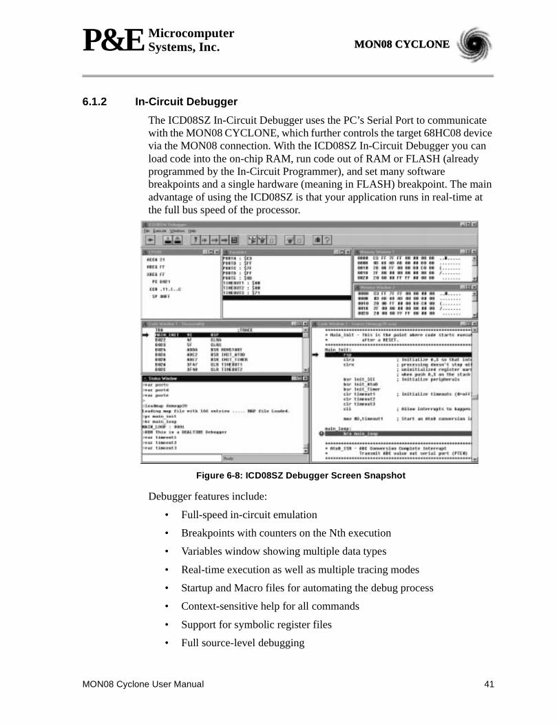
6.1.2 In-Circuit Debugger
The ICD08SZ In-Circuit Debugger uses the PC’s Serial Port to communicatewith the MON08 CYCLONE, which further controls the target 68HC08 devicevia the MON08 connection. With the ICD08SZ In-Circuit Debugger you canload code into the on-chip RAM, run code out of RAM or FLASH (alreadyprogrammed by the In-Circuit Programmer), and set many softwarebreakpoints and a single hardware (meaning in FLASH) breakpoint. The mainadvantage of using the ICD08SZ is that your application runs in real-time atthe full bus speed of the processor.
Figure 6-8: ICD08SZ Debugger Screen Snapshot
Debugger features include:
• Full-speed in-circuit emulation
• Breakpoints with counters on the Nth execution
• Variables window showing multiple data types
• Real-time execution as well as multiple tracing modes
• Startup and Macro files for automating the debug process
• Context-sensitive help for all commands
• Support for symbolic register files
• Full source-level debugging
42 MON08 Cyclone User Manual
P&E MicrocomputerSystems, Inc.MON08 CYCLONE
When connecting to the target, the user will be prompted to make selectionsfrom the Target Connection And Security dialog. For more information, pleaseseeSection 6.3 Target Connection And Security Dialog.
6.1.3 In-Circuit Programmer
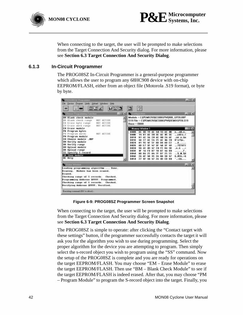
The PROG08SZ In-Circuit Programmer is a general-purpose programmerwhich allows the user to program any 68HC908 device with on-chipEEPROM/FLASH, either from an object file (Motorola .S19 format), or byteby byte.
Figure 6-9: PROG08SZ Programmer Screen Snapshot
When connecting to the target, the user will be prompted to make selectionsfrom the Target Connection And Security dialog. For more information, pleaseseeSection 6.3 Target Connection And Security Dialog.
The PROG08SZ is simple to operate: after clicking the “Contact target withthese settings” button, if the programmer successfully contacts the target it willask you for the algorithm you wish to use during programming. Select theproper algorithm for the device you are attempting to program. Then simplyselect the s-record object you wish to program using the “SS” command. Nowthe setup of the PROG08SZ is complete and you are ready for operations onthe target EEPROM/FLASH. You may choose “EM – Erase Module” to erasethe target EEPROM/FLASH. Then use “BM – Blank Check Module” to see ifthe target EEPROM/FLASH is indeed erased. After that, you may choose “PM– Program Module” to program the S-record object into the target. Finally, you
MON08 Cyclone User Manual 43
P&E MicrocomputerSystems, Inc. MON08 CYCLONEMON08 CYCLONE
may use “VC – Verify CRC Checksum” to verify that the contents are properlyprogrammed in the target memory.
6.1.4 Command Line Programmer
CPROG08SZ is a command line programmer that allows quick turn-aroundtime for programming target MCUs. The user may create a script file toinstruct the software to execute specific commands in sequence. Please refer toCPROG08SZ.pdf for more information.
6.2 Metrowerks Software
The special edition of Metrowerks’ CodeWarrior studio offers absoluteassembly and provides debugging capabilities based on P&E’s programmingand debug technologies.
6.2.1 Latest Updates - Metrowerks Software
The most recent updates of Metrowerks CodeWarrior software is available at:http://www.metrowerks.com/MW/Support/Download/default.htm?did=find&vers=CWHC08&submit=Find.
6.2.2 Metrowerks CodeWarrior
A programming or debug session with the project-based CodeWarrior IDEmay be launched by double-clicking on the project name (format isprojectname.mcp) from your file storage. Starting a new project is a little morechallenging, but the tutorials, FAQs, and Quick Start Guides are easy to followand have you building a new project, using pre-built templates, in a short time.(Seewww.Metrowerks.com/MW/Develop/and select “CodeWarriorDevelopment Studio for HC08 for Microcontrollers”.)
The following example illustrates how to program and debug an M68HC908MCU from within the CodeWarrior IDE.
Here are the main steps in programming the FLASH with CodeWarrior andstarting a debug session.
1. a. Launch the CodeWarrior CW08 software and create a new project,orb. Double-click on your project file (projectname.mcp)
44 MON08 Cyclone User Manual
P&E MicrocomputerSystems, Inc.MON08 CYCLONE
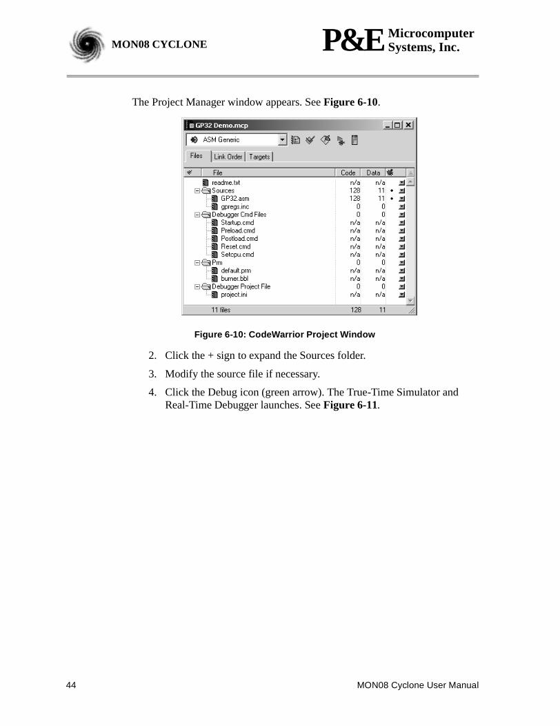
The Project Manager window appears. SeeFigure 6-10.
Figure 6-10: CodeWarrior Project Window
2. Click the + sign to expand the Sources folder.
3. Modify the source file if necessary.
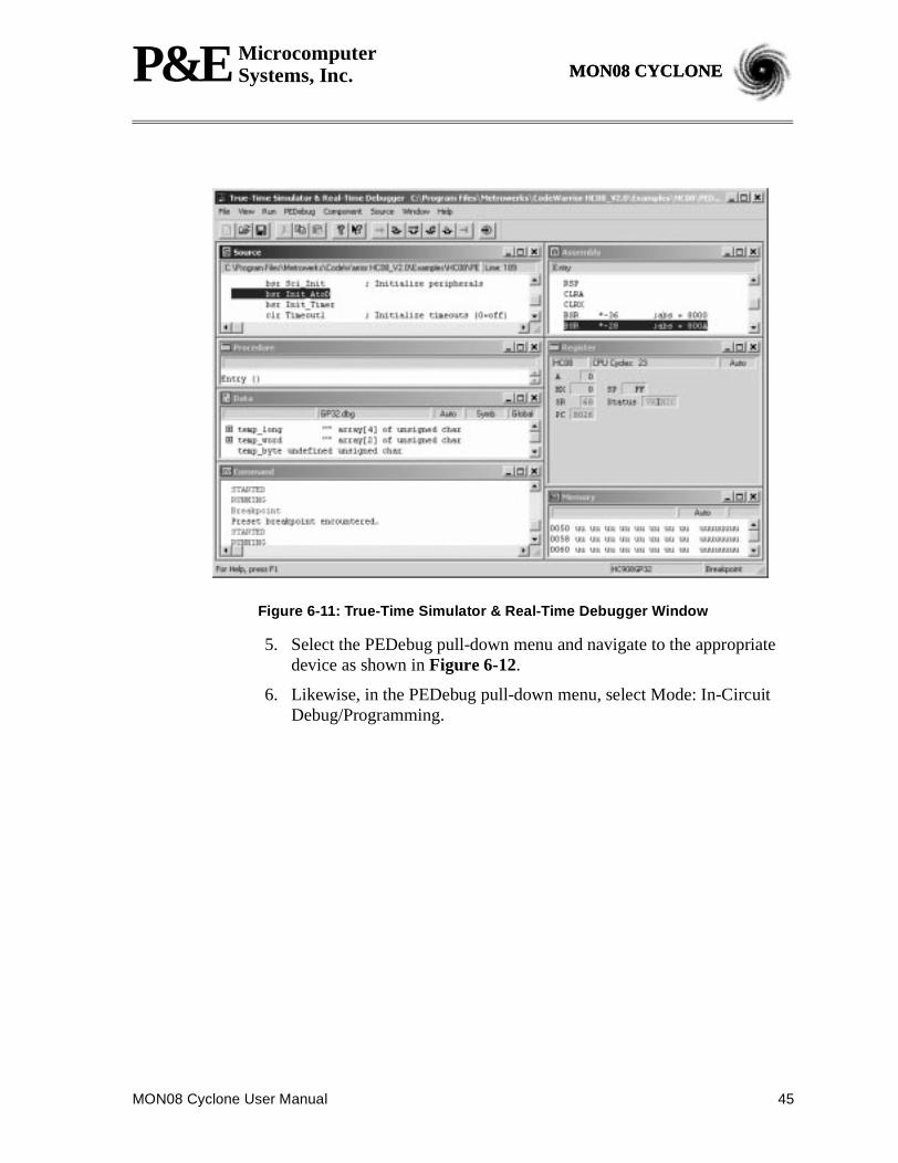
4. Click the Debug icon (green arrow). The True-Time Simulator andReal-Time Debugger launches. SeeFigure 6-11.
MON08 Cyclone User Manual 45
P&E MicrocomputerSystems, Inc. MON08 CYCLONEMON08 CYCLONE
Figure 6-11: True-Time Simulator & Real-Time Debugger Window
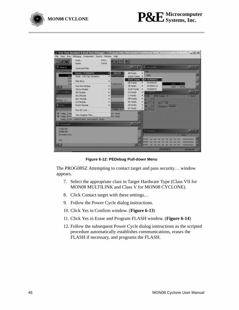
5. Select the PEDebug pull-down menu and navigate to the appropriatedevice as shown inFigure 6-12.
6. Likewise, in the PEDebug pull-down menu, select Mode: In-CircuitDebug/Programming.
46 MON08 Cyclone User Manual
P&E MicrocomputerSystems, Inc.MON08 CYCLONE
Figure 6-12: PEDebug Pull-down Menu
The PROG08SZ Attempting to contact target and pass security… windowappears.
7. Select the appropriate class in Target Hardware Type (Class VII forMON08 MULTILINK and Class V for MON08 CYCLONE).
8. Click Contact target with these settings…
9. Follow the Power Cycle dialog instructions.
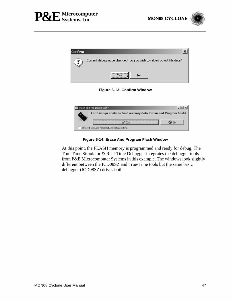
10. Click Yes in Confirm window. (Figure 6-13)
11. Click Yes in Erase and Program FLASH window. (Figure 6-14)
12. Follow the subsequent Power Cycle dialog instructions as the scriptedprocedure automatically establishes communications, erases theFLASH if necessary, and programs the FLASH.
MON08 Cyclone User Manual 47
P&E MicrocomputerSystems, Inc. MON08 CYCLONEMON08 CYCLONE
Figure 6-13: Confirm Window
Figure 6-14: Erase And Program Flash Window
At this point, the FLASH memory is programmed and ready for debug. TheTrue-Time Simulator & Real-Time Debugger integrates the debugger toolsfrom P&E Microcomputer Systems in this example. The windows look slightlydifferent between the ICD08SZ and True-Time tools but the same basicdebugger (ICD08SZ) drives both.
48 MON08 Cyclone User Manual
P&E MicrocomputerSystems, Inc.MON08 CYCLONE
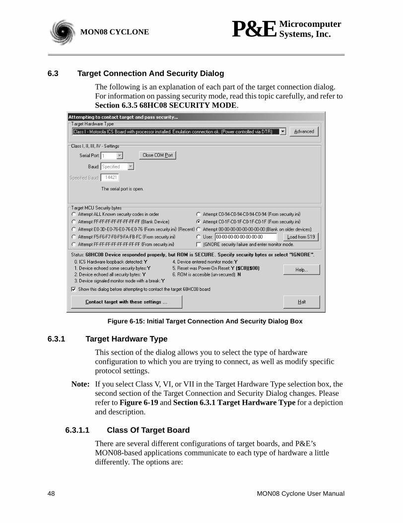
6.3 Target Connection And Security Dialog
The following is an explanation of each part of the target connection dialog.For information on passing security mode, read this topic carefully, and refer toSection 6.3.5 68HC08 SECURITY MODE.
Figure 6-15: Initial Target Connection And Security Dialog Box
6.3.1 Target Hardware Type
This section of the dialog allows you to select the type of hardwareconfiguration to which you are trying to connect, as well as modify specificprotocol settings.
Note: If you select Class V, VI, or VII in the Target Hardware Type selection box, thesecond section of the Target Connection and Security Dialog changes. Pleaserefer toFigure 6-19andSection 6.3.1 Target Hardware Typefor a depictionand description.
6.3.1.1 Class Of Target Board
There are several different configurations of target boards, and P&E’sMON08-based applications communicate to each type of hardware a littledifferently. The options are:
MON08 Cyclone User Manual 49
P&E MicrocomputerSystems, Inc. MON08 CYCLONEMON08 CYCLONE
Class I
ICS Board with processor installed. This is the standard and most commonconfiguration of the ICS08 boards. In this configuration, the processor isresident in one of the sockets on the ICS board itself. The processor can bedebugged and programmed in this configuration, and an emulation cablecontaining all the processor I/O signals can be connected to the user’starget board. In this configuration, the ICS board hardware canautomatically power up and down the processor in order to pass security inthe simplest fashion. The user has to be surenot to provide power from thetarget, up through the emulation cable, to the processor pins themselves,when this dialog appears. This is so that the software, when attempting toestablish communications, can fully power the processor down. Thesoftware running on the PC controls power to the target via the serial portDTR line. This configuration can be specified at startup in the software byusing theICS08 command-line parameter; otherwise the software willremember the hardware configuration from session to session.
Class II
ICS Board without processor, connected to target via MON08 Cable. Inthis configuration, there is no processor resident in any of the sockets ofthe ICS board itself. The processor is mounted down in the targetsystem. The connection from the ICS board to the target isaccomplished via the 16-pin MON08 connector. In this configuration,since the ICS does not control power to the processor, the user will beprompted to turn the processor’s power supply on and off. Turning offthe power supply is necessary in order to be able to pass the initialsecurity mode check and access the flash on the processor. A simplereset is not enough; to pass the security check, you must first force theprocessor to encounter a POR (power-on reset) which requires that theprocessor’s voltage dip below 0.1v. Once security has been passed,resetting the device or re-entering the software should be easier. Thisconfiguration can be specified at startup in the software by using theMON08 command-line parameter; otherwise the software willremember the hardware configuration from session to session.
Class III
Custom Board (no ICS) with MON08 serial port circuitry built in. Inthis configuration, the ICS board is not used at all. The user mustprovide a serial port connection from the PC, and provide all hardwareconfiguration necessary to force the processor into MON08 mode uponreset. This includes resets both internal and external to the processor. Inthis configuration, because the software does not directly control powerto the processor, the user will be prompted to turn the processor’s
50 MON08 Cyclone User Manual
P&E MicrocomputerSystems, Inc.MON08 CYCLONE
power supply on and off. The use will also be prompted to turn poweron and off to reset the target processor, as the PC doesn’t have controlof the target reset. Turning off the power supply is necessary mainly tobe able to pass the initial security mode check and access the flash onthe processor. A simple reset is not enough; to pass the security check,you must first force the processor to encounter a POR (power-on reset)which requires that the processor’s voltage dip below 0.1v. Oncesecurity has been passed, resetting the device or re-entering thesoftware should be easier. This configuration can be specified at startupin the software by using theNODTR command-line parameter;otherwise the software will remember the hardware configuration fromsession to session. The Class III selection also applies to use of the ICSboard with the two-pin blank part programming connector.
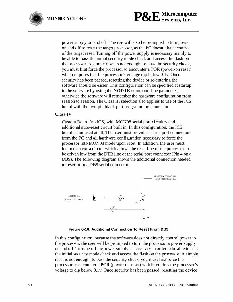
Class IV
Custom Board (no ICS) with MON08 serial port circuitry andadditional auto-reset circuit built in. In this configuration, the ICSboard is not used at all. The user must provide a serial port connectionfrom the PC and all hardware configuration necessary to force theprocessor into MON08 mode upon reset. In addition, the user mustinclude an extra circuit which allows the reset line of the processor tobe driven low from the DTR line of the serial port connector (Pin 4 on aDB9). The following diagram shows the additional connection neededto reset from a DB9 serial connector.
Figure 6-16: Additional Connection To Reset From DB9
In this configuration, because the software does not directly control power tothe processor, the user will be prompted to turn the processor’s power supplyon and off. Turning off the power supply is necessary in order to be able to passthe initial security mode check and access the flash on the processor. A simplereset is not enough; to pass the security check, you must first force theprocessor to encounter a POR (power-on reset) which requires the processor’svoltage to dip below 0.1v. Once security has been passed, resetting the device
MON08 Cyclone User Manual 51
P&E MicrocomputerSystems, Inc. MON08 CYCLONEMON08 CYCLONE
should be facilitated by the above circuitry. This configuration can be specifiedat startup in the software by using theNODTRADD command-line parameter;otherwise the software remembers the hardware configuration from session tosession.
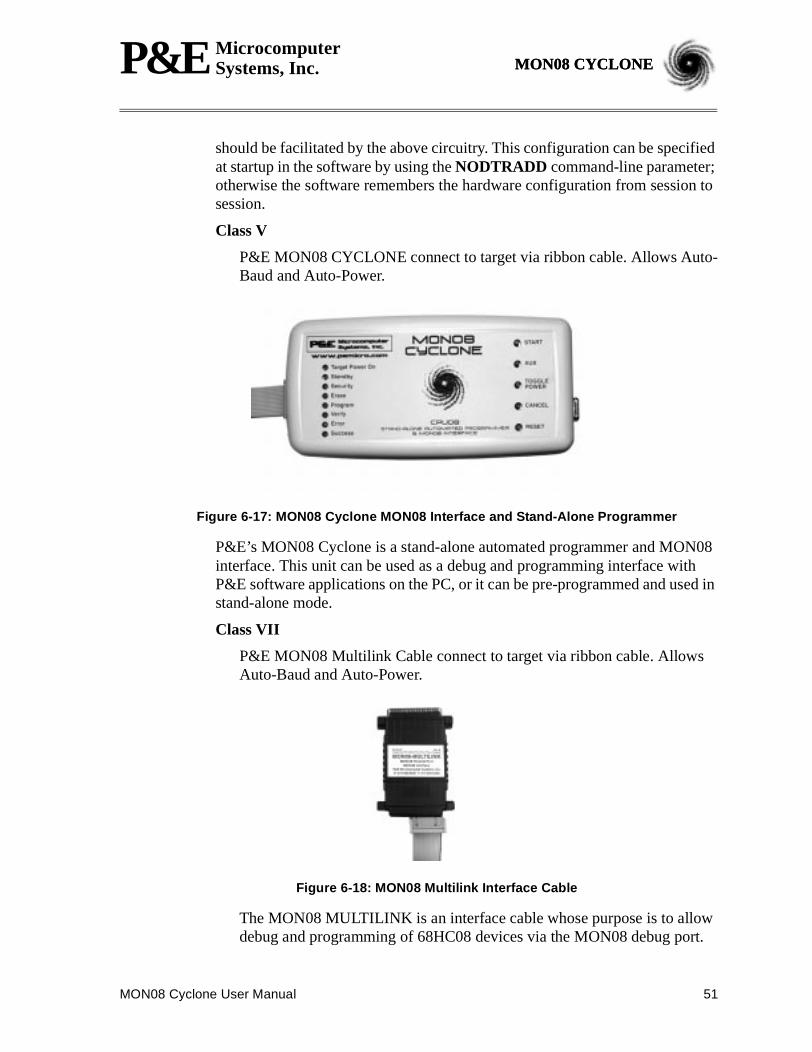
Class V
P&E MON08 CYCLONE connect to target via ribbon cable. Allows Auto-Baud and Auto-Power.
Figure 6-17: MON08 Cyclone MON08 Interface and Stand-Alone Programmer
P&E’s MON08 Cyclone is a stand-alone automated programmer and MON08interface. This unit can be used as a debug and programming interface withP&E software applications on the PC, or it can be pre-programmed and used instand-alone mode.
Class VII
P&E MON08 Multilink Cable connect to target via ribbon cable. AllowsAuto-Baud and Auto-Power.
Figure 6-18: MON08 Multilink Interface Cable
The MON08 MULTILINK is an interface cable whose purpose is to allowdebug and programming of 68HC08 devices via the MON08 debug port.
52 MON08 Cyclone User Manual
P&E MicrocomputerSystems, Inc.MON08 CYCLONE
The MON08 MULTILINK connects the target to the PC via a standardparallel port.
Note: If you select Class V, VI, or VII in the Target Hardware Type selection box, thesecond section of the Target Connection and Security Dialog changes. Pleaserefer toFigure 6-19andSection 6.3.1 Target Hardware Typefor a depictionand description.
Also:
For the simulator, the/SIM08 command-line parameter causes the software todisconnect from the target and enter Simulation Only mode.
For information on passing security mode, read this topic carefully and alsorefer toSection 6.3.5 68HC08 SECURITY MODE.
MON08 Cyclone User Manual 53
P&E MicrocomputerSystems, Inc. MON08 CYCLONEMON08 CYCLONE
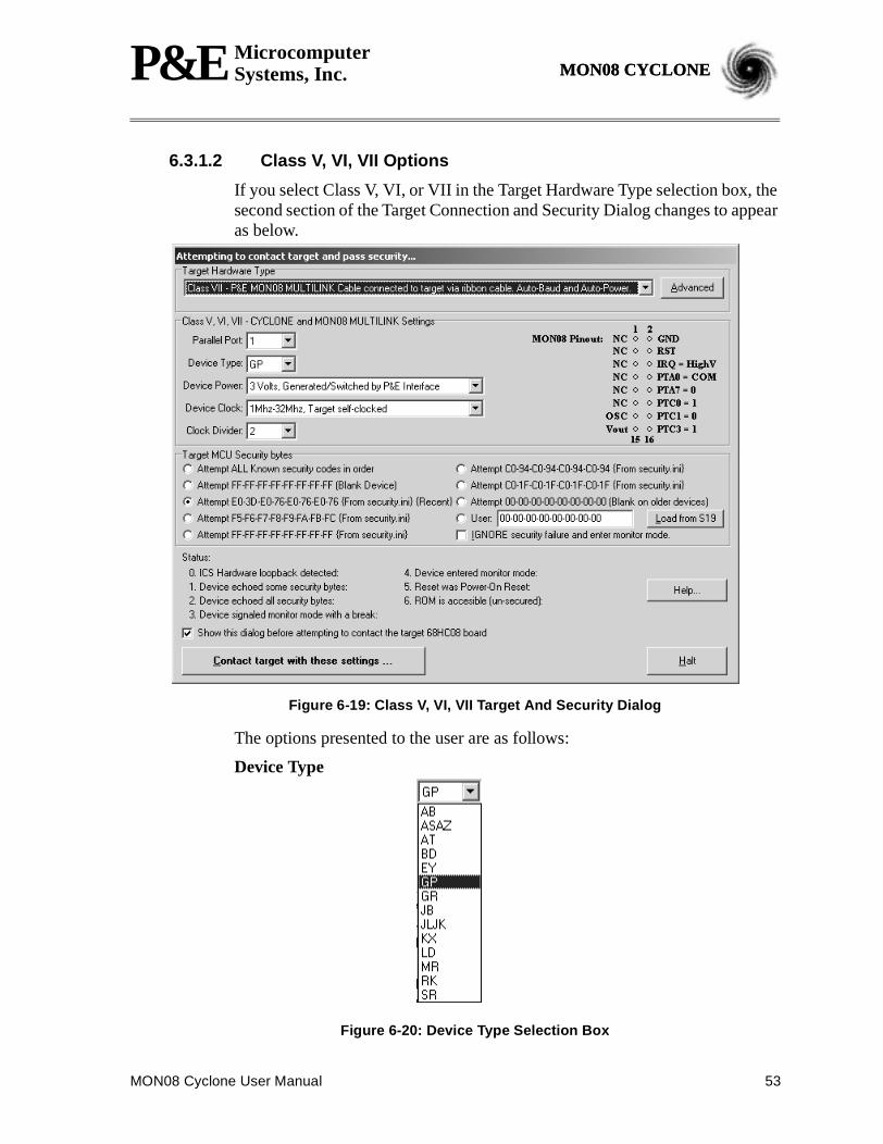
6.3.1.2 Class V, VI, VII Options
If you select Class V, VI, or VII in the Target Hardware Type selection box, thesecond section of the Target Connection and Security Dialog changes to appearas below.
Figure 6-19: Class V, VI, VII Target And Security Dialog
The options presented to the user are as follows:
Device Type
Figure 6-20: Device Type Selection Box
54 MON08 Cyclone User Manual
P&E MicrocomputerSystems, Inc.MON08 CYCLONE
The device type selection box allows the user to specify what type of HC08they are communicating with. The dialog will then display the appropriatepinout to be implemented on the MON08 connector, so that the P&E interfacecan talk to it properly. The values given (1 or 0) are for informational purposesonly and are driven by the P&E interface.
Device Power
Figure 6-21: Device Power Dialog
The device power selection allows the user to specify whether the target is 2, 3,or 5 Volts, and whether this power is switched/generated by the P&E interfaceor if it is separately supplied to the target and under user control. If it is underuser control, the software will use dialog boxes to ask the user to power thetarget up and down when necessary (similar to Class II-IV).
Device Clock
Figure 6-22: Device Clock Selection Box
The device clock menu allows three options:
1) P&E provides clock to target
2) The target has its own clock (1-32MHz)
3) The target has a slow crystal (30KHz-100KHz) with PLL circuitry. P&Etries to enable the PLL to allow programming and debug at higher speeds.
Baud
There is no need to set baud rate for Class V, VI, or VII targets, as it is auto-detected from the target.
MON08 Cyclone User Manual 55
P&E MicrocomputerSystems, Inc. MON08 CYCLONEMON08 CYCLONE
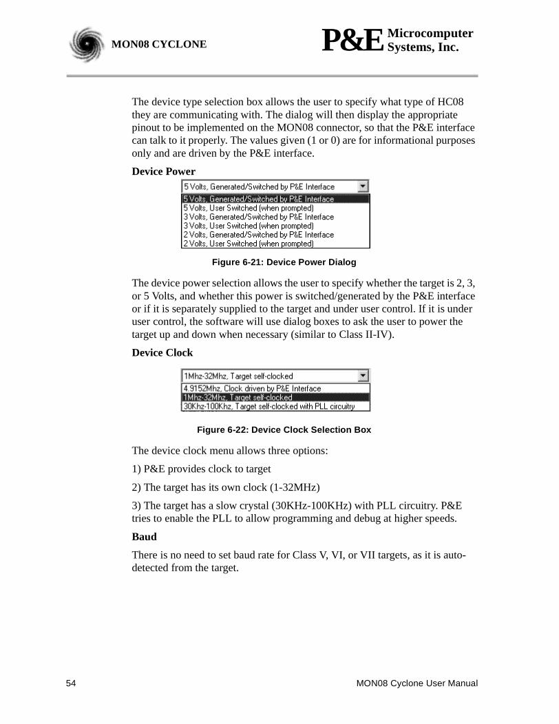
6.3.1.3 Advanced Settings Dialog
The Advanced Button brings up a dialog which allows the user to set specificprotocol settings. The following is an explanation of each part of the advancedsettings dialog.
Figure 6-23: Target Hardware Type: Advanced Settings Dialog
Tpd and Tpu Timing
These timing parameters are mostly designed for Class I boards, although thedelays are valid for all classes of boards. Many of the ICS boards and usertarget boards need time to power down and power up.
Whenever power is automatically switched off, or is manually requested to beswitched off, the software waits for an amount of time equal to the Tpd delaytime before proceeding to the connection protocol. This is because a board orpower supply may have capacitance which holds the power up for a short timeafter the supply has been switched off, but the supply voltage must reach lessthan 0.1v before it is turned back on if a Power-On reset is to occur.
Whenever power is automatically switched on, or is manually requested to beswitched on, the software waits for an amount of time equal to the Tpu delaytime before attempting to contact the 68HC08 processor. This is to allow timenot only for power to be fully available, but to wait until any reset driver hasfinally released the RESET line. On many ICS08 boards (such as theICS08RK, M68ICS08JL3, M68ICS08JLJK, and ICS08GP20) the Tpu can bedecreased to as little as 250ms with no adverse effects.
Target has RESET button (class III boards only):The softwareoccasionally needs to get control of the target. On systems which are Class IIIboards with the monitor mode circuitry built-in (including RS-232 driver),there is no means to reset the target to gain control. If the board has a reset
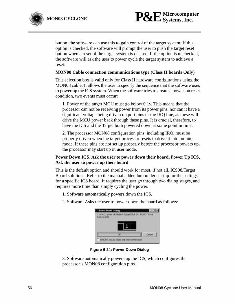
56 MON08 Cyclone User Manual
P&E MicrocomputerSystems, Inc.MON08 CYCLONE
button, the software can use this to gain control of the target system. If thisoption is checked, the software will prompt the user to push the target resetbutton when a reset of the target system is desired. If the option is unchecked,the software will ask the user to power cycle the target system to achieve areset.
MON08 Cable connection communications type (Class II boards Only)
This selection box is valid only for Class II hardware configurations using theMON08 cable. It allows the user to specify the sequence that the software usesto power up the ICS system. When the software tries to create a power-on resetcondition, two events must occur:
1. Power of the target MCU must go below 0.1v. This means that theprocessor can not be receiving power from its power pins, nor can it have asignificant voltage being driven on port pins or the IRQ line, as these willdrive the MCU power back through these pins. It is crucial, therefore, tohave the ICS and the Target both powered down at some point in time.
2. The processor MON08 configuration pins, including IRQ, must beproperly driven when the target processor resets to drive it into monitormode. If these pins are not set up properly before the processor powers up,the processor may start up in user mode.
Power Down ICS, Ask the user to power down their board, Power Up ICS,Ask the user to power up their board
This is the default option and should work for most, if not all, ICS08/TargetBoard solutions. Refer to the manual addendum under startup for the settingsfor a specific ICS board. It requires the user go through two dialog stages, andrequires more time than simply cycling the power.
1. Software automatically powers down the ICS.
2. Software Asks the user to power down the board as follows:
Figure 6-24: Power Down Dialog
3. Software automatically powers up the ICS, which configures theprocessor’s MON08 configuration pins.
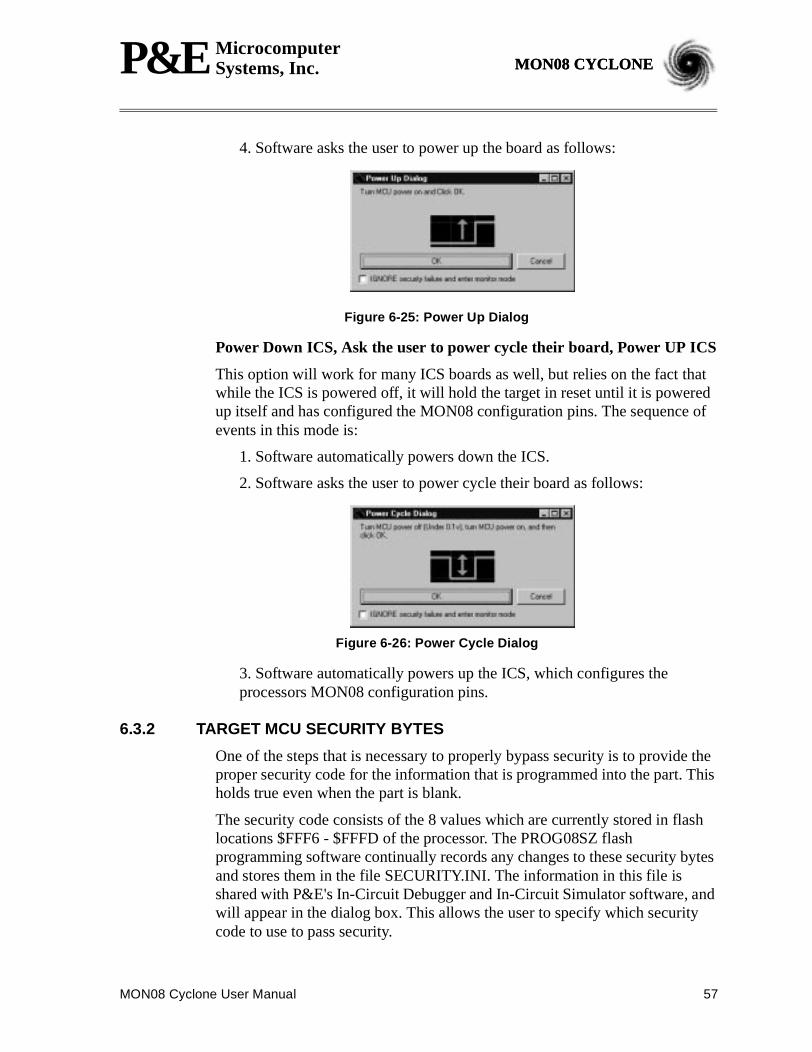
MON08 Cyclone User Manual 57
P&E MicrocomputerSystems, Inc. MON08 CYCLONEMON08 CYCLONE
4. Software asks the user to power up the board as follows:
Figure 6-25: Power Up Dialog
Power Down ICS, Ask the user to power cycle their board, Power UP ICS
This option will work for many ICS boards as well, but relies on the fact thatwhile the ICS is powered off, it will hold the target in reset until it is poweredup itself and has configured the MON08 configuration pins. The sequence ofevents in this mode is:
1. Software automatically powers down the ICS.
2. Software asks the user to power cycle their board as follows:
Figure 6-26: Power Cycle Dialog
3. Software automatically powers up the ICS, which configures theprocessors MON08 configuration pins.
6.3.2 TARGET MCU SECURITY BYTES
One of the steps that is necessary to properly bypass security is to provide theproper security code for the information that is programmed into the part. Thisholds true even when the part is blank.
The security code consists of the 8 values which are currently stored in flashlocations $FFF6 - $FFFD of the processor. The PROG08SZ flashprogramming software continually records any changes to these security bytesand stores them in the file SECURITY.INI. The information in this file isshared with P&E's In-Circuit Debugger and In-Circuit Simulator software, andwill appear in the dialog box. This allows the user to specify which securitycode to use to pass security.
58 MON08 Cyclone User Manual
P&E MicrocomputerSystems, Inc.MON08 CYCLONE
This dialog can also be used by the user to manually enter the proper securitybytes via the USER setting, or to load the security bytes from the same .S19file which was programmed. The bytes are loaded from an .S19 file by clickingthe “Load from S19” button.
IGNORE security failure and enter monitor mode
This checkbox can be used to cause the software to ignore a failure toproperly pass the 68HC08 security check. If the checkbox is set, thesoftware will attempt to establish monitor mode communicationsregardless of the security status. As long as the Baud and Port are correct,and the device has been properly powered, this will allow monitor modeentry. Note that by ignoring the security check failure, you may usemonitor mode, but the ROM/Flash will not be accessible.
The checkbox can be set to be checked on startup via theFORCEBYPASScommand-line parameter, which will cause the software to ignore securitycheck failure. This checkbox can be overridden to beunchecked on startupvia theFORCEPASScommand-line parameter, which will cause thesoftware to pop-up the connection dialog when the security check hasfailed. Note that if a connection is not established for a reason other thansecurity failure, the connection dialog will always appear.
6.3.3 STATUS
The status area consists of one status string following the “Status:” label, andseven items which list the state of the last attempt to connect to a target andpass security. The description for these items is as follows:
0 – ICS Hardware loopback detected:
Every ICS or board which supports MON08 has a serial loopback inhardware which, by connecting the transmit and receive lines,automatically echoes characters from the PC. A valid character transmittedfrom the PC should be echoed once by the loopback circuitry on the boardand once by the monitor of the target processor itself. This status indicateswhether or not the first echoed character from the hardware loopback wasreceived when one of the security bytes was transmitted. If the status is‘N’, which indicates that the character was not received, it is most likelydue to one of the following reasons:
1. Wrong Com Port specified.
2. The baud rate specified was incorrect (probably too low).
3. The ICS/Target is not connected.
4. No Power to the ICS.
If this status bit responded with an ‘N’, you must correct this before
MON08 Cyclone User Manual 59
P&E MicrocomputerSystems, Inc. MON08 CYCLONEMON08 CYCLONE
analyzing the reset of the status bits.
1 – Device echoed some security bytes:
The monitor resident in a 68HC08 device automatically echoes everyincoming character when it is in monitor mode. A valid charactertransmitted from the PC should be echoed once by the loopback circuitryon the board and once by the monitor of the target processor itself. Thisstatus indicates whether or not the second echoed character from themonitor response was received when one of the security bytes wastransmitted. If the status is ‘N’, which indicates that the character was notreceived, or not received properly, it is most likely due to one of thefollowing reasons:
1. The baud rate specified was incorrect.
2. The part did not start the monitor mode security check on reset.Signals to force monitor mode may be incorrect.
3. No Power to the ICS.
If this status bit responded with an ‘N’, you must correct this beforeanalyzing the reset of the status bits.
2 – Device echoed all security bytes:
In order to pass security, the software must send 8 security bytes to theprocessor. The processor should echo each of these eight bytes twice. If all8 bytes did not get the proper two-byte echo, this flag will be ‘N’. Reasonsfor this include:
1. The part did not start the monitor mode security check on reset.Signals to force monitor mode may be incorrect.
2. The baud rate specified was incorrect.
3. The processor was not reset properly. Check the “Target HardwareType” and if you are connecting to a class II board, check the “MON08cable communication connections type” in the “advanced settings”dialog.
3 – Device signaled monitor mode with a break:
Once the processor has properly received the 8 bytes from the PC softwareto complete its security check, it should transmit a break character to thePC signaling entry into monitor mode. This break should be sent regardlessof whether the security check was successfully passed. If a break was notreceived from the processor, this flag will be ‘N’. Reasons for this include:
1. The baud rate specified was incorrect.
2. The processor was not reset properly. Check the “Target Hardware
60 MON08 Cyclone User Manual
P&E MicrocomputerSystems, Inc.MON08 CYCLONE
Type”. If you are connecting to a class II board, check the “MON08cable communication connections type” in the “advanced settings”dialog.
4 – Device entered monitor mode:
Once the software has received, or failed to receive, a break from theprocessor, it attempts to communicate with the monitor running on the68HC08 processor. It tries to read the monitor version number by issuing amonitor mode read. If the processor fails to respond properly to thiscommand, this flag will be ‘N’.
5 – Reset was Power-On Reset:
If the device properly entered monitor mode (4), the software will read thereset status register (RSR). This read does not affect the security sequence,and occurs purely for diagnostic reasons. The reset status register indicatesthe conditions under which the processor underwent the last reset. For thesoftware to pass the security check properly, it MUST first cause theprocessor to undergo a Power-On Reset. The software reads the reset statusregister to determine if the last reset was indeed caused by power-on. Theresult of the reset status register is indicated in parentheses after the flagvalue. If the highest bit is not set then the reset was not a power on reset,and the flag will indicate ‘N’. Reasons for this include:
1. The processor did not power all the way down because power wasbeing supplied to the processor through either the port pins, IRQ line,RESET line, or power pins.
2. The voltage driven on the power pin of the processor did not gobelow 0.1 volts.
3. The processor was not reset properly. Check the “Target HardwareType”. If you are connecting to a class II board, check the “MON08cable communication connections type” in the “advanced settings”dialog.
6 – ROM is accessible (un-secured):
If the device properly entered monitor mode (4), the software readslocations $FFF6-$FFFF to determine if the processor passes the securitycheck. Memory locations which are invalid or protected read back from thedevice as $AD. If all bytes from $FFF6-$FFFF read a value of $AD, it isassumed the device is secure, and the flag value is an ‘N’. If all flags 0-5register a value of ‘Y’ and flag 6 register a value of ‘N,’ then the resetprocess has gone correctly except that the security code used to passsecurity was incorrect. Specify the correct security code and try again, orIGNORE the security failure and erase the device. Once you erase asecured device, you must exit the software and restart it in order to pass
MON08 Cyclone User Manual 61
P&E MicrocomputerSystems, Inc. MON08 CYCLONEMON08 CYCLONE
security.
6.3.4 ADDITIONAL DIALOG BUTTONS
The following buttons are also available:
Contact target with these settings– This causes the software to attempt tocause a power on reset of the target, and to attempt to pass security with thesettings in this dialog.
Simulation Only – This button is only visible in In-Circuit Simulation. Thiscauses the In-Circuit Simulator not to use the target and, instead, to docompletely software-based simulation. The/SIM08 command-line parameterhas the same function.
Halt – This causes the software to terminate and return to the callingenvironment.
6.3.5 68HC08 SECURITY MODE
Monitor mode is a special mode on the 68HC08 device which allows anexternal host to control the 68HC08 microcontroller via an asynchronous serialinterface. This feature allows a host computer to query and modify the state ofthe processor including to load, debug, and program code. Without anyprotection mechanism, this same feature could be used to read out the internalsof the microcontrollers ROM.
The M68HC08 microcontrollers have a additional built-in mechanism toprotect a programmed device from being read and disassembled. Themechanism allows a user who knows the security unlock code to enter monitormode and access the internal ROM/flash. This is often desirable to allow real-time debugging of a programmed device. The ICD08SZ allows just suchfunctionality.
The security mechanism also allows a user who doesn’t know the security codeto enter monitor mode, but doesn’t give them access to the ROM. Upon failingthe security protocol, the ROM/Flash is removed from the memory map untilthe next POWER-ON reset, in which case the host has to bypass securityagain. The advantage of this is that even though any on-chip flash is not READaccessible, it is erasable. Forgotten what you programmed into your device?The answer is simple: erase it.
A device is automatically protected in this manner. The 8 bytes from address$FFF6 to $FFFD constitute the security unlock code which can be used to passthe security check and get access to the ROM/Flash. Hence, if a user knowswhat has been programmed into a device, they implicitly know the securityunlock code.
In order to facilitate passing the security check on a 68HC08 device, the
62 MON08 Cyclone User Manual
P&E MicrocomputerSystems, Inc.MON08 CYCLONE
PROG08SZ software continually records any changes to these security bytesand stores them in the file SECURITY.INI. The information in this file is alsoshared with P&E's In-Circuit Debugger and In-Circuit Simulator Software.This allows the user to reset the device and still have access to the monitormode.
Sometimes the case comes up where the software can’t pass security mode.The Target Connection and Security Dialog section has a “STATUS” sectionwhich describes the different failures and what to check in each case.
The most common reasons for not passing security are:
- You are not choosing the proper security code to pass security.
- On a power on reset, the device is not powering down to below 0.1volts. With a Class I board (ICS with processor), you may be drivingthe pins on the emulation header while the device is being powereddown. This back-drives current through the ports and doesn’t let thedevice fully power down. On other classes of boards, when promptedto power down the device, the supply voltage might not be droppinglower than 0.1v which it must to have a power-on reset.
- Make sure the “Target hardware type” is set to the proper class ofhardware.
There are several ways you can specify the proper security bytes:
- If you know the programmed security bytes, i.e. the bytes from$FFF6-$FFFD, you can enter them in the edit box listed “User:” andclick OK(Retry).
- You can use the “Load from S19” to specify the s-record file whichcontains the object information currently programmed into the MCU.P&E’s software will automatically extract the security informationfrom this file and use it to pass security. Once you have specified thes-record file, click the OK(Retry) button.
- You can erase the device. Run the PROG08SZ application, and when theabove box appears, select the “IGNORE security failure…” option and clickOK. Use the Choose Module command to select the appropriate programmingalgorithm, and select Erase Module. This should erase the device. You willhave to execute the Choose Module command again before you can access theblank device. Note: on some older revisions of silicon, you can’t ignore thesecurity failure, and it will bring this box back up every time you clickOK(Retry). If this is the case, you should obtain the latest silicon revision fromMotorola.


