29
MONITORING AND FAULT DIAGNOSIS OF INDUCTION MOTORS EE7000-1 1 Oly Paz
| Date post: | 23-Dec-2015 |
| Category: |
Documents |
| Upload: | lynne-morrison |
| View: | 219 times |
| Download: | 1 times |
MONITORING AND FAULT DIAGNOSIS OF INDUCTION
MOTORSEE7000-1
1Oly Paz
Motor Fault and Diagnosis• Safety,• Reliability,• Efficiency, and • Performance are some of the major concerns
and needs for motor systems applications.
For a successful motor operation the keys are:
• Quality of the motor,
• Understanding of the application,
• Choice of the proper type of motor for application, and
• Proper maintenance of the motor.

Induction Motor
Major faults of electrical machines:
• Stator faults resulting in the opening or shorting of one or more of stator phase winding,
• Abnormal connection of the stator windings,
• Broken rotor bar or cracked rotor end-rings,
• Static and or dynamic air-gap irregularities,
• Bent shaft (akin to dynamic eccentricity) which can result in a rub between the rotor and stator,
• Shorter rotor field winding, and
• Bearing and gearbox failures
Symptoms produced for one or more of these faults:
• Unbalanced air-gap voltages and lines currents,
• Increases torque pulsations,
• Decreased average torque,
• Increased losses and reduction in efficiency, and
• Excessive heating.
The diagnostic methods to identify these faults can be:
• Electromagnetic field monitoring, search coils, coils wound around motor shafts,
• Temperature measurements,• Infrared recognition,• Radio frequency (RF) emissions monitoring,• Noise and vibration monitoring,• Chemical analysis,• Acoustic noise measurements,• Motor current signature analysis (MCSA),• Model, artificial intelligence and neural network
based techniques.
ON-LINE CONDITION MONITORING OF MOTORS
USING ELECTRICAL SIGNATURE ANALYSIS
• Electrical signature analysis is the procedure of acquiring the motor current and voltage signals, performing signal conditioning and analyzing the derived signals to identify the various faults.
• A FFT (Fast Fourier Transform) analyzer is required for converting the signals from the time domain to the frequency domain.

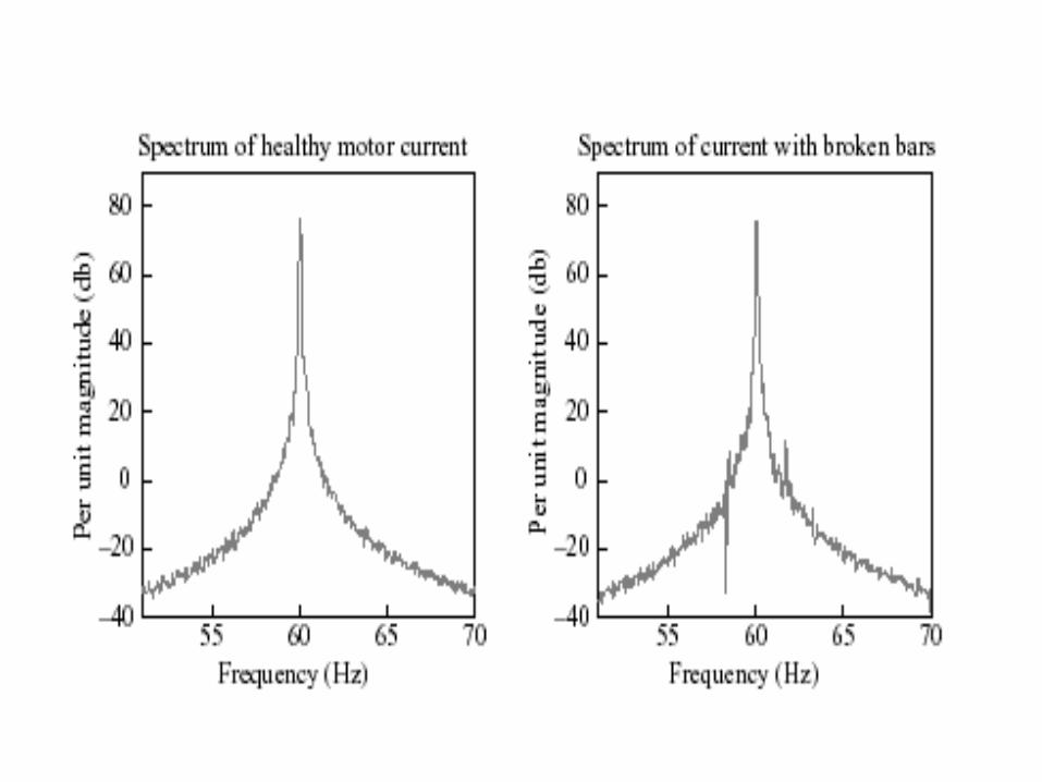
A motor current signal is ideally a perfect sinusoidal wave at 50 Hz.The amplitude of the peak in frequency is equal to RMS amplitude of the sine wave. As this theoretical situation with no harmonics, we see only one peak in the frequency spectrum.
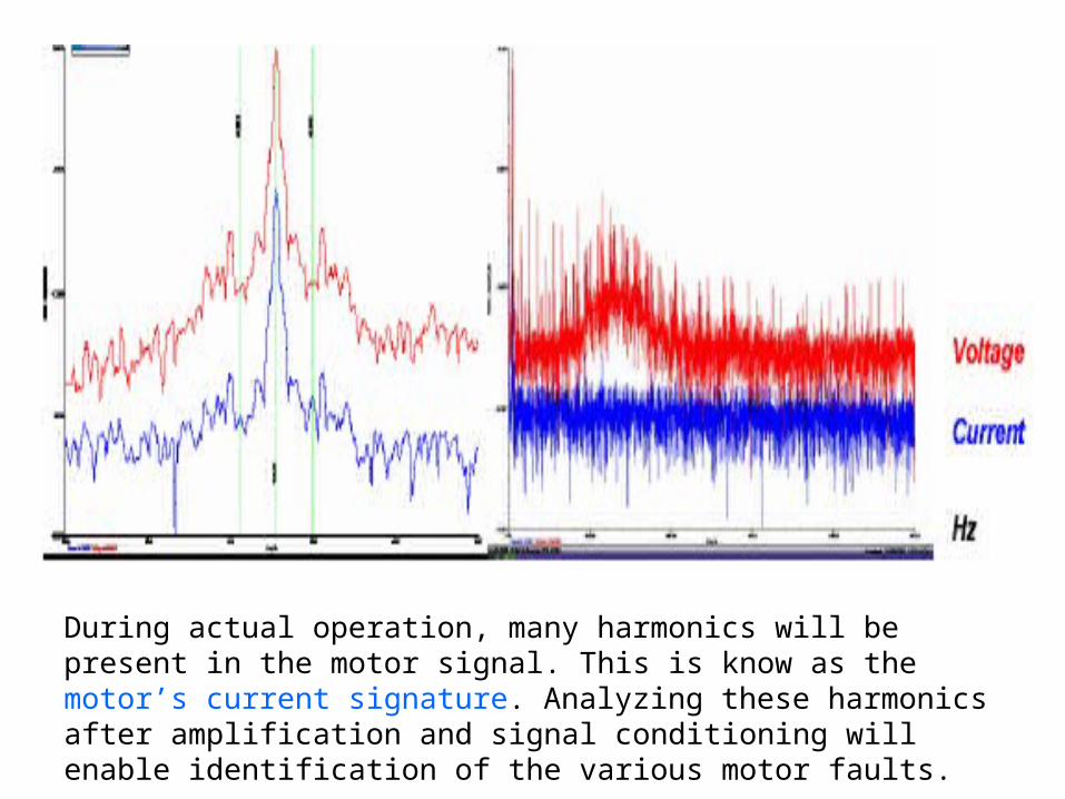
During actual operation, many harmonics will be present in the motor signal. This is know as the motor’s current signature. Analyzing these harmonics after amplification and signal conditioning will enable identification of the various motor faults.
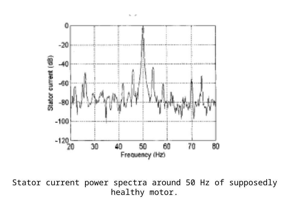
Stator current power spectra around 50 Hz of supposedly healthy motor.
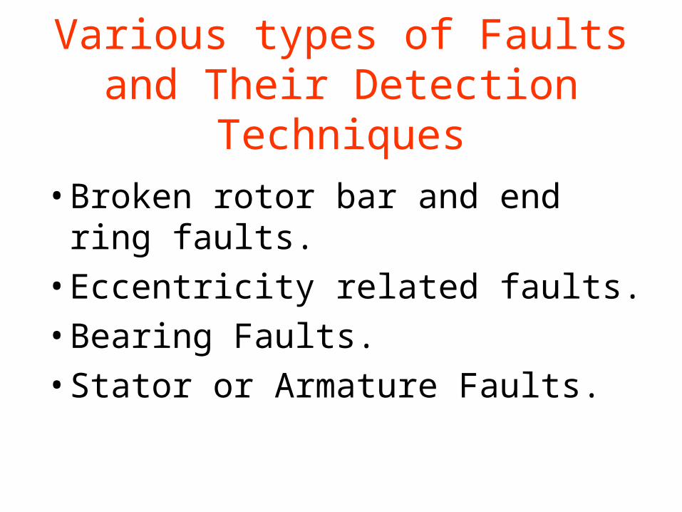
Various types of Faults and Their Detection Techniques
• Broken rotor bar and end ring faults.
• Eccentricity related faults.
• Bearing Faults.
• Stator or Armature Faults.
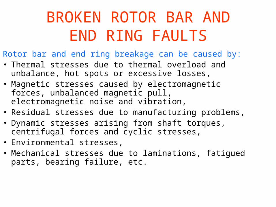
BROKEN ROTOR BAR ANDEND RING FAULTS
Rotor bar and end ring breakage can be caused by:• Thermal stresses due to thermal overload and
unbalance, hot spots or excessive losses,• Magnetic stresses caused by electromagnetic forces,
unbalanced magnetic pull, electromagnetic noise and vibration,
• Residual stresses due to manufacturing problems,• Dynamic stresses arising from shaft torques,
centrifugal forces and cyclic stresses,• Environmental stresses,• Mechanical stresses due to laminations, fatigued
parts, bearing failure, etc.
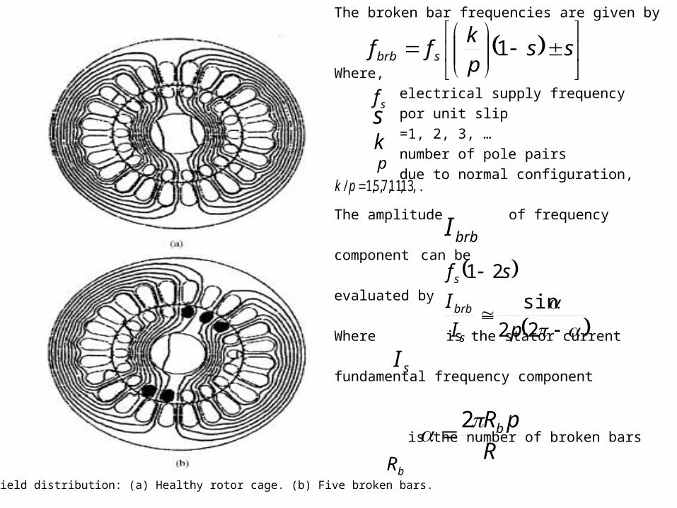
Magnetic field distribution: (a) Healthy rotor cage. (b) Five broken bars.
The broken bar frequencies are given by
Where,
electrical supply frequency
por unit slip
=1, 2, 3, …
number of pole pairs
due to normal configuration,
The amplitude of frequency
component can be
evaluated by
Where is the stator current
fundamental frequency component
is the number of broken bars
ss
p
kff sbrb 1
sfskp
,...13,11,7,5,1/ pk
brbI
sf s 21
22
sin
pI
I
s
brb
sI
R
pRb 2bR
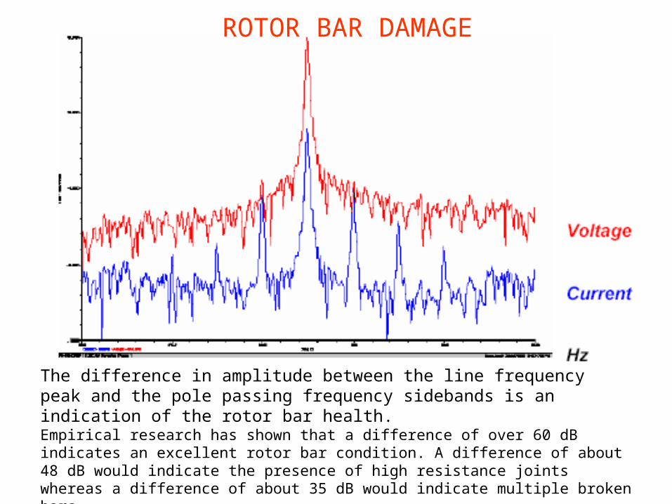
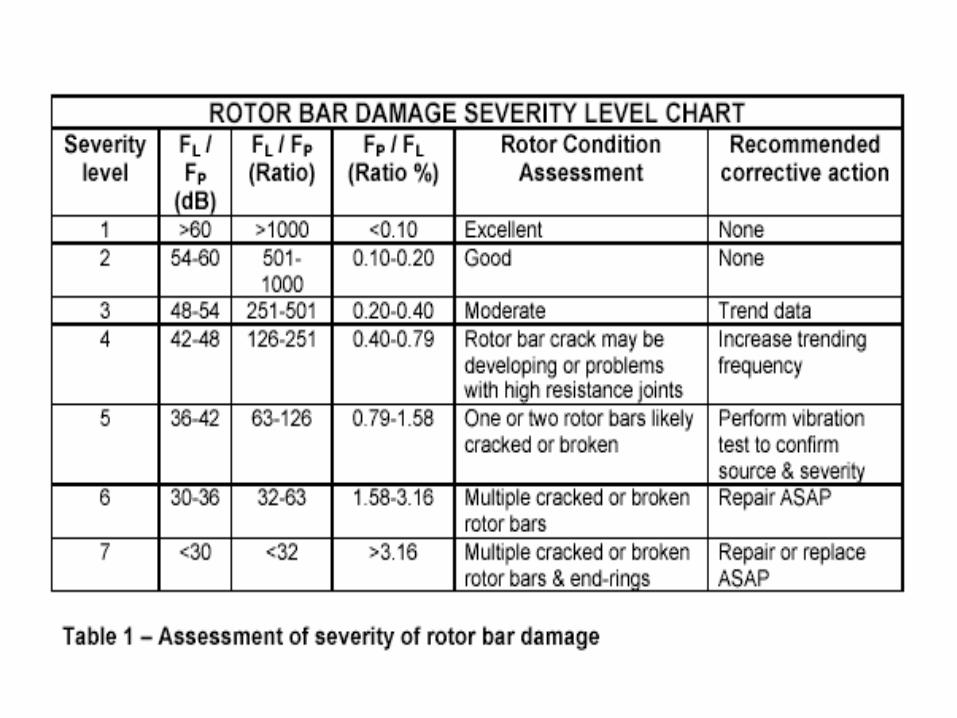
The difference in amplitude between the line frequency peak and the pole passing frequency sidebands is an indication of the rotor bar health. Empirical research has shown that a difference of over 60 dB indicates an excellent rotor bar condition. A difference of about 48 dB would indicate the presence of high resistance joints whereas a difference of about 35 dB would indicate multiple broken bars.
ROTOR BAR DAMAGE

ECCENTRICITY RELATED FAULTS
There are two types of air gap eccentricity:
• The static air gap eccentricity, and
• The dynamic air gap eccentricity.
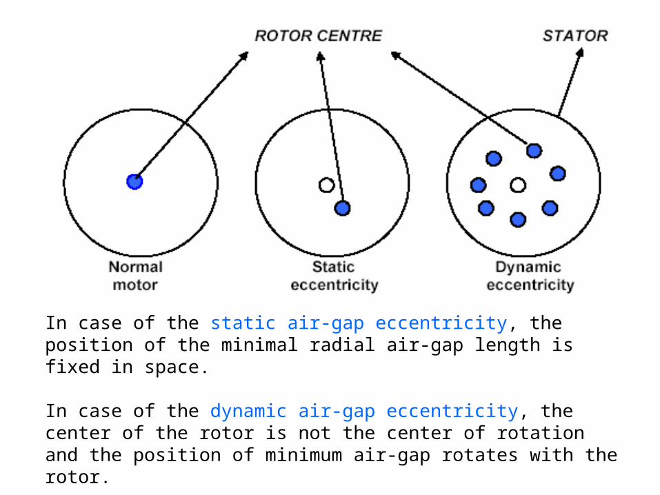
In case of the static air-gap eccentricity, the position of the minimal radial air-gap length is fixed in space.
In case of the dynamic air-gap eccentricity, the center of the rotor is not the center of rotation and the position of minimum air-gap rotates with the rotor.
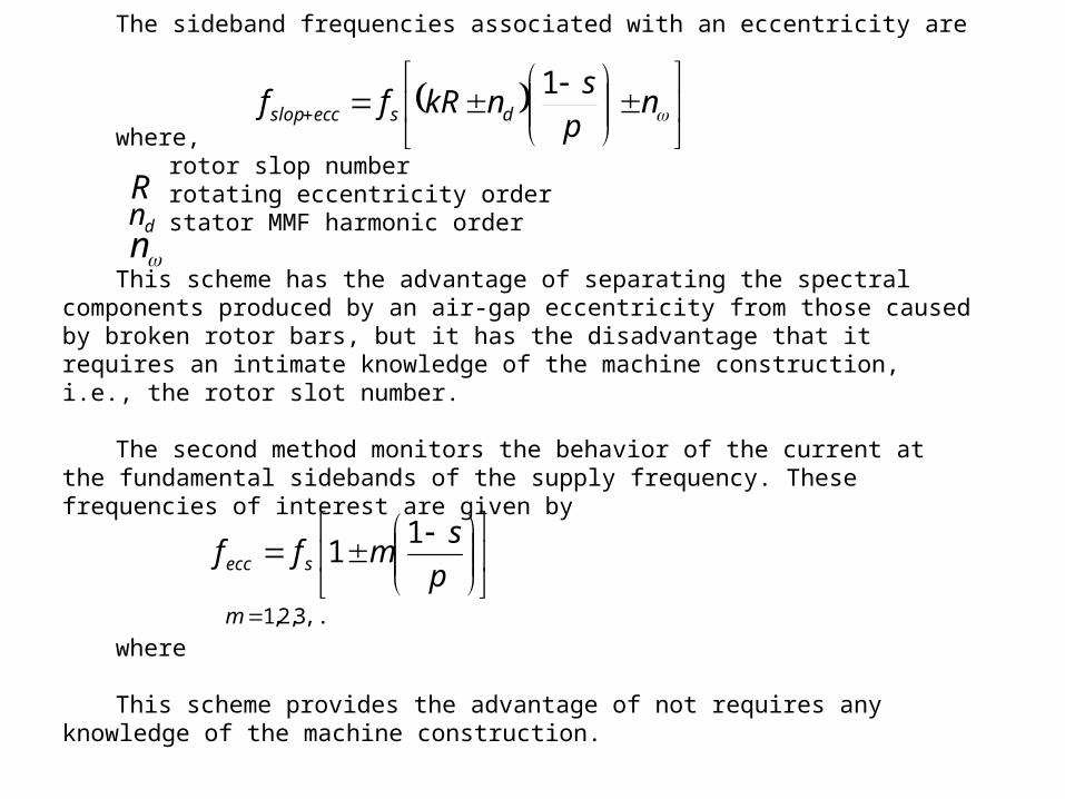
The sideband frequencies associated with an eccentricity are
where,rotor slop numberrotating eccentricity orderstator MMF harmonic order
This scheme has the advantage of separating the spectral components produced by an air-gap eccentricity from those caused by broken rotor bars, but it has the disadvantage that it requires an intimate knowledge of the machine construction, i.e., the rotor slot number.
The second method monitors the behavior of the current at the fundamental sidebands of the supply frequency. These frequencies of interest are given by
where
This scheme provides the advantage of not requires any knowledge of the machine construction.
Rdn
n
p
smff secc
11
,...3,2,1m
nps
nkRff dseccslop
1
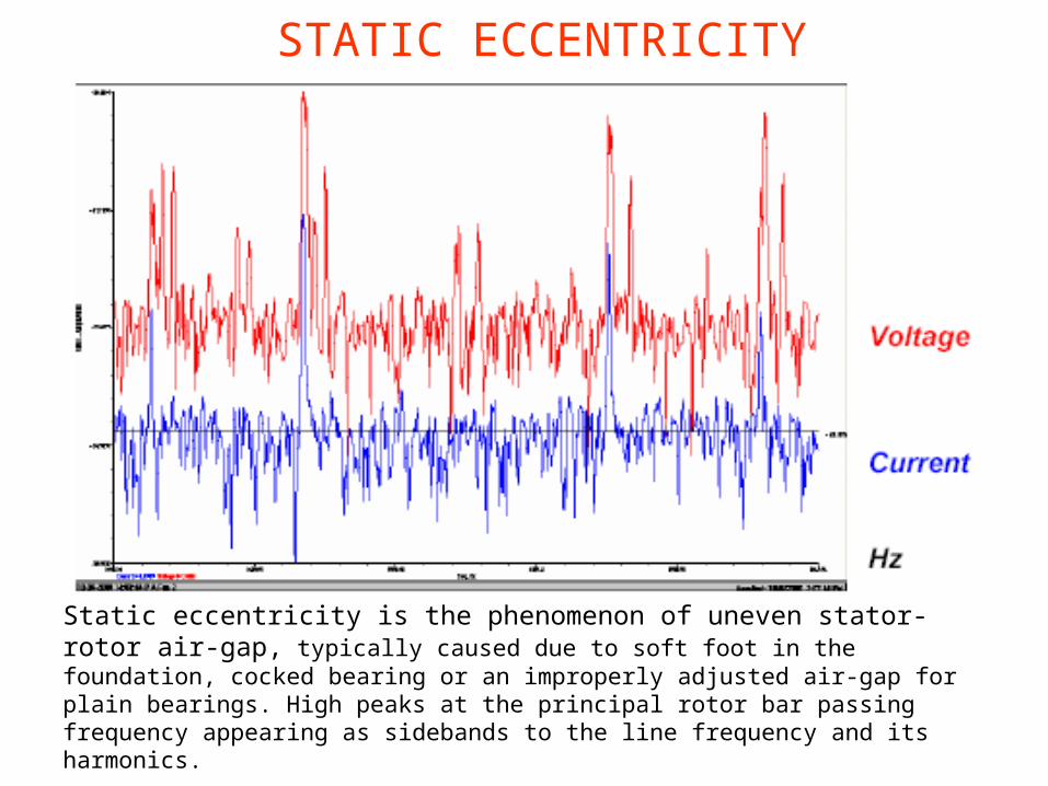
Static eccentricity is the phenomenon of uneven stator-rotor air-gap, typically caused due to soft foot in the foundation, cocked bearing or an improperly adjusted air-gap for plain bearings. High peaks at the principal rotor bar passing frequency appearing as sidebands to the line frequency and its harmonics.
STATIC ECCENTRICITY

DYNAMIC ECCENTRICITY
Dynamic eccentricity is the phenomenon of a variable stator-rotor air-gap, typically caused due to worn out bearing housings or end covers. High peaks at the principal rotor bar passing frequency and its harmonics along with the running speed sidebands around these.
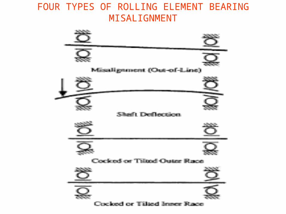
FOUR TYPES OF ROLLING ELEMENT BEARING MISALIGNMENT
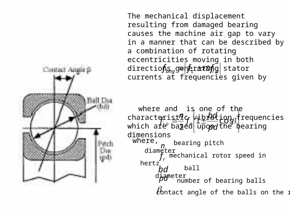
oisbng mfff ,
cos1
2, pd
bdf
nf roi
where, n
number of bearing balls
rf mechanical rotor speed in hertzbd ball diameter
pd
bearing pitch diameter
contact angle of the balls on the race
The mechanical displacement resulting from damaged bearing causes the machine air gap to vary in a manner that can be described by a combination of rotating eccentricities moving in both directions generating stator currents at frequencies given by
where and is one of the characteristic vibration frequencies which are based upon the bearing dimensions
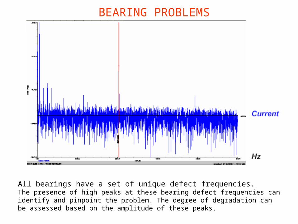
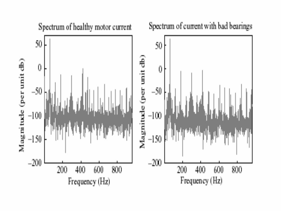
All bearings have a set of unique defect frequencies.The presence of high peaks at these bearing defect frequencies can identify and pinpoint the problem. The degree of degradation can be assessed based on the amplitude of these peaks.
BEARING PROBLEMS
STATOR OR ARMATURE FAULTS
Stator insulation can fail due to several reasons:• High stator core or winding temperatures,• Slack core lamination, slot wedges and joints,• Loose bracing for end winding,• Contamination due to oil, moisture and dirt,• Short circuit or starting stresses,• Electrical discharges,• Leakage in cooling systems.
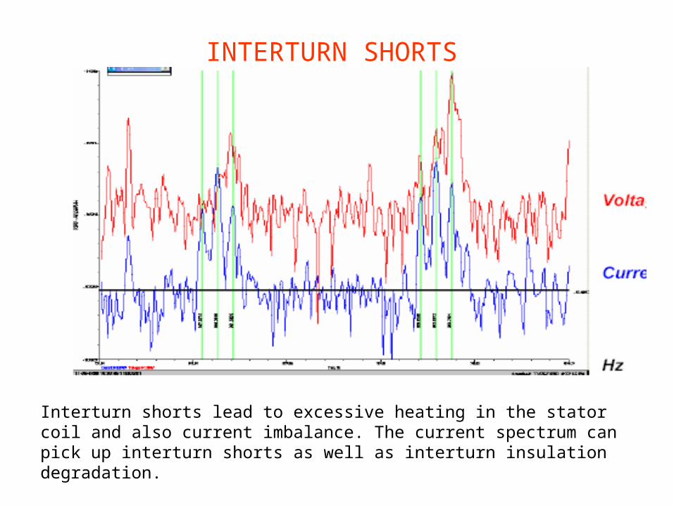
Interturn shorts lead to excessive heating in the stator coil and also current imbalance. The current spectrum can pick up interturn shorts as well as interturn insulation degradation.
INTERTURN SHORTS


