1 Monitoring System for Safety of Fishing Vessels Subjected to Waves Susana M. Varela, Carlos Guedes Soares, Tiago Santos Instituto Superior Técnico Abstract This paper describes and implements a monitoring and decision support system to evaluate the safety of fishing vessels subjected to waves. In order to develop the system, the Portuguese fleet and fishing methods had to be identified. As a result, it was concluded that although capsizing is the most serious hazard due to the loss of human lives, operational hazards are the most common ones. Thus, capsize mechanisms and environmental hazards were studied. The system architecture is described. The system is composed by a load monitoring module, a static stability analysis module and wave safety analysis module. The load monitoring module allows inputting the load conditions. The static stability analysis module computes the Torremolinos Convention Criteria for fishing vessels, the weather criteria and the IMO Severe Wind and Rolling Criteria. The wave safety analysis module implements the IMO-MSC(2007) guidelines and displays the critical speeds for environmental hazards on a polar diagram. The system was implements into the SM-SEPEO application which was tested for the load conditions defined by the Torremolinos convention Criteria. The application demonstrates that it is possible to implement the concept of monitoring and decision support to evaluate the safety of fishing vessels subjected to waves using low cost equipment. Introduction It is difficult to isolate engineering problems from the issue of safety since every human endeavor has an element of hazard or risk. Apparently the need for safety measures is influenced by the existence of such hazards or risks. In this respect fishing vessels are no exception in the sense that fishing vessels´ hazards are related with the environmental conditions and with the fishing methods employed. Portuguese fleet has continuously decreased in number of vessels and volume of catch since 20 years ago. It consists now of less than 1000 vessels of witch over 9000 are smaller then 12 m in length. Most of the vessels larger than 12 m are netters and longliners, followed by purse seiners and trawlers. Most of these vessels operate in Portuguese waters next to mainland. Trawlers face hazards such as coming fast, which is dangerous in heavy seas if breaking out is attempted, and bag lifting, especially if the trawl is filled with stones and mud. Handling the trawl doors is more of a personal danger. Potting involves great personal dangers and may cause capsize of the vessel if the anchor or pots became fouled in the seabed or if an excessive number of gears are carried on deck. Netting is only a problem if an excessive number of nets are carried or if the net bins became filled with water. Purse seiners are vulnerable to capsize if an excessive weight of fish is in the net, if sea water in the hold causes the fish to become fluid and shift or excessive fish load is on deck. Longlining may involve the danger of water inside the shelterdeck in case of heavy seas. So, the operational hazards can be categorized and
Transcript
1
Monitoring System for Safety of Fishing Vessels Subjected to
Waves
Susana M. Varela, Carlos Guedes Soares, Tiago Santos
Instituto Superior Técnico
Abstract
This paper describes and implements a monitoring and decision support system to evaluate the
safety of fishing vessels subjected to waves. In order to develop the system, the Portuguese
fleet and fishing methods had to be identified. As a result, it was concluded that although
capsizing is the most serious hazard due to the loss of human lives, operational hazards are the
most common ones. Thus, capsize mechanisms and environmental hazards were studied. The
system architecture is described. The system is composed by a load monitoring module, a static
stability analysis module and wave safety analysis module. The load monitoring module allows
inputting the load conditions. The static stability analysis module computes the Torremolinos
Convention Criteria for fishing vessels, the weather criteria and the IMO Severe Wind and
Rolling Criteria. The wave safety analysis module implements the IMO-MSC(2007) guidelines
and displays the critical speeds for environmental hazards on a polar diagram. The system was
implements into the SM-SEPEO application which was tested for the load conditions defined by
the Torremolinos convention Criteria. The application demonstrates that it is possible to
implement the concept of monitoring and decision support to evaluate the safety of fishing
vessels subjected to waves using low cost equipment.
Introduction
It is difficult to isolate engineering problems from the issue of safety since every human
endeavor has an element of hazard or risk. Apparently the need for safety measures is
influenced by the existence of such hazards or risks. In this respect fishing vessels are no
exception in the sense that fishing vessels´ hazards are related with the environmental
conditions and with the fishing methods employed.
Portuguese fleet has continuously decreased in number of vessels and volume of catch since
20 years ago. It consists now of less than 1000 vessels of witch over 9000 are smaller then 12
m in length. Most of the vessels larger than 12 m are netters and longliners, followed by purse
seiners and trawlers. Most of these vessels operate in Portuguese waters next to mainland.
Trawlers face hazards such as coming fast, which is dangerous in heavy seas if breaking out is
attempted, and bag lifting, especially if the trawl is filled with stones and mud. Handling the trawl
doors is more of a personal danger. Potting involves great personal dangers and may cause
capsize of the vessel if the anchor or pots became fouled in the seabed or if an excessive
number of gears are carried on deck. Netting is only a problem if an excessive number of nets
are carried or if the net bins became filled with water. Purse seiners are vulnerable to capsize if
an excessive weight of fish is in the net, if sea water in the hold causes the fish to become fluid
and shift or excessive fish load is on deck. Longlining may involve the danger of water inside
the shelterdeck in case of heavy seas. So, the operational hazards can be categorized and
2
include: handling the gear, boarding the catch, abnormal loads, coming fast, freeing fastened
gear, overloading the boat, modifying the gear or the boat. Environmental hazards include wind
heeling, stability on wave, breaking wave, rolling in waves, icing and flooding. Wolfson (2004)
investigation of fishing vessels accidents shows that operational mistakes were the major factor
in these accidents; however capsizing is the most serious hazard due to the loss of human
lives, Antão and Guedes Soares(2004).
Experimental and theoretical calculations made by De Kat (1989), Umeda (1994) and Adee
(1986) permitted divide capsizing modes into the following six categories: pure loss of stability,
breaking wave, synchronous waves, low cycle resonance, broaching. Pure loss of stability
occurs when the righting arm decreases to the point that there is not sufficient restoring energy
in the vessel to upright itself. The essential prerequisite for this to occur is a ship speed nearly
or equal to de wave speed so that the ship remains almost stationary relative to wave crest for a
sufficient length of time to capsize. This usually occurs in a following sea at high speed. On
breaking wave, two modes were identified: the hull is balanced on the wave, looses water plane
inertia and capsizes, and the wave overwhelms the bulwarks and floods the decks producing a
roll moment grater then the restoring moment leading the vessel to capsize. For the case of
Synchronous waves the vessel is hit by synchronous waves causing progressively large roll
angles leading to capsize. Low cycle resonance can be recognized by the frequency of roll
motion and occurs when the encounter frequency is nearly equal to twice the roll nature
frequency in following seas. Broaching implies the loss of directional control and occurs when
the vessel speed is close to the phase of the wave. The ship is then forced to move along the
wave so that it becames directionally very unstable and may capsize. As seen from the above
capsizing modes, there are three critical conditions for inducing ship instabilities: wave speed
equal ship speed in following seas, encounter frequency equal to twice the roll natural
frequency and encounter frequency equal to roll natural frequency.
Regarding guidance for safety in following and quartering seas, IMO issued MSC Circ 707 in
1995, which was superseded by Circ 1228 in 2007. The Guidance in this document can form
the basis for a decision making system.
According to these guidance, Benedict et al. (2006) developed a simplified but robust method
for the on board calculation, based on the comparison of the ships natural rolling period and the
period of the wave encounter to prepare a polar diagram for synchronous and parametric
resonance and other wave effects from basic data of the ship and the sea state, even by
manual calculation. A computer program ARROW-Avoidance of Roll Resonance and Wave
impact was developed to display the potential dangerous conditions of rolling resonance or
other high wave impacts on ships due to specific wave encounter situations.
Previous studies were made. Köse et al.(1995) describes an intelligent monitoring and advisory
system for vessel safety. This system uses environmental information obtained from a number
of sensors and proposes corrective action based on a rule-base derived from human expertise,
experiments, and theoretical research. The architecture of the monitoring and advisory system
is based on the fuzzy logic using capsize modes of a ship. The results of the simulations of
3
various sea conditions leading to capsize and the vessel response to the corrective action
suggested by the advisory system shows the feasibility of such system. In 1982, a micro-
computer based capsize alarm system was developed by Koyama et al. (1982). In this system a
pendulum was used to measure ship motions. Mean period and root mean square roll angle
were used to assess safety of the vessel. As a result of an inadequate pendulum system, the
results were not very reliable at high speeds.
Today, improvements in computer technology and the low prices of measurements equipments
facilitate the integration of a safety monitoring system in fishing vessels. The monitoring and
decision support system to evaluate the safety of fishing vessels subjected to waves was
implemented on the computer application, SM-SEPEO, based on the following requirements:
the system should measure minimum amount of data, the system should not interfere with the
operation of the ship.
Description of effects and methods considered
As basis for implementing the monitoring and decision support system to evaluate the safety of
fishing vessels subjected to waves, the guidance for safety in following and quartering seas,
IMO issued MSC Circ 707 in 1995, which was superseded by Circ 1228 in 2007, the 1977
Torremolinos Convention and its 1993 protocol, were taken into consideration.
From the IMO(1995) and IMO(2007), the principal dangers were considered: surf-riding and
broaching, synchronous rolling motion, parametric rolling motion, reduction of stability riding on
the crest in the wave groups. The Surf-riding and broaching occurs when a vessel is situated on
a steep forefront of high wave in following and quartering sea condition. As consequence, the
vessel can be accelerated to ride on the wave; this is known as surf-riding. When the vessel is
surf-riding, the so called broaching phenomenon may occur, which endangers the vessel to
capsize as the result of sudden change of vessel’s heading and unexpected large heeling.
The synchronous rolling motion occurs when the natural rolling period of a vessel coincides with
the encounter wave period leading to large rolling motions. In case of navigation in following
and quartering seas this may happen when the transverse stability of the vessel is marginal and
therefore the natural roll period becomes longer.
The Parametric rolling motion is an unstable and large amplitude roll motion that takes place if
the encounter wave period is approximately equal to half of the natural roll period of the vessel.
This type of rolling can occur in head and bow seas where the encounter wave period becomes
short. In following and quartering seas, this can occur particularly when the initial metacentric
height is small and the natural period is very long.
Reduction of stability riding on the crest in the wave groups occurs when the vessel speed
component in the wave direction is nearly equal to the wave group velocity, which is half of the
phase velocity of the dominant wave components. If such situation occurs, the vessel is
attacked successively by high waves. The expectable maximum wave height of the successive
waves can reach almost twice the observed wave height of the sea state concerned.
4
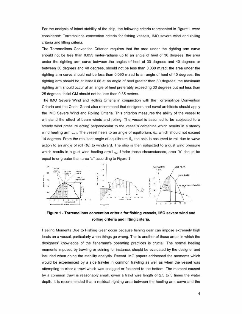
For the analysis of intact stability of the ship, the following criteria represented in Figure 1 were
considered: Torremolinos convention criteria for fishing vessels, IMO severe wind and rolling
criteria and lifting criteria.
The Torremolinos Convention Criterion requires that the area under the righting arm curve
should not be less than 0.055 meter-radians up to an angle of heel of 30 degrees; the area
under the righting arm curve between the angles of heel of 30 degrees and 40 degrees or
between 30 degrees and 40 degrees, should not be less than 0.030 m.rad; the area under the
righting arm curve should not be less than 0.090 m.rad to an angle of heel of 40 degrees; the
righting arm should be at least 0.66 at an angle of heel greater than 30 degrees; the maximum
righting arm should occur at an angle of heel preferably exceeding 30 degrees but not less than
25 degrees; initial GM should not be less than 0.35 meters.
The IMO Severe Wind and Rolling Criteria in conjunction with the Torremolinos Convention
Criteria and the Coast Guard also recommend that designers and naval architects should apply
the IMO Severe Wind and Rolling Criteria. This criterion measures the ability of the vessel to
withstand the effect of beam winds and rolling. The vessel is assumed to be subjected to a
steady wind pressure acting perpendicular to the vessel's centerline which results in a steady
wind heeling arm Lw1. The vessel heels to an angle of equilibrium, θ0, which should not exceed
14 degrees. From the resultant angle of equilibrium θ0, the ship is assumed to roll due to wave
action to an angle of roll (θ1) to windward. The ship is then subjected to a gust wind pressure
which results in a gust wind heeling arm Lw2. Under these circumstances, area “b” should be
equal to or greater than area “a” according to Figure 1.
Figure 1 - Torremolinos convention criteria for fishing vessels, IMO severe wind and
rolling criteria and lifting criteria.
Heeling Moments Due to Fishing Gear occur because fishing gear can impose extremely high
loads on a vessel, particularly when things go wrong. This is another of those areas in which the
designers’ knowledge of the fisherman's operating practices is crucial. The normal heeling
moments imposed by trawling or seining for instance, should be evaluated by the designer and
included when doing the stability analysis. Recent IMO papers addressed the moments which
would be experienced by a side trawler in common trawling as well as when the vessel was
attempting to clear a trawl which was snagged or fastened to the bottom. The moment caused
by a common trawl is reasonably small, given a trawl wire length of 2.5 to 3 times the water
depth. It is recommended that a residual righting area between the heeling arm curve and the
5
righting arm curve should be at least 15 foot-degrees to the angle of maximum righting arm. In
addition, the static angle of heel should not exceed 10 degrees. The heeling moment is the
maximum generated based on the allowed combinations of hook load and radius. The heeling
arm curve is defined by HA = Maximum heeling moment x cosine θ / ∆. In calculating the
righting arm curve, the designer must remember to account for the increase in VCG due to the
lifting of the weight.
Out line the System
The system SM-SEPEO was developed using a modular dependent architecture, composed by
a load monitoring module, a static stability analysis module and wave safety analysis module.
The load monitoring module allows inputting the load conditions. The static stability analysis
module computes the Torremolinos Convention Criteria for fishing vessels, the weather criteria
and the IMO Severe Wind and Rolling Criteria. The wave safety analysis module implements
the IMO-MSC (2007) guidelines and displays the critical speeds for environmental hazards on a
polar diagram.
Figure 2 –Layout for monitoring and decision support system to evaluate the safety of
fishing vessels subjected to waves – application SM-SEPEO.
Development of Monitoring Load Condition Module
The load monitoring module allows inputting the load conditions. The data input and storage
into the monitoring load condition module is done through ASCII text files, as shown in Figure
3. For this purpose, four different files are considered containing the following information: file
with characteristics of fishing vessel, file with weight distribution, file with loading percentage on
tanks, file with historic of sensor measurements. The second and the third type of files are
simultaneously input and output files in the sense that the system saves the changes made by
the user in these files. The fields corresponding to the identification of the vessel are not
6
editable by the user since this data is read from the file with the characteristics of fishing
vessel. Only by changing this file is possible to update the ship characteristics.
Figure 3 – Layout of the monitoring load condition module and respective screen.
The user is allowed to change the weights and their corresponding locations, the tanks loading
percentage, and to indicate if water on deck exists or if lifting operations are running. The
longitudinal and transversal inclinometer measurement values, the free board and winch
lifting weight are computed randomly by an internal function. Only the maximum winch lifting
weight is validated by this module. However this validation only alerts for the situation,
allowing the system to continue with the calculations.
Development of Static Stability Analysis Module
The static stability analysis module computes the Torremolinos Convention Criteria for fishing
vessels, the weather criteria and the IMO Severe Wind and Rolling Criteria. According to the
requirements specification this module displays the parameters computed by the system,
which define the stability of the ship. The ship is graphically represented as well as trim and
heeling lines, the tanks loading percentage as shown in Figure 4.
Figure 4 - Layout of the static stability analysis module and respective screen.
7
When the mentioned criteria are not full field with the inputted loading condition, visual alerts
are immediately displayed in order to call user attention for this situation (Figure 4).
Development of Wave Safety Analysis Module
The wave safety analysis module implements the IMO-MSC(1995) and MSC(2007) guidelines
displaying the critical speeds for environmental hazards on a polar diagram. The interface is
contains three different frames: the input data area, the dangerous phenomena analysis area,
and the polar diagram representation area.
The input data area allows the user to define the ship navigational parameters namely the
forward speed, the heading and the rolling period. The sea state, which in this scope is
characterized by the main propagation direction, the significant wave height and by the wave
period, is also inputted by the user in this area. These values are used to compute the
encounter period and angle, and the relation between the rolling and the encounter periods,
both displayed in non-editable fields.
The dangerous hazards are displayed separately in a second frame. For each phenomenon, the
critical values of the forward speed, encounter angle and relation between rolling and encounter
periods, are displayed. These values indicate the limits in which the phenomenon occurs. The
polar diagram displays graphically the heading and wave main direction of propagation angles,
and the forward speed of the ship. The following values are displayed: wave main direction of
propagation represented by an arrow at the diagram border, ship heading represented by a
sketch of the ship at the origin of the diagram, the forward speed vector also located at the
origin of the diagram, hatched areas where dangerous phenomena occur. The representation
of these phenomena in the polar diagram allows the user to be aware if ship is near or inside a
dangerous zone. For the last case a message with corrective measures is displayed.
Figure 5 -- Layout of the wave safety analysis module module and respective screen.
The rolling period is given by the following expression:
GMtg
ArTr
∇
+∆=
ρπ 44
2
442
(Eq. 1)
8
where r44 is the rolling rotation radius measured in a parallel axis to a longitudinal axis that
crosses the ship’s centre of gravity and for the present case r44=0.35B; A44 is the roll added
moment and is equal to a44L, where a44 is the roll added mass a44=0.04AMSB2; AMS is the
mid ship section area, where AMS=0.97BT; ρ is density of sea water (ρ=1.025); g is the
acceleration of gravity (g=9.81 m/s2); GMt is the transverse metacentric height and ∇ is the
displaced volume of the ship.
Encounter period is calculated by the expression:
)gTwcosV2(1
TwTe
βπ+=
(Eq. 2)
where TW is the wave period, TW=0.8 λ where λ is wave length; V is de ship speed; β is
the encounter angle where: °−ψ−ψ=β 1800 Where Ψ is the ships course and ψ0 is the
wave heading angle.
Table 1 summarizes the effects and formulas for calculation of a basic polar diagram values.
Phenomena Direction/Sector/Area Equations to calculate the speed values as basis for the
diagram elements
1.Synchronous rolling motion
stripe segments over diagram; All directions possible
1. for Te = Tr/0.8
−
π= 1
8.0Tr
Tw
2
gTwV 8.0
2.for Te = Tr/1.1
−
π= 1
1.1Tr
Tw
2
gTwV 1.1
2.Parametric rolling motion
Segment for direct head and stern waves conditions +/- 30º
2. for Te = Tr/0.8
−
π= 1
8.1Tr
Tw
2
gTwV 8.1
2. for Te = Tr/2.1
−
π= 1
1.2Tr
Tw
2
gTwV 1.2
3.Reduction os stability riding on the cresat of wave groups
Segment for direct following and quartering seas +/- 45º
Tw8.0V 8.0,wavegroup =
Tw0.2V 0.2,wavegroup =
4. Suf-riding and Broaching
Segment for direct following and quartering seas +/- 45º
L4.1V 4.1,surf =
L8.1V 8.1,surf =
L0.3V 0.3,surf =
Table 1 – Summary of effects and formulas for calculation of a basic polar diagram values.
Results
The tests performed to demonstrate the main functionalities of the system were based on the
cargo conditions stated by the Torremolinos convention. The following recommendations for the
cargo conditions were applied: leaving the fishing zone with fuel tanks, food and ice completely
loaded, and fishing gear; leaving the fishing zone with maximum fishing cargo; port arrival with
maximum fishing cargo and 10% of food and fuel; port arrival with 10% of food and fuel, and
with 20% of fishing maximum cargo (the minimum cargo considered).
9
The following parameters were constant for all the tests in the wave safety analysis: wave
direction of propagation (10 degrees), wave height (3 m), wave period (12 s), forward speed (20
knots), heading (120 degrees). As a result, the influence of the load variation in the safety of the
ship on the wave can be evaluated as shown in Figure 6.
Figure 6 – Results of 2nd and 4
th load conditions of the Torremolinos convention.
Conclusion
The presented study describes and implements a monitoring and decision support system to
evaluate the safety of fishing vessels subjected to waves. The static stability analysis module
computes the Torremolinos Convention Criteria for fishing vessels, the weather criteria and the
IMO Severe Wind and Rolling Criteria. The wave safety analysis module implements the IMO-
MSC (2007) guidelines and displays the critical speeds for environmental hazards on a polar
diagram. The application demonstrates that it is possible to implement the concept of
monitoring and decision support to evaluate the safety of fishing vessels subjected to waves
using low cost equipment.
Reference
Adee, B.H. e Winandy,D. (1986), “Fishing Vessels Dynamics and Stability”, in Star Symposium
Spring Meeting, Society of Naval Architects and Marine Engineers (SNAME), Portland Oregon,
USA.
10
Antão, P., Guedes Soares, C.(2004), “Análise de Acidentes de Navios de Pesca Portugueses”,
in As Actividades Marítimas e a Engenharia, C.Guedes Soares e V. Gonçalves de Brito (Eds),
Edições Salamandra, Lisboa.
Benedict, K.,Kirchhoff, M.,Baldauf, M.(2006), “Decision Suport for Avoiding Resonance and
Wave Impact for Ship Operation in Heavy Seas”, Safety and Reliability for Managing Risk,
Francis & Taylor.
De Kat, J. e Paulling J.R. (1989), “The Simulation of Ship Motions and Capsizing in Severe
Seas”, Society of Naval Architects and Marine Engineers (SNAME) – Transactions, 97: p. 139–
168.
IMO-MSC (1995), “MSC Circ. 707 – Revised Guidance to the Master for Avoiding Dangerous
Situations in Adverse Weather and Sea Conditions”.
IMO-MSC (2007), “MSC Circ. 1228 – Guidance to the Master for Avoiding Dangerous Situations
in Adverse Weather and Sea Conditions”.
MADRP- DGPA (2006), “Plano Nacional Estratégico para a Pesca (2007-2013)”.
Köse, E., Gosine, Raymond G., Dunwoody, A. Bruce, Calisal, S. M., (1995), “An Expert System
for Monitoring Dynamic Stability of Small Craft”, IEEE Journal of Oceanic Engineering. Vol 20,
nº1.
Koyama, T.(1982), “On a Micro-Computer Based Capesize Alarm System”, Second Int. Conf. of
Stability of Ship and Ocean Vehicles, Tokyo.
Umeda, N. and Renilson, M.R., (1994) “Broaching of a Fishing Vessel in Following and
Quartering Seas – Non Linear Dynamical Systems Approach” STAB’94, USA
Woffson Unit (2004), “Loading Guidance of Fishing Vessels Less then 12m Registered Length –
Phase 1”, Research Project 529, Maritime and Coast Guard Agency.