26
Monitoring, Mitigating and Troubleshooting FCC Catalyst Losses Bob Ludolph CatCracking.com League City, TX - April 12-16, 2010
Monitoring, Mitigating and g g gTroubleshooting FCC Catalyst Losses
Bob Ludolph
CatCracking.com League City, TX - April 12-16, 2010
Presentation OutlinePresentation Outline• Loss Precursors & Warning Signsg g
• Catalyst Monitoring
• Equipment Contributions
• Troubleshooting Loss Causes
• Mitigation & Pre-Entry Activities
2
Catalyst LossP d W i SiPrecursors and Warning Signs
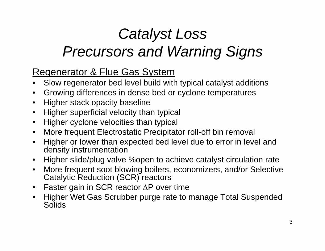
Regenerator & Flue Gas System• Slow regenerator bed level build with typical catalyst additions• Growing differences in dense bed or cyclone temperatures• Higher stack opacity baseline
Hi h fi i l l it th t i l• Higher superficial velocity than typical• Higher cyclone velocities than typical• More frequent Electrostatic Precipitator roll-off bin removal• Higher or lower than expected bed level due to error in level and• Higher or lower than expected bed level due to error in level and
density instrumentation• Higher slide/plug valve %open to achieve catalyst circulation rate• More frequent soot blowing boilers, economizers, and/or Selective q g , ,
Catalytic Reduction (SCR) reactors• Faster gain in SCR reactor ΔP over time • Higher Wet Gas Scrubber purge rate to manage Total Suspended
SolidsSolids
3
Catalyst LossP d W i SiPrecursors and Warning Signs
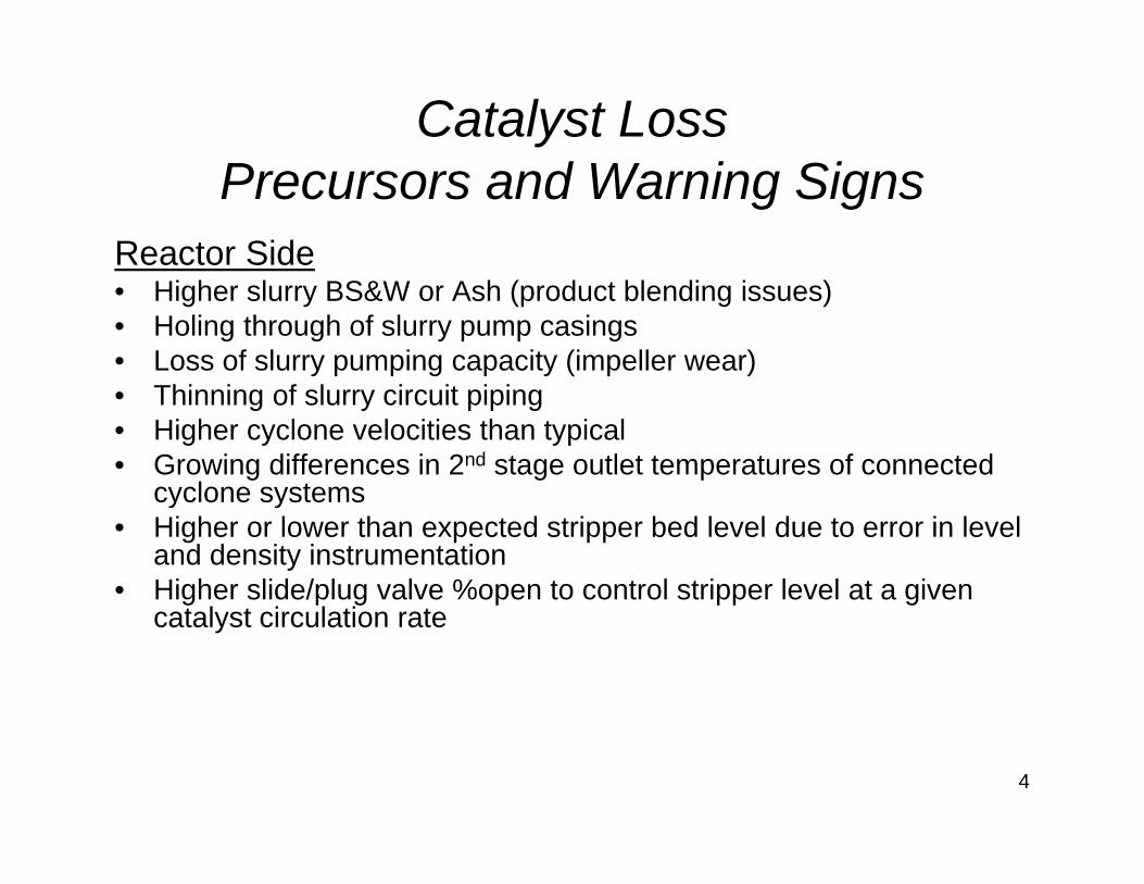
Reactor Side• Higher slurry BS&W or Ash (product blending issues) • Holing through of slurry pump casings• Loss of slurry pumping capacity (impeller wear)
Thi i f l i it i i• Thinning of slurry circuit piping• Higher cyclone velocities than typical• Growing differences in 2nd stage outlet temperatures of connected
cyclone systemscyclone systems• Higher or lower than expected stripper bed level due to error in level
and density instrumentation• Higher slide/plug valve %open to control stripper level at a given
t l t i l ti tcatalyst circulation rate
4
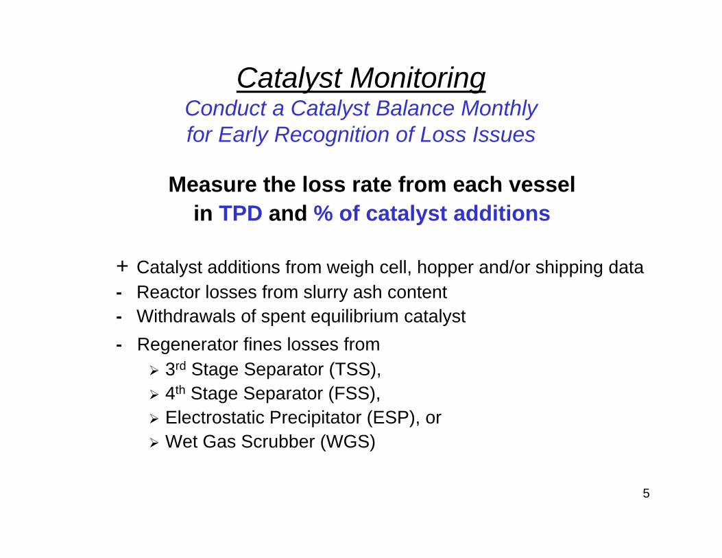
Catalyst MonitoringC d t C t l t B l M thlConduct a Catalyst Balance Monthlyfor Early Recognition of Loss Issues
Measure the loss rate from each vessel in TPD and % of catalyst additions
+ Catalyst additions from weigh cell, hopper and/or shipping data- Reactor losses from slurry ash content
Withdrawals of spent equilibrium catalyst- Withdrawals of spent equilibrium catalyst- Regenerator fines losses from
3rd Stage Separator (TSS),4th Stage Separator (FSS),Electrostatic Precipitator (ESP), or Wet Gas Scrubber (WGS)
5
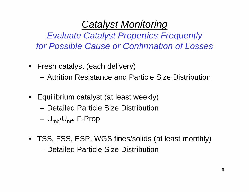
Catalyst MonitoringEvaluate Catalyst Properties FrequentlyEvaluate Catalyst Properties Frequently
for Possible Cause or Confirmation of Losses
• Fresh catalyst (each delivery)– Attrition Resistance and Particle Size Distribution
• Equilibrium catalyst (at least weekly)– Detailed Particle Size Distribution– Detailed Particle Size Distribution – Umb/Umf, F-Prop
• TSS, FSS, ESP, WGS fines/solids (at least monthly)– Detailed Particle Size Distribution
6
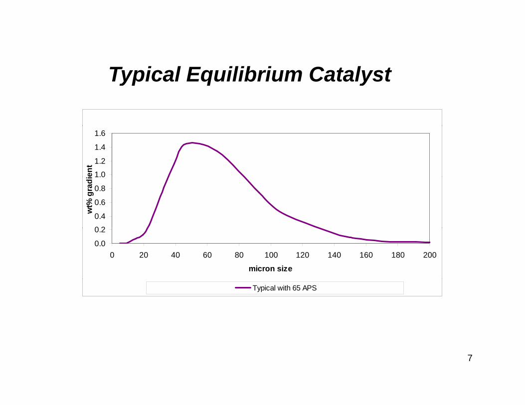
Typical Equilibrium CatalystTypical Equilibrium Catalyst
1.0
1.2
1.4
1.6
ent
0 2
0.4
0.6
0.8
1.0
wt%
gra
di
0.0
0.2
0 20 40 60 80 100 120 140 160 180 200
micron size
Typical with 65 APS
7
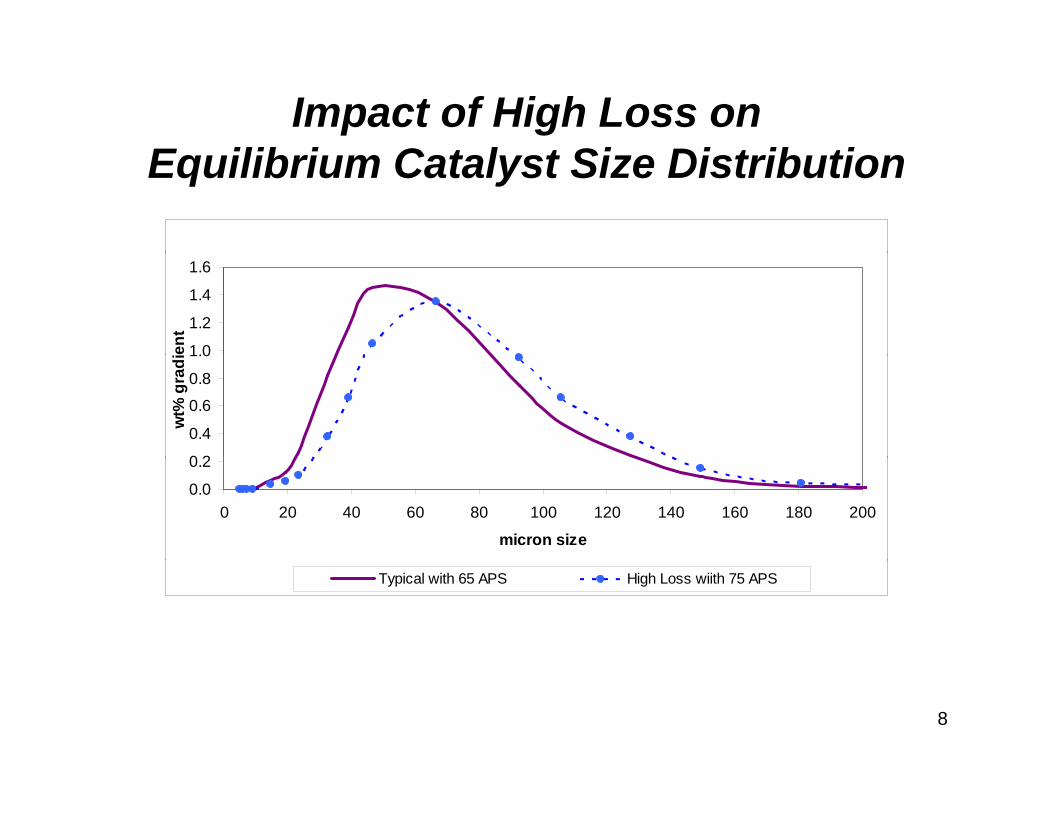
Impact of High Loss onE ilib i C t l t Si Di t ib tiEquilibrium Catalyst Size Distribution
1.0
1.2
1.4
1.6
ient
0 2
0.4
0.6
0.8
1.0
wt%
gra
di
0.0
0.2
0 20 40 60 80 100 120 140 160 180 200
micron size
Typical with 65 APS High Loss wiith 75 APS
8
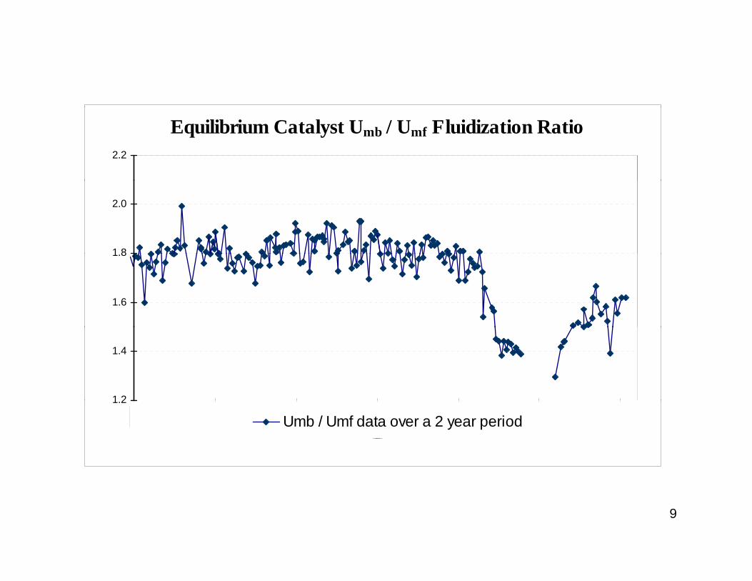
Equilibrium Catalyst Umb / Umf Fluidization Ratio2.2
1 8
2.0
1.6
1.8
1 2
1.4
1.2
Umb / Umf data over a 2 year period
9
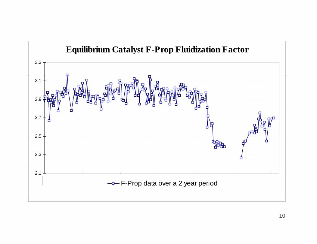
Equilibrium Catalyst F-Prop Fluidization Factor3.3
2.9
3.1
2.5
2.7
2.3
2.5
2.1
F-Prop data over a 2 year period
10
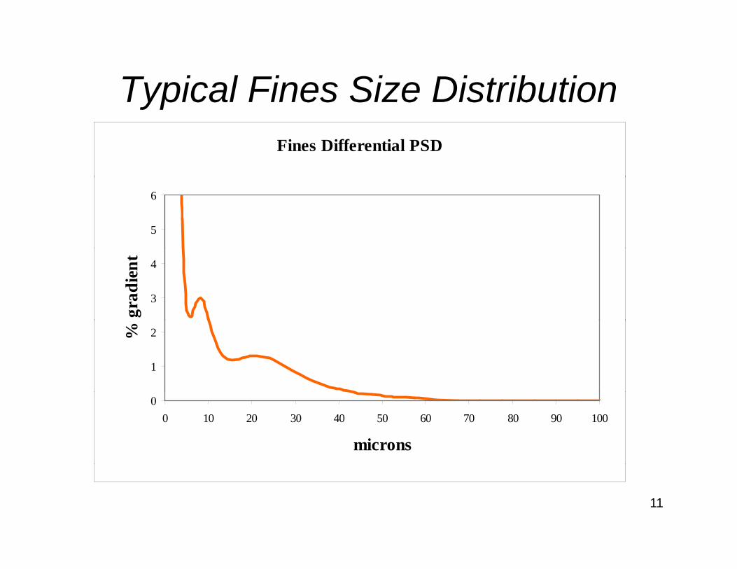
Typical Fines Size DistributionypFines Differential PSD
5
6
3
4
grad
ient
1
2%
00 10 20 30 40 50 60 70 80 90 100
microns
11
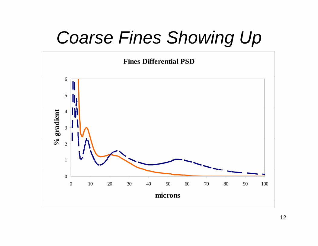
Coarse Fines Showing Upg pFines Differential PSD
5
6
3
4
gra
dien
t
1
2%
00 10 20 30 40 50 60 70 80 90 100
microns
12
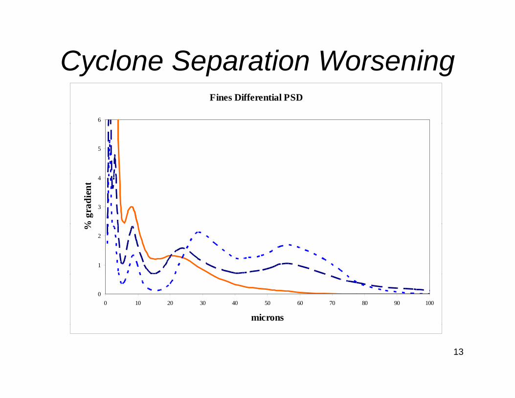
Cyclone Separation Worseningy p gFines Differential PSD
6
5
3
4
% g
radi
ent
1
2
%
00 10 20 30 40 50 60 70 80 90 100
microns
13
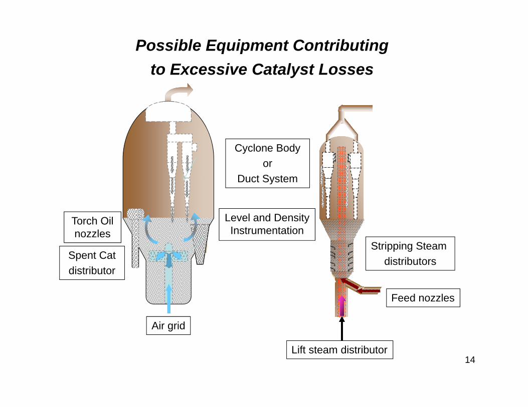
Possible Equipment Contributingto Excessive Catalyst Lossesy
Cyclone Bodyor
Duct SystemDuct System
Level and Density Instrumentation
Torch Oil
Stripping Steam distributorsSpent Cat
distributor
Instrumentationnozzles
Feed nozzles
Air grid
Lift steam distributor14
Equipment Investigations
Has the loss been gradual or sudden?
What excursions, shutdowns, startups, or unusual operations have occurred?
15
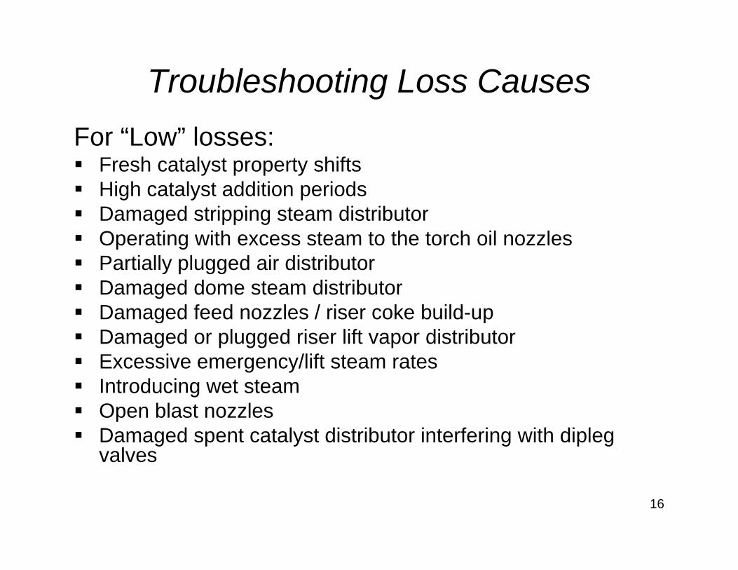
Troubleshooting Loss CausesFor “Low” losses:
Fresh catalyst property shiftsHigh catalyst addition periodsDamaged stripping steam distributorOperating with excess steam to the torch oil nozzlesp gPartially plugged air distributorDamaged dome steam distributor Damaged feed nozzles / riser coke build-upg pDamaged or plugged riser lift vapor distributorExcessive emergency/lift steam ratesIntroducing wet steamt oduc g et steaOpen blast nozzlesDamaged spent catalyst distributor interfering with dipleg valves
16
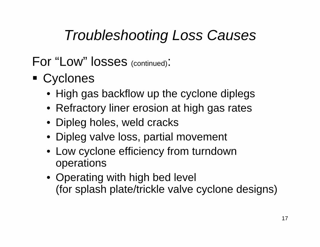
Troubleshooting Loss Causes
For “Low” losses (continued):CyclonesCyclones• High gas backflow up the cyclone diplegs• Refractory liner erosion at high gas rates• Refractory liner erosion at high gas rates• Dipleg holes, weld cracks• Dipleg valve loss partial movementDipleg valve loss, partial movement• Low cyclone efficiency from turndown
operations• Operating with high bed level
(for splash plate/trickle valve cyclone designs)
17
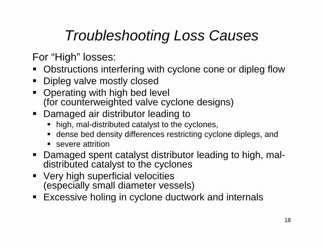
Troubleshooting Loss CausesFor “High” losses:
Obstructions interfering with cyclone cone or dipleg flowDi l l tl l dDipleg valve mostly closedOperating with high bed level(for counterweighted valve cyclone designs)Damaged air distributor leading to
high, mal-distributed catalyst to the cyclones,dense bed density differences restricting cyclone diplegs, andsevere attrition
Damaged spent catalyst distributor leading to high, mal-distributed catalyst to the cyclonesVery high superficial velocities (especially small diameter vessels) Excessive holing in cyclone ductwork and internals
18
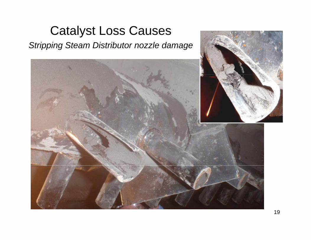
Catalyst Loss CausesStripping Steam Distributor nozzle damageStripping Steam Distributor nozzle damage
19
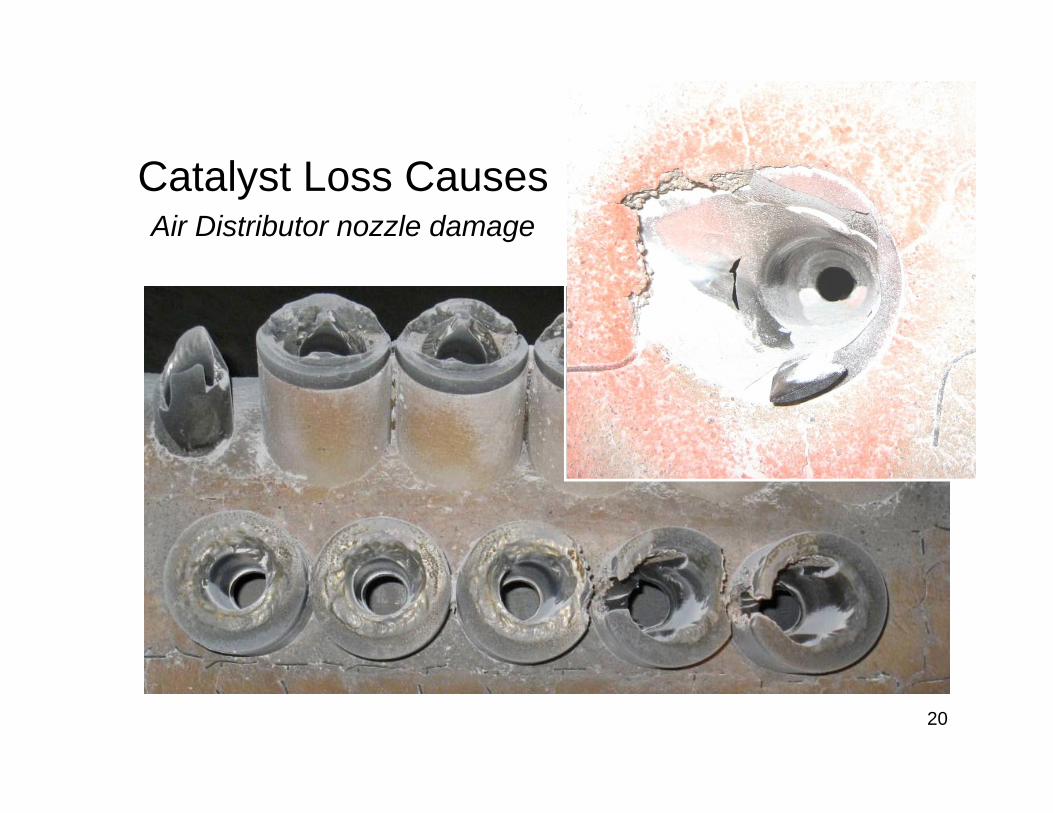
Catalyst Loss CausesAir Distributor nozzle damage
20
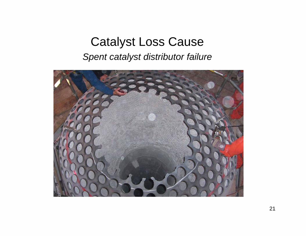
Catalyst Loss CauseCatalyst Loss CauseSpent catalyst distributor failure
21
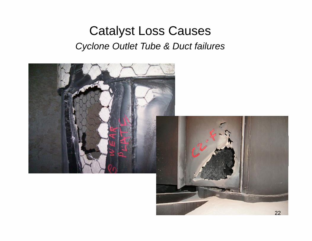
Catalyst Loss CausesCyclone Outlet Tube & Duct failuresCyclone Outlet Tube & Duct failures
22
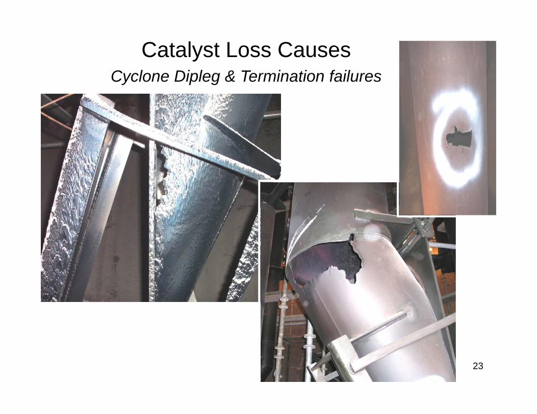
Catalyst Loss CausesCyclone Dipleg & Termination failuresCyclone Dipleg & Termination failures
23
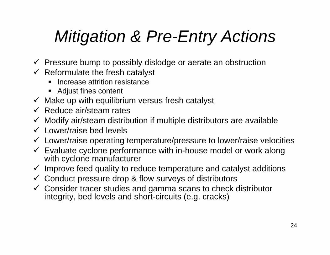
Mitigation & Pre-Entry ActionsPressure bump to possibly dislodge or aerate an obstructionReformulate the fresh catalyst
I tt iti i tIncrease attrition resistanceAdjust fines content
Make up with equilibrium versus fresh catalystReduce air/steam ratesReduce air/steam ratesModify air/steam distribution if multiple distributors are available Lower/raise bed levelsLower/raise operating temperature/pressure to lower/raise velocitiesp g p pEvaluate cyclone performance with in-house model or work along with cyclone manufacturerImprove feed quality to reduce temperature and catalyst additionsC d t d & fl f di t ib tConduct pressure drop & flow surveys of distributorsConsider tracer studies and gamma scans to check distributor integrity, bed levels and short-circuits (e.g. cracks)
24
Summaryy
It is important to track the catalyst loss rate from each vessel as well as measure the properties of the lost catalystp p y
The information enables the refiner to assess the operating condition of key equipment
and physical integrity of the inventory catalyst
Changes in inventory catalyst properties can ti l i t t l t fl idi tinegatively impact catalyst fluidization
and limit the capacity or upgrading capability of the unit
Early recognition of these changes will enable the refinerEarly recognition of these changes will enable the refinerto troubleshoot and develop quicker corrective action plans
for staying on-line and keeping operating costs down
25