Monogram: a Tube Phonostage for 78s Build this front-end based on the popular Cornet. By Jim Hagerman Many audiophiles still have collections of vintage 78s and other records pressed prior to 1955, when the industry consolidated on the RIAA equalization standard. While these records may not be of the highest quality or have the lowest noise floors, they do archive some of the best musical performances ever given. The problem is that most modern phonograph reproduction equipment is not up to the task of proper playback. First, you need a stylus of the correct shape and size to handle the larger grooves. Second, the electronics must support a variety of equalization settings to realize a flat frequency response. This project provides a solution to the latter – a monophonic vacuum tube-based phonograph preamplifier with six turnover frequencies and five cut settings, enough to adequately compensate virtually all known recordings. A completed unit can be done for about $300. Concept The Monogram is based on the Cornet phono stage circuit board (see Resources). It uses one channel to implement the phono section, and the other to create a linestage with volume control. Figure 1. Front view of completed project. The turnover frequencies are 100Hz, 200Hz, 300Hz, 400Hz, 500Hz, and 700Hz. Bass rolloff is fixed at 50Hz, not having much affect on sonic performance. The cut settings are 0dB, 5dB,
Transcript
Monogram: a Tube Phonostage for 78s Build this front-end based on the popular Cornet. By Jim Hagerman
Many audiophiles still have collections of vintage 78s and other records pressed prior to 1955, when the industry consolidated on the RIAA equalization standard. While these records may not be of the highest quality or have the lowest noise floors, they do archive some of the best musical performances ever given. The problem is that most modern phonograph reproduction equipment is not up to the task of proper playback. First, you need a stylus of the correct shape and size to handle the larger grooves. Second, the electronics must support a variety of equalization settings to realize a flat frequency response. This project provides a solution to the latter – a monophonic vacuum tube-based phonograph preamplifier with six turnover frequencies and five cut settings, enough to adequately compensate virtually all known recordings. A completed unit can be done for about $300. Concept The Monogram is based on the Cornet phono stage circuit board (see Resources). It uses one channel to implement the phono section, and the other to create a linestage with volume control.
Figure 1. Front view of completed project. The turnover frequencies are 100Hz, 200Hz, 300Hz, 400Hz, 500Hz, and 700Hz. Bass rolloff is fixed at 50Hz, not having much affect on sonic performance. The cut settings are 0dB, 5dB,
11dB, 13.7dB, and 16dB, corresponding to time constants of 0 �� �������� ���� �� � �� ������� ���������������������������������������������������������������������������
Figure 2. Rear view showing connections. Circuit Design The power supply employs tube rectification, which provides an inherent time delay for the high voltage circuits, thereby relieving the sensitive preamp tubes from cathode stripping. The heater supply uses full-wave rectification and passive RC filtering to achieve a low ripple 6.3Vdc. All amplification stages use simple single-ended class-A circuits. The first stage consists of a 12AX7 with both sections wired in parallel for lower noise. Equalization is performed by passive RC filter sections, with values selected by rotary switches. This non-feedback topology arguably provides improved sonics. The second and third stages use 12AU7s for medium gain and high output drive capability. Active current sinks are used for the cathode followers instead of the traditional pulldown resistor for better dynamics. The phase of the output has inverted polarity. Parts List In addition to the blank circuit board, the following table lists the components required to build the complete project as shown in Figure 1. Disclaimer: This project contains high voltages and should only be built by skilled and competent technicians!
Chassis The chassis is made from a standard folded aluminum 12x8x2 box. Optional wood sides can be added for a nicer appearance. Drill guides are provided in the manual (make sure printing is 1:1) for accurate measurement and placement of holes and other metalwork. This greatly simplifies construction and insures an accurate fit. The large holes are best cut using a punch, but a step-drill will also provide decent results. The supplied decal artwork can be used for silkscreening to label the controls. A cheaper approach is to print the decal onto laser label paper, which is then applied to the chassis. By spraying with a clear lacquer, a smudge-proof finish can be achieved.
q Using the drill guide, mark hole locations on the top of the chassis. q Similarly, use the decals to mark hole locations for the front and back. q Drill and punch all holes. q Use a file to cleanly shape the ac cord input connector slot. q Drill a pattern of 3/16” holes in the bottom cover for ventilation. q Use a 1/8” bit to drill holes in both bottom cover and chassis for mounting via #6 sheet
metal screws. q File down all burrs and edges. q Wash the chassis with dishsoap to eliminate oils and fingerprints. q Spray paint with a primer before applying a color coat. A hammertone finish works best. q Apply wood sides. q Insert the rubber grommets and ac power connector. q Connect a ground wire from the hole (#6 screw) between grommets to the Earth terminal
on ac input. q Mount the transformer with ac wires towards the outside. q Add power switch and LED. q Add RCA jacks and ground lug. q Add volume control. q Set position limiter to #6 on selection switch S2 and install. q Set limiter to #5 on S3 and install.
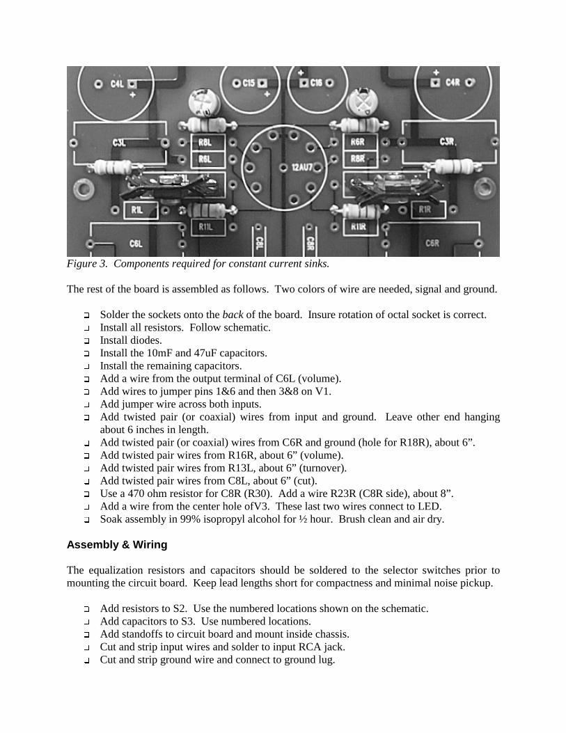
Circuit Board Build the constant current sinks first, since component locations are not shown on the circuit board’s silk screen. Use Figure 3 as a guide. The bottom two resistors are 220 ohm, others 910 ohm. Mount the transistors to heat sinks using #4 screws. Bend leads appropriately to insure proper fit and no short circuits.
q Solder parts in place.
Figure 3. Components required for constant current sinks. The rest of the board is assembled as follows. Two colors of wire are needed, signal and ground.
q Solder the sockets onto the back of the board. Insure rotation of octal socket is correct. q Install all resistors. Follow schematic. q Install diodes. q Install the 10mF and 47uF capacitors. q Install the remaining capacitors. q Add a wire from the output terminal of C6L (volume). q Add wires to jumper pins 1&6 and then 3&8 on V1. q Add jumper wire across both inputs. q Add twisted pair (or coaxial) wires from input and ground. Leave other end hanging
about 6 inches in length. q Add twisted pair (or coaxial) wires from C6R and ground (hole for R18R), about 6”. q Add twisted pair wires from R16R, about 6” (volume). q Add twisted pair wires from R13L, about 6” (turnover). q Add twisted pair wires from C8L, about 6” (cut). q Use a 470 ohm resistor for C8R (R30). Add a wire R23R (C8R side), about 8”. q Add a wire from the center hole ofV3. These last two wires connect to LED. q Soak assembly in 99% isopropyl alcohol for ½ hour. Brush clean and air dry.
Assembly & Wiring The equalization resistors and capacitors should be soldered to the selector switches prior to mounting the circuit board. Keep lead lengths short for compactness and minimal noise pickup.
q Add resistors to S2. Use the numbered locations shown on the schematic. q Add capacitors to S3. Use numbered locations. q Add standoffs to circuit board and mount inside chassis. q Cut and strip input wires and solder to input RCA jack. q Cut and strip ground wire and connect to ground lug.
q Connect wires to output RCA jack. q Connect wires from R13L to S2. Ground wire goes to center pin on switch. Solder other
wire to remaining leads of all six resistors. q Connect wires from C8L to S3. Ground wire goes to center pin. Signal wire goes to
remaining leads of all four capacitors. q Connect wires from R16R and C6L to volume pot. Center pin is signal lead of R16R.
Pin towards tranformer comes from C16L. q Connect remaining two wires to LED. Long lead goes to V3 (positive). q Add wire from LINE on ac connector to power switch. q Connect one black wire from transformer to power switch. q Connect other black wire to NEUTRAL on ac connector. q Solder secondary wires into their respective hole locations on circuit board.
Figure 3. Internal wiring. Assembly is complete. Now some testing is required. Install a fuse and vacuum tubes. Put on some safety glasses and fire it up. Check for smoke! If all went well and LED is on, voltages should settle near those specified on the schematic. Power down and add bottom cover and feet. Your Monogram is now complete.
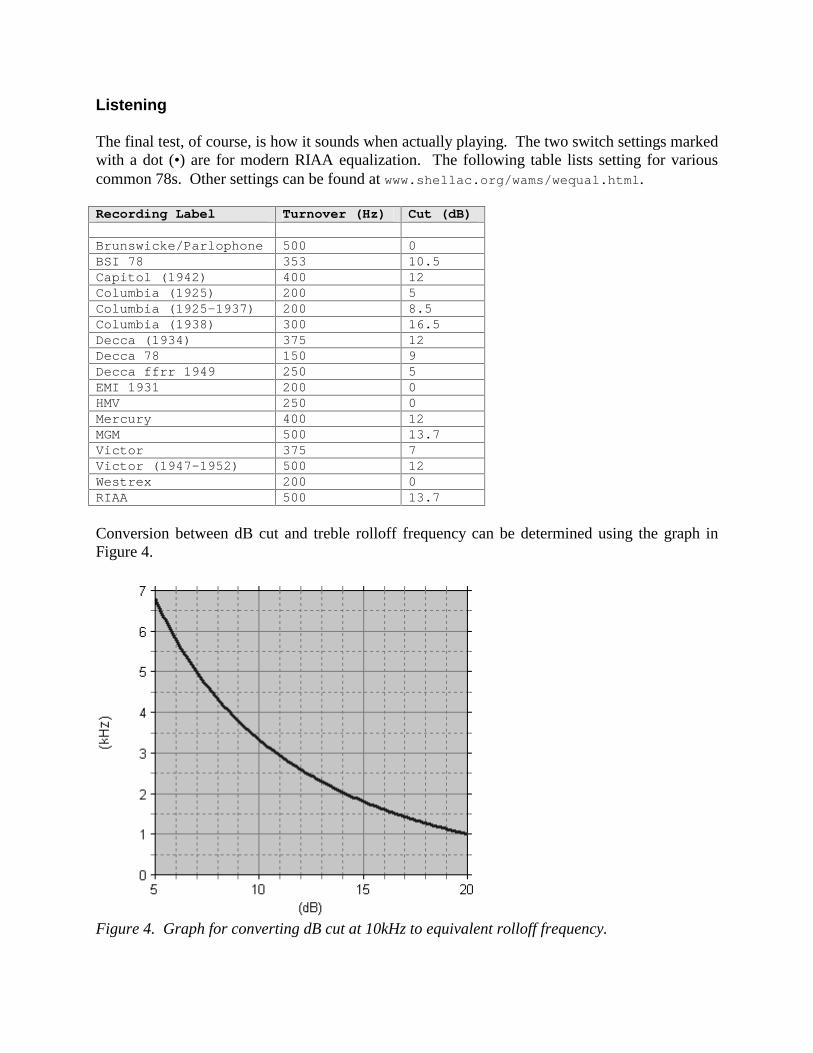
Listening The final test, of course, is how it sounds when actually playing. The two switch settings marked with a dot (•) are for modern RIAA equalization. The following table lists setting for various common 78s. Other settings can be found at www.shellac.org/wams/wequal.html. Recording Label Turnover (Hz) Cut (dB) Brunswicke/Parlophone 500 0 BSI 78 353 10.5 Capitol (1942) 400 12 Columbia (1925) 200 5 Columbia (1925-1937) 200 8.5 Columbia (1938) 300 16.5 Decca (1934) 375 12 Decca 78 150 9 Decca ffrr 1949 250 5 EMI 1931 200 0 HMV 250 0 Mercury 400 12 MGM 500 13.7 Victor 375 7 Victor (1947-1952) 500 12 Westrex 200 0 RIAA 500 13.7
Conversion between dB cut and treble rolloff frequency can be determined using the graph in Figure 4.
Figure 4. Graph for converting dB cut at 10kHz to equivalent rolloff frequency.
Resources The blank Cornet circuit board can be purchased from Hagerman Technology (www.hagtech.com). All other components are available from Mouser (www.mouser.com) and Antique Electronic Supply (www.tubesandmore.com). ABOUT THE AUTHOR Jim Hagerman owns Hagerman Technology LLC, a supplier of unique DIY half-kits and high-end audio products. He’s been designing analog circuits for 20 years.
Ø1.375 inØ1.125 in
Ø0.500 in
Ø0.187 in
Ø0.141 in
Ø0.141 in
Ø0.375 in Ø0.250 in Ø0.250 in
Ø0.312 in
1.250 in
1.500 in 1.750 in 1.750 in 2.500 in 2.125 in 1.750 in