47
CORPORATE OFFICES308 SPRINGHILL FARM ROADFORT MILL, SOUTH CAROLINA 29715
TELEPHONE (803)548-8500FAX (803)548-8599
DISTRIBUTOR CUSTOMER SERVICETOLL FREE 800-523-6572FAX (803)548-8594
LINEAR CUSTOMER SERVICETOLL FREE 800-462-3399FAX (215)781-9830
This product section has been excerpted from our fullProduct Reference Guide to reduce download time.Our complete Product Reference Guide is available inprint and on CD-ROM. To receive the full version,please contact your nearest INA Sales Office listed onthe last page of this file.
MONORAILGUIDANCE SYSTEMS
FOREWORD
ABMA American Bearing Manufacturers AssociationASTM American Society Of Testing And MaterialsDIN Deutsches Institut für Normung e.V.ISO International Standards Organization
Elges, Andrews and Corrotect are registered trademarks ofINA USA Corporation.Permaglide is a registered trademark and a product ofKOLBENSCHMIDT AG, Neckarsulm, also produced inGreensburg, Indiana, USA.All other products and company names are trademarks or registeredtrademarks of their respective companies.
ALL RIGHTS RESERVED
INA USA Corporation308 Springhill Farm RoadFort Mill, SC 29715
Reproduction of this publication in whole or in part without the expresswritten consent of INA USA Corporation is prohibited.
Although every effort has been made to ensure the accuracy of theinformation contained in this catalog, INA shall not be liable for anyomissions or errors. Purchasers should consult their own testing todetermine the suitability of any product for a particular purpose. In noevent shall INA be liable for any claims for damages based upon breachof warranty, breach of contract, negligence, strict liability in tort, or anyother legal theory.
INA USA Corporation reserves the right to make changes / revisions tospecifications contained herein without notice.
�Copyright 1999, 2000 INA USA Corporation
This publication was designed to serve as a quick refer-ence to the standard product series offered by INA USACorporation (INA) for its domestic market. The guide pro-vides a current overview of INA products, including basicenvelope dimensions and capacities, in one publication –it is not an engineering design guide intended to replaceINA engineering catalogs. Consequently, the metric andinch conversions are listed to 3 decimal places for easyreference and rapid identification of correct replacementpart(s), not 4 decimal places as necessary for qualitycontrol purposes.
This publication can be used to narrow the choices be-tween the many different INA product lines and series fornew designs. Detailed engineering information for newdesigns can be found in our traditional catalogs or bycontacting the INA Engineering Department.
A significant portion of INA sales are special productionsizes. The identification of those parts is sometimes diffi-cult since a comprehensive listing is beyond the intent ofthis publication. Special part numbers take as many dif-ferent forms as the series listed here, but the basic sys-tem is to use sequential numbers for each new design.Usually the prefix is F or FC but can include VH, INA orthe bearing type such as NA. INA maintains a technicalhelp desk to identify sizes not known or to match compet-itors’ parts.
The toll free 800 numbers listed will give you access toINA Customer Service representatives. These represen-tatives can tap into INA Worldwide resources to providethe bearings you need.
Storage LifeLubricants age naturally due to environmental influences.It is therefore the user’s responsibility to follow the direc-tions given by the lubricant manufacturer.
The greases used in INA rolling bearings have a mineraloil base and experience shows that they can be stored forup to 3 years without deteriorating providing the followingimportant conditions are met.
�Closed storage room�Temperature between 0�C and 40�C�Relative atmospheric humidity 65% or less�Security from chemical agents
(vapors, gases, fluids)�Sealed rolling bearings
The frictional torque can be considerably higher after lin-ger storage periods than in freshly greased bearings andthe lubricity of the grease can also have deteriorated.
INA bearings have many optional features available in-cluding:
� ISO series of bearings generally include the stan-dard clearance options CN, C2, C3 and C4.
� ISO bearing series include PN, P6 and P5 precisionclasses.
� Corrotect� plating is available for most bearing de-signs. Corrotect is a patented process for zinc–ironand zinc–iron–cobalt plating in a thin layer which canbe applied to standard components. The protectionexceeds stainless steel and the cost is half. Addsuffix RR.
� All sealed bearings are supplied pregreased. Inmost cases the standard lubricant is Shell Alvania 2or equivalent. Other greases are available, some atextra cost.
� Unsealed bearings may not be greased whenshipped.
�Speed limits as published, are based on oil lubrica-tion for open bearings or grease lubrication forsealed bearings. The speed limits are calculatedbased on a nominal load and heat balance equation.Higher speeds may be allowed depending on theapplication.
� Dynamic capacities are published based on INAstandard usage of ISO and ABMA formulas. Newlife theory threshold values are published in otherINA publications.
� Life calculations and evaluations can be made fromINA engineering based catalogs which are availablefrom your INA Sales Representative.
� Other features are available based on current pro-duction volumes including heat stabilization of therings, matched bearing sets, with oil holes andgrooves, etc.
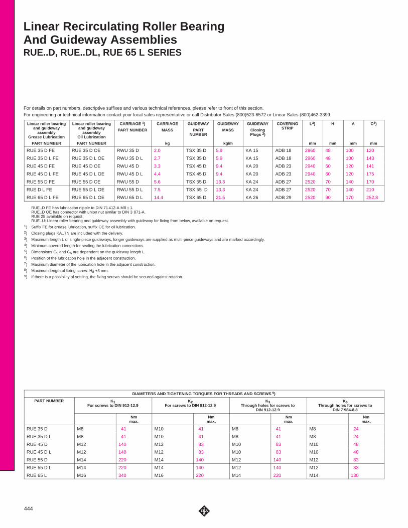
Linear Recirculating Roller BearingAnd Guideway AssembliesRUE..D, RUE..DL, RUE 65 L SERIES
For details on part numbers, descriptive suffixes and various technical references, please refer to front of this section.For engineering or technical information contact your local sales representative or call Distributor Sales (800)523-6572 or Linear Sales (800)462-3399.
444
Linear roller bearingand guideway
assemblyGrease Lubrication
PART NUMBER
Linear roller bearingand guideway
assemblyOil Lubrication
PART NUMBER
CARRIAGE 1)
PART NUMBER
CARRIAGE
MASS
kg
GUIDEWAY
PARTNUMBER
GUIDEWAY
MASS
kg/m
GUIDEWAY
ClosingPlugs 2)
COVERINGSTRIP
L3)
mm
H
mm
A
mm
C4)
mm
RUE 35 D FE RUE 35 D OE RWU 35 D 2.0 TSX 35 D 5.9 KA 15 ADB 18 2960 48 100 120
RUE 35 D L FE RUE 35 D L OE RWU 35 D L 2.7 TSX 35 D 5.9 KA 15 ADB 18 2960 48 100 143
RUE 45 D FE RUE 45 D OE RWU 45 D 3.3 TSX 45 D 9.4 KA 20 ADB 23 2940 60 120 141
RUE 45 D L FE RUE 45 D L OE RWU 45 D L 4.4 TSX 45 D 9.4 KA 20 ADB 23 2940 60 120 175
RUE 55 D FE RUE 55 D OE RWU 55 D 5.6 TSX 55 D 13.3 KA 24 ADB 27 2520 70 140 170
RUE D L FE RUE 55 D L OE RWU 55 D L 7.5 TSX 55 D 13.3 KA 24 ADB 27 2520 70 140 210
RUE 65 D L FE RUE 65 D L OE RWU 65 D L 14.4 TSX 65 D 21.5 KA 26 ADB 29 2520 90 170 252.8
RUE..D FE has lubrication nipple to DIN 71 412-A M8�1.RUE..D OE has connector with union nut similar to DIN 3 871-A.RUE 25 available on request.RUE..U: Linear roller bearing and guideway assembly with guideway for fixing from below, available on request.
1) Suffix FE for grease lubrication, suffix OE for oil lubrication.2) Closing plugs KA..TN are included with the delivery.3) Maximum length L of single-piece guideways, longer guideways are supplied as multi-piece guideways and are marked accordingly.4) Minimum covered length for sealing the lubrication connections.5) Dimensions C5 and C6 are dependent on the guideway length L.6) Position of the lubrication hole in the adjacent construction.7) Maximum diameter of the lubrication hole in the adjacent construction.8) Maximum length of fixing screw: H8 +3 mm.9) If there is a possibility of settling, the fixing screws should be secured against rotation.
DIAMETERS AND TIGHTENING TORQUES FOR THREADS AND SCREWS 9)
PART NUMBER K1For screws to DIN 912-12.9
K2For screws to DIN 912-12.9
K3Through holes for screws to
DIN 912-12.9
K6Through holes for screws to
DIN 7 984-8.8
Nmmax.
Nmmax.
Nmmax.
Nmmax.
RUE 35 D M8 41 M10 41 M8 41 M8 24
RUE 35 D L M8 41 M10 41 M8 41 M8 24
RUE 45 D M12 140 M12 83 M10 83 M10 48
RUE 45 D L M12 140 M12 83 M10 83 M10 48
RUE 55 D M14 220 M14 140 M12 140 M12 83
RUE 55 D L M14 220 M14 140 M12 140 M12 83
RUE 65 L M16 340 M16 220 M14 220 M14 130

Load directions
�� ��
��)
)
*
+
�� ��
��+
�"*
RUE..D(View rotated through 90 �)
RUE..D
��$�( #�'� �)��� �� �
�
������
��)�!� %�$�( �)�
�� �� �
�"��&�!� ����
�'�$���&�"!�"!!��&"$ ��
��$��!�
��
�
��
��
��$��!�
��
��
�
��
AK2 K6 K2
Marking Locating face
Hh
h1
H8H3
Markinga A1
K3H1
H5 H7 H6
Locating face
445
A1
mm
A2
mm
a–0.005–0.035
mm
C1
mm
C2
mm
C3
mm
C4
mm
C55)
min.
mm
C55)
max.
mm
C65)
min.
mm
C65)
max.
mm
C76)
mm
d17)
max.
mm
H1
mm
H3
mm
H5
mm
H6
mm
H7
mm
H88)
mm
h
mm
h1
mm
33 82 34 91.4 62 52 40 20 31 20 31 14.3 6 6.5 6.6 8 20 12 11.1 30 19
33 82 34 114.4 62 52 40 20 31 20 31 25.8 6 6.5 6.6 8 20 12 11.1 30 19
37.5 100 45 107.5 80 60 52.5 20 41 20 41 16.2 6 8.5 8.5 8 26 15 13.5 38 22
37.5 100 45 141.7 80 60 52.5 20 41 20 41 33.3 6 8.5 8.5 8 26 15 13.5 38 22
43.5 116 53 130.8 95 70 60 20 47 20 47 21.2 6 11 10 12 31 18 15.5 45 28
43.5 116 53 170.5 95 70 60 20 47 20 47 41 6 11 10 12 31 18 15.5 45 28
53.5 142 63 207.6 110 82 75 20 61 20 61 49 6 11 10.2 15 39.2 23 23 53.8 30.3
LOAD CARRYING CAPACITY TABLE
PART NUMBER BASIC LOAD RATINGS MOMENT RATINGSPART NUMBER
C
kN
C0
kN
M0x
Nm
M0y
Nm
M0z
Nm
RUE 35 D 59 134 990 2140 1925
RUE 35 D L 70 169 1255 3370 3035
RUE 45 D 92 205 1805 3870 3485
RUE 45 D L 115 275 2410 6770 6095
RUE 55 D 135 305 3130 7035 6335
RUE 55 D L 167 405 4120 12010 10815
RUE 65 D L 270 640 7600 24000 21500

Linear Recirculating Roller BearingAnd Guideway AssembliesRUE..D H, RUE..D HL SERIES
For details on part numbers, descriptive suffixes and various technical references, please refer to front of this section.For engineering or technical information contact your local sales representative or call Distributor Sales (800)523-6572 or Linear Sales (800)462-3399.
446
Linear roller bearingand guideway
assemblyGrease Lubrication
PART NUMBER
Linear roller bearingand guideway
assemblyOil Lubrication
PART NUMBER
CARRIAGE 1)
PART NUMBER
CARRIAGE
MASS
kg
GUIDEWAY
PARTNUMBER
GUIDEWAY
MASS
kg/m
GUIDEWAY
ClosingPlugs 2)
COVERINGSTRIP
L3)
mm
H
mm
A
mm
C4)
mm
RUE 35 D H FE RUE 35 D H OE RWU 35 D H 1.7 TSX 35 D 5.9 KA 15 ADB 18 2 960 55 70 120
RUE 35 D HL FE RUE 35 D HL OE RWU 35 D HL 2.4 TSX 35 D 5.9 KA 15 ADB 18 2 960 55 70 143
RUE 45 D H FE RUE 45 D H OE RWU 45 D H 3.1 TSX 45 D 9.4 KA 20 ADB 23 2 940 70 86 141
RUE 45 D HL FE RUE 45 D HL OE RWU 45 D HL 4.0 TSX 45 D 9.4 KA 20 ADB 23 2 940 70 86 175
RUE 55 D H FE RUE 55 D H OE RWU 55 D H 5.3 TSX 55 D 13.3 KA 24 ADB 24 2 520 80 100 170
RUE 55 D HL FE RUE 55 D HL OE RWU 55 D HL 6.7 TSX 55 D 13.3 KA 24 ADB 24 2 520 80 100 210
RUE 65 D HL FE RUE 65 D HL OE RWU 65 D HL 13.6 TSX 65 D 21.5 KA 26 ADB 26 2 520 100 126 252.8
RUE..D H FE has lubrication nipple to DIN 71 412-A M8�1.RUE..D H OE has connector with union nut similar to DIN 3 871-A.RUE..DU: Linear roller bearing and guideway assembly with guideway for fixing from below, available on request.
1) Suffix FE for grease lubrication, suffix OE for oil lubrication.2) Closing plugs KA..TN are included with the delivery.3) Maximum length L of single-piece guideways, longer guideways are supplied as multi-piece guideways and are marked accordingly.4) Minimum covered length for sealing the lubrication connections.5) Dimensions C5 and C6 are dependent on the guideway length L.6) Position of the lubrication hole in the adjacent construction.7) Maximum diameter of the lubrication hole in the adjacent construction.8) If there is a possibility of settling, the fixing screws should be secured against rotation.
DIAMETERS AND TIGHTENING TORQUES FOR THREADS AND SCREWS 8)
PART NUMBER K1For screws to DIN 912-12.9
K2For screws to DIN 912-12.9
Nmmax.
Nmmax.
RUE 35 D H M8 41 M8 41
RUE 35 D HL M8 41 M8 41
RUE 45 D H M12 140 M10 83
RUE 45 D HL M12 140 M10 83
RUE 55 D H M14 220 M12 140
RUE 55 D HL M14 220 M12 140
RUE 65 D HL M16 340 M14 220
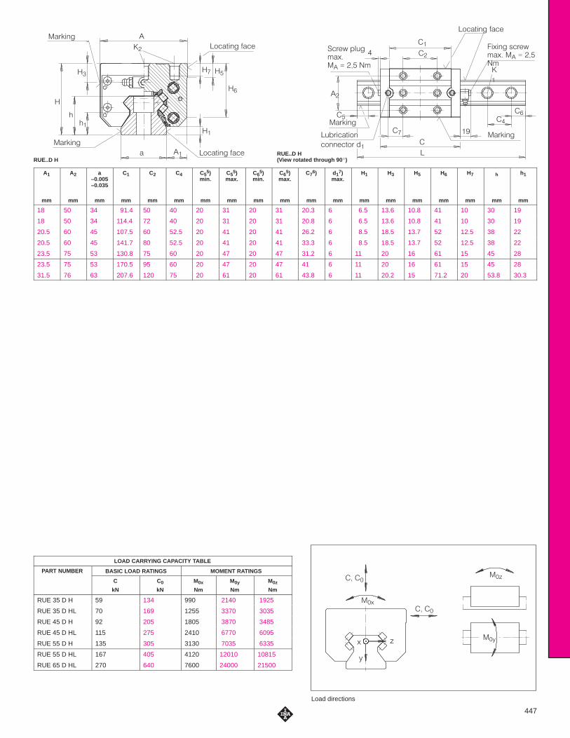
RUE..D H(View rotated through 90 �)RUE..D H
��
�$��(�#� ����
��+�#� '�&�*"�+� �� ���"�
�
���
��
�
�
�
��
�
��
��& �#�
�)�&���(�$#
�$##��($& ��
��& �#�
��&�* %!)�"�+��� �� �"
��
�
��
�
��
���
��& �#�
��& �#�
� ��
��
�$��(�#� ����
�
�
��
�$��(�#� ����
Load directions
�� ��
�� ��
��+
+
,
-
��-
��,
447
A1
mm
A2
mm
a–0.005–0.035
mm
C1
mm
C2
mm
C4
mm
C55)
min.
mm
C55)
max.
mm
C65)
min.
mm
C65)
max.
mm
C76)
mm
d17)
max.
mm
H1
mm
H3
mm
H5
mm
H6
mm
H7
mm
h
mm
h1
mm
18 50 34 91.4 50 40 20 31 20 31 20.3 6 6.5 13.6 10.8 41 10 30 19
18 50 34 114.4 72 40 20 31 20 31 20.8 6 6.5 13.6 10.8 41 10 30 19
20.5 60 45 107.5 60 52.5 20 41 20 41 26.2 6 8.5 18.5 13.7 52 12.5 38 22
20.5 60 45 141.7 80 52.5 20 41 20 41 33.3 6 8.5 18.5 13.7 52 12.5 38 22
23.5 75 53 130.8 75 60 20 47 20 47 31.2 6 11 20 16 61 15 45 28
23.5 75 53 170.5 95 60 20 47 20 47 41 6 11 20 16 61 15 45 28
31.5 76 63 207.6 120 75 20 61 20 61 43.8 6 11 20.2 15 71.2 20 53.8 30.3
LOAD CARRYING CAPACITY TABLE
PART NUMBER BASIC LOAD RATINGS MOMENT RATINGSPART NUMBER
C
kN
C0
kN
M0x
Nm
M0y
Nm
M0z
Nm
RUE 35 D H 59 134 990 2140 1925
RUE 35 D HL 70 169 1255 3370 3035
RUE 45 D H 92 205 1805 3870 3485
RUE 45 D HL 115 275 2410 6770 6095
RUE 55 D H 135 305 3130 7035 6335
RUE 55 D HL 167 405 4120 12010 10815
RUE 65 D HL 270 640 7600 24000 21500
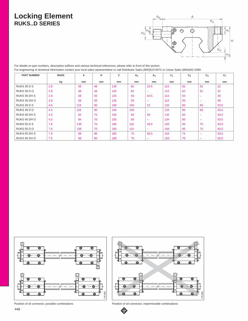
Position of oil connector, impermissible combinationsPosition of oil connector, possible combinations
Locking ElementRUKS..D SERIES
For details on part numbers, descriptive suffixes and various technical references, please refer to front of this section.For engineering or technical information contact your local sales representative or call Distributor Sales (800)523-6572 or Linear Sales (800)462-3399.
���
�
�
�
�
�
�
�������
�������
�������
�������
448
PART NUMBER MASS
kg
A
mm
H
mm
C
mm
A2
mm
A3
mm
C1
mm
C2
mm
C3
mm
C7
mm
RUKS 35 D S 2.8 98 48 135 82 24.5 113 62 52 32
RUKS 35 D O 2.8 98 48 135 82 – 113 62 52 32
RUKS 35 DH S 2.8 68 55 135 50 34.5 113 50 – 38
RUKS 35 DH O 2.8 68 55 135 50 – 113 50 – 38
RUKS 45 D S 4.5 118 60 156 100 22 134 80 60 33.5
RUKS 45 D O 4.5 118 60 156 100 – 134 80 60 33.5
RUKS 45 DH S 4.5 84 70 156 60 39 134 60 – 43.5
RUKS 45 DH O 4.5 84 70 156 60 – 134 60 – 43.5
RUKS 55 D S 7.6 138 70 185 116 18.5 163 95 70 40.5
RUKS 55 D O 7.6 138 70 185 116 – 163 95 70 40.5
RUKS 55 DH S 7.6 98 80 185 75 38.5 163 75 – 50.5
RUKS 55 DH O 7.6 98 80 185 75 – 163 75 – 50.5

Locking ElementRUKS..D SERIES
For details on part numbers, descriptive suffixes and various technical references, please refer to front of this section.For engineering or technical information contact your local sales representative or call Distributor Sales (800)523-6572 or Linear Sales (800)462-3399.
���
��
�
�
��
�
�
RUKS..D S RUKS..D O
�������
�������
��
�
�
�
��
��� ���� ���
��
�
�
�
��
��� ���� ��
449
d1max.
mm
H1
mm
H3
mm
H7
mm
H9
mm
Suitable forguideway
K2
For screws toDIN 912-12.9
K2max.
Nm
K3
Through hole for screws toDIN 912-12.9
K3max.
Nm
PART NUMBER
6 6.5 21 12 13.2 TSX 35 D M10 41 M8 41 RUKS 35 D S
6 6.5 21 12 – TSX 35 D M10 41 M8 41 RUKS 35 D O
6 6.5 42 10 20.2 TSX 35 D M8 41 – – RUKS 35 DH S
6 6.5 42 10 – TSX 35 D M8 41 – – RUKS 35 DH O
6 8,5 27 15 15.6 TSX 45 D M12 83 M10 83 RUKS 45 D S
6 8.5 27 15 – TSX 45 D M12 83 M10 83 RUKS 45 D O
6 8.5 53 10 25.6 TSX 45 D M10 83 – – RUKS 45 DH S
6 8.5 53 10 – TSX 45 D M10 83 – – RUKS 45 DH O
6 11 32 18 18.8 TSX 55 D M14 140 M12 140 RUKS 55 D S
6 11 32 18 – TSX 55 D M14 140 M12 140 RUKS 55 D O
6 11 62 15 28.8 TSX 55 D M12 140 – – RUKS 55 DH S
6 11 62 15 – TSX 55 D M12 140 – – RUKS 55 DH O
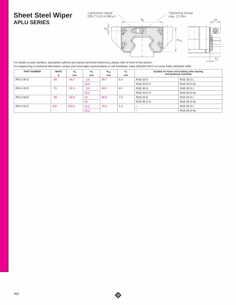
Sheet Steel WiperAPLU SERIES
For details on part numbers, descriptive suffixes and various technical references, please refer to front of this section.For engineering or technical information contact your local sales representative or call Distributor Sales (800)523-6572 or Linear Sales (800)462-3399.
�$�"���#��� �� ����� �&&���'� ���
����#����� #�"!$���%� ��� ��
��
��
���
��
450
PART NUMBER MASS
g
A5
mm
H3
mm
H10
mm
C7
mm
Suitable for linear recirculating roller bearingand guideway assembly
APLU 35 D 60 66.7 6.6 39.7 6.5 RUE 35 D RUE 35 D LAPLU 35 D 60 66.7
13.6
39.7 6.5
RUE 35 D H RUE 35 D HL
APLU 45 D 75 81.5 8.5 49.3 6.5 RUE 45 D RUE 45 D LAPLU 45 D 75 81.5
18.5
49.3 6.5
RUE 45 D H RUE 45 D HL
APLU 55 D 90 94.8 10 56.8 7.5 RUE 55 D RUE 55 D LAPLU 55 D 90 94.8
20
56.8 7.5
RUE 55 D H RUE 55 D HL
APLU 65 D 105 120.3 10.2 76.2 6.3 – RUE 65 D L
20.2 – RUE 65 D HL
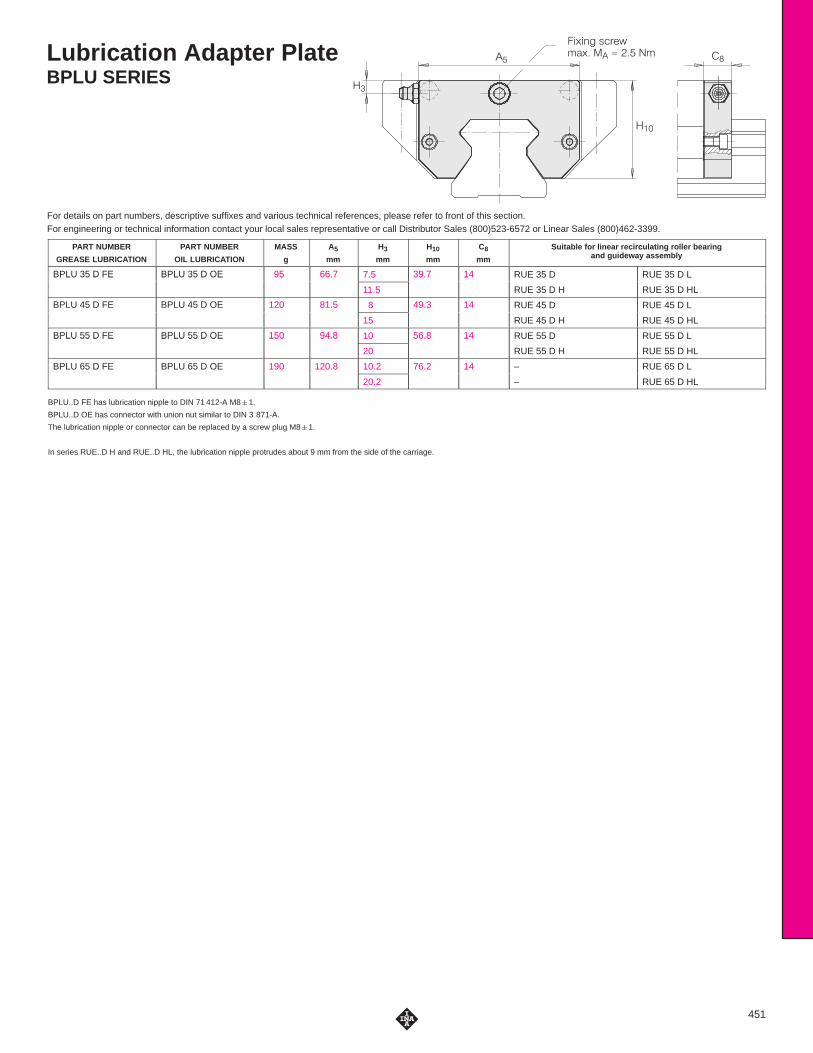
Lubrication Adapter PlateBPLU SERIES
For details on part numbers, descriptive suffixes and various technical references, please refer to front of this section.For engineering or technical information contact your local sales representative or call Distributor Sales (800)523-6572 or Linear Sales (800)462-3399.
������ ��������� � ��� ���
�
��
��
451
PART NUMBER
GREASE LUBRICATION
PART NUMBER
OIL LUBRICATION
MASS
g
A5
mm
H3
mm
H10
mm
C8
mm
Suitable for linear recirculating roller bearingand guideway assembly
BPLU 35 D FE BPLU 35 D OE 95 66.7 7.5 39.7 14 RUE 35 D RUE 35 D LBPLU 35 D FE BPLU 35 D OE 95 66.7
11.5
39.7 14
RUE 35 D H RUE 35 D HL
BPLU 45 D FE BPLU 45 D OE 120 81.5 8 49.3 14 RUE 45 D RUE 45 D LBPLU 45 D FE BPLU 45 D OE 120 81.5
15
49.3 14
RUE 45 D H RUE 45 D HL
BPLU 55 D FE BPLU 55 D OE 150 94.8 10 56.8 14 RUE 55 D RUE 55 D LBPLU 55 D FE BPLU 55 D OE 150 94.8
20
56.8 14
RUE 55 D H RUE 55 D HL
BPLU 65 D FE BPLU 65 D OE 190 120.8 10.2 76.2 14 – RUE 65 D L
20.2 – RUE 65 D HL
BPLU..D FE has lubrication nipple to DIN 71 412-A M8�1.
BPLU..D OE has connector with union nut similar to DIN 3 871-A.
The lubrication nipple or connector can be replaced by a screw plug M8�1.
In series RUE..D H and RUE..D HL, the lubrication nipple protrudes about 9 mm from the side of the carriage.

Minimal Quantity LubricantMetering UnitSMDE SERIES
For details on part numbers, descriptive suffixes and various technical references, please refer to front of this section.For engineering or technical information contact your local sales representative or call Distributor Sales (800)523-6572 or Linear Sales (800)462-3399.
���������� ��������� !��� �������� ������� �� �� �""���#�
��
���
��
�
�
�
������������� ���� ��� ����
126
608
�
������������������� ��
������������� ���� ��� �
126
608
SMDE..D S SMDE..D O
452
PART NUMBER MASS
g
A5
mm
H3
mm
H10
mm
C7with
RUE..DRUE..D H
mm
C7with
RUE..LRUE..D HL
mm
C8
mm
d1max
mm
Suitable for linear recirculating roller bearingand guideway assembly
SMDE 35 D S 170 66.9 6.6 41.1 44 55.5 25 – RUE 35 D RUE 35 D L
SMDE 35 D O 170 66.9 – 41.1 37.2 48.7 25 6 RUE 35 D RUE 35 D L
SMDE 35 D HS 200 66.9 13.6 48.1 50 50.5 25 – RUE 35 D H RUE 35 D HL
SMDE 35 D HO 200 66.9 – 48.1 43.2 43.7 25 6 RUE 35 D H RUE 35 D HL
SMDE 45 D S 200 81.7 8.5 51.2 44.8 61.8 25 – RUE 45 D RUE 45 D L
SMDE 45 D O 200 81.7 – 51.2 38 55 25 6 RUE 45 D RUE 45 D L
SMDE 45 D HS 260 81.7 18.5 61.2 54.8 61.8 25 – RUE 45 D H RUE 45 D HL
SMDE 45 D HO 260 81.7 – 61.2 48 55 25 6 RUE 45 D H RUE 45 D HL
SMDE 55 D S 240 95 10 58.9 51.5 71.5 25 – RUE 55 D RUE 55 D L
SMDE 55 D O 240 95 – 58.9 44.7 64.7 25 6 RUE 55 D RUE 55 D L
SMDE 55 D HS 340 95 20 68.9 61.5 71.5 25 – RUE 55 D H RUE 55 D HL
SMDE 55 D HO 340 95 – 68.9 54.7 64.7 25 6 RUE 55 D H RUE 55 D HL
SMDE 65 D S 500 121 10.2 78.5 – 85 25 – – RUE 65 D L
SMDE 65 D O 500 121 10.2 78.5 – 78.2 25 6 – RUE 65 D L
SMDE 65 D HS 500 121 20.2 88.5 – 80 25 – – RUE 65 D HL
SMDE 65 D HO 500 121 20.2 88.5 – 73.2 25 6 – RUE 65 D HL
In series RUE..D H and RUE..D HL, the lubrication connector protrudes about 9 mm from the side of the carriage.
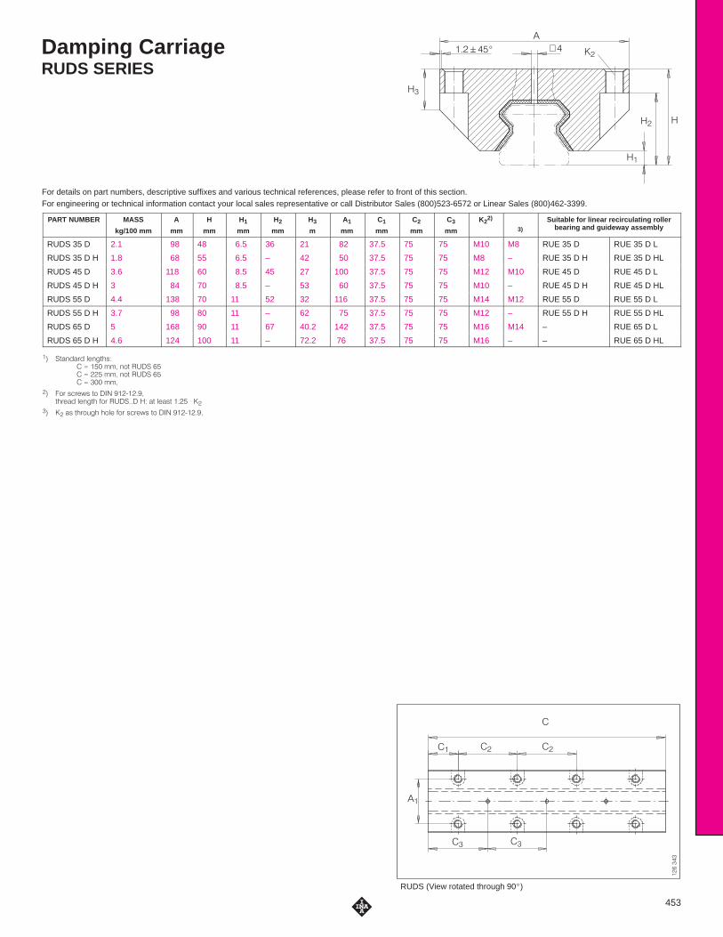
Damping CarriageRUDS SERIES
For details on part numbers, descriptive suffixes and various technical references, please refer to front of this section.For engineering or technical information contact your local sales representative or call Distributor Sales (800)523-6572 or Linear Sales (800)462-3399.
�
�����
��
��
��
�� �
∅
������
RUDS (View rotated through 90�)
�
�� ��
��
�� ��
��
453
PART NUMBER MASS
kg/100 mm
A
mm
H
mm
H1
mm
H2
mm
H3
m
A1
mm
C1
mm
C2
mm
C3
mm
K22)
3)
Suitable for linear recirculating rollerbearing and guideway assembly
RUDS 35 D 2.1 98 48 6.5 36 21 82 37.5 75 75 M10 M8 RUE 35 D RUE 35 D L
RUDS 35 D H 1.8 68 55 6.5 – 42 50 37.5 75 75 M8 – RUE 35 D H RUE 35 D HL
RUDS 45 D 3.6 118 60 8.5 45 27 100 37.5 75 75 M12 M10 RUE 45 D RUE 45 D L
RUDS 45 D H 3 84 70 8.5 – 53 60 37.5 75 75 M10 – RUE 45 D H RUE 45 D HL
RUDS 55 D 4.4 138 70 11 52 32 116 37.5 75 75 M14 M12 RUE 55 D RUE 55 D L
RUDS 55 D H 3.7 98 80 11 – 62 75 37.5 75 75 M12 – RUE 55 D H RUE 55 D HL
RUDS 65 D 5 168 90 11 67 40.2 142 37.5 75 75 M16 M14 – RUE 65 D L
RUDS 65 D H 4.6 124 100 11 – 72.2 76 37.5 75 75 M16 – – RUE 65 D HL
�� �'�#��%� !�#�' & � � �� ""� #$' ���� �� � �� ""� #$' ���� �� � ��� ""�
�� �$% &�%�)& '$ ��� ���+�����' %��� !�#�' �$% ������� � �' !��&' ��� * ��
�� �� �& ' %$(� $!� �$% &�%�)& '$ ��� ���+�����

Linear Recirculating Ball Bearing And GuidewayAssembliesKUSE SERIES
For details on part numbers, descriptive suffixes and various technical references, please refer to front of this section.For engineering or technical information contact your local sales representative or call Distributor Sales (800)523-6572 or Linear Sales (800)462-3399.
L
C6C4C5
a
K7
hH9
Guideway TKSD..U for mounting from below, suffix U (example: KUSE..U)
454
DIMENSION TABLE · Dimensions in mm
UNIT CARRIAGE GUIDEWAY DIMENSIONS MOUNTING DIMENSIONS
PART NUMBER PARTNUMBER
MASS
kg
PARTNUMBER
MASS
kg/m
CLOSINGPLUGS
COVERINGSTRIP
L1) H A C2) A1 A2 a
–0.005–0.03
a3
KUSE 20 KWSE 20 0.43 TKSD 20 2.3 KA 10 TN ADB 13 1,980 30 63 71 21.5 53 20 5
KUSE 25 KWSE 25 0.6 TKSD 25 3.1 KA 11 TN ADB 13 1,980 36 70 81.5 23.5 57 23 6.5
KUSE 30 KWSE 30 1.2 TKSD 30 4.4 KA 15 TN ADB 18 2 ,000 42 90 91.2 31 72 28 9
KUSE 35 KWSE 35 1.5 TKSD 35 6.5 KA 15 TN ADB 18 2 ,960 48 100 106.7 33 82 34 9
KUSE 45 KWSE 45 3.15 TKSD 45 11.3 KA 20 TN ADB 23 2,940 60 120 136.5 37.5 100 45 10
KUSE 55 KWSE 55 4.9 TKSD 55 15.7 KA 24 TN ADB 23 2 ,520 70 140 158 43.5 116 53 12
1) Maximum length L of single piece guideway; longer guideways are supplied as multi-piece guideways and are marked accordingly.
2) Minimum covered length for sealing the lubrication connections.3) Dimensions C5 and C6 are dependent on the guideway length L.4) Position of the lubrication hole in the adjacent construction.5) Maximum diameter of the lubrication hole in the adjacent construction.6) When mounting from above: maximum length of fixing screw for the central fixing holes H8 +3 mm.7) If there is a possibility of settling, the fixing screws should be secured against rotation.
DIAMETERS AND TIGHTENING TORQUES FOR THREADS AND SCREWS 7)
PART NUMBER K1for screws to DIN 912-12.9
K2for screws to DIN 912-12.9
K3Through holes for screws toDIN 912-12.9
K6Through holes for screws toDIN 7 984-8.8
K7for screws to DIN 912-12.9
Nmmax.
Nmmax.
Nmmax.
Nmmax.
Nmmax.
KUSE 20 M5 10 M6 10 M5 10 M5 5.8 M6 17
KUSE 25 M6 17 M8 24 M6 17 M6 10 M6 17
KUSE 30 M8 41 M10 41 M8 41 M8 24 M8 41
KUSE 35 M8 41 M10 41 M8 41 M8 24 M8 41
KUSE 45 M12 140 M12 83 M10 83 M10 48 M12 140
KUSE 55 M14 220 M14 140 M12 140 M12 83 M14 220

�
���"�� �
��
� �
�
�$�"���#�! �! ��#!" ��
�
�
�
��
�!��#� � ����
��
��
�
����
�� � ��� �((���)���
�
������
�
��
�� �
����
��
�
��"�� ��!��#� �����
Load directions
������
��
�
���
��%
��&%
&
'
��'
KUSE, plan view X(rotated through 90 �)
KUSE
455
C1 C2 C3 C4 C53) C6
3) C74) d1
5) H1 H2 H4 H5 H86) H9 h h1
min. max. min. max. max.
52 40 35 60 20 53 20 53 9.8 3 4.6 5 10 10.4 7.2 10 18 10.3
60.5 45 40 60 20 53 20 53 12.8 3 5.2 5 10 9.5 9.5 12 21.7 12.7
67.2 52 44 80 20 71 20 71 12.6 4.5 5.5 6 12 11.9 10 15 25 14
77.7 62 52 80 20 71 20 71 11.7 4.5 6.6 6.5 13 13 12 15 29.7 18.7
102.5 80 60 105 20 94 20 94 15.8 6 8.6 9 15 15.5 15 20 37.2 21.2
117.7 95 70 120 20 107 20 107 19.2 6 10.8 12 18 18.6 17 22 44 27
LOAD CARRYING CAPACITY TABLE
PART NUMBER BASIC LOAD RATINGS MOMENT RATINGS
LOAD DIRECTION I: COMPRESSIVE LOAD
LOAD DIRECTION II: TENSILE LOAD
LOAD DIRECTION III: LATERAL LOAD
C
kN
C0
kN
C
kN
C0
kN
C
kN
C0
kN
M0x
Nm
M0y
Nm
M0z
Nm
KUSE 20 22 52 17.5 33.5 16.3 36 358 333 303
KUSE 25 28 67 22.9 43 21.3 46 535 486 442
KUSE 30 40 80 33 60 30.5 64 896 762 694
KUSE 35 55 102 45 79 42 85 1 ,454 1,173 1,069
KUSE 45 80 174 65 117 59 126 2 ,794 2,237 2,037
KUSE 55 102 230 81 147 75 157 4 ,114 3,141 2 ,861

Linear Recirculating Ball Bearing And Guideway AssembliesKUSE..L SERIES
For details on part numbers, descriptive suffixes and various technical references, please refer to front of this section.For engineering or technical information contact your local sales representative or call Distributor Sales (800)523-6572 or Linear Sales (800)462-3399.
L
C6C4C5
a
K7
hH9
Guideway TKSD..U for mounting from below, suffix U (example: KUSE..U)
456
DIMENSION TABLE · Dimensions in mm
UNIT Carriage GUIDEWAY DIMENSIONS MOUNTING DIMENSIONS
PART NUMBER PART NUMBER MASS
kg
PART NUMBER MASS
kg/m
CLOSINGPLUGS
COVERINGSTRIP
L1) H A C2) A1 A2 a
–0.005–0.03
a3
KUSE 20 L KWSE 20 L 0.6 TKSD 20 2.3 KA 10 TN ADB 13 1 ,980 30 63 90.8 21.5 53 20 5
KUSE 25 L KWSE 25 L 0.82 TKSD 25 3.1 KA 11 TN ADB 13 1,980 36 70 104 23.5 57 23 6.5
KUSE 30 L KWSE 30 L 1.6 TKSD 30 4.4 KA 15 TN ADB 18 2,000 42 90 118.7 31 72 28 9
KUSE 35 L KWSE 35 L 2.1 TKSD 35 6.5 KA 15 TN ADB 18 2,960 48 100 138.4 33 82 34 9
KUSE 45 L KWSE 45 L 4.2 TKSD 45 11.3 KA 20 TN ADB 23 2 ,940 60 120 172.2 37.5 100 45 10
KUSE 55 L KWSE 55 L 6.6 TKSD 55 15.7 KA 24 TN ADB 23 2 ,520 70 140 198 43.5 116 53 12
1) Maximum length L of single piece guideway; longer guideways are supplied as multi-piece guideways and are marked accordingly.
2) Minimum covered length for sealing the lubrication connections.3) Dimensions C5 and C6 are dependent on the guideway length L.4) Position of the lubrication hole in the adjacent construction.5) Maximum diameter of the lubrication hole in the adjacent construction.6) When mounting from above: maximum length of fixing screw for the central fixing holes H8 +3 mm.7) If there is a possibility of settling, the fixing screws should be secured against rotation.
DIAMETERS AND TIGHTENING TORQUES FOR THREADS AND SCREWS 7)
PART NUMBER K1for screws to DIN 912-12.9
K2for screws to DIN 912–12.9
K3Through holes for screws toDIN 912-12.9
K6Through holes for screws toDIN 7 984-8.8
K7for screws to DIN 912-12.9
Nmmax.
Nmmax.
Nmmax.
Nmmax.
Nmmax.
KUSE 20 L M5 10 M6 10 M5 10 M5 5.8 M6 17
KUSE 25 L M6 17 M8 24 M6 17 M6 10 M6 17
KUSE 30 L M8 41 M10 41 M8 41 M8 24 M8 41
KUSE 35 L M8 41 M10 41 M8 41 M8 24 M8 41
KUSE 45 L M12 140 M12 83 M10 83 M10 48 M12 140
KUSE 55 L M14 220 M14 140 M12 140 M12 83 M14 220

�
���"�� �
��
� ��
�$�"���#�! �! ��#!" ��
�
�
�
��
�!��#� � ����
�� ��
�
����
�� � ��� �((���)���
�
������
�
��
�� �
����
��
�
��"�� ��!��#� �����
Load directions
������
��
�
���
��%
��&%
&
'
��'
KUSE..L, plan view X(rotated through 90 �)
KUSE..L
457
C1 C2 C3 C4 C53) C6
3} C74) d1
5) H1 H2 H4 H5 H86) H9 h h1
min. max. min max. max.
71.8 40 35 60 20 53 20 53 19.7 3 4.6 5 10 10.4 7.2 10 18 10.3
83 45 40 60 20 53 20 53 24 3 5.2 5 10 9.5 9.5 12 21.7 12.7
94.7 52 44 80 20 71 20 71 26.3 4.5 5.5 6 12 11.9 10 15 25 14
109.4 62 52 80 20 71 20 71 27.5 4.5 6.6 6.5 13 13 12 15 29.7 18.7
138.2 80 60 105 20 94 20 94 33.6 6 8.6 9 15 15.5 15 20 37.2 21.2
157.7
�
95 70 120 20 107 20 107 39.2 6 10.8 12 18 18.6 17 22 44 27
LOAD CARRYING CAPACITY TABLE
PART NUMBER BASIC LOAD RATINGS MOMENT RATINGS
LOAD DIRECTION I: COMPRESSIVE LOAD
LOAD DIRECTION II: TENSILE LOAD
LOAD DIRECTION III: LATERAL LOAD
C
kN
C0
kN
C
kN
C0
kN
C
kN
C0
kN
M0x
Nm
M0y
Nm
M0z
Nm
KUSE 20 L 28 72 22.2 46.5 18.9 50 494 619 564.6
KUSE 25 L 35.3 93.7 28.9 59.8 24.7 64 736 903 823
KUSE 30 L 51 113 42.4 84.3 36.5 90 1,265 1,478 1,346
KUSE 35 L 70 145 57.3 112.4 49.5 120 2 ,054 2 ,275 2,072
KUSE 45 L 98 236 79.3 159 69 170 3,792 4,011 3,654
KUSE 55 L 125.4 312 100.6 199.4 87 214 5,584 5 ,633 5,132

Linear Recirculating Ball Bearing And Guideway AssembliesKUSE..H SERIES
For details on part numbers, descriptive suffixes and various technical references, please refer to front of this section.For engineering or technical information contact your local sales representative or call Distributor Sales (800)523-6572 or Linear Sales (800)462-3399.
L
C6C4C5
a
K7
hH9
Guideway TKSD..U for mounting from below, suffix U (example: KUSE..U)
458
DIMENSION TABLE · Dimensions in mm
UNIT CARRIAGE GUIDEWAY DIMENSIONS MOUNTING DIMENSIONS
PART NUMBER PART NUMBER MASS
kg
PART NUMBER Mass
kg/m
CLOSINGPLUGS
COVERINGSTRIP
L1) H A C2) A1 A2 a
–0.005–0.03
a3
KUSE 20 H KWSE 20 H 0.32 TKSD 20 2.3 KA 10 TN ADB 13 1,980 30 44 71 12 32 20 6
KUSE 25 H KWSE 25 H 0.5 TKSD 25 3.1 KA 11 TN ADB 13 1,980 40 48 81.5 12.5 35 23 6.5
KUSE 30 H KWSE 30 H 0.9 TKSD 30 4.4 KA 15 TN ADB 18 2,000 45 60 91.2 16 40 28 10
KUSE 35 H KWSE 35 H 1.3 TKSD 35 6.5 KA 15 TN ADB 18 2,960 55 70 106.7 18 50 34 10
KUSE 45 H KWSE 45 H 2.75 TKSD 45 11.3 KA 20 TN ADB 23 2,940 70 86 136.5 20.5 60 45 13
KUSE 55 H KWSE 55 H 4.5 TKSD 55 15.7 KA 24 TN ADB 23 2,520 80 100 158 23.5 75 53 12.5
1) Maximum length L of single piece guideway; longer guideways are supplied as multi-piece guideways and are marked accordingly.
2) Minimum covered length for sealing the lubrication connections.3) Dimensions C5 and C6 are dependent on the guideway length L.4) Position of the lubrication hole in the adjacent construction.5) Maximum diameter of the lubrication hole in the adjacent construction.6) If there is a possibility of settling, the fixing screws should be secured against rotation.
DIAMETERS AND TIGHTENING TORQUES FOR THREADS AND SCREWS 6)
PART NUMBER K1for screws to DIN 912-12.9
K2for screws to DIN 912-12.9
K7for screws to DIN 912-12.9
Nmmax.
Nmmax.
Nmmax.
KUSE 20 H M5 10 M5 10 M6 17
KUSE 25 H M6 17 M6 17 M6 17
KUSE 30 H M8 41 M8 41 M8 41
KUSE 35 H M8 41 M8 41 M8 41
KUSE 45 H M12 140 M10 83 M12 140
KUSE 55 H M14 220 M12 140 M14 220
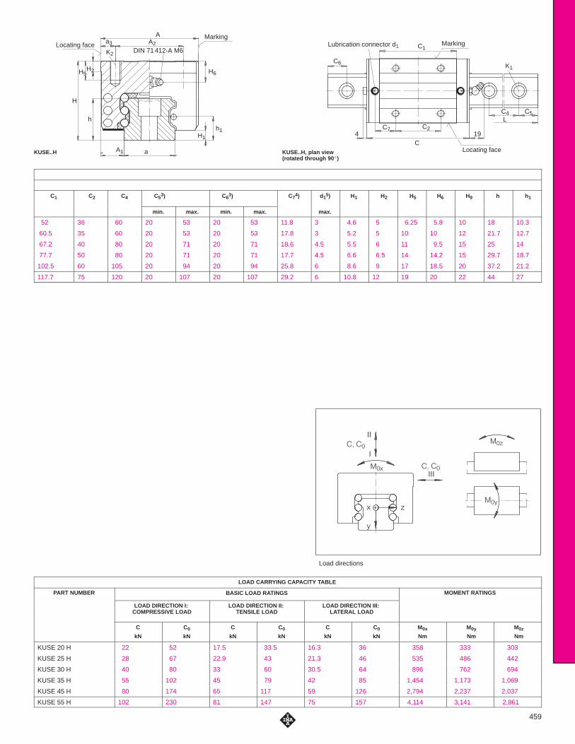
DIN 71 412-A M6Locating face
Marking
aA1
H
h
H5 H6
H1
h1
Aa3 A2
H2
K2C1
C6
194C
C2
Marking
Locating face
Lubrication connector d1
C7
C4L
C5
K1
Load directions
���
��
���
�
��
���
�� ��
�� ��
�
�
KUSE..H, plan view(rotated through 90 �)
KUSE..H
459
C1 C2 C4 C53) C6
3) C74) d1
5) H1 H2 H5 H6 H9 h h1
min. max. min. max. max.
52 36 60 20 53 20 53 11.8 3 4.6 5 6.25 5.8 10 18 10.3
60.5 35 60 20 53 20 53 17.8 3 5.2 5 10 10 12 21.7 12.7
67.2 40 80 20 71 20 71 18.6 4.5 5.5 6 11 9.5 15 25 14
77.7 50 80 20 71 20 71 17.7 4.5 6.6 6.5 14 14.2 15 29.7 18.7
102.5 60 105 20 94 20 94 25.8 6 8.6 9 17 18.5 20 37.2 21.2
117.7 75 120 20 107 20 107 29.2 6 10.8 12 19 20 22 44 27
LOAD CARRYING CAPACITY TABLE
PART NUMBER BASIC LOAD RATINGS MOMENT RATINGS
LOAD DIRECTION I: COMPRESSIVE LOAD
LOAD DIRECTION II: TENSILE LOAD
LOAD DIRECTION III: LATERAL LOAD
C
kN
C0
kN
C
kN
C0
kN
C
kN
C0
kN
M0x
Nm
M0y
Nm
M0z
Nm
KUSE 20 H 22 52 17.5 33.5 16.3 36 358 333 303
KUSE 25 H 28 67 22.9 43 21.3 46 535 486 442
KUSE 30 H 40 80 33 60 30.5 64 896 762 694
KUSE 35 H 55 102 45 79 42 85 1,454 1,173 1,069
KUSE 45 H 80 174 65 117 59 126 2,794 2,237 2,037
KUSE 55 H 102 230 81 147 75 157 4,114 3,141 2,861

Linear Recirculating Ball Bearing And Guideway AssembliesKUSE..HL SERIES
For details on part numbers, descriptive suffixes and various technical references, please refer to front of this section.For engineering or technical information contact your local sales representative or call Distributor Sales (800)523-6572 or Linear Sales (800)462-3399.
L
C6C4C5
a
K7
hH9
Guideway TKSD..U for mounting from below, suffix U (example: KUSE..U)
460
DIMENSION TABLE · Dimensions in mm
UNIT CARRIAGE GUIDEWAY DIMENSIONS MOUNTING DIMENSIONS
PART NUMBER PART NUMBER MASS
kg
PARTNUMBER
MASS
kg/m
CLOSINGPLUGS
COVERINGSTRIP
L1) H A C2) A1 A2 a
–0.05–0.03
a3
KUSE 20 HL KWSE 20 HL 0.44 TKSD 20 2.3 KA 10 TN ADB 13 1,980 30 44 90.8 12 32 20 6
KUSE 25 HL KWSE 25 HL 0.7 TKSD 25 3.15 KA 11 TN ADB 13 1,980 40 48 104 12.5 35 23 6.5
KUSE 30 HL KWSE 30 HL 1.2 TKSD 30 4.4 KA 15 TN ADB 18 2,000 45 60 118.7 16 40 28 10
KUSE 35 HL KWSE 35 HL 1.8 TKSD 35 6.5 KA 15 TN ADB 18 2,960 55 70 138.4 18 50 34 10
KUSE 45 HL KWSE 45 HL 3.7 TKSD 45 11.3 KA 20 TN ADB 23 2,940 70 86 172.2 20.5 60 45 13
KUSE 55 HL KWSE 55 HL 5.9 TKSD 55 15.7 KA 24 TN ADB 23 2,520 80 100 198 23.5 75 53 12.5
1) Maximum length L of single piece guideway; longer guideways are supplied as multi-piece guideways and are marked accordingly.
2) Minimum covered length for sealing the lubrication connections.3) Dimensions C5 and C6 are dependent on the guideway length L.4) Position of the lubrication hole in the adjacent construction.5) Maximum diameter of the lubrication hole in the adjacent construction.6) If there is a possibility of settling, the fixing screws should be secured against rotation.
DIAMETERS AND TIGHTENING TORQUES FOR THREADS AND SCREWS 6)
PART NUMBER K1for screws to DIN 912-12.9
K2for screws to DIN 912-12.9
K7for screws to DIN 912-12.9
Nmmax.
Nmmax.
Nmmax.
KUSE 20 HL M5 10 M5 10 M6 17
KUSE 25 HL M6 17 M6 17 M6 17
KUSE 30 HL M8 41 M8 41 M8 41
KUSE 35 HL M8 41 M8 41 M8 41
KUSE 45 HL M12 140 M10 83 M12 140
KUSE 55 HL M14 220 M12 140 M14 220
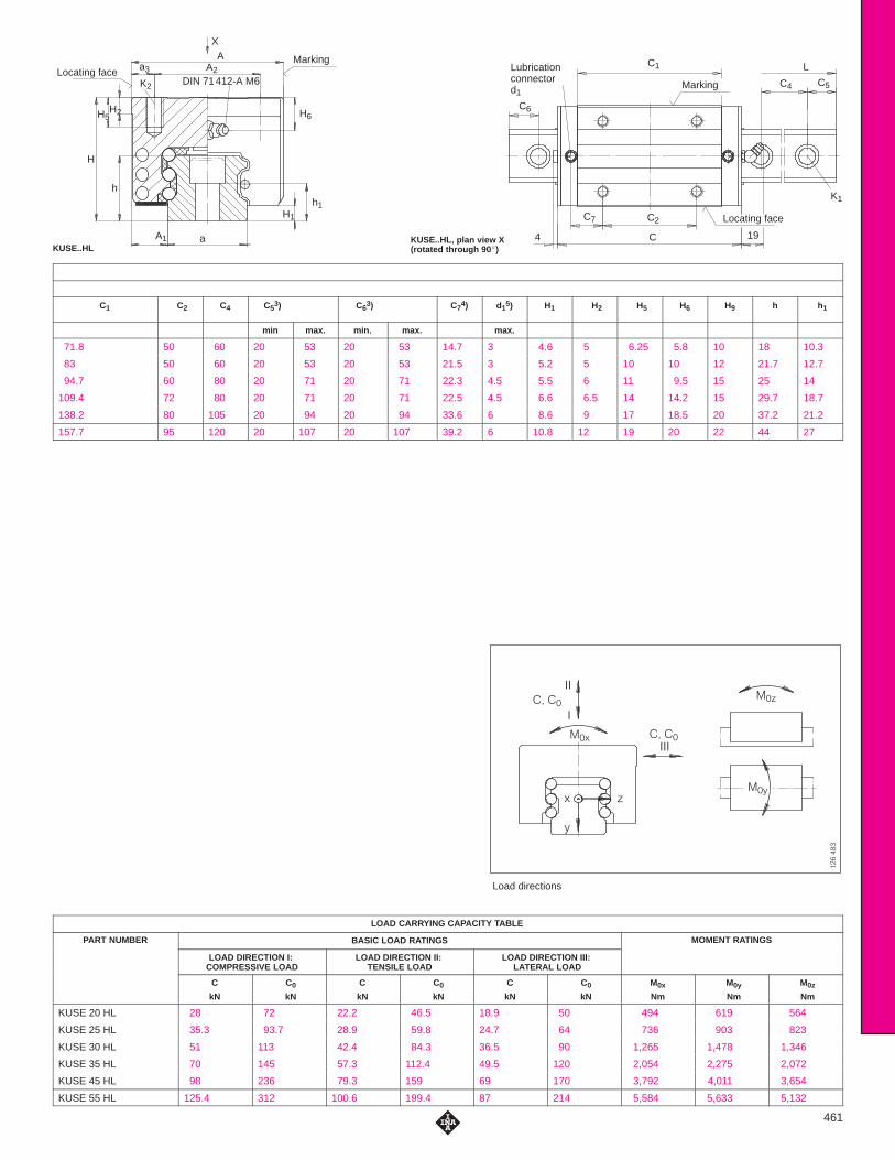
X
DIN 71 412-A M6Locating face
Marking
aA1
H
h
H5 H6
H1
h1
Aa3 A2
H2
K2
C1
4 19C
C2C7
L
C4 C5
C6
K1
Lubricationconnector d1
Marking
Locating face
Load directions
������
��
���
���
�
��
���
� �
� �
�
�
KUSE..HL, plan view X(rotated through 90 �)KUSE..HL
461
C1 C2 C4 C53) C6
3) C74) d1
5) H1 H2 H5 H6 H9 h h1
min max. min. max. max.
71.8 50 60 20 53 20 53 14.7 3 4.6 5 6.25 5.8 10 18 10.3
83 50 60 20 53 20 53 21.5 3 5.2 5 10 10 12 21.7 12.7
94.7 60 80 20 71 20 71 22.3 4.5 5.5 6 11 9.5 15 25 14
109.4 72 80 20 71 20 71 22.5 4.5 6.6 6.5 14 14.2 15 29.7 18.7
138.2 80 105 20 94 20 94 33.6 6 8.6 9 17 18.5 20 37.2 21.2
157.7 95 120 20 107 20 107 39.2 6 10.8 12 19 20 22 44 27
LOAD CARRYING CAPACITY TABLE
PART NUMBER BASIC LOAD RATINGS MOMENT RATINGS
LOAD DIRECTION I: COMPRESSIVE LOAD
LOAD DIRECTION II: TENSILE LOAD
LOAD DIRECTION III: LATERAL LOAD
C
kN
C0
kN
C
kN
C0
kN
C
kN
C0
kN
M0x
Nm
M0y
Nm
M0z
Nm
KUSE 20 HL 28 72 22.2 46.5 18.9 50 494 619 564
KUSE 25 HL 35.3 93.7 28.9 59.8 24.7 64 736 903 823
KUSE 30 HL 51 113 42.4 84.3 36.5 90 1,265 1,478 1,346
KUSE 35 HL 70 145 57.3 112.4 49.5 120 2,054 2,275 2,072
KUSE 45 HL 98 236 79.3 159 69 170 3,792 4,011 3,654
KUSE 55 HL 125.4 312 100.6 199.4 87 214 5,584 5,633 5,132

Sheet Steel WiperAPLSE SERIES
For details on part numbers, descriptive suffixes and various technical references, please refer to front of this section.For engineering or technical information contact your local sales representative or call Distributor Sales (800)523-6572 or Linear Sales (800)462-3399.
�
��
�
�&�$���%�! �""����� ��(���)� ���� ����%� � �
%!$#&���'� �� ��
��
���
�� �
462
DIMENSION TABLE · Dimensions in mm
PART NUMBER MASS DIMENSIONS SUITABLE FOR LINEAR RECIRCULATING BALL BEARING
gA4 H9 C8 H6
LINEAR RECIRCULATING BALL BEARING AND GUIDEWAY ASSEMBLY
APLSE 20 26 42.8 24.9 0.8 5.8 KUSE 20 KUSE 20 LAPLSE 20 26 42.8 24.9 0.8
5.8 KUSE 20 H KUSE 20 HL
APLSE 25 27 46 30.1 0.8 6 KUSE 25 KUSE 25 LAPLSE 25 27 46 30.1 0.8
10 KUSE 25 H KUSE 25 HL
APLSE 30 31 58 35.8 0.8 6.5 KUSE 30 KUSE 30 LAPLSE 30 31 58 35.8 0.8
9.5 KUSE 30 H KUSE 30 HL
APLSe 35 34 68 40.7 0.8 7.2 KUSE 35 KUSE 35 LAPLSe 35 34 68 40.7 0.8
14.2 KUSE 35 H KUSE 35 HL
APLSE 45 40 84 50.7 0.8 8.5 KUSE 45 KUSE 45 LAPLSE 45 40 84 50.7 0.8
8.5 KUSE 45 H KUSE 45 HL
APLSE 55 46 96.4 58.5 0.8 10 KUSE 55 KUSE 55 L
20 KUSE 55 H KUSE 55 HL
When fitting the wiper, it must be ensured that the gap between the guideway and the sheet steel wiper is of the correct size (see figure above).

Collector WiperAB KOL KWSE SERIES
For details on part numbers, descriptive suffixes and various technical references, please refer to front of this section.For engineering or technical information contact your local sales representative or call Distributor Sales (800)523-6572 or Linear Sales (800)462-3399.
�$�"���#��� �� ����� �&���'� ���
����#����� #�"!$���%� ��� ��
��
��
����
� ��
463
DIMENSION TABLE · Dimensions in mm
PART NUMBER MASS DIMENSIONS SUITABLE FOR LINEAR RECIRCULATING BALL BEARING
gA4 H9 C9 H6
LINEAR RECIRCULATING BALL BEARING AND GUIDEWAY ASSEMBLY
AB KOL KWSE 20 46 42.8 24.9 9 5.8 KUSE 20 KUSE 20 L
5.8 KUSE 20 H KUSE 20 HL
AB KOL KWSE 25 51 46 30.1 9 6 KUSE 25 KUSE 25 L
10 KUSE 25 H KUSE 25 HL
AB KOL KWSE 30 69 58 35.8 9 6.5 KUSE 30 KUSE 30 L
9.5 KUSE 30 H KUSE 30 HL
AB KOL KWSE 35 82 68 40.7 9 7.2 KUSE 35 KUSE 35 L
14.2 KUSE 35 H KUSE 35 HL
AB KOL KWSE 45 109 84 50.7 11 8.5 KUSE 45 KUSE 45 L
18.5 KUSE 45 H KUSE 45 HL
AB KOL KWSE 55 136 96.4 58.5 11 10 KUSE 55 KUSE 55 L
20 KUSE 55 H KUSE 55 HL
If the collector wiper AB KOL KWSE is used, the covering strip ADBSE or closing plugs KA..M must be used.

Lubrication Adapter PlateBPLSE SERIES
For details on part numbers, descriptive suffixes and various technical references, please refer to front of this section.For engineering or technical information contact your local sales representative or call Distributor Sales (800)523-6572 or Linear Sales (800)462-3399.
��
��
��
�#�!���"��� ������ �� �%���&� ���
����"�����"�! #���$� ��� ��
��
���
464
DIMENSION TABLE · Dimensions in mm
PART NUMBER Mass DIMENSIONS SUITABLE FOR LINEAR RECIRCULATING BALL BEARING
gA4 H9 H6
LINEAR RECIRCULATING BALL BEARING AND GUIDEWAY ASSEMBLY
BPLSE 20 29 42.8 24.9 5.8 KUSE 20 KUSE 20 LBPLSE 20 29 42.8 24.9
5.8 KUSE 20 H KUSE 20 HL
BPLSE 25 35 46 30.1 6 KUSE 25 KUSE 25 LBPLSE 25 35 46 30.1
10 KUSE 25 H KUSE 25 HL
BPLSE 30 52 58 35.8 6.5 KUSE 30 KUSE 30 LBPLSE 30 52 58 35.8
9.5 KUSE 30 H KUSE 30 HL
BPLSE 35 67 68 40.7 7.2 KUSE 35 KUSE 35 LBPLSE 35 67 68 40.7
14.2 KUSE 35 H KUSE 35 HL
BPLSE 45 98 84 50.7 8.5 KUSE 45 KUSE 45 LBPLSE 45 98 84 50.7
18.5 KUSE 45 H KUSE 45 HL
BPLSE 55 128 96.4 58.5 10 KUSE 55 KUSE 55 LBPLSE 55 128 96.4 58.5
20 KUSE 55 H KUSE 55 HL
The lubrication nipple to DIN 71412-A M8�1 can be replaced by a screw plug M8�1.
Note:
In series KUSE..H and KUSE..HL. the lubrication nipple protrudes about 9 mm from the side of the carriage.

BellowsFBALG KWSE SERIES
For details on part numbers, descriptive suffixes and various technical references, please refer to front of this section.For engineering or technical information contact your local sales representative or call Distributor Sales (800)523-6572 or Linear Sales (800)462-3399.
��� � ���
��
�
�����
���
��� ������
�
����
�
�
�
�
465
Dimension table · Dimensions in mm
PART NUMBER DIMENSIONS SUITABLE FOR LINEAR RECIRCULATING BALL BEARING
A a11) a2 H H1 h1 h2 h3 ApF
2) lp min3)
RECIRCULATING BALL BEARING AND GUIDEWAY ASSEMBLY
FBALG KWSE�20 63 42.8 21 30 4.8 24.9 11 24.2 14.5 2.5 KUSE 20 KUSE 20 L
44 30 KUSE 20 H KUSE 20 HL
FBALG KWSE�25 70 46 24 36 5.4 30.1 11 30 14.5 2.5 KUSE 25 KUSE 25 L
48 40 KUSE 25 H KUSE 25 HL
FBALG KWSE�30 90 58 29 42 5.7 35.8 14 35.5 18 2.5 KUSE 30 KUSE 30 L
60 45 KUSE 30 H KUSE 30 HL
FBALG KWSE�35 100 68 35 48 6.8 40.7 16 40.8 22.5 2.5 KUSE 35 KUSE 35 L
70 55 KUSE 35 H KUSE 35 HL
FBALG KWSE�45 120 84 46 60 8.8 50.7 19 51.5 27 2.5 KUSE 45 KUSE 45 L
86 70 KUSE 45 H KUSE 45 HL
FBALG KWSE�55 140 96.4 56 70 11 58.5 21 60 31.5 2.5 KUSE 55 KUSE 55 L
100 80 KUSE 55 H KUSE 55 HL
1) Maximum width of bellows in end gauge.2) Expansion per pleat.3) Compression per pleat.
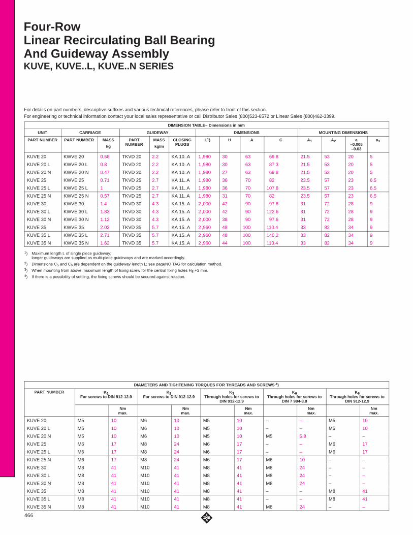
Four-RowLinear Recirculating Ball BearingAnd Guideway AssemblyKUVE, KUVE..L, KUVE..N SERIES
For details on part numbers, descriptive suffixes and various technical references, please refer to front of this section.For engineering or technical information contact your local sales representative or call Distributor Sales (800)523-6572 or Linear Sales (800)462-3399.
466
DIMENSION TABLE– Dimensions in mm
UNIT CARRIAGE GUIDEWAY DIMENSIONS MOUNTING DIMENSIONS
PART NUMBER PART NUMBER MASS
kg
PARTNUMBER
MASS
kg/m
CLOSINGPLUGS
L1) H A C A1 A2 a–0.005–0.03
a3
KUVE 20 KWVE 20 0.58 TKVD 20 2.2 KA 10..A 1 ,980 30 63 69.8 21.5 53 20 5
KUVE 20 L KWVE 20 L 0.8 TKVD 20 2.2 KA 10..A 1 ,980 30 63 87.3 21.5 53 20 5
KUVE 20 N KWVE 20 N 0.47 TKVD 20 2.2 KA 10..A 1 ,980 27 63 69.8 21.5 53 20 5
KUVE 25 KWVE 25 0.71 TKVD 25 2.7 KA 11..A 1 ,980 36 70 82 23.5 57 23 6.5
KUVE 25 L KWVE 25 L 1 TKVD 25 2.7 KA 11..A 1 ,980 36 70 107.8 23.5 57 23 6.5
KUVE 25 N KWVE 25 N 0.57 TKVD 25 2.7 KA 11..A 1 ,980 31 70 82 23.5 57 23 6.5
KUVE 30 KWVE 30 1.4 TKVD 30 4.3 KA 15..A 2 ,000 42 90 97.6 31 72 28 9
KUVE 30 L KWVE 30 L 1.83 TKVD 30 4.3 KA 15..A 2 ,000 42 90 122.6 31 72 28 9
KUVE 30 N KWVE 30 N 1.12 TKVD 30 4.3 KA 15..A 2 ,000 38 90 97.6 31 72 28 9
KUVE 35 KWVE 35 2.02 TKVD 35 5.7 KA 15..A 2 ,960 48 100 110.4 33 82 34 9
KUVE 35 L KWVE 35 L 2.71 TKVD 35 5.7 KA 15..A 2 ,960 48 100 140.2 33 82 34 9
KUVE 35 N KWVE 35 N 1.62 TKVD 35 5.7 KA 15..A 2 ,960 44 100 110.4 33 82 34 9
1) Maximum length L of single piece guideway; longer guideways are supplied as multi-piece guideways and are marked accordingly.
2) Dimensions C5 and C6 are dependent on the guideway length L; see pageNO TAG for calculation method.3) When mounting from above: maximum length of fixing screw for the central fixing holes H8 +3 mm.4) If there is a possibility of settling, the fixing screws should be secured against rotation.
DIAMETERS AND TIGHTENING TORQUES FOR THREADS AND SCREWS 4)
PART NUMBER K1For screws to DIN 912-12.9
K2For screws to DIN 912-12.9
K3Through holes for screws to
DIN 912-12.9
K6Through holes for screws to
DIN 7 984-8.8
K6Through holes for screws to
DIN 912-12.9
Nmmax.
Nmmax.
Nmmax.
Nmmax.
Nmmax.
KUVE 20 M5 10 M6 10 M5 10 – – M5 10
KUVE 20 L M5 10 M6 10 M5 10 – – M5 10
KUVE 20 N M5 10 M6 10 M5 10 M5 5.8 – –
KUVE 25 M6 17 M8 24 M6 17 – – M6 17
KUVE 25 L M6 17 M8 24 M6 17 – – M6 17
KUVE 25 N M6 17 M8 24 M6 17 M6 10 – –
KUVE 30 M8 41 M10 41 M8 41 M8 24 – –
KUVE 30 L M8 41 M10 41 M8 41 M8 24 – –
KUVE 30 N M8 41 M10 41 M8 41 M8 24 – –
KUVE 35 M8 41 M10 41 M8 41 – – M8 41
KUVE 35 L M8 41 M10 41 M8 41 – – M8 41
KUVE 35 N M8 41 M10 41 M8 41 M8 24 – –

Load directions
��"
��$
��#"
#
$
KUVEKUVE, plan view X(rotated through 90 °)
����!��� ���� �� ����
��
�
�� �
�� ��
��� �%%���&� ��
������
�
���
�� �
����
� ��
�
�
�� ����
��
� �
�
��
����!��� ���� �
��
��
�
�
467
DIMENSION TABLE– Dimensions in mm
MOUNTING DIMENSIONS
C1 C2 C3 C4 C52) C5
2)
max.
C62)
min.
C62)
max.
H1 H2 H4 H5 H6 H83) h h1
50.4 40 35 60 20 53 20 53 4.6 5 10 11.6 8 7.5 17 9.1
67.9 40 35 60 20 53 20 53 4.6 5 10 10.8 8 7.5 17 9.1
50.4 40 35 60 20 53 20 53 4.6 5 8 8.6 5 6 17 9.1
60.7 45 40 60 20 53 20 53 5.2 5 10 10.9 11 10 18,7 8.7
86.5 45 40 60 20 53 20 53 5.2 5 10 10.9 11 10 18,7 8.7
60.7 45 40 60 20 53 20 53 5.2 5 10 4.3 6 8 18,7 8.7
72 52 44 80 20 71 20 71 6 6 12 13.8 11.25 12 23,5 11.5
97 52 44 80 20 71 20 71 6 6 12 13.8 11.25 12 23,5 11.5
72 52 44 80 20 71 20 71 6 6 12 9.8 7.25 9 23,5 11.5
80 62 52 80 20 71 20 71 6,8 6.5 13 14.3 12.3 12 27 15
109.8 62 52 80 20 71 20 71 6.8 6.5 13 14.3 12.3 12 27 15
80 62 52 80 20 71 20 71 6.8 6.5 13 10.7 8.3 11.7 27 15
LOAD CARRYING CAPACITY TABLE
PART NUMBER BASIC LOAD RATINGS MOMENT RATINGSPART NUMBER
C
kN
C0
kN
M0x
Nm
M0y
Nm
M0z
Nm
KUVE 20 13.1 26.9 332 240 240
KUVE 20 L 16.2 36.5 452 430 430
KUVE 20 N 13.1 26.9 332 240 240
KUVE 25 17.9 37 510 395 395
KUVE 25 L 23.4 54 745 825 825
KUVE 25 N 17.9 37 510 395 395
KUVE 30 27,5 55 970 700 700
KUVE 30 L 34.5 74 1 ,310 1 ,240 1 ,240
KUVE 30 N 27.5 55 970 700 700
KUVE 35 38 72 1 ,465 1 ,020 1 ,020
KUVE 35 L 47.5 100 2 ,025 1 ,890 1 ,890
KUVE 35 N 38 72 1 ,465 1 ,020 1 ,020

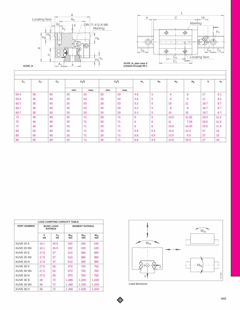
Four-row Linear RecirculatingBall Bearing And GuidewayAssemblyKUVE..S, KUVE..SN, KUVE..H SERIES
For details on part numbers, descriptive suffixes and various technical references, please refer to front of this section.For engineering or technical information contact your local sales representative or call Distributor Sales (800)523-6572 or Linear Sales (800)462-3399.
468
DIMENSION TABLE · Dimensions in mm
UNIT CARRIAGE GUIDEWAY DIMENSIONS MOUNTING DIMENSIONS
PART NUMBER PART NUMBER MASS PART NUMBER MASS CLOSING PLUGS L1) H A C A1 A2 a
–0.005
a3
kg kg/m –0.03
KUVE 20 S KWVE 20 S 0.46 TKVD 20 2.2 KA 10..A 1 ,980 30 44 69.8 12 32 20 6
KUVE 20 SN KWVE 20 SN 0.36 TKVD 20 2.2 KA 10..A 1 ,980 27 44 69.8 12 32 20 6
KUVE 25 S KWVE 25 S 0.56 TKVD 25 2.7 KA 11..A 1 ,980 36 48 81.7 12.5 35 23 6.5
KUVE 25 SN KWVE 25 SN 0.45 TKVD 25 2.7 KA 11..A 1 ,980 31 48 81.7 12.5 35 23 6.5
KUVE 25 H KWVE 25 H 0.65 TKVD 25 2.7 KA 11..A 1 980 40 48 81.7 12.5 35 23 6.5
KUVE 30 S KWVE 30 S 1.09 TKVD 30 4.3 KA 15..A 2 ,000 42 60 97.6 16 40 28 10
KUVE 30 SN KWVE 30 SN 0.87 TKVD 30 4.3 KA 15..A 2 000 38 60 97.6 16 40 28 10
KUVE 30 H KWVE 30 H 1.27 TKVD 30 4.3 KA 15..A 2 ,000 45 60 97.6 16 40 28 10
KUVE 35 S KWVE 35 S 1.6 TKVD 35 5.7 KA 15..A 2 960 48 70 110.4 18 50 34 10
KUVE 35 SN KWVE 35 SN 1.27 TKVD 35 5.7 KA 15..A 2 ,960 44 70 110.4 18 50 34 10
KUVE 35 H KWVE 35 H 1.84 TKVD 35 5.7 KA 15..A 2 ,960 55 70 110.4 18 50 34 10
1) Maximum length L of single piece guideway;longer guideways are supplied as multi-piece guideways and are marked accordingly.
2) Dimensions C5 and C6 are dependent on the guideway length L.3) If there is a possibility of settling, the fixing screws should be secured against rotation.
DIAMETERS AND TIGHTENING TORQUES FOR THREADS AND SCREWS 4)
PART NUMBER K1for screws toDIN 912-12.9
K2for screws toDIN 912-12.9
Nmmax.
Nmmax.
KUVE 20 S M5 10 M5 10
KUVE 20 SN M5 10 M5 10
KUVE 25 S M6 17 M6 17
KUVE 25 SN M6 17 M6 17
KUVE 25 H M6 17 M6 17
KUVE 30 S M8 41 M8 41
KUVE 30 SN M8 41 M8 41
KUVE 30 H M8 41 M8 41
KUVE 35 S M8 41 M8 41
KUVE 35 SN M8 41 M8 41
KUVE 35 H M8 41 M8 41
KUVE..HKUVE..H, plan view X(rotated through 90 °)
�
� � �
�������
��
��
��
���� ��� ����
�� ����
�
������ ��� ����
��
��
� �� �$$���%� ���������
��
����
���
�
����
�
����
�
��!
��#
��"!
"
#
Load directions
469
C1 C2 C4 C52) C6
2) H1 H2 H4 H6 h h1
min. max. min. max.
50.4 36 60 20 53 20 53 4.6 5 6 8 17 9.1
50.4 36 60 20 53 20 53 4.6 5 6 5 17 9.1
60.7 35 60 20 53 20 53 5.2 5 10 11 18.7 8.7
60.7 35 60 20 53 20 53 5.2 5 8 6 18.7 8.7
60.7 35 60 20 53 20 53 5.2 5 10 15 18.7 8.7
72 40 80 20 71 20 71 6 6 13.5 11.25 23.5 11.5
72 40 80 20 71 20 71 6 6 11 7.25 23.5 11.5
72 40 80 20 71 20 71 6 6 13.5 14.25 23.5 11.5
80 50 80 20 71 20 71 6.8 6.5 13.5 12.3 27 15
80 50 80 20 71 20 71 6.8 6.5 13.5 8.3 27 15
80 50 80 20 71 20 71 6.8 6.5 13.5 19.3 27 15
LOAD CARRYING CAPACITY TABLE
PART NUMBER BASIC LOADRATINGS
MOMENT RATINGS
CkN
C0kN
M0xNm
M0yNm
M0zNm
KUVE 20 S 13.1 26.9 332 240 240
KUVE 20 SN 13.1 26.9 332 240 240
KUVE 25 S 17.9 37 510 395 395
KUVE 25 SN 17.9 37 510 395 395
KUVE 25 H 17.9 37 510 395 395
KUVE 30 S 27.5 55 970 700 700
KUVE 30 SN 27.5 55 970 700 700
KUVE 30 H 27.5 55 970 700 700
KUVE 35 S 38 72 1 ,465 1 ,020 1 ,020
KUVE 35 SN 38 72 1 ,465 1,020 1 ,020
KUVE 35 H 38 72 1 ,465 1 ,020 1 ,020

Four-row Linear RecirculatingBall Bearing And Guideway AssemblyKUVE..W, KUVE..WL SERIES
For details on part numbers, descriptive suffixes and various technical references, please refer to front of this section.For engineering or technical information contact your local sales representative or call Distributor Sales (800)523-6572 or Linear Sales (800)462-3399.
470
DIMENSION TABLE · Dimensions in mm
UNIT CARRIAGE GUIDEWAY DIMENSIONS MOUNTING DIMENSIONS
PART NUMBER PART NUMBER MASS PART NUMBER MASS CLOSING PLUGS L1) H A C A1 A2 A4 A5
kg kg/m
KUVE 20 W KWVE 20 W 0.56 TKVD 20 W 5 KA 08..A 1 ,500 27 80 69.8 19 70 24 9
KUVE 25 WL KWVE 25 WL 1.46 TKVD 25 W 9.4 KA 11..A 1 ,980 35 120 107.8 25.5 107 40 14.5
KUVE 30 W KWVE 30 W 1.95 TKVD 30 W 13.6 KA 15..A 2 ,000 42 142 97.6 31 124 50 15
KUVE 35 WL KWVE 35 WL 4.11 TKVD 35 W 17.4 KA 15..A 2 ,960 50 162 140.2 36 144 60 15
1) Maximum length L of single piece guideway; longer guideways are supplied as multi-piece guideways and are marked accordingly.
2) Dimensions C5 and C6 are dependent on the guideway length L.3) When mounting from above: maximum length of fixing screw for the central fixing holes H8 +3 mm.4) If there is a possibility of settling, the fixing screws should be secured against rotation.
DIAMETERS AND TIGHTENING TORQUES FOR THREADS AND SCREWS 5)
PART NUMBER K1for screws toDIN 912-12.9
K2for screws toDIN 912-12.9
K3for screws toDIN 912-12.9
K6for screws toDIN 7984–8.8
K6for screws toDIN 912-12.9
Nmmax.
Nmmax.
Nmmax.
Nmmax.
Nmmax.
KUVE 20 W M4 5 M6 10 M5 10 M5 5.8 – –
KUVE 25 WL M6 17 M8 24 M6 17 – – M6 17
KUVE 30 W M8 41 M10 41 M8 41 M8 24 – –
KUVE 35 WL M8 41 M10 41 M8 41 – – M8 41

KUVE..WKUVE..W, plan view X(rotated through 90 °)
���� ��� ���� ��������
��
��
�
�� �� ��
���
��
�
��
��
�� ��
��� �$$���%� ��
� ��
�� ��
����
��
��!
��#
��"
!
"
#
Load directions
�� ��
�������
��
��
��
�
�
���� ��� ����
� �
�
471
a–0.005–0.030
a3 C1 C2 C4 C52) C6
2) H1 H2 H4 H5 H6 H83) h h1
–0.030min. max. min. max.
42 5 50.4 40 60 20 53 20 53 4.6 5 10 10.6 5 6 17 10
69 6.5 86.5 60 80 20 71 20 71 5.2 5 10 9.9 10 10 18.7 8.7
80 9 72 52 80 20 71 20 71 6 6 12 13.8 11.25 12 23.5 11.5
90 9 109.8 80 80 20 71 20 71 6.8 6.5 13 16.3 14.3 13 27 15
LOAD CARRYING CAPACITY TABLE
PART NUMBER BASIC LOADRATINGS
MOMENT RATINGS
CkN
C0kN
M0xNm
M0yNm
M0zNm
KUVE 20 W 13.1 26.9 687 240 240
KUVE 25 WL 23.4 54 2 ,225 825 825
KUVE 30 W 27.5 55 2 ,660 700 700
KUVE 35 WL 47.5 100 5 ,550 1 ,890 1 ,890

For details on part numbers, descriptive suffixes and various technical references, please refer to front of this section.For engineering or technical information contact your local sales representative or call Distributor Sales (800)523-6572 or Linear Sales (800)462-3399.
Linear RecirculatingBall Bearing AndGuideway AssembliesKUE SERIES
472
DIMENSION TABLE · Dimensions in mm
UNIT CARRIAGE GUIDEWAY DIMENSIONS MOUNTING DIMENSIONS
PART NUMBER PART NUMBER MASS
kg
PART NUMBER MASS
kg/m
L1) H A C A1 A2 a–0,004–0,05
a3
KUE 15 KWE 15 0.17 TKD 15 1.5 1,200 24 47 54.5 16 38 15 4.5
KUE 20 KWE 20 0.45 TKD 20 2.2 1,980 30 63 70.5 21.5 53 20 5
KUE 25 KWE 25 0.65 TKD 25 2.8 1,980 36 70 80.7 23.5 57 23 6.5
KUE 30 KWE 30 1.2 TKD 30 4.2 2,000 42 90 93 31 72 28 9
KUE 35 KWE 35 1.7 TKD 35 5.6 2,960 48 100 106.4 33 82 34 9
1) Maximum length L of single piece guideway; longer guideways are supplied as multi-piece guideways.2) Dimensions C5 and C6 are dependent on the guideway length L.3) Lubrication nipple with tapered head to DIN 71 412,
except for KUE 15 (drive fit lubrication nipple).4) A drive fit lubrication nipple and closing plug are supplied loose with the carriage.5) If there is a possibility of settling, the fixing screws should be secured against rotation.
DIAMETERS AND TIGHTENING TORQUES FOR THREADS AND SCREWS 5)
PART NUMBER K1for screws toDIN 912-12.9
K2for screws toDIN 912-12.9
K3Through holes for screws toDIN 912-12.9
K53)
Lubrication connector
Nmmax.
Nmmax.
Nmmax.
KUE 15 M4 5 M5 5.8 M4 5 NIP A14)
KUE 20 M5 10 M6 10 M5 10 NIP KE M6
KUE 25 M6 17 M8 24 M6 17 NIP KE M6
KUE 30 M8 41 M10 41 M8 41 NIP KE M6
KuE 35 M8 41 M10 41 M8 41 NIP KE M6

�
��
�
�� �� ��
�
�
��
��
�
�
���
������������
��
��
�������� ����
�
�
�
���
��� ��
�
��
Load directions
�� ��
�� ��
���
���
���
�
�
�
KUE, plan view X(rotated through 90 �)
KUE
473
ACCESSORIES
C1 C2 C3 C4 C52) C6
2) H1 H2 H4 H5 H6 h h1 CLOSING PLUGSC1 C2 C3 C4
min. max. min. max.
H1 H2 H4 H5 H6 h h1 CLOSING PLUGS
38.6 30 1.5 60 20 53 20 53 4.8 4.5 7.5 7 4 15 7.7 KA 08 TN
49.3 40 14 60 20 53 20 53 5 5 11.6 10 6.5 16.5 8.3 KA 10 TN
56.5 45 14 60 20 53 20 53 6.5 5 11.5 10 10 18 8.7 KA 11 TN
65.7 52 14 80 20 71 20 71 7 6 14.6 10 13 21.5 10 KA 15 TN
75.5 62 14 80 20 71 20 71 8 6.5 20.1 13 16 23 11.5 KA 15 TN
LOAD CARRYING CAPACITY TABLE
PART NUMBER BASIC LOAD RATINGS MOMENT RATINGS
dyn. stat.
C C0 M0x M0y M0z
kN kN Nm Nm Nm
KUE 15 6,5 9.2 73 56 56
KUE 20 13.3 18 190 154 154
KUE 25 16.2 20.9 253 185 185
KUE 30 22.5 29.7 437 335 335
KUE 35 28 37 658 450 450
For details on part numbers, descriptive suffixes and various technical references, please refer to front of this section.For engineering or technical information contact your local sales representative or call Distributor Sales (800)523-6572 or Linear Sales (800)462-3399.
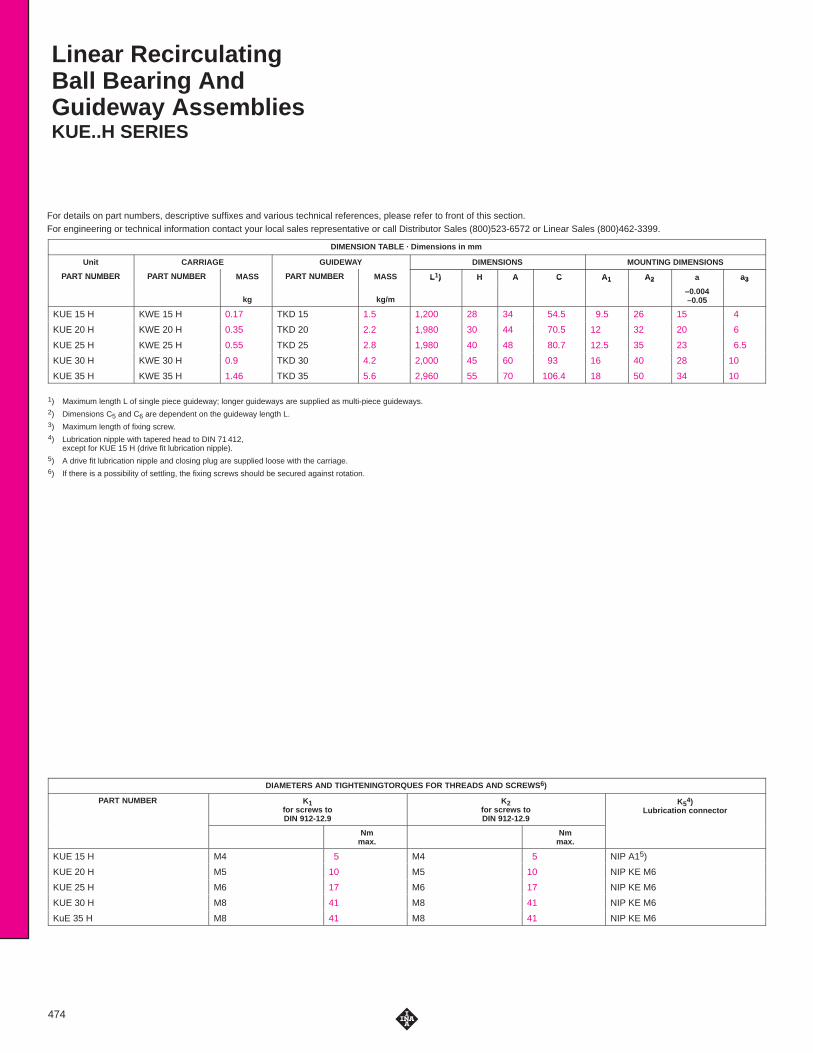
Linear RecirculatingBall Bearing AndGuideway AssembliesKUE..H SERIES
474
DIMENSION TABLE · Dimensions in mm
Unit CARRIAGE GUIDEWAY DIMENSIONS MOUNTING DIMENSIONS
PART NUMBER PART NUMBER MASS PART NUMBER MASS L1) H A C A1 A2 a a3PART NUMBER PART NUMBER
kg
PART NUMBER
kg/m
L ) H A C A1 A2
–0.004–0.05
a3
KUE 15 H KWE 15 H 0.17 TKD 15 1.5 1,200 28 34 54.5 9.5 26 15 4
KUE 20 H KWE 20 H 0.35 TKD 20 2.2 1,980 30 44 70.5 12 32 20 6
KUE 25 H KWE 25 H 0.55 TKD 25 2.8 1,980 40 48 80.7 12.5 35 23 6.5
KUE 30 H KWE 30 H 0.9 TKD 30 4.2 2,000 45 60 93 16 40 28 10
KUE 35 H KWE 35 H 1.46 TKD 35 5.6 2,960 55 70 106.4 18 50 34 10
1) Maximum length L of single piece guideway; longer guideways are supplied as multi-piece guideways.2) Dimensions C5 and C6 are dependent on the guideway length L.3) Maximum length of fixing screw.4) Lubrication nipple with tapered head to DIN 71 412,
except for KUE 15 H (drive fit lubrication nipple).5) A drive fit lubrication nipple and closing plug are supplied loose with the carriage.6) If there is a possibility of settling, the fixing screws should be secured against rotation.
DIAMETERS AND TIGHTENINGTORQUES FOR THREADS AND SCREWS 6)
PART NUMBER K1for screws toDIN 912-12.9
K2for screws toDIN 912-12.9
K54)
Lubrication connector
Nmmax.
Nmmax.
KUE 15 H M4 5 M4 5 NIP A15)
KUE 20 H M5 10 M5 10 NIP KE M6
KUE 25 H M6 17 M6 17 NIP KE M6
KUE 30 H M8 41 M8 41 NIP KE M6
KuE 35 H M8 41 M8 41 NIP KE M6

�
��
��
�
� �
��
���
���
������������
�
���������
��
�������� ����
�� �
��
����
��� ��
�
��
���� ����������
�����
�� ��
�� ��
��
��"
��!
!
"
KUE, plan view X(rotated through 90 �)
KUE..H
475
ACCESSORIES
C1 C2 C3 C4 C52) C6
2) H1 H2 H53) H6 h h1 CLOSING PLUGSC2 C3 C4
min. max. min. max.
H1 H2 H5 ) H6 h h1 CLOSING PLUGS
38.6 26 1.5 60 20 53 20 53 4.8 4.5 5 8 15 7.7 KA 08 TN
49.3 36 14 60 20 53 20 53 5 5 6.25 6.5 16.5 8.3 KA 10 TN
56.5 35 14 60 20 53 20 53 6.5 5 8 14 18 8.7 KA 11 TN
65.7 40 14 80 20 71 20 71 7 6 10 16 21.5 10 KA 15 TN
75.5 50 14 80 20 71 20 71 8 6.5 12 23 23 11.5 KA 15 TN
LOAD CARRYING CAPACITY TABLE
PART NUMBER BASIC LOAD RATINGS MOMENT RATINGS
dyn. stat.
C C0 M0x M0y M0z
kN kN Nm Nm Nm
KUE 15 H 6.5 9.2 73 56 56
KUE 20 H 13.3 18 190 154 154
KUE 25 H 16.2 20.9 253 185 185
KUE 30 H 22.5 29.7 437 335 335
KUE 35 H 28 37 658 450 450
For details on part numbers, descriptive suffixes and various technical references, please refer to front of this section.For engineering or technical information contact your local sales representative or call Distributor Sales (800)523-6572 or Linear Sales (800)462-3399.
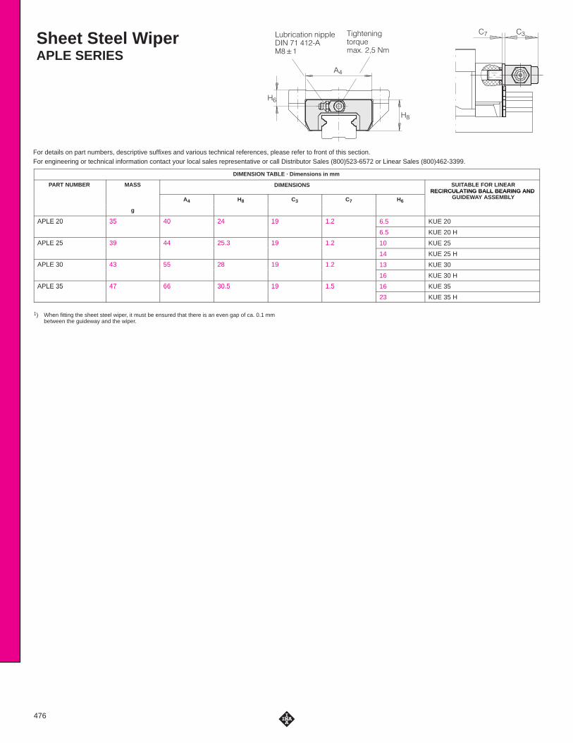
Sheet Steel WiperAPLE SERIES
�$�"���#��� �� ����� �&&���'�����
����#�����#�"!$���%� ��� ��
��
�
��
�
476
DIMENSION TABLE · Dimensions in mm
PART NUMBER MASS DIMENSIONS SUITABLE FOR LINEARRECIRCULATING BALL BEARING AND
A4 H8 C3 C7 H6
RECIRCULATING BALL BEARING AND GUIDEWAY ASSEMBLY
g
APLE 20 35 40 24 19 1.2 6.5 KUE 20APLE 20 35 40 24 19 1.2
6.5 KUE 20 H
APLE 25 39 44 25.3 19 1.2 10 KUE 25APLE 25 39 44 25.3 19 1.2
14 KUE 25 H
APLE 30 43 55 28 19 1.2 13 KUE 30APLE 30 43 55 28 19 1.2
16 KUE 30 H
APLE 35 47 66 30.5 19 1.5 16 KUE 35APLE 35 47 66 30.5 19 1.5
23 KUE 35 H
1) When fitting the sheet steel wiper, it must be ensured that there is an even gap of ca. 0.1 mmbetween the guideway and the wiper.

For details on part numbers, descriptive suffixes and various technical references, please refer to front of this section.For engineering or technical information contact your local sales representative or call Distributor Sales (800)523-6572 or Linear Sales (800)462-3399.
Lubrication Adapter PlateBPLE SERIES
�#�!���"��� ������ �� �%%���&����
����"����� "�! #���$� ��� ��
��
��
�
�
�
477
DIMENSION TABLE · Dimensions in mm
PART NUMBER MASS DIMENSIONS SUITABLE FOR LINEARRECIRCULATING BALL BEARING
A4 H8 C7 C8 H6
RECIRCULATING BALL BEARINGAND
GUIDEWAY ASSEMBLYg
GUIDEWAY ASSEMBLY
BPLE 20 25 42 23.5 12 6.5 6.5 KUE 20BPLE 20 25 42 23.5 12 6.5
6.5 KUE 20 H
BPLE 25 34 46.5 26 12 6.5 10 KUE 25BPLE 25 34 46.5 26 12 6.5
14 KUE 25 H
BPLE 30 44 58 28 12 6.5 13 KUE 30BPLE 30 44 58 28 12 6.5
16 KUE 30 H
BPLE 35 54 68 31 12 6.5 16 KUE 35BPLE 35 54 68 31 12 6.5
23 KUE 35 H
The lubrication nipple to DIN 71 412-A M8�1 can be replaced by a screw plug M8�1.
Note:In series KUE..H. the lubrication nipple protrudes about 9 mmfrom the side of the carriage.
For details on part numbers, descriptive suffixes and various technical references, please refer to front of this section.For engineering or technical information contact your local sales representative or call Distributor Sales (800)523-6572 or Linear Sales (800)462-3399.
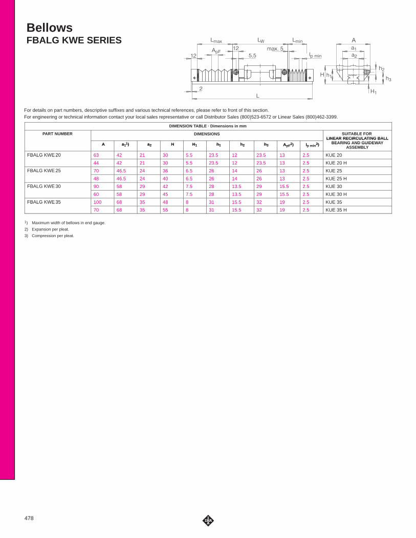
BellowsFBALG KWE SERIES
��
�
�
� �
�
�
��
��� �������
�������� �
��
� �� �
��
��
��
478
DIMENSION TABLE · Dimensions in mm
PART NUMBER DIMENSIONS SUITABLE FOR LINEAR RECIRCULATING BALL
A a11) a2 H H1 h1 h2 h3 ApF
2) lp min3)
LINEAR RECIRCULATING BALLBEARING AND GUIDEWAY
ASSEMBLYA a1
1) a2 H H1 h1 h2 h3 ApF2) lp min
3) BEARING AND GUIDEWAYASSEMBLY
FBALG KWE 20 63 42 21 30 5.5 23.5 12 23.5 13 2.5 KUE 20FBALG KWE 20
44 42 21 30 5.5 23.5 12 23.5 13 2.5 KUE 20 H
FBALG KWE 25 70 46.5 24 36 6.5 26 14 26 13 2.5 KUE 25FBALG KWE 25
48 46.5 24 40 6.5 26 14 26 13 2.5 KUE 25 H
FBALG KWE 30 90 58 29 42 7.5 28 13.5 29 15.5 2.5 KUE 30FBALG KWE 30
60 58 29 45 7.5 28 13.5 29 15.5 2.5 KUE 30 H
FBALG KWE 35 100 68 35 48 8 31 15.5 32 19 2.5 KUE 35FBALG KWE 35
70 68 35 55 8 31 15.5 32 19 2.5 KUE 35 H
1) Maximum width of bellows in end gauge.
2) Expansion per pleat.
3) Compression per pleat.

479

For details on part numbers, descriptive suffixes and various technical references, please refer to front of this section.For engineering or technical information contact your local sales representative or call Distributor Sales (800)523-6572 or Linear Sales (800)462-3399.
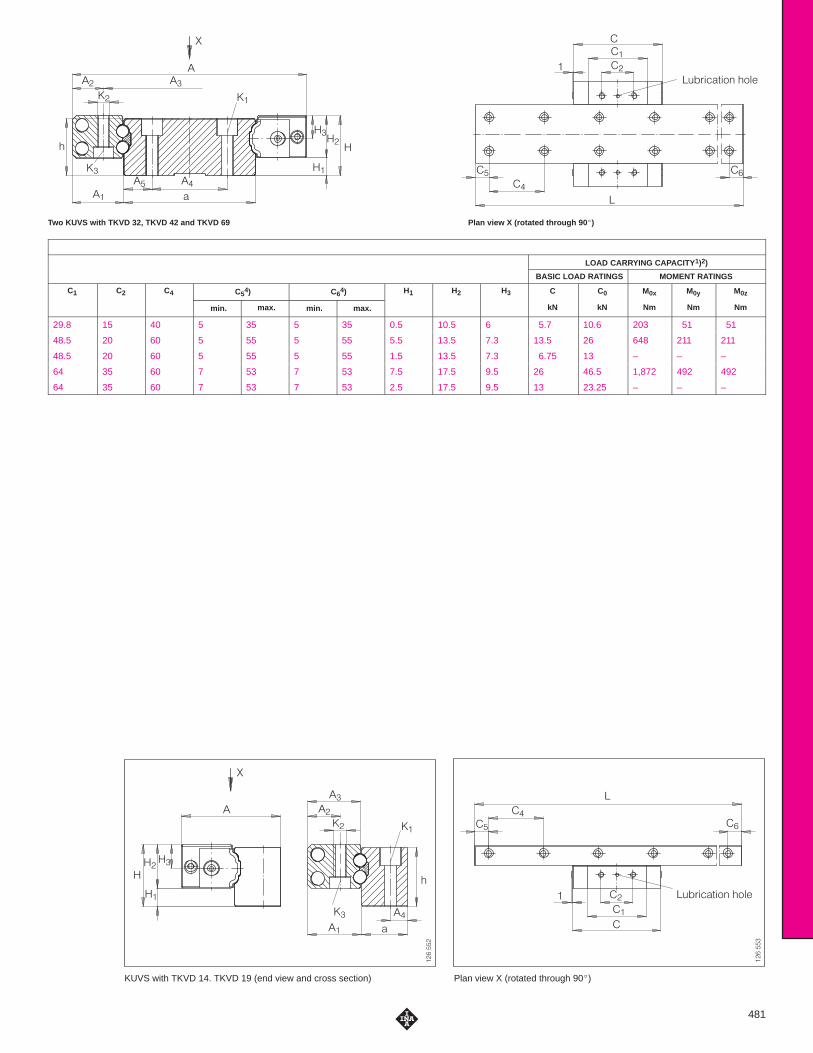
Linear Ball Bearing UnitsKUVS SERIES
GuidewaysTKVD SERIES
Load directions
�� ��
�� ��
���
���
���
�
��
480
DIMENSION TABLE · Dimensions in mm
LINEAR RECIRCULA TING GUIDEWAYS DIMENSIONS MOUNTING DIMENSIONSLINEAR RECIRCULATING BALL BEARING UNITS
GUIDEWAYS DIMENSIONS MOUNTING DIMENSIONS
PART NUMBER MASS PART NUMBER MASS CLOSING PLUGS H A C h a L3) A1 A2 A3 A4 A5
kg kg/m
) 1 2 3 4 5
KUVS 32 0.025 TKVD 32 2.3 KA 8 TN 11 51.6 47 10 31.8 2,000 9.9 5.5 40.6 18 6.9
KUVS 42 0.085 TKVD 42 5.54 KA 8 TN 19 75 71 18 42 2,000 16.5 10 55 24 9
KUVS 42 0.085 TKVD 14 1.45 KA 8 TN 15 30 71 14 13.5 1,500 16.5 10 16.2 6 –
KUVS 69 0.2 TKVD 69 12.42 KA 11 TN 25 114 96 24 69 2,000 22.5 13 88 40 14.5
KUVS 69 0.2 TKVD 19 2.66 KA 11 TN 20 42 96 19 19.5 2,000 22.5 13 22.2 8 –
1) For two linear ball bearing units with TKVD 32, TKVD 42 and TKVD 69 and for one linear ball bearing unit with TKVD 14 and TKVD 19.
2) The usable load carrying capacity is influenced by the connections between the guidance elements and the adjacent construction.
3) Maximum length L of a single piece guideway; longer guideways are supplied as multi-piece guideways and are marked accordingly.
4) Dimensions C5 and C6 are dependent on the length of the guideway;5) If there is a possibility of settling, the fixing screws should be secured against rotation.
DIAMETERS AND TIGHTENING TORQUES FOR THREADS AND SCREWS 5)
PART NUMBER K1for screws to DIN
912-12.9
K2for screws to DIN
912-12.9
K3for screws to DIN
912-12.9
Nmmax.
Nmmax.
Nmmax.
KUVS 32 M3 2.5 M3 1.5 – –
KUVS 42 M3 2.5 M4 3 M3 2.5
KUVS 69 M5 10 M6 10 M5 10
KUVS 69 M5 10 M6 10 M5 10
�
�
����
����
��
��
�� ��
�
�
�
�
�
�
����������� ����
�
�
�
�
�
Plan view X (rotated through 90�)KUVS with TKVD 14. TKVD 19 (end view and cross section)
�������
��
�
��
���
����
��
���
��
�
�������
�
��
�
�
�
�
����������� ����
Plan view X (rotated through 90 �)Two KUVS with TKVD 32, TKVD 42 and TKVD 69
481
LOAD CARRYING CAPACITY 1)2)
BASIC LOAD RATINGS MOMENT RATINGS
C1 C2 C4 C54) C6
4) H1 H2 H3 C C0 M0x M0y M0z1 2 4
min. max. min. max.
1 2 3
kN kN Nm Nm Nm
29.8 15 40 5 35 5 35 0.5 10.5 6 5.7 10.6 203 51 51
48.5 20 60 5 55 5 55 5.5 13.5 7.3 13.5 26 648 211 211
48.5 20 60 5 55 5 55 1.5 13.5 7.3 6.75 13 – – –
64 35 60 7 53 7 53 7.5 17.5 9.5 26 46.5 1,872 492 492
64 35 60 7 53 7 53 2.5 17.5 9.5 13 23.25 – – –
For details on part numbers, descriptive suffixes and various technical references, please refer to front of this section.For engineering or technical information contact your local sales representative or call Distributor Sales (800)523-6572 or Linear Sales (800)462-3399.
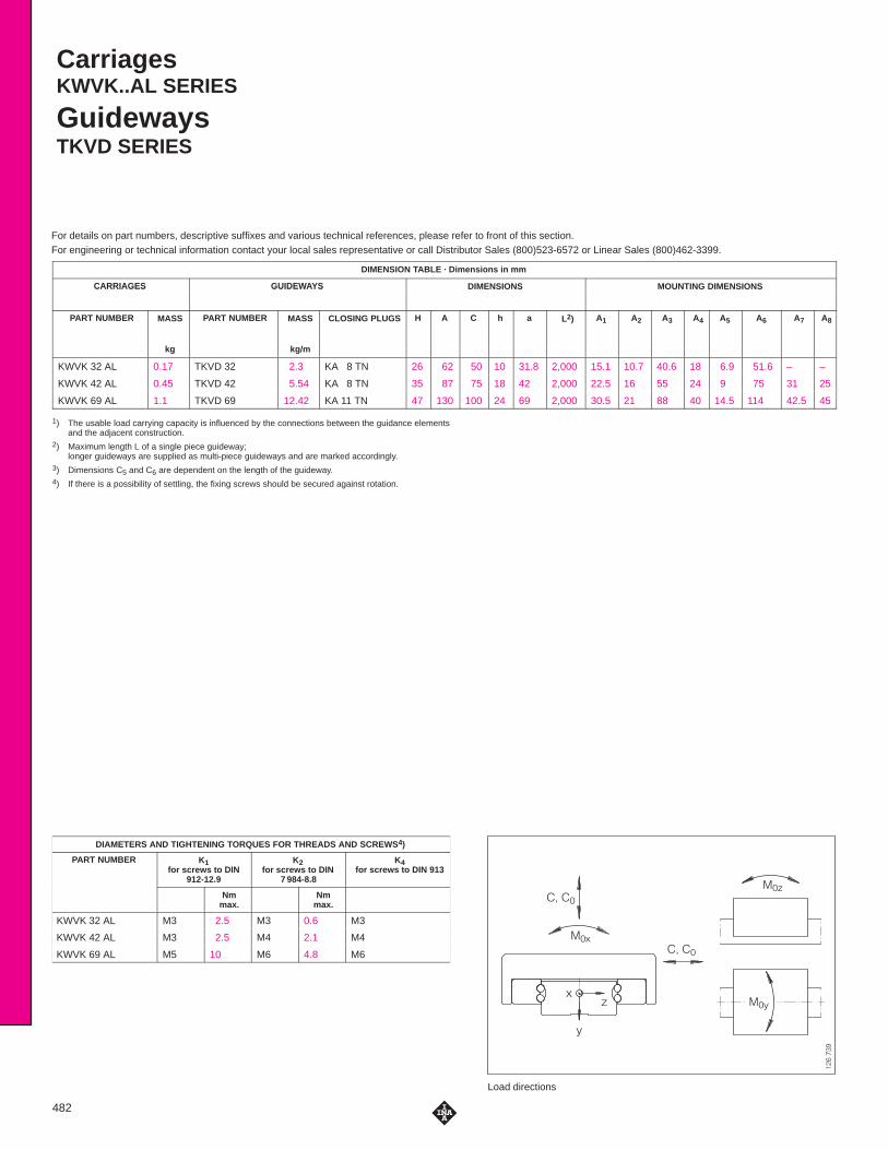
CarriagesKWVK..AL SERIES
GuidewaysTKVD SERIES
Load directions
������
� �
� �
���
���
��
�
�
482
DIMENSION TABLE · Dimensions in mm
CARRIAGES GUIDEWAYS DIMENSIONS MOUNTING DIMENSIONSCARRIAGES GUIDEWAYS
PART NUMBER MASS PART NUMBER MASS CLOSING PLUGS H A C h a L2) A1 A2 A3 A4 A5 A6 A7 A8
kg kg/m
KWVK 32 AL 0.17 TKVD 32 2.3 KA 8 TN 26 62 50 10 31.8 2,000 15.1 10.7 40.6 18 6.9 51.6 – –
KWVK 42 AL 0.45 TKVD 42 5.54 KA 8 TN 35 87 75 18 42 2,000 22.5 16 55 24 9 75 31 25
KWVK 69 AL 1.1 TKVD 69 12.42 KA 11 TN 47 130 100 24 69 2,000 30.5 21 88 40 14.5 114 42.5 45
1) The usable load carrying capacity is influenced by the connections between the guidance elementsand the adjacent construction.
2) Maximum length L of a single piece guideway; longer guideways are supplied as multi-piece guideways and are marked accordingly.
3) Dimensions C5 and C6 are dependent on the length of the guideway.4) If there is a possibility of settling, the fixing screws should be secured against rotation.
DIAMETERS AND TIGHTENING TORQUES FOR THREADS AND SCREWS 4)
PART NUMBER K1for screws to DIN
912-12.9
K2for screws to DIN
7 984-8.8
K4for screws to DIN 913
Nmmax.
Nmmax.
KWVK 32 AL M3 2.5 M3 0.6 M3
KWVK 42 AL M3 2.5 M4 2.1 M4
KWVK 69 AL M5 10 M6 4.8 M6

�
��
��
�
�
� �
���
��
��
� ��
��
�
��
��
�
�
Detail X Cross-section of carriages KWVK..AL
�����
���
��
���
��
���
�
��
����
��
�
���� � ����� �� ����� �� �
���
���
���
�����
�
�
�
�
�
� �
�
�
�
���� � �
���� �� �
���� �� �
��
��
�
�
�
�
��
Plan view X(rotated through 90 �)KWVK..AL on TKVD
483
LOAD CARRYING CAPACITY 1)
BASIC LOAD RATINGS MOMENT RATINGS
C2 C3 C4 C53) C6
3) d H1 H2 h1 C C0 M0x M0y M0z
min. max. min. max. kN kN kN kN kN
15 25 40 5 35 5 35 4.2 0.5 6 7.5 5.7 10.6 203 51 51
20 40 60 5 55 5 55 4.2 5.5 12 8 13.5 26 648 211 211
35 55 60 7 53 7 53 4.2 7.5 17 11 26 46.5 1872 412 492
For details on part numbers, descriptive suffixes and various technical references, please refer to front of this section.For engineering or technical information contact your local sales representative or call Distributor Sales (800)523-6572 or Linear Sales (800)462-3399.
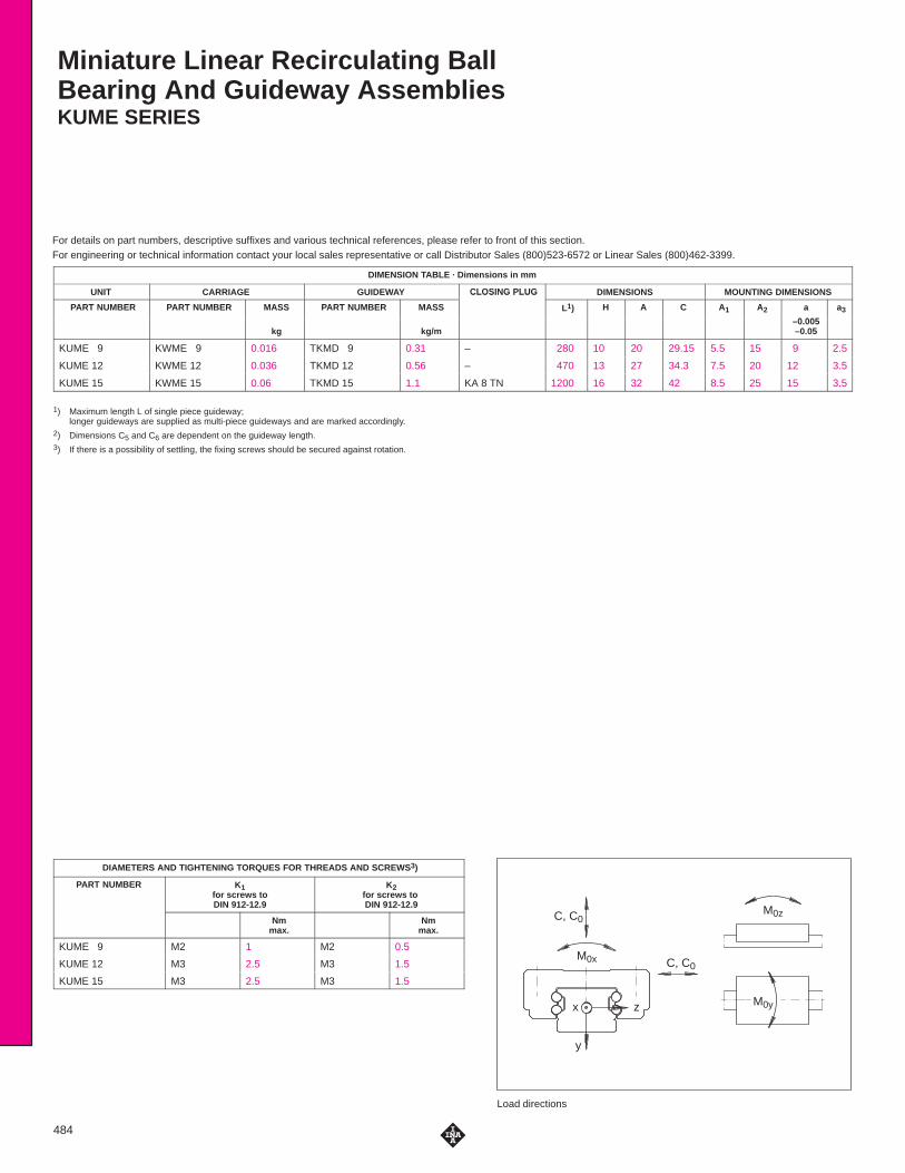
Miniature Linear Recirculating BallBearing And Guideway AssembliesKUME SERIES
Load directions
C, C0
C, C0M0x
M0z
M0yx
y
z
484
DIMENSION TABLE · Dimensions in mm
UNIT CARRIAGE GUIDEWAY CLOSING PLUG DIMENSIONS MOUNTING DIMENSIONS
PART NUMBER PART NUMBER MASS PART NUMBER MASS
CLOSING PLUG
L1) H A C A1 A2 a
0 005
a3
kg kg/m–0.005–0.05
KUME 9 KWME 9 0.016 TKMD 9 0.31 – 280 10 20 29.15 5.5 15 9 2.5
KUME 12 KWME 12 0.036 TKMD 12 0.56 – 470 13 27 34.3 7.5 20 12 3.5
KUME 15 KWME 15 0.06 TKMD 15 1.1 KA 8 TN 1200 16 32 42 8.5 25 15 3.5
1) Maximum length L of single piece guideway; longer guideways are supplied as multi-piece guideways and are marked accordingly.
2) Dimensions C5 and C6 are dependent on the guideway length.3) If there is a possibility of settling, the fixing screws should be secured against rotation.
DIAMETERS AND TIGHTENING TORQUES FOR THREADS AND SCREWS 3)
PART NUMBER K1for screws toDIN 912-12.9
K2for screws to DIN 912-12.9
Nmmax.
Nmmax.
KUME 9 M2 1 M2 0.5
KUME 12 M3 2.5 M3 1.5
KUME 15 M3 2.5 M3 1.5

H3
Hh
h1 H1
A1a
H5
Aa3A2
Locatingface
K2 X
Marking
1,5C
LC6
C1C2
C5 C4
Locating face
Marking
K1
KUME 9, KUME 12, plan view X (rotated through 90�)KUME 9, KUME 12
a
AA2
Locatingface
Marking
H5
H1h1
h
H
X K2
A1
a3
C
C4
Marking
Locating face
K1
C1
C2
C5
L
C6
KUME 15, plan view X(rotated through 90 �)
KUME 15
485
LOAD CARRYING CAPACITY
BASIC LOAD RATINGS MOMENT RATINGS
C1 C2 C4 C52) C6
2) H1 H5 h h1 C C0 M0x M0y M0z
min. max. min. max. N N Nm Nm Nm
18.35 13 20 5 15 5 15 2.25 2.5 5.5 2.5 1,340 2,060 8.8 5.8 5.8
22 15 25 5 20 5 20 3.05 3.5 7.5 3 2,150 3,200 20.8 11.3 11.3
30.6 20 40 6 34 6 34 3.5 4.0 11 4.1 3,750 6,800 65 33 33
INA SALES OFFICESMANUFACTURING PLANTS
SALES OFFICES
TORONTO, CANADA
INA Canada Inc.2871 Plymouth DriveOakville, Ontario L6H 5S5Toll Free: 800-263-4397
Telephone: 905-829-2750Fax: 905-829-2563
MONTREAL, CANADA
INA Canada Inc.149 Avenue GuthrieDorval, Quebec H9P 2P1Toll Free: 800-361-7015
Telephone: 514-631-2214Fax: 514-631-9571
VANCOUVER, CANADA
INA Canada Inc.106-1668 Derwent WayDelta, British Columbia, V3M R9Toll Free: 800-663-9006
Telephone: 604-526-3500Fax: 604-526-6544
MEXICO CITY, MEXICO
INA Mexico, S.A. de C.V.Paseo de la Reforma 383-704Col. Cuauhtemoc06500 Mexico D.F.Telephone: 525-525-00-12 / 01-84Fax: 525-525-01-94
OTHER COUNTRIES
Argentina ItalyAustralia JapanAustria KoreaBelgium NetherlandsBrazil NorwayDenmark PortugalFinland South AfricaFrance SpainGermany SwedenGreat Britain Turkey
MANUFACTURING PLANTS
PARENT COMPANY
INA Waelzlager Schaeffler oHGIndustriestrasse 1-3P.O. Box 1220D-91074 HerzogenaurachGermanyTelephone: (49132) 82-0Fax: (49132) 82 49 33
UNITED STATES
PLANT IINA USA CorporationOne INA DriveP.O. Box 390Cheraw, South Carolina 29520Telephone: 843-537-9341/9346Fax: 843-537-8751
PLANT IIINA USA CorporationHighway 9 WestP.O. Box 390Cheraw, South Carolina 29520Telephone: 843-537-9341Fax: 843-537-8752
PLANT IIIINA USA Corporation308 Springhill Farm RoadFort Mill, South Carolina 29715Telephone: 803-547-7990Fax: 803-548-8597
PLANT IVINA USA CorporationNew Cut Road, P.O. Box 570Spartanburg, South Carolina 29304Telephone: 864-583-4541Fax: 864-591-8890
PLANT VINA USA Corporation200 Evans RowCheraw, South Carolina 29520Telephone: 843-537-9341Fax: 843-537-8751
OTHER COUNTRIES
Australia Great BritainBrazil ItalyCanada KoreaChina SlovakiaFrance SpainGermany Switzerland
ATLANTA
1870 The Exchange, Suite 100Atlanta, Georgia 30339Telephone: 770-951-7015Fax: 770-951-7092
BUFFALO
336 Harris Hill Road, Suite 100Williamsville, New York 14221Telephone: 716-631-1533Fax: 716-631-8741
CHARLOTTE
377 Carowinds Boulevard, Suite 120Fort Mill, South Carolina 29708Telephone: 803-547-7970Fax: 803-548-6361
CHICAGO
2525 Cabot Drive, Suite 202Lisle, Illinois 60532Telephone: 630-955-9360Fax: 630-955-9365
CLEVELAND
12306 Woodward BoulevardGarfield Heights, Ohio 44125Telephone: 216-587-4393Fax: 216-587-2655
DALLAS
3939 Belt Line Road, Suite 365Addison, Texas 75001Telephone: 972-488-2544Fax: 972-488-2802
DAYTON
261 Regency Ridge DriveCenterville, Ohio 45459Telephone: 937-433-6404Fax: 937-433-6814
DETROIT
335 East Big Beaver Road, Suite 101Troy, Michigan 48083Telephone: 248-528-9080Fax: 248-619-2139
FLINT
771A E. Main Street, P.O. Box 666Flushing, Michigan 48433Telephone: 810-659-3607Fax: 810-659-4771
PHILADELPHIA
3399 Progress DriveBensalem, Pennsylvania 19020Telephone: 215-245-3485Fax: 215-245-7779
PHOENIX
11024 N. 28th Street, Suite 208Phoenix, Arizona 85029Telephone: 602-588–9304Fax: 602-588–9318
QUAD CITIES
300 Northwest Banktower2550 Middle Road Bettendorf, Iowa 52722Telephone: 319-355-0383Fax: 319-355-1937
RICHMOND
8003 Franklin Farms Drive, Suite 229BRichmond, Virginia 23229Telephone: 804-527-0901Fax: 804-527-0992
SAN FRANCISCO
3478 Buskirk Avenue, Suite 1043Pleasant Hill, California 94523Telephone: 925-746-7103Fax: 925-946-9936
SEATTLE
40 Lake Bellevue, Suite 100Bellevue, Washington 98005Telephone: 425-646-9477Fax: 425-646-9471
TAMPA
25327 Celmar StreetBrooksville, Florida 34601Telephone: 352-797-0620Fax: 352-797-0630
HARTFORD
1799 Farmington Ave., Bldg. B-2, P.O. Box 528Unionville, Connecticut 06085Telephone: 860-673-5236Fax: 860-673-5270
HOUSTON
10101 Southwest Freeway, Suite 400Houston, Texas 77074Telephone: 713-219-1430Fax: 713-219-1431
INDIANAPOLIS
7301 Elm Ridge RoadIndianapolis, Indiana 46236Telephone: 317-823-7268Fax: 317-823-7269
KANSAS CITY
4201 N.E. Lakewood Way, Suite 101Lee’s Summit, Missouri 64064Telephone: 816-795-9311Fax: 816-795-9322
LOS ANGELES
767 North Main StreetOrange, California 92868Telephone: 714-744-1022Fax: 714-744-2640
LOUISVILLE
14419 Micawber WayLouisville, Kentucky 40245Telephone: 502-254-9590Fax: 502-254-2760
MEMPHIS
1922 Exeter Road, Suite 20Germantown, Tennessee 38138Telephone: 901-756-0023Fax: 901-756-0260
MILWAUKEE
N16 W23233 Stoneridge Drive, Suite 220Waukesha, Wisconsin 53188Telephone: 414-544-8270Fax: 414-544-8271
MINNEAPOLIS
80 W. 78th Street, Suite 270CChanhassen, Minnesota 55317Telephone: 612-934-8822Fax: 612-934-8833
USA SALES OFFICES
Corporate OfficesINA USA CORPORATION308 Springhill Farm Road
Fort Mill, South Carolina 29715Telephone: 803-548-8500 Fax: 803-548-8599
INA LINEAR TECHNIKA Division Of INA USA Corporation
247 Rittenhouse CircleBristol, Pennsylvania 19007
Telephone: 215-781-6900 Fax: 215-781-9830


