24
Doc. no.CE*-OMD0004-E PRODUCT NAME MONOSASHI-KUN MODEL / Series / Product Number CE1* Series
Doc. no.CE*-OMD0004-E
PRODUCT NAME
MONOSASHI-KUN
MODEL / Series / Product Number
CE1* Series
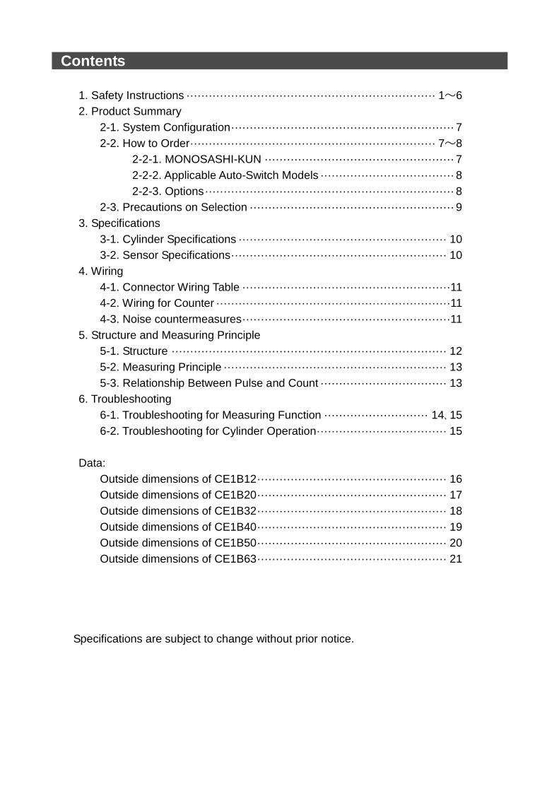
Contents
1. Safety Instructions ··································································· 1~6
2. Product Summary
2-1. System Configuration ···························································· 7
2-2. How to Order ·································································· 7~8
2-2-1. MONOSASHI-KUN ··················································· 7
2-2-2. Applicable Auto-Switch Models ···································· 8
2-2-3. Options ··································································· 8
2-3. Precautions on Selection ······················································· 9
3. Specifications
3-1. Cylinder Specifications ························································ 10
3-2. Sensor Specifications ·························································· 10
4. Wiring
4-1. Connector Wiring Table ························································11
4-2. Wiring for Counter ·······························································11
4-3. Noise countermeasures ························································11
5. Structure and Measuring Principle
5-1. Structure ·········································································· 12
5-2. Measuring Principle ···························································· 13
5-3. Relationship Between Pulse and Count ·································· 13
6. Troubleshooting
6-1. Troubleshooting for Measuring Function ···························· 14、15
6-2. Troubleshooting for Cylinder Operation ··································· 15
Data:
Outside dimensions of CE1B12 ··················································· 16
Outside dimensions of CE1B20 ··················································· 17
Outside dimensions of CE1B32 ··················································· 18
Outside dimensions of CE1B40 ··················································· 19
Outside dimensions of CE1B50 ··················································· 20
Outside dimensions of CE1B63 ··················································· 21
Specifications are subject to change without prior notice.
- 1 -
CE1 Series/MONOSASHI-KUN
1.Safety Instructions These safety instructions are intended to prevent hazardous situations and/or equipment damage. These instructions indicate the level of potential hazard with the labels of “Caution,” “Warning” or “Danger.” They are all important notes for safety and must be followed in addition to International Standards (ISO/IEC)*1) , and other safety regulations. *1) ISO 4414: Pneumatic fluid power -- General rules relating to systems. ISO 4413: Hydraulic fluid power -- General rules relating to systems. IEC 60204-1: Safety of machinery -- Electrical equipment of machines .(Part 1: General requirements) ISO 10218: Manipulating industrial robots -Safety. etc.
Caution Caution indicates a hazard with a low level of risk which, if not avoided, could result
in minor or moderate injury.
Warning Warning indicates a hazard with a medium level of risk which, if not avoided, could
result in death or serious injury.
Danger Danger indicates a hazard with a high level of risk which, if not avoided, will result in death or serious injury.
Warning 1. The compatibility of the product is the responsibility of the person who designs the equipment or
decides its specifications. Since the product specified here is used under various operating conditions, its compatibility with specific equipment must be decided by the person who designs the equipment or decides its specifications based on necessary analysis and test results. The expected performance and safety assurance of the equipment will be the responsibility of the person who has determined its compatibility with the product. This person should also continuously review all specifications of the product referring to its latest catalog information, with a view to giving due consideration to any possibility of equipment failure when configuring the equipment.
2. Only personnel with appropriate training should operate machinery and equipment. The product specified here may become unsafe if handled incorrectly. The assembly, operation and maintenance of machines or equipment including our products must be performed by an operator who is appropriately trained and experienced.
3. Do not service or attempt to remove product and machinery/equipment until safety is confirmed. 1.The inspection and maintenance of machinery/equipment should only be performed after measures to
prevent falling or runaway of the driven objects have been confirmed. 2.When the product is to be removed, confirm that the safety measures as mentioned above are implemented and the power from any appropriate source is cut, and read and understand the specific product precautions of all relevant products carefully. 3. Before machinery/equipment is restarted, take measures to prevent unexpected operation and malfunction.
4. Contact SMC beforehand and take special consideration of safety measures if the product is to be used in any of the following conditions. 1. Conditions and environments outside of the given specifications, or use outdoors or in a place exposed to direct sunlight. 2. Installation on equipment in conjunction with atomic energy, railways, air navigation, space, shipping,
vehicles, military, medical treatment, combustion and recreation, or equipment in contact with food and beverages, emergency stop circuits, clutch and brake circuits in press applications, safety equipment or other applications unsuitable for the standard specifications described in the product catalog.
3. An application which could have negative effects on people, property, or animals requiring special safety analysis.
4.Use in an interlock circuit, which requires the provision of double interlock for possible failure by using a mechanical protective function, and periodical checks to confirm proper operation.
- 2 -
CE1 Series/MONOSASHI-KUN 1.Safety Instructions
Caution 1. The product is provided for use in manufacturing industries.
The product herein described is basically provided for peaceful use in manufacturing industries. If considering using the product in other industries, consult SMC beforehand and exchange specifications or a contract if necessary.
If anything is unclear, contact your nearest sales branch.
Limited warranty and Disclaimer/Compliance Requirements The product used is subject to the following “Limited warranty and Disclaimer” and “Compliance Requirements”. Read and accept them before using the product.
Limited warranty and Disclaimer
1.The warranty period of the product is 1 year in service or 1.5 years after the product is
delivered,whichever is first.2) Also, the product may have specified durability, running distance or replacement parts. Please consult your nearest sales branch.
2. For any failure or damage reported within the warranty period which is clearly our responsibility, a replacement product or necessary parts will be provided. This limited warranty applies only to our product independently, and not to any other damage
incurred due to the failure of the product. 3. Prior to using SMC products, please read and understand the warranty terms and disclaimers
noted in the specified catalog for the particular products.
2) Vacuum pads are excluded from this 1 year warranty. A vacuum pad is a consumable part, so it is warranted for a year after it is delivered.
Also, even within the warranty period, the wear of a product due to the use of the vacuum pad or failure due to the deterioration of rubber material are not covered by the limited
warranty. Compliance Requirements
1. The use of SMC products with production equipment for the manufacture of weapons of mass destruction(WMD) or any other weapon is strictly prohibited.
2. The exports of SMC products or technology from one country to another are governed by the relevant security laws and regulation of the countries involved in the transaction. Prior to the shipment of a SMC product to another country, assure that all local rules governing that export are known and followed.
Caution SMC products are not intended for use as instruments for legal metrology.
Measurement instruments that SMC manufactures or sells have not been qualified by type approval tests relevant to the metrology (measurement) laws of each country.
Therefore, SMC products cannot be used for business or certification ordained by the metrology
(measurement) laws of each country.
The product is provided for use in manufacturing industries. The product herein described is basically provided for peaceful use in manufacturing industries. If considering using the product in other industries, consult SMC beforehand and exchange specifications or a contract if necessary. 契約などを行ってください。
The product is provided for use in manufacturing industries. The product herein described is basically provided for peaceful use in manufacturing industries. If considering using the product in other industries, consult SMC beforehand and exchange specifications or a contract if necessary. 契約などを行ってください。
! Caution
SMC products are not intended for use as instruments for legal metrology.
Measurement instruments that SMC manufactures or sells have not been qualified by type approval tests relevant to the metrology (measurement) laws of each country. Therefore, SMC products cannot be used for business or certification ordained by the metrology (measurement) laws of each country.
- 3 -
Warning
1. The compatibility of pneumatic equipment is the responsibility of the person who designs the
pneumatic system or decides its specifications.
Since the products specified here are used in various operating conditions, their compatibility for the
specific pneumatic system must be based on specificitions or after analysis and/or tests to meet
your specific requirements. Ensuring the initial performance and safety are the responsibility of the
person who decides the compatibility of pneumatic system. Pneumatic systems should be constructed
after full review on the details of the products other than specifications and possibilities of failures by
checking the latest product information.
2. Only trained personnel should operate pneumatically operated machinery and equipment.
Assembly, handling or repair of pneumatic systems should be performed by trained and experienced
operators.
3. Do not service machinery/ equipment or attempt to remove component until safety is confirmed.
a.Inspection and maintenance of machinery/ equipment should only be perfomed after confirmation of
safe locked-out control positions.
b)When equipment is to be removed, confirm the safety process as mentioned above. Cut the supply
pressure for this equipment and exhaust all residual compressed air in the system.
c)Before machinery/ equipment is re-started, take measures to prevent shooting-out of cylinder piton
rod etc.
4. Contact SMC and take necessary safety measures if the products are to be used in any of the
following conditions.
a)Conditions and environments beyond the given specifications, or if products are used outdoors.
b)Installation on equipment in conjunction with atomic energy, railway, air navigation, vehicles,
medical equipment, food and beverage, recreation equipment, emergency stop circuits, press
applications, or safety equipment.
c)An application which has the possibility of having negative effects on people, property, or animals,
requiring special safety analysis.
!

- 4 -
Operating and Storage Environments
Warning
1. Envionments to avoid
Avoid using or storing the products in the
following environments which may cause failures.
If the products need to be used or stored in those
environments, take necessary measures.
a. Place where ambient temperature exceeds the
range of 0℃ to 60℃.
b. Place where ambient humidity exceeds the
range of 25% to 85% RH.
c. Place where condensation occurs due to
sudden temperature change.
d. Place where atmosphere containing corrosive
gas, flammable gas or organic solvent.
e. Place where atmosphere containing
con-ductive powder such as dust and iron
chips, oil mist, salt, or organic solvent, or
splashing cutting chips, dust and cutting oil
(water , liquid) over the products.
f. Place where the products are exposed to
direct sunlight or radiated heat.
g. Place where strong electromagnetic noise is
generated (place where strong electric field,
strong magnetic field or surge is generated).
h. Place where static electricity is discharged or
condition that the products have electrostatic
discharge.
i. Place where strong high frequency is
gene-rated.
j. Place where damages of thunder are expected.
k. Place where vibration or impact is directly
given to the products.
l. Condition that the products are deformed by
force or weight applied.
2. Do not close any objects which are affected by
magnets.
Since magnets are built in cylinders, do not close
magnetic disks, magnetic cards or magnetic tapes.
The data may be destroyed.
Precautions on Design
Warning 1. Theire is a possibility of dangerous sudden
action by cylindres if sliding parts of
machi-nery are twisted due to external
forces,etc.
In such cases, human injury may occur: e. g., by
catching hands or feet in the machinery, or
damage to the machinery itself may occur.
2. Provide a cover to minimize the risk of human
injury.
When a driven object or moving parts of a cylinder
may cause the risk of human injury, design a
structure to avoid contact with human body.
3. Securely tighten all stationary parts and
connected parts of cylinders so that they will
not become loose.
Tighten cylinders securely especially when they
are used in high frequency or in locations where
direct vibration or impact shock, etc. will be
applied to the body of the cylinder.
4. Deceleration circuits or shock absorvers are
needed in some cases.
If a driven object travels at a high speed or is
heavy, impact will not be sufficiently absorved only
with the cylinder chshion. In such cases, use a
circuit to decelerate the cylinder speed before the
cushion becomes effective or use external shock
absorvers to reduce impact. At this time, take the
rigidity of machinery into account.
5. Consider possible drop of pressure in circuit
due to power outage.
For cylinders used in clamping mechanism, a
work may become loose due to less clamping
force by pressure drop in circuit at the time of
power outage. Install safety devices to prevent
human injury and machinery damage. Measures
should be taken to prevent drop of hanging or
lifing equipment.
6. Consider possible loss of power sources.
Measures should be taken to protect against
human injury and machinery damage in the event
that there is a loss of air pressure, electricity or
hydraulic power.
7. Design circuit to prevent shooting out of a
driven object.
A driven object is quickly shot out when pressure
is supplied from one side of the piston after air in
the cylinder is exhausted in such cases that
cylinder is actuated by exhaust center type of
directional control valve or started after residual air
is exhausted from the circuit. At time, human injury
may occur; e.g., by catching hands or feet in the
machinery, or damage to the machinery itself may
occur. Therefore, the machine should be designed
and constructed to prevent shooting out.
8. Consider emergency stops.
Design the machinery so that human injury and/or
damage to machinery and equipment will not be
caused when machinery is stopped by a safety
device under abnormal conditions, a power
outage or a manual emergency stop.
9. Consider actions when operation is restarted
after an emergency stop or abnormal stop.
Design the machinery so that human injury or
equipment demage will not occur upon restart of
operation. When the cylinder is required to return
to the initial position, provide the equipment with a
safe override.
!
!
- 5 -
Selection
Warning 1. Confirm the specifications.
The product in this manual is designed to be used
only industrial compressed air system. The
product should not be used with pressures or
temperatures outside the range of the
specifications, as this may cause damage or
malfunction, etc.
2. Intermediate stop.
When cylinder piston is stopped intermediately by
3-position closed center type of directional control
valve, intermediate stop positions may not be as
precise and exact as hydraulic operation due to
compressibility of air. Valve and cylinders are not
guaranteed for zero air leakage, and stop position
may not be held in a long period of time. Consult
SMC for long term holding of stop positions.
Caution 1. Mount speed controller and adjust cylinder
operaiton speed gradually from low speed to
a desired speed.
Air Supply
Warning 1. Do not use the product out of the specified
ranges for pressure and temperature to
pre-vent equipment damage and mal-function.
①Operating pressure:
12 : 0.07 to 1.0 MPa
20~φ63 : 0.05 to 1.0 MPa
②Fluid & ambient temperature: 0 to 60C
2. Use clean air.
Do not use the product with compressed air
includes chemicals, synthetic materials (including
organic solvents), salinity, corrosive gases, etc.,
as this may cause damage or malfunction.
Caution 1. Install air filter.
Install air filter before and in vicinity of valve. The
filter should be able to collect particles of 5
microns or smaller. A large quantity of drain may
cause malfunction of pneumatic components.
2. Install after cooler, air dryer, auto drain, etc.
Compressed air that includes excessive
condensate may cause malfunction of valve and
other pneumatic equipment. To prevent this,
install after cooler, air dryer, auto drain, etc.
Installation
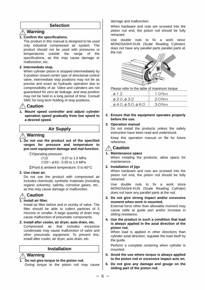
Warning 1. Do not give torque to the piston rod.
Giving torque to the piston rod may cause
damage and malfunction.
When hardware and nuts are screwed into the
piston rod end, the piston rod should be fully
retracted.
Use double nuts to fix a work since
MONOSASHI-KUN (Scale Reading Cylinder)
does not have any parallel parts parallel parts at
the rod.
Please refer to the table of maximum torque
φ12 10Nm
φ20,φ32 20Nm
φ40,φ50,φ60 30Nm
2. Ensure that the equipment operates properly
before the use.
3. Operation manual
Do not install the products unless the safety
instruction have been read and understood.
Keep this operation manual on file for future
reference.
Caution 1. Maintenance space
When instaling the products, allow space for
maintenance.
2. Installation of jigs
When hardware and nuts are screwed into the
piston rod end, the piston rod should be fully
retracted.
Use double nuts to fix a work since
MONOSASHI-KUN (Scale Reading Cylinder)
does not have any parallel parts at the rod.
3. Do not give strong impact and/or excessive
moment when work is mounted.
External force other than allowable moment may
cause rattle at guide part and/or increase in
sliding resistance.
4. Use the product in such a condition that load
is always applied in the axial direction of the
piston rod.
When load is applied in other directions than
cylinder axial direction, regulate the load itself by
the guide.
Perform a complete centering when cylinder is
mounted.
5. Avoid the use where torque is always applied
to the piston rod or excessive impact acts on.
6. Do not give any damage and gouge on the
sliding part of the piston rod.
!
!
!
!
!
!
- 6 -
Wiring
Warning 1. Preparation for wiring
Shut off the power before wiring (including
insertion and removal of connectors). Mount a
protective cover on the terminal block after wiring.
2. Check the power
Make sure the power has sufficient capacity and
voltages are within the specified range before
wiring.
3. Grounding
Ground terminal block F.G. (Frame Ground).
Do not ground it with devices generating strong
electromagnetic noise.
4. Check wiring
Incorrect wiring may cause damage or
malfunction of the products. Make sure the wiring
is correct before operation.
Caution 1. Separation of signal wires from power wire.
Avoid common or parallel wiring of signal and
power wires to prevent malfunction due to noise.
2. Wiring arrangement and fixation
Avoid bending cables sharply at connector part or
electrical entry in wiring arrangement.
Inproper arrangement may cause disconnection
which in turn causes malfunction. Fix cables
close enough not to give excessive force to the
connector.
Piping
Caution 1. Before piping
Remove cutting chips, cutting oil, dust, etc. in
piping by flushing or cleaning before piping. Care
should be taken especially that any cutting chips,
cutting oil, dust, etc. do not exist after a filter.
2. At piping
①Foreign matter should not enter. Entering of
foreign matter will cause malfunction.
②Cutting chips and sealing materials at piping
threads should not enter valves when piping
and fittings are screwed in. Leave 1.5 to 2
threads when seal tape is used.
Lubrication
Caution 1. Lubrication of cylinder
①This cylinder is pre-lubricated and can be used
without lubrication.
②In case of lubrication, use a equivalent of the
turbine oil type 1 ISO VG32. Once lubrication is
performed, it should be continued since the
initial lubricant flows out causing malfunction.
Sensor Unit
Caution 1. Do not remove the sensor unit.
The position and sensitivity of the sensor is
adjusted properly. Removing or replacing the
sensor may cause malfunction.
2. External magnetic field should be 14.5mT or
less.
Strong magnetic field in the vicinity may cause
malfunction since CEP1 sensor is magnetic type.
3. Do not pull sensor cable strongly.
Such action may cause failure.
4. Power supply line
Do not mount any switch or relay to power supply
line (12 VDC to 24 VDC).
Measurement
Caution SMC products are not intended for use as
instruments for legal metrology.
Measurement instruments that SMC manufactures
or sells have not been qualified by type approval
tests relevant to the metrology (measurement) laws
of each country. Therefore, SMC products cannot be
used for business or certification ordained by the
metrology (measurement) laws of each country.
Maintenance and Check
Caution 1. Performing regular check
Check regularly that the products do not operate
with failures unsolved. Check should be done by
trained and experienced operators.
2. Dismantling of product and supply/exhaust of
compressed air.
Before dismantling, ensure that drop preventing
and runaway preventing treatments are properly
provided, shut the power source of air supplied,
and exhausts compressed air in the system.
When starting operation again, operate the
product with care after ensuring that a treatment
for preventing extrusion is properly provided.
3. Prohibition of disassembly and modification.
To prevent accidents such as failures and electric
shocks, do not remove the cover to perform
disassembly or modification. If the cover has to
be removed, shut off the power before removal.
4. Disposal
Request a special agent for handling industrial
waste to dispose the products.
!
!
!
!
!
! !
- 7 -
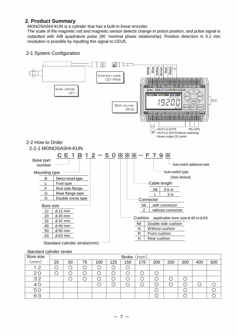
2. Product Summary MONOSASHI-KUN is a cylinder that has a built-in linear encoder. The scale of the magnetic rod and magnetic sensor detects change in piston position, and pulse signal is
outputted with A/B quadrature pulse (90 ゚ nominal phase relationship). Position detection in 0.1 mm
resolution is possible by inputting this signal to CEU5.
2-1 System Configuration
2-2 How to Order
2-2-1 MONOSASHI-KUN
CE1B12-50※※※-F79※ Base part
number
Bore size
Nil 0.5 m
L 3 m
B Direct mount type
L Foot type
F Rod side flange
G Rear flange type
D Double crevis type
12 φ12 mm
20 φ20 mm
32 φ32 mm
40 φ40 mm
50 φ50 mm
63 φ63 mm
Cable length
Mounting type
Standard cylinder stroke(mm)
Nil with connector
Z without connector
Connector
Auto-switch type
(See below)
Auto-switch additional mark
Nil Double side cushion
N Without cushion
R Front cushion
H Rear cushion
Cushion applicable bore sizeφ40 toφ63.
Standard cylinder stroke
Bore size
(mm) Stroke(mm)
25 50 75 100 125 150 175 200 250 300 400 500
12 ○ ○ ○ ○ ○ ○
20 ○ ○ ○ ○ ○ ○ ○ ○
32 ○ ○ ○ ○ ○ ○ ○ ○ ○
40 ○ ○ ○ ○ ○ ○ ○ ○ ○
50 ○ ○ ○
63 ○ ○ ○
White
Blu
e
Yello
w
Bro
wn
Red
Bla
ck
Multi counter
CEU5
Scale cylinder
CE1
Extension cable
CE1-R※※
・OUT1 to OUT5 RS-232C
・OUT1 to OUT20 (Bank switching)
・Binary output (31 point)
- 8 -
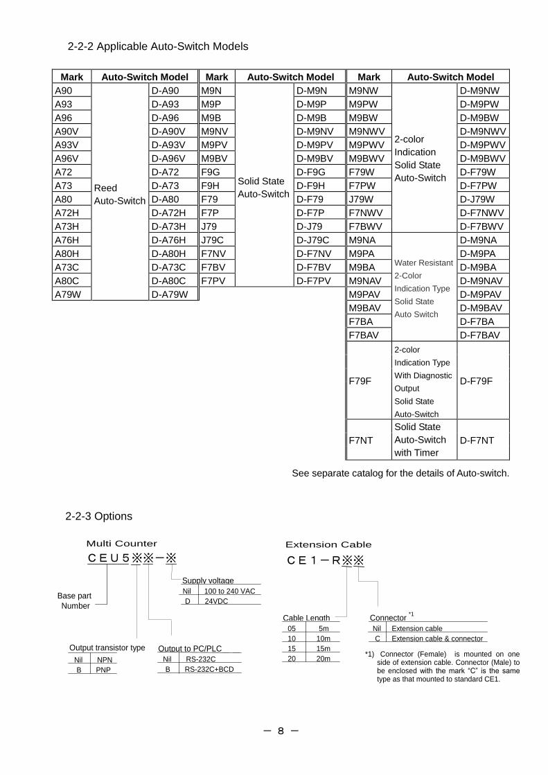
2-2-2 Applicable Auto-Switch Models
Mark Auto-Switch Model Mark Auto-Switch Model Mark Auto-Switch Model
A90
Reed
Auto-Switch
D-A90 M9N
Solid State
Auto-Switch
D-M9N M9NW
2-color
Indication
Solid State
Auto-Switch
D-M9NW
A93 D-A93 M9P D-M9P M9PW D-M9PW
A96 D-A96 M9B D-M9B M9BW D-M9BW
A90V D-A90V M9NV D-M9NV M9NWV D-M9NWV
A93V D-A93V M9PV D-M9PV M9PWV D-M9PWV
A96V D-A96V M9BV D-M9BV M9BWV D-M9BWV
A72 D-A72 F9G D-F9G F79W D-F79W
A73 D-A73 F9H D-F9H F7PW D-F7PW
A80 D-A80 F79 D-F79 J79W D-J79W
A72H D-A72H F7P D-F7P F7NWV D-F7NWV
A73H D-A73H J79 D-J79 F7BWV D-F7BWV
A76H D-A76H J79C D-J79C M9NA
Water Resistant
2-Color
Indication Type
Solid State
Auto Switch
D-M9NA
A80H D-A80H F7NV D-F7NV M9PA D-M9PA
A73C D-A73C F7BV D-F7BV M9BA D-M9BA
A80C D-A80C F7PV D-F7PV M9NAV D-M9NAV
A79W D-A79W M9PAV D-M9PAV
M9BAV D-M9BAV
F7BA D-F7BA
F7BAV D-F7BAV
F79F
2-color
Indication Type
With Diagnostic
Output
Solid State
Auto-Switch
D-F79F
Solid State
Auto-Switch
with Timer
F7NT D-F7NT
See separate catalog for the details of Auto-switch.
2-2-3 Options
CEU5※※-※
Output to PC/PLC
Supply voltage
Nil 100 to 240 VAC
D 24VDC
Nil RS-232C
B RS-232C+BCD
Multi Counter
Base part
Number
Output transistor type
Nil NPN
B PNP
CE1-R※※
Cable Length Connector *1
Nil Extension cable
C Extension cable & connector
05 5m
10 10m
15 15m
20 20m
Extension Cable
*1) Connector (Female) is mounted on one side of extension cable. Connector (Male) to be enclosed with the mark “C” is the same type as that mounted to standard CE1.
- 9 -
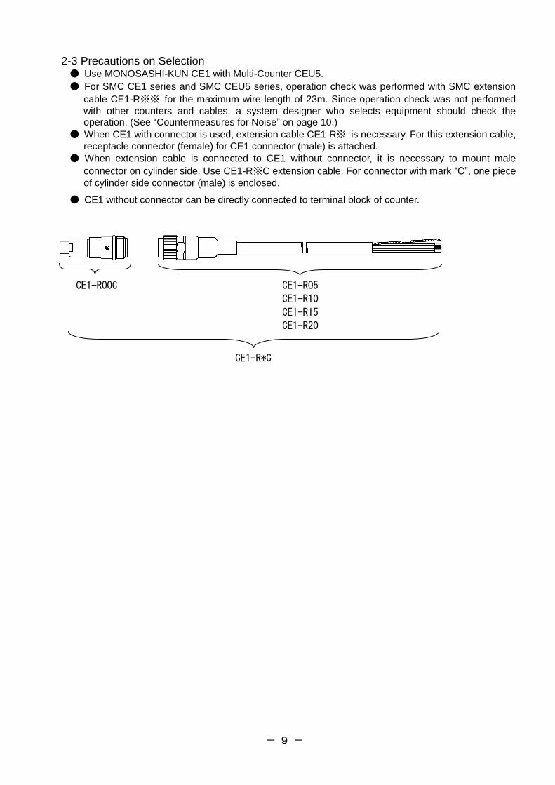
2-3 Precautions on Selection ● Use MONOSASHI-KUN CE1 with Multi-Counter CEU5.
● For SMC CE1 series and SMC CEU5 series, operation check was performed with SMC extension
cable CE1-R※※ for the maximum wire length of 23m. Since operation check was not performed
with other counters and cables, a system designer who selects equipment should check the operation. (See “Countermeasures for Noise” on page 10.)
● When CE1 with connector is used, extension cable CE1-R※ is necessary. For this extension cable,
receptacle connector (female) for CE1 connector (male) is attached.
● When extension cable is connected to CE1 without connector, it is necessary to mount male
connector on cylinder side. Use CE1-R※C extension cable. For connector with mark “C”, one piece
of cylinder side connector (male) is enclosed.
● CE1 without connector can be directly connected to terminal block of counter.
CE1-ROOC CE1-RO5
CE1-R10
CE1-R15
CE1-R20
CE1-R*C
- 10 -
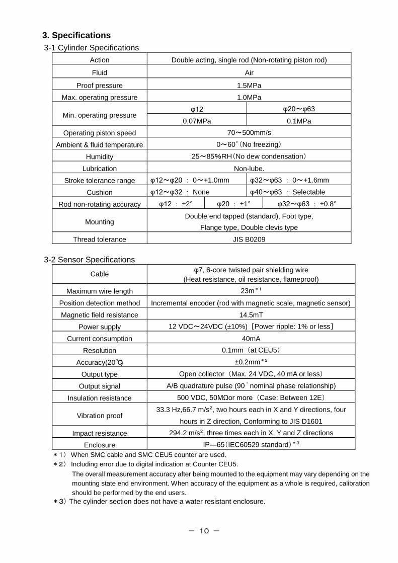
3. Specifications
3-1 Cylinder Specifications
Action Double acting, single rod (Non-rotating piston rod)
Fluid Air
Proof pressure 1.5MPa
Max. operating pressure 1.0MPa
Min. operating pressure φ12 φ20~φ63
0.07MPa 0.1MPa
Operating piston speed 70~500mm/s
Ambient & fluid temperature 0~60゜(No freezing)
Humidity 25~85%RH(No dew condensation)
Lubrication Non-lube.
Stroke tolerance range φ12~φ20 : 0~+1.0mm φ32~φ63 : 0~+1.6mm
Cushion φ12~φ32 : None φ40~φ63 : Selectable
Rod non-rotating accuracy φ12 : ±2° φ20 : ±1° φ32~φ63 : ±0.8°
Mounting Double end tapped (standard), Foot type,
Flange type, Double clevis type
Thread tolerance JIS B0209
3-2 Sensor Specifications
Cable φ7, 6-core twisted pair shielding wire
(Heat resistance, oil resistance, flameproof)
Maximum wire length 23m*1
Position detection method Incremental encoder (rod with magnetic scale, magnetic sensor)
Magnetic field resistance 14.5mT
Power supply 12 VDC~24VDC (±10%) [Power ripple: 1% or less]
Current consumption 40mA
Resolution 0.1mm (at CEU5)
Accuracy(20℃) ±0.2mm*2
Output type Open collector (Max. 24 VDC, 40 mA or less)
Output signal A/B quadrature pulse (90 ゚ nominal phase relationship)
Insulation resistance 500 VDC, 50MΩor more (Case: Between 12E)
Vibration proof 33.3 Hz,66.7 m/s2, two hours each in X and Y directions, four
hours in Z direction, Conforming to JIS D1601
Impact resistance 294.2 m/s2, three times each in X, Y and Z directions
Enclosure IP―65(IEC60529 standard)*3
*1) When SMC cable and SMC CEU5 counter are used.
*2) Including error due to digital indication at Counter CEU5.
The overall measurement accuracy after being mounted to the equipment may vary depending on the
mounting state end environment. When accuracy of the equipment as a whole is required, calibration
should be performed by the end users.
*3)The cylinder section does not have a water resistant enclosure.
- 11 -
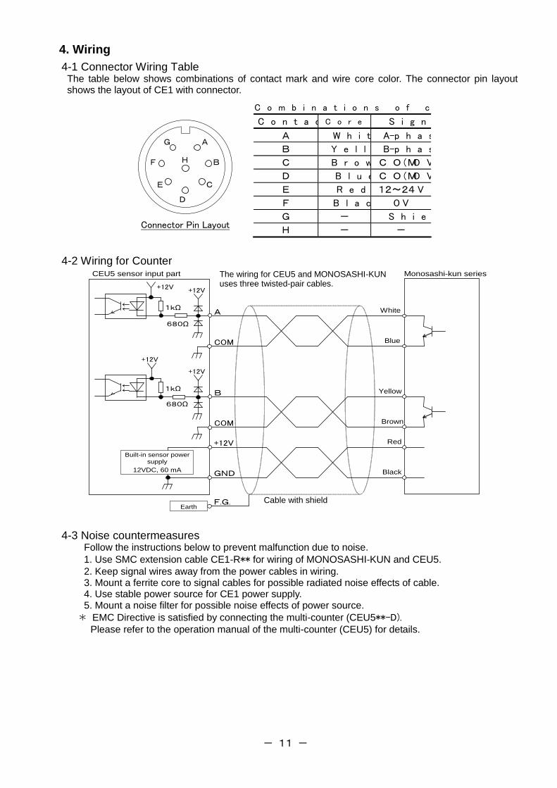
4. Wiring
4-1 Connector Wiring Table The table below shows combinations of contact mark and wire core color. The connector pin layout shows the layout of CE1 with connector.
A
B
C
D
E
F
G
H
Connector Pin Layout
C o m b i n a t i o n s o f c o n t a c t m a r k a n d c o r e c o l o r
C o n t a c t M a r k C o r e C o l o r S i g n a l
A W h i t e A-p h a s e
B Y e l l o w B-p h a s e
C B r o w n C O M( O V )
D B l u e C O M( O V )
E R e d 12~24 V
F B l a c k 0 V
G - S h i e l d
H - -
4-2 Wiring for Counter Monosashi-kun series
White
Blue
Yellow
Brownn
Red
Black
A
B
COM
COM
+12V
GND
F.G. Earth
CEU5 sensor input part
1kΩ
+12V +12V
680Ω
1kΩ
+12V
+12V
680Ω
Built-in sensor power supply
12VDC, 60 mA
4-3 Noise countermeasures Follow the instructions below to prevent malfunction due to noise.
1. Use SMC extension cable CE1-R** for wiring of MONOSASHI-KUN and CEU5.
2. Keep signal wires away from the power cables in wiring. 3. Mount a ferrite core to signal cables for possible radiated noise effects of cable. 4. Use stable power source for CE1 power supply. 5. Mount a noise filter for possible noise effects of power source.
* EMC Directive is satisfied by connecting the multi-counter (CEU5**-D). Please refer to the operation manual of the multi-counter (CEU5) for details.
The wiring for CEU5 and MONOSASHI-KUN uses three twisted-pair cables.
Cable with shield
- 12 -
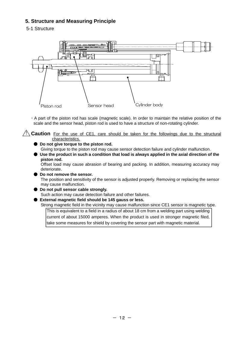
Piston rod Sensor head Cylinder body
5. Structure and Measuring Principle
5-1 Structure
・A part of the piston rod has scale (magnetic scale). In order to maintain the relative position of the
scale and the sensor head, piston rod is used to have a structure of non-rotating cylinder.
Caution For the use of CE1, care should be taken for the followings due to the structural
characteristics.
● Do not give torque to the piston rod.
Giving torque to the piston rod may cause sensor detection failure and cylinder malfunction.
● Use the product in such a condition that load is always applied in the axial direction of the
piston rod. Offset load may cause abrasion of bearing and packing. In addition, measuring accuracy may deteriorate.
● Do not remove the sensor.
The position and sensitivity of the sensor is adjusted properly. Removing or replacing the sensor may cause malfunction.
● Do not pull sensor cable strongly.
Such action may cause detection failure and other failures.
● External magnetic field should be 145 gauss or less.
Strong magnetic field in the vicinity may cause malfunction since CE1 sensor is magnetic type.
This is equivalent to a field in a radius of about 18 cm from a welding part using welding
current of about 15000 amperes. When the product is used in stronger magnetic filed,
take some measures for shield by covering the sensor part with magnetic material.
!
- 13 -
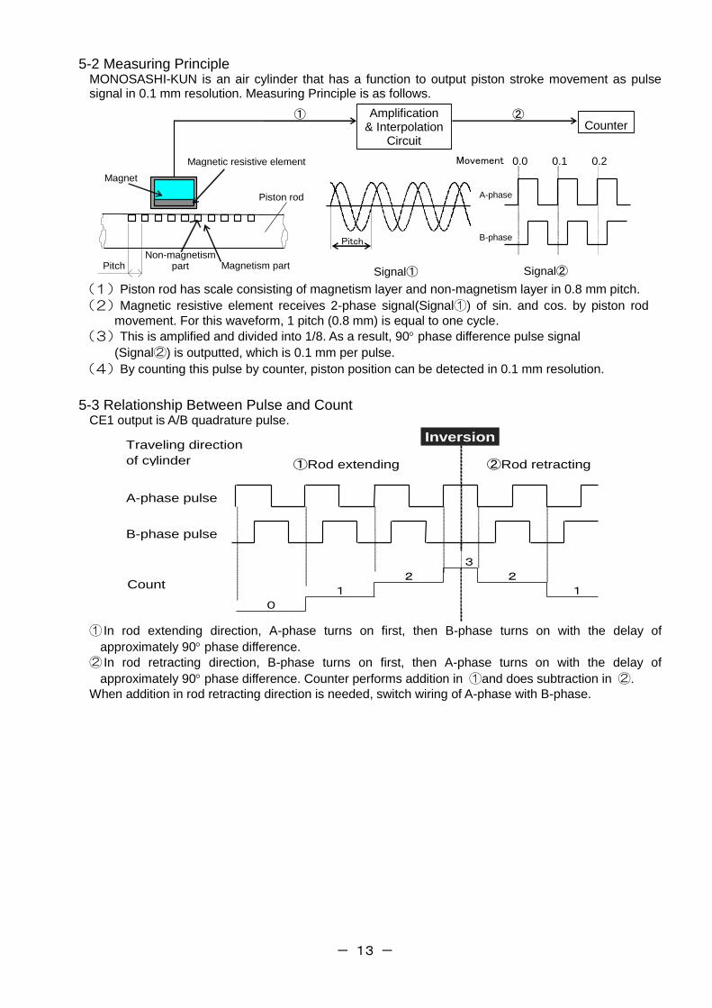
5-2 Measuring Principle MONOSASHI-KUN is an air cylinder that has a function to output piston stroke movement as pulse signal in 0.1 mm resolution. Measuring Principle is as follows.
Pitch Magnetism part Non-magnetism
part
Piston rod
Magnet
Magnetic resistive element
Amplification & Interpolation
Circuit
Counter ① ②
0.0 0.2 0.1
A-phase
B-phase
Movement
Signal① Signal②
Pitch
(1)Piston rod has scale consisting of magnetism layer and non-magnetism layer in 0.8 mm pitch.
(2)Magnetic resistive element receives 2-phase signal(Signal①) of sin. and cos. by piston rod
movement. For this waveform, 1 pitch (0.8 mm) is equal to one cycle.
(3)This is amplified and divided into 1/8. As a result, 90 phase difference pulse signal
(Signal②) is outputted, which is 0.1 mm per pulse.
(4)By counting this pulse by counter, piston position can be detected in 0.1 mm resolution.
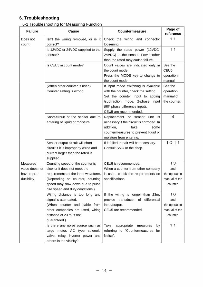
5-3 Relationship Between Pulse and Count CE1 output is A/B quadrature pulse.
A-phase pulse
B-phase pulse
Count 2
1
0
3
2
1
Inversion Traveling direction
of cylinder ①Rod extending ②Rod retracting
① In rod extending direction, A-phase turns on first, then B-phase turns on with the delay of
approximately 90 phase difference.
② In rod retracting direction, B-phase turns on first, then A-phase turns on with the delay of
approximately 90 phase difference. Counter performs addition in ①and does subtraction in ②.
When addition in rod retracting direction is needed, switch wiring of A-phase with B-phase.
- 14 -
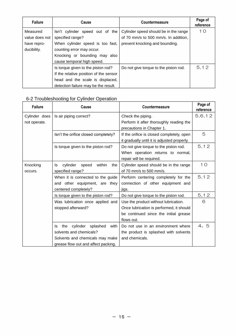
6. Troubleshooting
6-1 Troubleshooting for Measuring Function
Failure Cause Countermeasure Page of
reference
Does not
count.
Isn’t the wiring removed, or is it
correct?
Check the wiring and connector
loosening.
11
Is 12VDC or 24VDC supplied to the
sensor?
Supply the rated power (12VDC-
24VDC) to the sensor. Power other
than the rated may cause failure.
11
Is CEU5 in count mode? Count values are indicated only in
the count mode.
Press the MODE key to change to
the count mode.
See the
CEU5
operation
manual
(When other counter is used)
Counter setting is wrong.
If input mode switching is available
with the counter, check the setting.
Set the counter input to adding
/subtraction mode, 2-phase input
(90 phase difference input).
CEU5 are recommended.
See the
operation
manual of
the counter.
Short-circuit of the sensor due to
entering of liquid or moisture.
Replacement of sensor unit is
necessary if the circuit is corroded. In
addition, take some
countermeasures to prevent liquid or
moisture from entering.
4
Sensor output circuit will short-
circuit if it is improperly wired and
current larger than the rated is
supplied.
If it failed, repair will be necessary.
Consult SMC or the shop.
10,11
Measured
value does not
have repro-
ducibility
Counting speed of the counter is
slow or it does not meet the
requirements of the input waveform.
(Depending on counter, counting
speed may slow down due to pulse
rise speed and duty conditions.)
CEU5 is recommended.
When a counter from other company
is used, check the requirements on
specifications.
13
and
the operation
manual of the
counter.
Wiring distance is too long and
signal is attenuated.
(When counter and cable from
other companies are used, wiring
distance of 23 m is not
guaranteed.)
If the wiring is longer than 23m,
provide transducer of differential
input/output.
CEU5 are recommended.
10
and
the operation
manual of the
counter.
Is there any noise source such as
large motor, AC type solenoid
valve, relay, inverter power and
others in the vicinity?
Take appropriate measures by
referring to “Countermeasures for
Noise”.
11
- 15 -
Failure Cause Countermeasure Page of
reference
Measured
value does not
have repro-
ducibility.
Isn’t cylinder speed out of the
specified range?
When cylinder speed is too fast,
counting error may occur.
Knocking or bounding may also
cause temporal high speed.
Cylinder speed should be in the range
of 70 mm/s to 500 mm/s. In addition,
prevent knocking and bounding.
10
Is torque given to the piston rod?
If the relative position of the sensor
head and the scale is displaced,
detection failure may be the result.
Do not give torque to the piston rod. 5,12
6-2 Troubleshooting for Cylinder Operation
Failure Cause Countermeasure Page of
reference
Cylinder does
not operate.
Is air piping correct? Check the piping.
Perform it after thoroughly reading the
precautions in Chapter 1.
5,6,12
Isn’t the orifice closed completely? If the orifice is closed completely, open
it gradually until it is adjusted properly.
5
Is torque given to the piston rod? Do not give torque to the piston rod.
When operation returns to normal,
repair will be required.
5,12
Knocking
occurs.
Is cylinder speed within the
specified range?
Cylinder speed should be in the range
of 70 mm/s to 500 mm/s.
10
When it is connected to the guide
and other equipment, are they
centered completely?
Perform centering completely for the
connection of other equipment and
jigs.
5,12
Is torque given to the piston rod? Do not give torque to the piston rod. 5,12
Was lubrication once applied and
stopped afterward?
Use the product without lubrication.
Once lubrication is performed, it should
be continued since the initial grease
flows out.
6
Is the cylinder splashed with
solvents and chemicals?
Solvents and chemicals may make
grease flow out and affect packing.
Do not use in an environment where
the product is splashed with solvents
and chemicals.
4,5
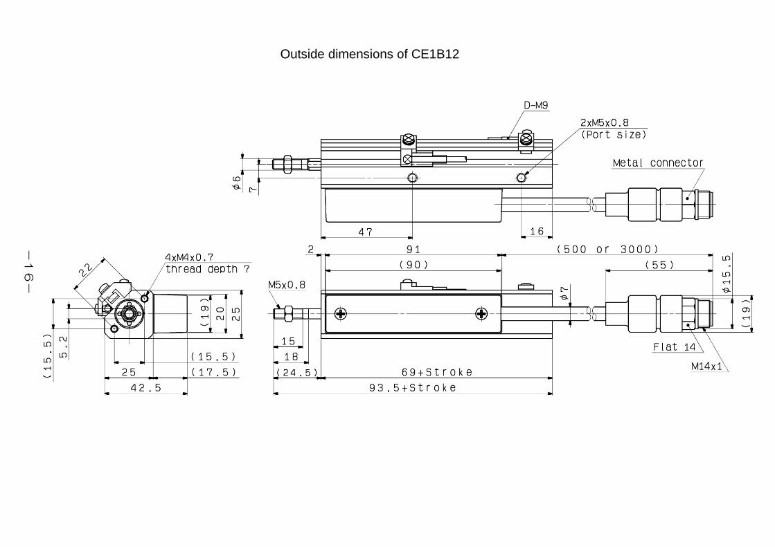
Outside dimensions of CE1B12
-16-
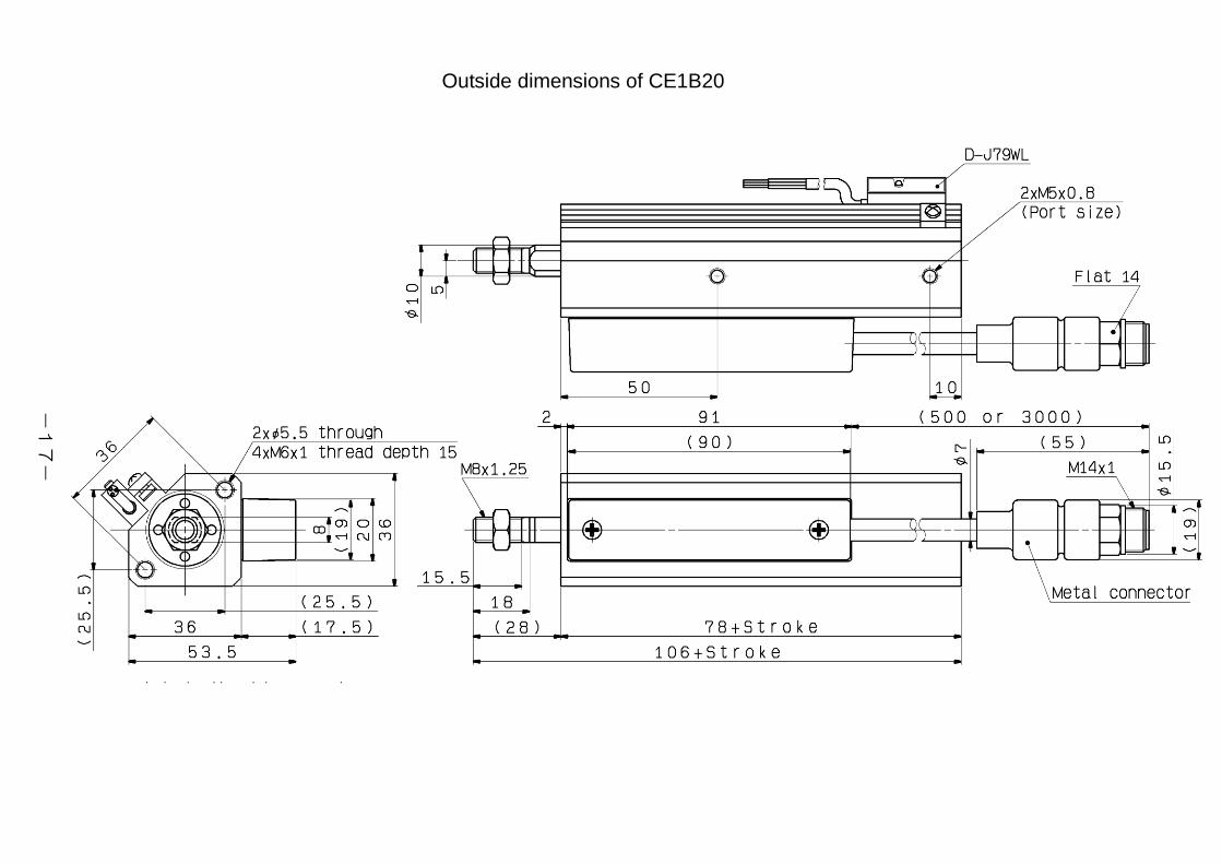
Outside dimensions of CE1B20
-17-
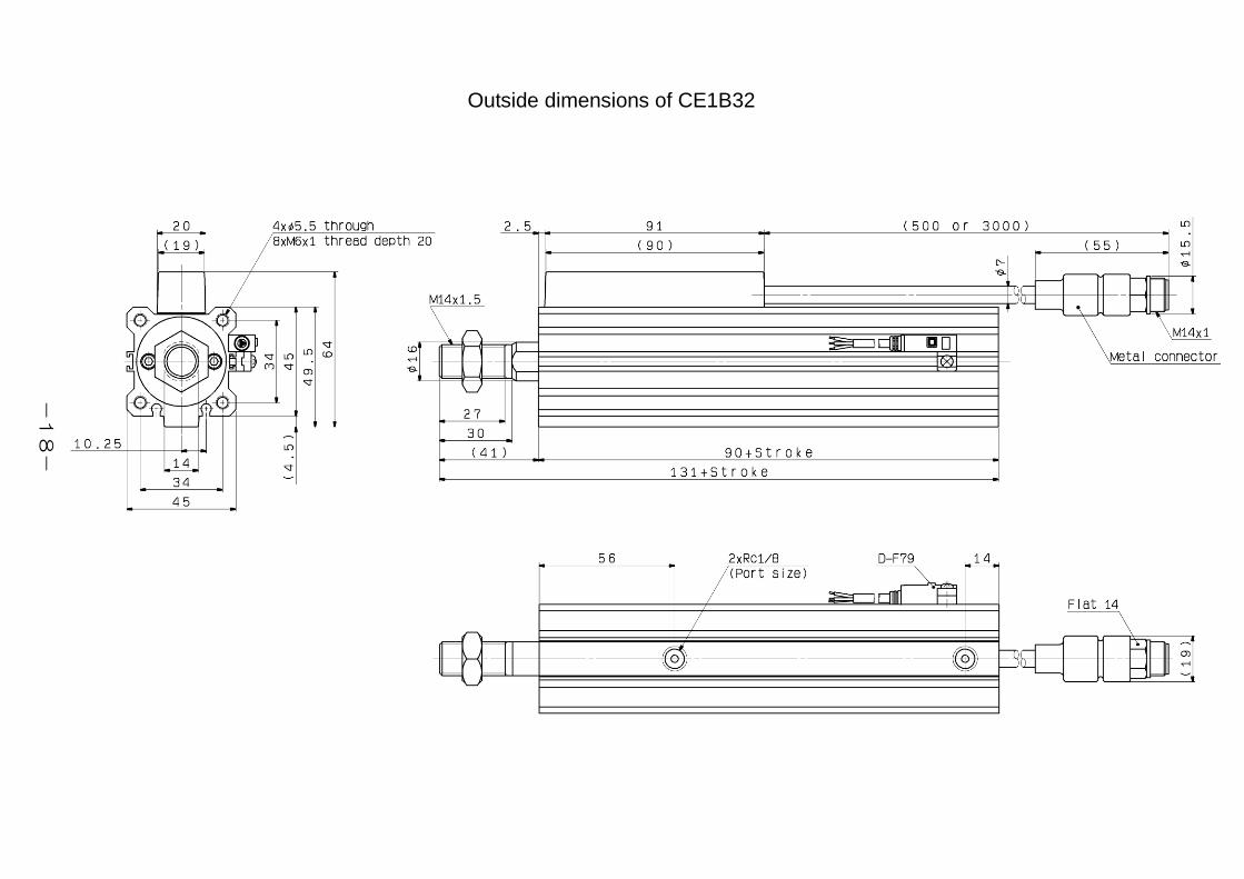
Outside dimensions of CE1B32
-18-
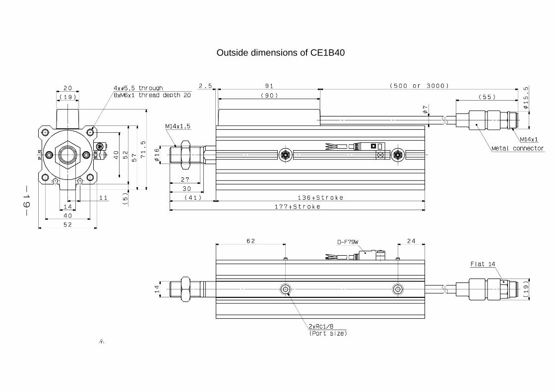
Outside dimensions of CE1B40
-19-

Outside dimensions of CE1B50
-20-
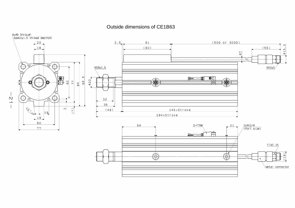
Outside dimensions of CE1B63
-21-
Revision history
4-14-1, Sotokanda, Chiyoda-ku, Tokyo 101-0021 JAPAN Tel: + 81 3 5207 8249 Fax: +81 3 5298 5362 URL http://www.smcworld.com Note: Specifications are subject to change without prior notice and any obligation on the part of the manufacturer. © 2011 SMC Corporation All Rights Reserved


