MonoScope: Automating Network Faults Diagnosis Based on Active Measurements Waiting W. T. Fok § , Xiapu Luo §‡ , Ricky Mok § , Weichao Li § , Yujing Liu ♮ , Edmond W. W. Chan † , and Rocky K. C. Chang § Department of Computing § School of Computer ♮ Noah’s Ark Lab † Shenzhen Research Institute ‡ National University of Huawei Technologies The Hong Kong Polytechnic University Defense Technology China {cswtfok|csxluo|cskpmok|csweicli|csrchang} China [email protected]@comp.polyu.edu.hk [email protected]Abstract—Network faults, such as router failures, cable out- ages, and configuration errors, could seriously affect network performance. In this paper, we use network faults very loosely, including those that will yield unfavorable end-to-end network performance, such as packet reordering and suboptimal routes. Diagnosing network faults on end-to-end paths is a very challeng- ing problem, because it generally involves other domains. Even if it can be done, the process is very time consuming, because multiple sources of data, which are scattered in different places, are needed for such diagnosis. In this paper, we consider the problem of making the fault diagnosis as automatic as possible. Based on coordinated active measurement from a set of end systems, we propose a procedure of detecting network faults and identifying their locations. Although this procedure cannot be fully automated for the time being, we show that some of the components could be automated, and we are automating them in a preliminary system called MonoScope. We demonstrate the efficacy of this procedure through several real-world cases that we have encountered in our four years of network monitoring experience. I. I NTRODUCTION Network failures or faults are not uncommon in the Internet and data center networks today [10], [14], [22]. They could be resulted from software and hardware bugs, misconfigurations, accidents, natural disasters, and even deliberate acts. In this paper, we use network faults very loosely, including those that will yield unfavorable end-to-end network performance, such as packet reordering and suboptimal routes. For example, a load balancer generates a high packet reordering rate, and an ISP discriminates a customer by assigning a suboptimal path to its routes, thus resulting in a poorer performance as compared with other “similar” customers. The possible impact of a network fault includes disruption in network connectivity and performance degradation. In the former, diagnosis can be performed based on routes [14]. In the latter the network connectivity may not be disrupted, but the end-to-end performance is affected. Since disruption in network connectivity also affects network performance, in this paper we consider fault diagnosis based on end-to-end path performance and route tracing. This diagnosis problem is very challenging, because it generally involves other domains. Even if it can be done, the process is very time consuming, because multiple sources of data, which are scattered in different places, are needed for such diagnosis. Nowadays only large-scale network faults leading to huge financial losses or blackout in major cities are reported in mass media. Most events remain out-of-sight while affecting end- system network services. The systems available for the edge to diagnose performance problems, such as Scriptroute [21], M- Lab [2], and Speedtest [3], restrict the diagnosis to some pre- selected remote servers. Therefore, they cannot be used for di- agnosing arbitrary paths. Individual installation of active mea- surement tools, such as perfSONAR [4] and HTTP/OneProbe [17], also does not help a user to effectively diagnose network faults for end-to-end paths. Based on our four years of experience on coordinated active measurement from a set of end systems, we propose in this paper a procedure of detecting network faults and identifying their locations. The key idea is to synchronize the end systems’ path measurement to the same remote destination, so that a network fault in these paths could be localized by detecting its impact on their path performance. The procedure thus consists of three consecutive steps. The first is to detect performance changes in individual paths. The detected changes will then be clustered in the time domain. Those path changes occurring in a small time window are suspected to come from the same network fault. In the last step, the routes for those paths identified in the second step will be analyzed to localize the fault. Although this procedure cannot be fully automated for the time being, we show in this paper that some of the components could be automated. Based on our preliminary system called MonoScope, the first two steps could be automated. But there are still a number of challenges to overcome to optimize their performance in terms of accuracy and detection time. However, due to the diversity of network faults, the last step will be extremely difficult to automate for a general-purpose system. This difficulty will be illustrated through the case of diagnosing a suboptimal path and a submarine cable fault. The main contribution of this paper is a three-step proce- dure to diagnose faults for end-to-end paths based on coordi- nated active measurement from a set of end systems (in §II). By analyzing each step, we also discuss the feasibility of au- tomating it in an operational system. We then demonstrate the efficacy of this procedure through several real-world cases that we have encountered in our four years of network monitoring experience (in §III). After discussing the related works in §IV,
Transcript
MonoScope: Automating Network Faults Diagnosis
Based on Active Measurements
Waiting W. T. Fok§, Xiapu Luo§‡, Ricky Mok§, Weichao Li§, Yujing Liu♮, Edmond W. W. Chan†,
and Rocky K. C. Chang§
Department of Computing§ School of Computer♮ Noah’s Ark Lab†
Shenzhen Research Institute‡ National University of Huawei Technologies
The Hong Kong Polytechnic University Defense Technology China
Abstract—Network faults, such as router failures, cable out-ages, and configuration errors, could seriously affect networkperformance. In this paper, we use network faults very loosely,including those that will yield unfavorable end-to-end networkperformance, such as packet reordering and suboptimal routes.Diagnosing network faults on end-to-end paths is a very challeng-ing problem, because it generally involves other domains. Evenif it can be done, the process is very time consuming, becausemultiple sources of data, which are scattered in different places,are needed for such diagnosis.
In this paper, we consider the problem of making thefault diagnosis as automatic as possible. Based on coordinatedactive measurement from a set of end systems, we proposea procedure of detecting network faults and identifying theirlocations. Although this procedure cannot be fully automated forthe time being, we show that some of the components could beautomated, and we are automating them in a preliminary systemcalled MonoScope. We demonstrate the efficacy of this procedurethrough several real-world cases that we have encountered in ourfour years of network monitoring experience.
I. INTRODUCTION
Network failures or faults are not uncommon in the Internetand data center networks today [10], [14], [22]. They could beresulted from software and hardware bugs, misconfigurations,accidents, natural disasters, and even deliberate acts. In thispaper, we use network faults very loosely, including those thatwill yield unfavorable end-to-end network performance, suchas packet reordering and suboptimal routes. For example, aload balancer generates a high packet reordering rate, and anISP discriminates a customer by assigning a suboptimal path toits routes, thus resulting in a poorer performance as comparedwith other “similar” customers.
The possible impact of a network fault includes disruptionin network connectivity and performance degradation. In theformer, diagnosis can be performed based on routes [14]. Inthe latter the network connectivity may not be disrupted, butthe end-to-end performance is affected. Since disruption innetwork connectivity also affects network performance, in thispaper we consider fault diagnosis based on end-to-end pathperformance and route tracing. This diagnosis problem is verychallenging, because it generally involves other domains. Evenif it can be done, the process is very time consuming, becausemultiple sources of data, which are scattered in differentplaces, are needed for such diagnosis.
Nowadays only large-scale network faults leading to hugefinancial losses or blackout in major cities are reported in massmedia. Most events remain out-of-sight while affecting end-system network services. The systems available for the edge todiagnose performance problems, such as Scriptroute [21], M-Lab [2], and Speedtest [3], restrict the diagnosis to some pre-selected remote servers. Therefore, they cannot be used for di-agnosing arbitrary paths. Individual installation of active mea-surement tools, such as perfSONAR [4] and HTTP/OneProbe[17], also does not help a user to effectively diagnose networkfaults for end-to-end paths.
Based on our four years of experience on coordinated activemeasurement from a set of end systems, we propose in thispaper a procedure of detecting network faults and identifyingtheir locations. The key idea is to synchronize the end systems’path measurement to the same remote destination, so that anetwork fault in these paths could be localized by detecting itsimpact on their path performance. The procedure thus consistsof three consecutive steps. The first is to detect performancechanges in individual paths. The detected changes will then beclustered in the time domain. Those path changes occurring ina small time window are suspected to come from the samenetwork fault. In the last step, the routes for those pathsidentified in the second step will be analyzed to localize thefault.
Although this procedure cannot be fully automated for thetime being, we show in this paper that some of the componentscould be automated. Based on our preliminary system calledMonoScope, the first two steps could be automated. But thereare still a number of challenges to overcome to optimize theirperformance in terms of accuracy and detection time. However,due to the diversity of network faults, the last step will beextremely difficult to automate for a general-purpose system.This difficulty will be illustrated through the case of diagnosinga suboptimal path and a submarine cable fault.
The main contribution of this paper is a three-step proce-dure to diagnose faults for end-to-end paths based on coordi-nated active measurement from a set of end systems (in §II).By analyzing each step, we also discuss the feasibility of au-tomating it in an operational system. We then demonstrate theefficacy of this procedure through several real-world cases thatwe have encountered in our four years of network monitoringexperience (in §III). After discussing the related works in §IV,
we conclude the paper in §V.
II. METHODOLOGY
A. The scope of network monitoring
We have been conducting network monitoring for the HongKong Academic and Research Network (HARNET) for overfour years. One of the most common activities is to diagnosenetwork performance problems revealed by the measurementresults. The HARNET connects mainly eight local universities,including our own university, through an optical ring, and alocal ISP (which is called HARNET ISP hereafter) providesthe Internet connectivity service. Besides connecting to HAR-NET, each university also subscribes additional service fromother ISP. Being an academic network, their primary concernis the performance of reaching other academic networks, suchas CERNET and Internet2.
As shown in Figure 1, the HARNET monitoring sys-tem consists of eight measurement systems, each deployedat each university. They are installed with HTTP/OneProbe(OneProbe@university) [17] and Tcptraceroute for measuringend-to-end network performance and tracing routes for over50 web servers in Hong Kong, Asia, Oceania, Europe, NorthAmerica, and Africa. The measurement results are connectedand analyzed by Planetopus [16], a network measurementmanagement system, and the results are then made available tothe HARNET users. The web servers are located at academicnetworks and commercial sites. The academic sites werechosen by the HARNET users, and others were added lateron to monitor network performance for specific regions, suchas Africa during the 2010 FIFA World Cup in South Africa.Therefore, the network paths under the monitoring cover awide geographical area and different types of networks.
Fig. 1. The HARNET monitoring system.
B. Data collection
We diagnose network faults based on the end-to-end pathperformance data and routes collected by us and other publiclyavailable network data, such as BGP routes. Moreover, anaccurate diagnosis occasionally needs information from newsfeeds, such as reports on submarine cable outages [8], [7].
1) Path performance: To facilitate the diagnosis, it ishighly desirable to obtain as much performance metrics aspossible. Since we cannot deploy measurement agents at the re-mote nodes of the network paths under monitoring, our systemis not able to obtain one-way network delay. However, we canobtain other metrics for one-way paths using HTTP/OneProbe[17] which dispatches a sequence of back-to-back packet pairsfor measurement:
1) ROUND-TRIP TIME (RTT) Each probe consisting of twodata TCP packets carrying an HTTP request will inducea response that consists of one or two TCP data packetscarrying a (partial) HTTP response from the web server.The RTT is therefore measured by the arrival time ofresponse packet subtracted by the departure time of thecorresponding probe packet. Moreover, we use only thefirst packet’s RTT, because the second packet’s RTT maybe biased by the first packet. We take the median fromaround 100 observations for a time-series analysis.
2) PACKET LOSS RATE We obtain forward-path and reverse-path loss rates based on the HTTP/OneProbe measure-ment. The response packets contain information for de-termining whether any of the packets in the probe andresponse is lost. We compute a packet loss rate for eachdirection by dividing the number of probes that suffer lossby the total number of probes.
3) END-TO-END PACKET REORDERING RATE We obtainforward-path and reverse-path packet reordering ratesbased on the HTTP/OneProbe measurement. The responsepackets contain information for determining whether thepacket pairs in the probe are reordered or that in theresponse are reordered if two packets can be induced fromthe server. We compute a packet reordering rate for eachdirection by dividing the number of probes that experiencereordering by the total number of probes.
2) Coordinated traceroutes: Our measurement systemsalso perform regular traceroutes for the forward paths. How-ever, unlike other traceroute measurement, our system per-forms coordinated traceroute where the eight measurementsystems perform traceroute to the same destination at the sametime. The individual traceroutes, after resolving the IP aliasesfor routers, are fused into a single traceroute diagram as illus-trated in Figure 2 where the eight measurement systems (UA-UH) trace the paths to a web server in www.jp.apan.net.
Moreover, previous works, such as [18], show that IPaddress, BGP prefix, and RTT can be used to determine thegeographic location of the hops. They are especially useful forpopular ASes, and we use the information to identify commonforward paths in the next section. We also characterize routechange from the continuous traceroute data obtained for eachpath using Jaccard distance [7].
3) BGP data for reverse-path diagnosis: Public sources,such as [5] and [6], offer BGP data for analysis. The BGP in-formation for the measurement systems’ ASes shows possiblereverse paths. Moreover, BGP updates can be used to studythe impact of network disruption events [11].
C. A fault diagnosis procedure
1) Coordinated measurement: The major mechanism thatfacilitates effective fault diagnosis is to conduct the path per-
UE UH
UF
UA UB UG
Asia Pacific Advanced Network - Japan
(AS7660)
HARNET
UDUC
apanjp-RGE.hkix
.ne t
ns . jp .apan.net
2 .39 ms 2 .51 ms
HARNET
51 .82 ms 51 .71 ms
UA
1 .18 ms 0 .84 ms
UB
0 .71 ms 1 .09 ms
UC
0 .54 ms 1 .01 ms
UD
1 .35 ms 1 .07 ms
UE
1 .01 ms 1 .01 ms
UF
53 .00 ms 52 .89 ms
UG
0 .37 ms 1 .05 ms
UH
1 .78 ms 0 .96 ms
Fig. 2. A combined traceroute from the eight measurement systems to a webserver in www.jp.apan.net.
formance and traceroutes in a coordinated manner, so that thesemeasurements could be correlated for localizing the faults.Figure 3 depicts two scenarios of coordinated measurement.In Figure 3(a), each measurement node measures the pathsto multiple destinations around the same time. Thus, if theperformance of all the path deteriorates around the same time,the fault location should be at the segments close to themeasurement node. In Figure 3(b), all measurement nodesmeasure the paths to a given destination around the same time.Thus, if the performance of the network segments close tothe destination deteriorates, the performance degradation willshow up in all the paths.
(a) A measurement node mea-sures paths to multiple destina-tions at the same time.
(b) Multiple measurement nodesmeasure paths to the same desti-nation at the same time.
Fig. 3. Two scenarios of coordinated network measurement.
Our monitoring system setup follows Figure 3(b), becausethere is generally route diversity for the paths from the eightmeasurement nodes to a given destination. This route diversitycould be used to diagnose problems at the destination networkand at some common hops between the two ends of a path.At the same time, problems at HARNET and HARNET ISPcan be diagnosed by path measurement launched by severalmeasurement nodes at the same time. The measurement nodesare therefore time synchronized, and they are scheduled tomeasure the paths to the same web server around the sametime.
2) A three-step procedure: Based on the measurement re-sults obtained from the coordinated measurement, we proposethree major steps to detecting and locating network faults:
1) CHANGE-POINT DETECTION The first step is to detectchange points in the time series of network path perfor-mance under monitoring. The change points may revealthe onset of performance degradation through one or more
performance metrics. Besides, the forward-path routes arealso analyzed for changes. This step therefore is appliedto each network path independently.
2) CHANGE-POINT CORRELATION This step is to identify asimilar change in multiple paths. If a change is detectedfor only a single path, we cannot possibly locate the fault.However, if a change is observed in multiple paths aroundthe same time, these paths will be further analyzed in thenext step for fault localization. The step therefore willprovide such set of candidate paths, whenever identified,to the next step.
3) FAULT LOCALIZATION Given the set of candidate pathsfrom the last step and corresponding traceroutes, this steptries to localize the faults. If the change detected in step1 indicates a forward-path fault (e.g., a high forward-path loss rate), the common hops appearing in the setof forward paths are the candidate locations. However, ifthe network fault occurs on the reverse path, an AS-pathanalysis will be performed to identify the fault locations.
a) Change-point detection: Detecting changes in atime-series of RTT, packet loss rate, or packet reordering ratecould be framed as a change-point detection problem whichdiscovers time points at which properties of time-series datachange. This problem is also known as anomaly detectionand event detection. The change-point detection problem hasbeen studied extensively for different types of problems, suchas fraud detection in cellular systems and intrusion detectionin computer networks. Common approaches to this probleminclude Sequential Probability Ratio Test, Cumulative Sum,and Exponentially Weighted Moving Average.
For detecting changes in forward-path routes, we quantifythe degree of forward-route change using the Jaccard distanceof AS-path and IP-path as we have done in [7]. In thetime series of Jaccard distance values, a spike represents asignificant route change. To analyze the reverse-path changes,we use the publicly available BGP data. The number of BGPupdates for a specific AS can be used to quantify the routingdynamics of the network. Similar to the traceroute analysis,a spike in the time series represents a significant reverse-pathroute change of the AS.
b) Change-point correlation: This step attempts tocluster the changes detected on different paths from the firststep. The rationale is that a network fault can induce perfor-mance changes on multiple paths if they traverse the locationof the network fault. Therefore, we set a time window to collectchanges occurred within the window and identify them to bethe result of the same network fault. This set of candidatepaths will be passed to the next step for fault localization. Inour measurement setting, we use a window of 20 minutes forchange-point clustering, because each path is measured everyten minutes, and 20 minutes is enough for obtaining at leastone measurement.
c) Fault localization: This last step is to localize thenetwork fault that induces performance change as preciseas possible based on the set of candidate paths identifiedfrom the second step and the coordinated traceroute results.If there is only a single fault1, it could be located on the
1The multiple-fault case is much more challenging, and it is not consideredin this paper.
forward path or reverse path. To diagnose a forward-pathfault, we use the coordinated traceroute results to identify thehops/nodes that are common to the set of candidate paths. Ifsuch hops/nodes exist, the network fault is very likely locatedon them. Otherwise, it is possible that the fault is on thereverse path. Diagnosing a reverse-path fault is much morechallenging, because performing reverse traceroute is still adaunting task even when a reverse traceroute facility [13] isavailable. Instead, we use the AS paths obtained from publicBGP data. Similar to the coordinated traceroute, we obtain theASes that are common on the candidate paths.
The network faults detected in our four-year experiencewith HARNET monitoring are commonly found in HARNETISP and critical links in Internet, such as submarine cables.Moreover, we have detected network faults on the web server’sside and CDN services, such as YouTube. In the next section,we will illustrate the three-step procedure using three realnetwork faults discovered by the HARNET monitoring.
D. What can be automated?
In our current HARNET monitoring system, we haveautomated the path performance measurement and traceroute,but have not automated the fault diagnosis process. For thethree-step procedure, our preliminary experience shows thatthe first two steps can be automated. However, the challengeis to decrease the false positives and false negatives, and todecrease the detection delay. Moreover, there are two types oftime-series data: RTT, and the packet loss and reordering rates.In our experience, the bursty nature of the loss and reorderingevents makes it more challenging to detect them.
The third step will be the most difficult to automate. As willbe illustrated in the next section, identifying a submarine cablefault requires manual analysis of the performance time-seriesand traceroutes, and ground truth about the submarine cablelayout and the traffic going through them. This observation,however, is not surprising, because our network monitoringsystem is not designed specifically for monitoring submarinecables.
III. THREE REAL-WORLD CASES
We present in this section three cases where path perfor-mance degradation was observed and analyzed according tothe methodology proposed in §II. In §III-A, we diagnose anISP-scale packet reordering problem, which was introducedby a per-packet load balancer on a downstream link. In §III-B,the HARNET ISP performed reverse-path traffic engineeringthat affected some, but not all, universities’ path performance.In §III-C, our system captured a network fault caused byJapan’s earthquake in 2011 which damaged five submarinecables landed at Japan. It is important to note that the IP routeswere unchanged in all three cases. Therefore, route analysisbased on IP and BGP cannot diagnose these problems.
A. Anomalous reverse-path reordering rate
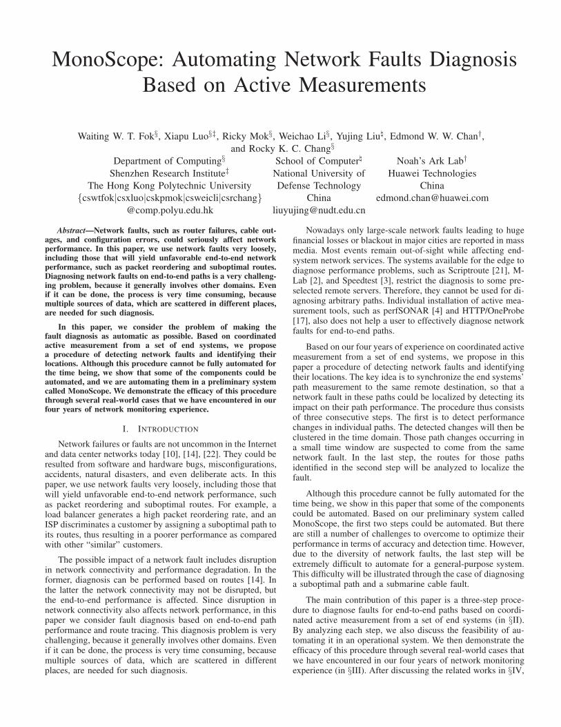
Step 1 - Change-point detection: The reverse-pathpacket reordering rate (RVR) of all paths were negligible on orbefore 17 October 2010. On 18 and 24 October, however, twoRVR bursts that lasted for less than two days were found inthe UF-Citibank path (where Citibank is a web server). For the
UF-Citibank path and some other paths, the diurnal patternsof high RVR became permanent since 29 October. The RVRreached as much as 45%.
Figure 4(a) shows the average RVR for the UF-Citibankpath in October and November 2010. We plot the mean RVRusing raw data and four aggregation levels. As expected, ahigher aggregation will yield a smoother curve, thus facili-tating a more accurate detection for changes. However, thedownside is a longer detection time. The standard deviationof the average rates in Figure 4(b) further shows that the 2-hour aggregation is sufficient for smoothing the RVR. Aftersmoothing the RVR, it is not difficult to see that the changein the RVR could be detected automatically by a time-seriesanomaly detection algorithm.
1/2-day Stat from Raw Data - Std Dev1-day Stat from 1/2-hour Average - Std Dev
2-day Stat from 1-hour Average - Std Dev4-day Stat from 2-hour Average - Std Dev8-day Stat from 4-hour Average - Std Dev
(b) The standard deviation.
Fig. 4. Time series for the average and standard deviation of reverse-pathreordering rates for the UF-Citibank path.
Step 2 - Change-point correlation: The surges in RVRwere found not only in the UF-Citibank path, but also inthe paths from other measurement nodes to 17 overseasdestinations. As an example, Figure 5 shows the four-weekRVR time series around 30 Oct 2010 for the 17 affected pathsoriginated from UF and the paths from all eight measurementnodes (UA to UH) to NISSAN, another web server selected forpath measurement. The RVR surges for these 25 paths occurredaround the same time. Therefore, a window of reasonable sizewill be able to automatically cluster them together for furtheranalysis in the next step.
Step 3 - Fault localization: Figure 6 illustrates thenetwork connections of HARNET. We have obtained this infor-mation from an authoritative source and have also confirmedit by our traceroute. As shown, HARNET is peered withoverseas academic and research networks, and connects tolocal networks via the Hong Kong Internet eXchange (HKIX).
10-17 10-27 11-06
UG-nissan
UD-nissan
UE-nissan
UH-nissan
UA-nissan
UC-nissan
UF-nissan
UB-nissan
0
5
10
15
20
25
RVR(%)
(a) Paths from the eight measurement nodes to NISSAN.
Fig. 5. Heat-map diagram of reverse-path reordering between 17 October2010 and 13 November 2010.
Moreover, HARNET provides connectivity to other overseasnetwork through the HARNET ISP.
Since we have the ground truth about the IP addressesof each router in HARNET, we can easily map IP pathsto actual paths within HARNET. Packets routed through aspecific router reflect the default forwarding path in use toother networks. We note that the paths that do not sufferfrom the high RVR problem all went through the links toHKIX and overseas academic and research networks (i.e., thedotted lines). On the other hand, the rest that were affectedwent through the link to HARNET ISP, and their common IPhops are within HARNET ISP. Therefore, the network faultresponsible for the high RVR must be located at the linkbetween HARNET and HARNET ISP or within HARNET ISP.
Fig. 6. A high-level view of HARNET’s connectivity.
Impact of our diagnosis: We reported our finding tothe HARNET users, and the information was subsequentlypassed to the operators in HARNET ISP who admitted that thehigh RVR rates were possibly generated by a per-packet load-balancing function at a router on the link between HARNETand HARNET ISP. On 13 May 2012, as promised by HARNETISP, the router was replaced, and the RVR returned to normalever since.
B. Poor latency performance from ISP’s traffic engineering
Step 1 - Change-point detection: On 24 January 2011,we observed a 70 ms increase of RTT from two measurementnodes UA and UD to Citibank’s in the US (www.citibank.com). Figure 7 shows the RTT, forward-path loss rate (FWL)
and reverse-path loss rate (RVL) for the UA-Citibank path inJan 2011. The RTT before 24 January was stable but wasincreased sharply after that. This abrupt increase could beeasily picked up by an abrupt change detection algorithm.
100
150
200
250
01/01 08/01 15/01 22/01 29/01-10
0
10
RT
T(m
s)
Lo
ss(%
)
UA->www.citibank.com
RTT FW(+)/RV(-) loss
Fig. 7. RTT and loss rates of the UA-Citibank path in January 2011.
Step 2 - Change-point correlation: This step is tocorrelate the RTT surges found in the UA-Citibank and UD-Citibank paths with other change points detected from otherpaths. Figures 8(a) and 8(b) show the RTT of the paths fromall eight measurement nodes to Citibank, and the paths fromUA to the 17 overseas destinations. In Figure 8(a), besides the70 ms increase for the UA-Citibank and UD-Citibank paths,other paths experienced only 20 ms increase in their RTTs.Moreover, Figure 8(b) shows the RTTs for the paths from UAto the 17 destinations. However, no change points from non-UA paths coincide with the change point in the UA path.
01-01 01-11 01-21 01-31
UG-citibank
UD-citibank
UE-citibank
UH-citibank
UA-citibank
UC-citibank
UF-citibank
UB-citibank
180
200
220
240
260
280
300
RTT(ms)
(a) The paths from the eight measurement nodes to Citibank.RTT of Measurements from UA
01-01 01-11 01-21 01-31
UA-subway_de
UA-telstra_nz
UA-hsbc_de
UA-NYTimes
UA-lenovo
UA-bbc
UA-citibank
UA-ausnews
UA-nla
UA-auspost
UA-fujitsu
UA-nissan
UA-tomita
UA-cpan
UA-nokia
UA-eng4
UA-eng3
UA-eng2
0
100
200
300
400
500
600
700
RTT(ms)
(b) The path from UA to overseas destinations.
Fig. 8. A heat-map diagram of RTT in January 2011.
Step 3 - Fault localization: Since the two change pointsfound for the UA-Citibank and UD-Citibank paths are not clus-tered with others, we investigate the underlying network faultby collecting information concerning the remote destination.We first quantify the change in the IP forward paths by theJaccard distance of the traceroute results. Figure 9 shows theresult for the UA-Citibank path. The Jaccard distance for theAS path is zero, therefore not shown here. Similar patternswere found for all eight paths from the measurement nodes toCitibank. Since the Jaccard distance is small around 24 January2011, we rule out that the forward route change is responsiblefor the RTT surge.
We used undns [20] to resolve the geolocation of the hopsobtained by traceroute. The forward path is denoted as FR inFigure 10. Except for five low-latency subpaths in the local
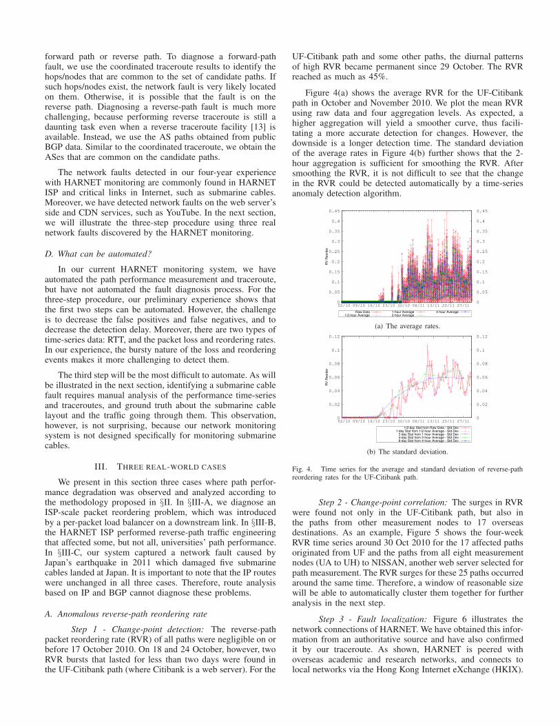
Fig. 9. Jaccard distance of the UA-Citibank IP-path from 10/1/2011 to6/2/2011.
NEWTT network (AS9381) which is HARNET ISP, all theeight AS paths are the same.
From [1], we found that the destination network CITI-GROUP (AS32287) has two major upstream providers, AT&T(AS7018) and LEVEL3 (AS3356). We then collected reverse-path information through looking glasses (LG) of both ASes.A single LG at AT&T (AS7018) provides traceroute function.We used the function to identify a common reverse AS-pathRR1 for all eight universities.
On the other hand, the BGP routes collected from LEVEL3(AS3356) show interesting results. First of all, in severalLEVEL3’s LGs, the route to CITIGROUP (AS32287) directlywent through LEVEL3’s facilities in Dallas (ipcolo1.Dallas1).The two ASes seemed to be connected at the site. UsingLEVEL3’s LG in Dallas, two sets of AS paths labeled by RR2
& RR3 for the eight local universities were identified. RR2
was assigned to UA and UD, and RR3 to other universities.
We then performed traceroute at the LEVEL3’s LG. Weused undns again to infer the hops’ geolocations. The under-lying physical paths of RR2 and RR3, as shown in Figure10, went through very different geographic regions. WhileRR3 passed through a trans-Pacific link (US West-coast-Japan-HK), RR1 and RR2 traversed a trans-Atlantic link (US East-coast-Europe) and an Eurasia link (Europe-Southeast Asia-HK). RR2 was longer than RR3 in terms of geographicaldistance, thus the propagation delay also.
CitigroupLEVEL3
AT&T
NEWTT
SEABONE-NETFR
Hong Kong
FR
Hong Kong
FRUnresolved
FR
Dallas
RR2/RR3
Dallas
Dallas
Washington
RR2
C&W
Paris
RR2
TMNet
MalaysiaRR2
Los Angeles
RR3
Pacnet
Japan
RR3
RR1/RR2
RR3
RR1RR1
Fig. 10. Forward and reverse routes between UA-UH and Citibank.
Our path measurement matches LEVEL3’s reverse pathsRR2 and RR3 but not AT&T’s RR1. It is because if the UA-Citibank and UD-Citibank paths went through the longer RR2,the RTT difference of 60 ms is reasonable. If all round-trippaths went through FR and RR1, then the RTT differencecannot be explained.
Impact of our diagnosis: We reported our findingsto the HARNET users, and they were then forwarded to
HARNET ISP. At around 2:00am (HKT) of 23 July 2011,a few hours after the UA user filed a complaint to HARNETISP, the RTTs for the UA and UD paths decreased significantlyfrom 300 ms to 200 ms. A subsequent lookup at LEVEL3’sDallas LG revealed that RR3 was assigned to all eight localuniversities.
C. Performance degradation due to submarine cable damage
Step 1 - Change-point detection: On 11 March 2011,a 9.0-magnitude earthquake occurred near Japan. Numerousaftershocks were recorded days after the main earthquakes.From the UA’s path measurement, the reverse-path loss raterose up to 5% in ten overseas paths for a five-day periodimmediately after the earthquake. A change of RTT patterncan also be found on 11 March for the UA-nla path. The RTTsurged from 320 ms to 420 ms and was much more fluctuatedthan before. Figure 11 shows a heat map diagram, depictingthe RTT and reverse loss rate for 10 out of 19 overseas pathsmeasured from UA. The y-axis shows, from top to bottom,the measured paths to 3 hosts in Europe, 5 hosts in the US,1 host in Australia, and 2 hosts in Japan. The time that 9.0earthquake occurred is marked with a vertical arrow. Theseincreases in RVL and RTT could be detected by a changedetection algorithm.
Main Earthquake
9/3 11/3 13/3 15/3
UA-fujitsuUA-tomita
UA-nlaUA-citibankUA-NYTimes
UA-cpanUA-eng2
UA-subway_deUA-bbcUA-eng3
50
100
150
200
250
300
350
400
450
RTT(ms)
(a) RTT.
Main Earthquake
9/3 11/3 13/3 15/3
UA-fujitsuUA-tomita
UA-nlaUA-citibankUA-NYTimes
UA-cpanUA-eng2
UA-subway_deUA-bbcUA-eng3
0
5
10
15
20
25
30
35
RVL(%)
(b) Reverse-path loss rate.
Fig. 11. A heat-map diagram of RTT and reverse-path loss rate from 09March 2011 to 16 March 2011 for ten paths originated from UA.
Step 2 - Change-point correlation: The performancedegradation detected in step 1 could be grouped into fiveclusters. They were in the form of bursts in RVL lasting forless than a day, once in each of the five consecutive daysimmediately after the earthquake. The first cluster on 11 Marchcontained 5 paths, and four subsequent clusters from 12 Marchto 15 March include additional five paths, thus a total of 10paths. These ten paths that observed the RVL surges wereclustered together to diagnose the underlying network fault.
Step 3 - Fault localization: Tracerouting the ten pathsshowed that the traffic were forwarded to five different carriersafter leaving HARNET ISP, and the destination hosts werelocated in ten different ASes. But around 40 paths to HongKong or overseas destinations did not observe the high RVL.Therefore, it is not caused by a network fault in the localnetwork, HARNET ISP, or remote networks. Due to the scaleof affected paths in different destination, the “discriminative”performance experienced by the universities in the last case isnot exhibited here.
To diagnose this network fault with impact on a largerregion, we first find the possible geolocation of the paths ac-cording to the available submarine cable systems. The rationalefor this approach is that submarine cable systems are now themajor media for carrying inter-continental data traffic. Figure12 illustrates a simplified version of the global submarinecables systems. To make it simple, we intentionally miss outcables connecting islands, such as Iceland, Greenland, andPapua New Guinea. We have observed that the cable systemsare highly redundant and concentrated in coastal cities ofdeveloped areas, such as North America, Europe, and Asia.For example, network traffic between Asia and Europe can gothrough either:
1) The submarine cables running between Asia and Africathrough Middle East, and Mediterranean cables to Europe;
2) The transpacific cables between Asia (Japan inclusive ornot) and the North America, continental cable networksthrough West and East coast of the North America, andtransatlantic cables to Europe;
3) Same as above but through Australia before reaching theNorth America.
AsiaEurope
Australia
Africa
North
America
South
America
Europe
AfricaAfrica
JP
Fig. 12. A simplified map of worldwide submarine cables.
We then shortlist possible geographic paths by comparingend-to-end RTT with the estimated delay of each geographicpath. The propagation delay component of an RTT path servesthe baseline of the RTT. On top of that other componentsinclude processing delays in network devices and end hosts,and queueing delays in routers during peak hours.
The actual geographical path and the length of the subma-rine cable links are not public information. We can thereforeonly estimate the shortest path and minimum latency. Insteadof conducting a full study on network delay of the Internet, wepropose a workaround. We first estimate the intra-region delaysas the propagation delays of the most direct path, includingland and submarine cables, of the two far-most points withina region. We inflate the end-to-end geographical delay by asum of the intra-region delay of intermediate regions on thepath and half of the delays in source and destination regions.
Table I summarizes the minimum RTTs of inter-regionallinks (white) and possible intra-regional links (grey). If no linkis available between two regions, the cell is blacked out. Forexample, the RTT of the UA-BBC path is 220 ms. For theaforementioned three possible paths running between Asia andEurope, their estimated RTTs are:
Therefore, the first path is likely the actual geographicalpath for the UA-BBC path.
TABLE I. MINIMUM RTTS (IN MS) OF INTER-REGIONAL LINKS
(WHITE) AND AVERAGE RTTS (IN MS) OF INTRA-REGIONAL LINKS
(GREY).
Region EU Afr Asia JP Aus NA SA
EU 60 90 200 65
Afr 150 200 65
Asia 60 45 65 150
JP 20 90 90
Aus 40 130
NA 60 65
SA 150
Finally, we infer which regional paths were the originof the performance degradation by analyzing the shortlistedgeographic paths of the ten paths identified in step 2. TableII presents the shortlisted geographic paths that carry thetraffic sourced from Hong Kong and ended at remote networkslocated in Japan, Australia, Europe, and the US. Each possiblepath is numbered in an ascending order of the number oflinks used, e.g., path(2) for HK-Europe consisting of twolinks: Asia-N.America and N.America-Europe. Although wecannot conclude which regional links were affected, the linksthat were used by more than two affected paths are goodcandidates. They include Asia-Japan, Japan-N.America, andAsia-N.America.
TABLE II. POSSIBLE GEOGRAPHIC PATHS BETWEEN NODES IN HONG
KONG AND OVERSEAS NETWORKS.
Links Japan Australia Europe US
Asia-Japan ♦1 ♦24 ♦3 ♦2
Japan-N.America × ♦4 ♦3 ♦2
Asia-Australia × ♦1 × ×
Japan-Australia × ♦2 × ×
Asia-N.America × ♦3 ♦2 ♦1
Australia-N.America × ♦34 × ×
Asia-Africa × × ♦1 ×
Africa-Europe × × ♦1 ×
N.America-Europe × × ♦23 ×
♦ = Link possibly used by at least one path,
× = None used the link
Impact of our diagnosis: Besides the analysis in step3, we have also analyzed BGP data from RIPE [5] andRouteViews [6]. We have observed that among the pathsfrom 128 different ASes to UA’s network, 31.54% of thempassed through FLAG (AS15412). It was a crucial providerfor transmitting data traffic from the Internet to UA. Afterthe earthquake, at 12:00 am on 11 March 2011, the RIB ofRouteViews showed that there was a sharp increase in thenumber of AS paths going through FLAG. About 22,000 ASpaths were re-routed to FLAG for transiting the traffic to otherusers. We can infer that this BGP rerouting behavior worsenedthe congestion of FLAG. The UA paths passing through FLAGwere therefore expected to experience high packet loss andlong queueing delays.
IV. RELATED WORK
Turner et al. [22] reported the statistics about the failureevents in a large regional network consisting of over 200routers. Their results show that the causes include from hard-ware, software, power, configuration, and so on. They alsoincluded the impact of the causes among which software andpower have a higher impact. In this paper, our measurement
covers submarine cable outages which are not covered in [22].Moreover, we consider a broader meaning of network faults,including ISP’s network configurations that cause very highpacket reordering rates and suboptimal routes.
Another related problem is to detect network outages inthe Internet. Both Qian et al. [19] and the Hubble system[12] use a similar approach of actively sending probes to theIPv4 address space. Their objective is to determine how manyaddresses are unreachable due to outages and cluster themto events. The objective of our system, on the other hand,is to detect and localize network faults that will affect the pathperformance which generally will not deteriorate to the pointof unreachable. Therefore, the network faults considered in thispaper cannot be detected by the methods in [19] and [12].
Detecting and avoiding route failures is another frequentlyaddressed problem in the literature, e.g., [19], [12], [23], [9],[14]. In particular, Zhang et al. [23] diagnosed routing disrup-tions associated with any large networks using a collaborativeprobing launched from end systems. Our three-step procedureis in fact similar to theirs on the block level, and coordinatedtraceroute (called collaborated traceroute) is also used for theirdiagnosis. However, our goal is to diagnose network faultsresponsible for performance degradation, and route disruptionis just one of the possible causes for performance change.
Instead of launching active probing, some systems relyon passive analysis to detect network faults. However, suchsystems usually require much information that is not accessibleto end users. The system proposed by Kompella et al. requiresSNMP data along with the information about Shared Risk LinkGroups and their relationships [15]. Based on log informationincluding configuration files, syslog messages, administratornotices, and BGP data, Turner et al. investigate the causes andthe impact of network faults in the CENIC network [22].
V. CONCLUSIONS
In this paper, we proposed a three-step procedure to diag-nose network faults, which encompass all types of anomalies,based on coordinated active path measurement. We have de-vised the three steps based on our experience on fault diagnosisin HARNET. The first step, where change points are detected,could be automated with existing change-detection algorithms.Step 2 could also be made automatic by clustering the change-points detected on multiple paths using a moving time window.However, the most complicated analysis for fault localizationin step 3 cannot be automated easily. As illustrated in the threecase studies, step 3 could involve analyzing reverse paths basedon traceroute and BGP routes, and RTT of inter-regional links.We are currently in the process of automating the first two stepsin our preliminary system called MonoScope.
ACKNOWLEDGEMENTS
This work is partially supported by grants (ref. no. H-ZD91, H-ZL17) from the Joint Universities Computer Centreof Hong Kong, and a grant (ref. no. G-YK26) from The HongKong Polytechnic University and a Tier-2 project (ref. no.GHP/027/11) from the Innovation Technology Fund in HongKong. We also thank the reviewers for their careful reading ofthe manuscript and comments.
REFERENCES
[1] The CAIDA AS Relationships Dataset, 2011-01-16. http://www.caida.org/data/active/as-relationships/.
[6] University of Oregon RouteViews project. http://www.routeviews.org/.
[7] E. Chan, X. Luo, R. Chang, W. Fok, and W. Li. Non-cooperativediagnosis of submarine cable faults. In Proc. PAM, 2011.
[8] R. Chang, E. Chan, W. Li, W. Fok, and X. Luo. Could ash cloud ordeep-sea current overwhelm the Internet? In Proc. USENIX HotDep,2010.
[9] N. Feamster, D. Andersen, H. Balakrishnan, and F. Kaashoek. Measur-ing the effects of Internet path faults on reactive routing. In Proc. ACM
SIGMETRICS, 2003.
[10] P. Gill, N. Jain, and N. Nagappan. Understanding network failures indata centers: measurement, analysis, and implications. In Proc. ACM
SIGCOMM, pages 350–361, 2011.
[11] Y. Huang, N. Feamster, A. Lakhina, and J. Xu. Diagnosing networkdisruptions with network-wide analysis. In Proc. ACM SIGMETRICS,2007.
[12] E. Katz-Bassett, H. Madhyastha, J. John, A. Krishnamurthy, D. Wether-all, and T. Anderson. Studying black holes in the Internet with Hubble.In Proc. NSDI, 2008.
[13] E. Katz-Bassett, H. V. Madhyastha, V. K. Adhikari, C. Scott, J. Sherry,P. Van Wesep, T. Anderson, and A. Krishnamurthy. Reverse traceroute.In Proc. USENIX NSDI, 2010.
[14] E. Katz-Bassett, C. Scott, D. Choffnes, I. Cunha, V. Valancius, N. Feam-ster, H. Madhyastha, T. Anderson, and A. Krishnamurthy. LIFE-GUARD: Practical repair of persistent route failures. In Proc. ACM
SIGCOMM, 2012.
[15] R. Kompella, J. Yates, A. Greenberg, and A. Snoeren. IP faultlocalization via risk modeling. In Proc. USENIX NSDI, 2005.
[16] W. Li, W. Fok, E. Chan, X. Luo, and R. Chang. Planetopus: A systemfor facilitating collaborative network monitoring. In Proc. IFIP/IEEE
[17] X. Luo, E. Chan, and R. Chang. Design and implementation of TCPdata probes for reliable and metric-rich network path monitoring. InProc. USENIX ATC, 2009.
[18] V. Padmanabhan and L. Subramanian. An investigation of geographicmapping techniques for Internet hosts. In Proc. ACM SIGCOMM,volume 31, pages 173–185, 2001.
[19] L. Quan, J. Heidemann, and Y. Pradkin. Detecting Internet outageswith precise active probing. Technical Report ISI-TR-2012-678b,USC/Information Sciences Institute, 2012.
[20] N. Spring, R. Mahajan, and D. Wetherall. Measuring isp topologies withrocketfuel. In Proc. ACM SIGCOMM, pages 133–145. ACM, 2002.
[21] N. Spring, D. Wetherall, and T. Anderson. Scriptroute: a public Internetmeasurement facility. In Proc. USITS, 2003.
[22] D. Turner, K. Levchenko, A. Snoeren, and S. Savage. California faultlines: understanding the causes and impact of network failures. In Proc.
ACM SIGCOMM, 2010.
[23] Y. Zhang, Z. Mao, and M. Zhang. Effective diagnosis of routingdisruptions from end systems. In Proc. USENIX NSDI, 2008.