32
1 Montageanleitung Assembly instruction Deckensystem Ceiling System

1
MontageanleitungAssembly instruction
DeckensystemCeiling System

2 3
Inhalt Seite1 Lasttabelle.......................................................... 52 Montage ............................................................ 62.1 Deckenschiene montieren.................................. 62.2 Starre Schiebebühne montieren......................... 82.3 Schrägstellbare Schiebebühne montieren.......... 102.4 Doppelschiebebühne montieren..................... 122.5 Fahrantrieb montieren........................................ 143 Zubehör.............................................................. 163.1 Stromband......................................................... 163.1.1 Aufhängeabstände............................................. 153.1.2 Montage Aufhänger............................................ 183.1.3 Mechanische und elektrische Verbindung.......... 193.1.4 Stromabnehmerwagen montieren...................... 213.1.5 Elektrischer Anschluß......................................... 223.2 Motorendeckenteleskop..................................... 243.2.1 Montage Motorendeckenteleskop...................... 253.2.2 Fernbedienung................................................... 263.3 Generatorkörbe................................................... 27 3.3.1 Montage Generatorkörbe.................................... 283.3 Scherengitter....................................................... 293.3.1 Montage Scherengitter........................................ 303.4 Weiteres Zubehörprogramm............................... 31

2 3
Content Page1 Table of loads.................................................... 52 Assembly............................................................ 62.2 Assembling the ceiling rails................................ 62.2 Assembling the rigid travelling stage.................. 82.3 Assembling the rotatable travelling stage........... 102.4 Assembling the double travelling stage........... 122.5 Assembling the motor drive................................. 143 Accessories......................................................... 163.1 Electric cable...................................................... 163.1.1 Standard spacing between the hangers............. 173.1.2 Assembling the suspensions.............................. 183.1.3 Mech. and electric coupling of bus-way tracks... 193.1.4 Assembling the power pick up trolley................. 213.1.5 Electrical connection.......................................... 223.2 Motor-ceiling telescope....................................... 243.2.1 Assembling the motor-ceiling telescope............. 253.2.2 Remote control................................................... 263.3 Generator boxes................................................. 273.3.1 Assembling the generator boxes........................ 283.4 Pantograph......................................................... 293.3.1 Assembling the pantograph................................ 303.5 Further accessorie program................................ 31

4 5

4 5
1 Lasttabelle / Table of Loads
Stützweite L m 2 2,5 3 3,5 4 4,5 5 5,5 6 7 8
Punktlast F max. N 5620 4500 3160 2330 1710 1410 1140 940 790 580 440
Streckenlast q max. N/m 5620 2910 1690 1060 710 500 360 274 210 130 90
Durchbiegung f mm 10 12,5 15 17,5 20 22,5 25 27,5 30 35 40
Span l m 2 2,5 3 3,5 4 4,5 5 5,5 6 7 8
Lumped load F max. N 5620 4500 3160 2330 1710 1410 1140 940 790 580 440
Line load q max. N/m 5620 2910 1690 1060 710 500 360 274 210 130 90
Deflection f mm 10 12,5 15 17,5 20 22,5 25 27,5 30 35 40
Position und Abstand der Deckenschienen festlegen. Anzahl und Abstand der Sicherheitsaufhängbügel TE 2071 gemäß Lasttabelle oder Planungsunterlagen festlegen.Je nach Material der vorhandenen Decke geeignete Befestigungsele-mente auswählen. Wir empfehlen eine Tragfähigkeit von 1500 N( = 150 kg ) pro Befestigungseinheit.
Determine the position and distance of the ceiling rails. Determine the number of the safety suspension mounting bracket TE 2071 in according to the load chart or plans.Select the fastening elements to suit the ceiling material. We recom-mend a standard carrying capacity of 1500 N ( = 150 kg ) per point of fastening.

6 7
2 Montage / Assembly2.1 Deckenschienen montieren / Assembling the Ceiling rails
● Sicherheitsaufhängbügel andübeln und Deckenschienen, montieren. (1) Toleranz: Höhe und seitlich +/- 1mm/lfdm. ● In eines der zu verbindenden Profilenden die 4 Nutsteine in die oberen und unteren Nutkanäle rechts und links einschieben. Zentrierstifte einsetzen und Profile zusammenfügen. (2) ● Anschläge an beiden Schienenenden montieren. (3)
● Peg on the safety suspension mounting bracket and ceiling rails. Attach the profile. (1) Tolerance: Height and laterally +/- 1mm/running metre.● Push in the 4 sliding blocks into the upper and lower lateral grooves on the left and right sides. (2) Insert the centering pins and join the profiles.● Attach end stop and buffers on each end of the rail. (3)
1
3
1
1
1
1
22
1
3
33

6 7
1
2
3
TE 2071
TE 2010
TE 2119-2
8 9
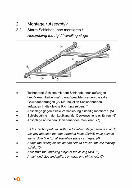
2 Montage / Assembly2.2 Starre Schiebebühne montieren / Assembling the rigid travelling stage
● Technoprofil Schiene mit dem Schiebebühnenlaufwagen bestücken. Hierbei muß darauf geachtet werden dass die Gewindebohrungen (2x M6) bei allen Schiebebühnen- aufwagen in die gleiche Richtung zeigen. (4)● Anschläge gegen axiale Verschiebung einseitig montieren. (5)● Schiebebühne in den Laufkanal der Deckenschiene einführen. (6)● Anschläge an beiden Schienenenden montieren. (7)
● Fit the Technoprofil rail with the travelling stage carriages. To do this pay attention that the threaded holes (2xM6) must point in same direction for all travelling stage carriages. (4)● Attach the sliding blocks on one side to prevent the rail moving axially. (5)● Assemble the travelling stage at the ceiling rails. (6)● Attach end stop and buffers on each end of the rail. (7)
5
6
44
44
6
77
77
5

8 9
4
6
7
5
TE 2160-2
TE 2080

10 11
2 Montage / Assembly2.3 Schrägstellbare Schiebebühne montieren / Assembling the rotatable travelling stage
8
10
11
8
11
119
9
11
● Technoprofil Schiene mit den Schiebebühnenlaufwagen bestücken. Hierbei muß darauf geachtet werden dass die Gewindebohrungen (2x M6) bei allen Schiebebühnenlaufwagen in die gleiche Richtung zeigen. (8)
● Anschläge gegen Verschiebung und Herauslaufen montieren. (9)● Schiebebühne in den Laufkanal der Deckenschiene einführen.(10)● Anschläge an beiden Schienenenden montieren. (11)
● Fit the Technoprofil with the travelling stage carriages. To do this pay attention that the threaded holes (2xM6) must point in same direction for all travelling stage carriages. (8)
● Attach the Sliding blocks on both side to prevent the rail moving out and to adjust the axially. (9)
● Assemble the travelling stage at the ceiling rails. (10)● Attach end stop and buffers on each end of the rail. (11)

10 11
8
11
10
Durch die inneren Anschläge wird die axiale verschiebung der Schiebebühne eingestellt.By the inner sliding blocks adjust the axially moving of the travelling stage can.
TE 2170-2
TE 2119-29

12 13
2 Montage / Assembly2.4 Doppelschiebebühne montieren / Assembling the double travelling stage
14
13
121213
15
15
1515
14
● Technoprofil Schiene mit den Schiebebühnenlaufwagen bestücken. Hierbei muß darauf geachtet werden dass die Gewindebohrungen (2x M6) bei allen Schiebebühnenlaufwagen in die gleiche Richtung zeigen. (12)● Anschläge gegen axiale Verschiebung einseitig montieren. (13)● Schiebebühne in den Laufkanal der Deckenschiene einführen. (14)● Anschläge an beiden Schienenenden montieren. (15)
● Fit the Technoprofil with the travelling stage carriages. To do this pay attention that the threaded holes (2xM6) must point in same direction for all travelling stage carriages. (12)● Attach the Sliding blocks on one side to prevent the rail moving axially. (13)● Assemble the travelling stage at the ceiling rails. (14)● Attach end stop and buffers on each end of the rail. (15)

12 13
15
12
14
TE 2180-2
TE 208013
14 15
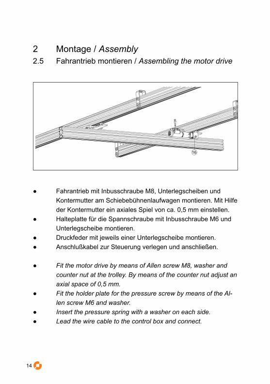
2 Montage / Assembly2.5 Fahrantrieb montieren / Assembling the motor drive
● Fahrantrieb mit Inbusschraube M8, Unterlegscheiben und Kontermutter am Schiebebühnenlaufwagen montieren. Mit Hilfe der Kontermutter ein axiales Spiel von ca. 0,5 mm einstellen.
● Halteplatte für die Spannschraube mit Inbusschraube M6 und Unterlegscheibe montieren.
● Druckfeder mit jeweils einer Unterlegscheibe montieren.● Anschlußkabel zur Steuerung verlegen und anschließen.
● Fit the motor drive by means of Allen screw M8, washer and counter nut at the trolley. By means of the counter nut adjust an axial space of 0,5 mm.
● Fit the holder plate for the pressure screw by means of the Al-len screw M6 and washer.
● Insert the pressure spring with a washer on each side.● Lead the wire cable to the control box and connect.
16
14 15
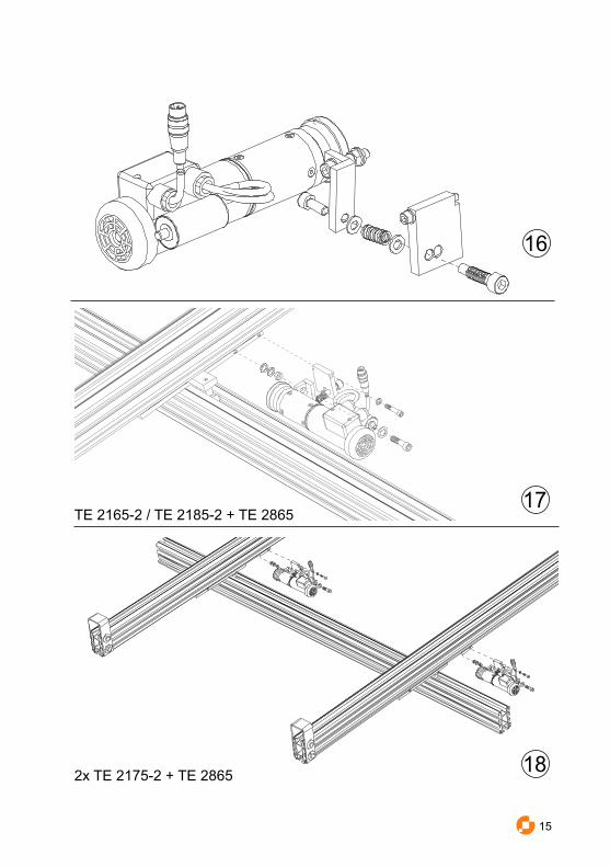
16
17
182x TE 2175-2 + TE 2865
TE 2165-2 / TE 2185-2 + TE 2865

16 17
3 Zubehör / Accessories3.1 Kunststoff-Stromband / Electric cable
19
19 Gleitaufhänger20 Festpunktaufhänger21 Verbindungsmuffe 22 Endkappe23 Stromabnehmerwagen24 Elektrischer Anschluß
19 Sliding Suspension20 Fixed Point Suspension21 Joint plaint 22 End cap23 Power pic up trolley24 Electrical Connection
20
21
22
23
24

16 17
3.1.1 Aufhängeabstände / Standard spacing between the hangers
● Das Kunststoff-Stromband wird mit dem Festpunktaufhänger TE 4016 starr an einem Ende der Deckenschiene ange-schraubt. (20) Die restlichen Aufhänger sind Gleitaufhänger. Die beiden äußeren Aufhänger sind von rechts und links jeweils ca. 0,75 m auf die Normstücke zu schieben. Der Aufhängeabstand beträgt im Normalfall 1,50 m.
● Fit the plastic electric cable with the fixed point Suspension at one end of the ceiling rail. Assemble the both outer suspensions about 0.75 metres from each end. The Standard spacing of these hangers is 1.50 metres.
750 1500 750
TE 4010 TE 4016
TE 4012TE 4018
TE 4018
TE 4060

18 19
3 Zubehör / Accessories3.1.2 Montage der Aufhänger / Assembling the Suspensions
TE 4018TE 4016
● Stromschiene mit Aufhänger und Montagewinkel im mittleren äußeren Nutkanal montieren. Der Festpunktaufhänger kann
nicht vormontiert werden. Bei der Montage auf das Stromband- teilstück sind die Ausprägungen an der Unterseite des Fest- punktaufhängers in die angebrachten Bandausnehmungen (ca. 0,75 m vom Ende des Teilstückes) einzuhängen. Die Gleit- aufhänger sind entsprechend der Bauanleitung vorzumontieren. ● Fit the plastic electric cable with the angel and support bracket
in the medium lateral groove on the outside of the ceiling rail by means of a sliding block and screw. When suspension TE 4016 is beeing fitted to the respective bus-way track, the ears at its lower ends are to be hooked into the recesses in the plastic electric cable (at about 0.75 metres from each track‘s ends). Preassemble sliding suspension TE 4018 according to specifications.

18 19
3.1.3 Mechanische und elektrische Verbindung / Mechanical and electric coupling of bus-way tracks
● Die elektrische Verbindung der Teilstücke erfolgt mit Verbindungsmuffen (21). Bevor Sie die Teilstücke miteinander verbinden, prüfen Sie nochmals, ob sich die gelb/grün ausgelegten Rillen an den Teilstücken einheitlich auf einer Seite befinden. Anschlußbänder elektrisch und mechanisch mit Verbindungsmuffe verbinden.
● Bus-way tracks are electrically connected by means of screwed-on connecting bars (21). Prior to joining bus-way tracks, make sure yellow and green inlaid grooves on the track are all on the same side. Joint plate, for mechanical and electric joining of the plastic electric cables.
21 TE 4010

20 21
3.1.3 Mechanische und elektrische Verbindung / Mechanical and electric coupling of bus-way tracks
● Zur elektrischen Isolation und zum mechanischen Schutz wird die Stoßstelle mit einem Isolierbandzuschnitt überklebt. Dabei ist zu beachten, daß das Isolierband oberhalb der Bandausnehmungen angesetzt wird. Bei der Montage der Verbindungsmuffen zur mechanischen Verbindung der Teilstücke ist darauf zu achten, dass die Ausprägungen an der Unterseite der Halbschalen in die angebrachten Bandausnehmungen eingehängt werden
● For electric insulation and mechanical protection, track joints are covered with an appropriate length of friction tape. Make sure that the tape does not block recesses in the plastic electric cable. When fitting the joint plates for mechanical coupling of plastic electric cables, take care that ears on the lower side of the halfshells are hooked into the bus-way recesses.
TE 4010

20 21
3.1.4 Stromabnehmerwagen montieren / Assembling the power pick up trolley
● Die Sicherheitsrippen am Stromabnehmerwagen TE 4060 verhindern ein falsches Einsetzen.
● Der Wagen wird richtig eingesetzt, wenn die gelb/grün ausgelegten Längsrillen auf der gleichen Seite sind wie die gelb/grün ausgelegten Rillen im Stromband-Gehäuse.
● Das Anschlußschema ist im Verteilerkasten angegeben. ● Safety ribs on power pick up trolley TE 4060 (23) make it
impossible to insert them the wrong way. ● The trolley collector will be properly put in, when its yellow and
green inlaid nerves are on the same side with the yellow and green inlaid grooves on the bus-way shell.
● For connection diagram look inside distribution box.
Vorsicht! Vor dem Öffnen, Schiene von der Stromzufuhr trennen!Caution! Disconnect power supply before opening the cover!
TE 4060

22 23
3.1.5 Elektrischer Anschluss / Electrical connection
23
● Der elektrische Anschluss der Anlage erfolgt mit Anschlussklemmen (23) gemäß Zeichnung.
● Endeinspeisung mechanisch mit Verbindungsmuffe verbinden. ● Zur elektrischen Isolation und zum mechanischen Schutz
wird die Stoßstelle mit einem Isolierbandzuschnitt überklebt. Dabei ist zu beachten, daß das Isolierband oberhalb der Bandausnehmungen angesetzt wird.
● Bei der Montage der Verbindungsmuffen zur mechanischen Verbindung der Teilstücke ist darauf zu achten, dass die Ausprägungen an der Unterseite der Halbschalen in die angebrachten Bandausnehmungen eingehängt werden
● Bus-way tracks are electrically connected by means of screwed-on connectors (23) according to the drawing.
● Joint plate for mechanical joining of the plastic electric cables.● For electric insulation and mechanical protection, track joints
are covered with an appropriate length of friction tape. ● Make sure that the tape does not block recesses in the plastic
electric cable. When fitting the joint plates for mechanical coupling of plastic electric cables, take care that ears on the lower side of the halfshells are hooked into the bus-way
Vorsicht! Vor dem Öffnen, Schiene von der Stromzufuhr trennen!Caution! Disconnect power supply before opening the cover!

22 23
24
L1
N
L2 L3
23
TE 4012
TE 4012

24 25
3 Zubehör / Accessories3.2 Motorendeckenteleskop / Motor-ceiling telescope
25
26
26
27
30
2829
TE 2525 3125 Kabelfernbedienung26 Fanggurt 27 Fangseil28 Flügelschraube29 Aufnahme für Lampenadapter30 Entriegelung für Lampenadapter31 Lampendadapter TE 2525
25 Cable remote control 26 Safety belt27 Safety cable28 Wing screw29 Lampadapter30 Unlocking device for the lampadapter31 Lampadapter TE 2525

24 25
3.2.1 Montage Motorendeckenteleskop / Assembling the motor-ceiling telescope
33
● Friktionsbremse mit Feder und Kunsstoffstift in die in die 6 Kant - Hülsen stecken (32) ● Motorendeckenteleskop in den Laufkanal der Schiebebühne einführen ● Anschläge an beiden Schienenenden montieren (33)
● Assemble the friction brake with spring and plastic pin (32)● Assemble the Motor-ceiling telescope at the travelling stage ● Attach end stop and buffers on each end of the rail (33)
32
26 27
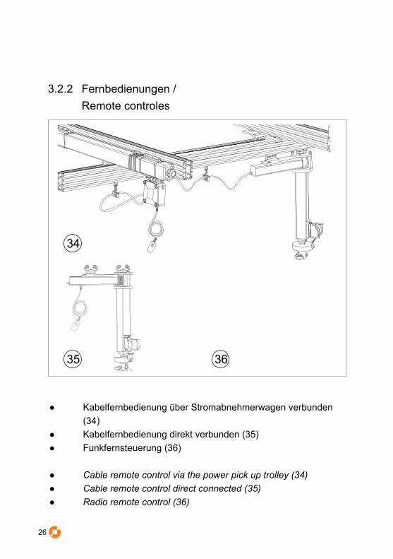
3.2.2 Fernbedienungen / Remote controles
● Kabelfernbedienung über Stromabnehmerwagen verbunden (34)● Kabelfernbedienung direkt verbunden (35)● Funkfernsteuerung (36)
● Cable remote control via the power pick up trolley (34)● Cable remote control direct connected (35)● Radio remote control (36)
34
35 36

26 27
3 Zubehör / Accessories3.3 Generatorkörbe / Generator boxes
39
38
37 Universal Sicherheits-Aufhängebügel TE 2071 38 Teleskopabhängung TE 2606 / TE 260739 Generatorkorb entsprechend dem Fabrikat 40 Verstellschraube zum Abhängen in 10 cm Schritten
37 Universal safety suspension bracket TE 207138 Telescopic suspension TE 2606 / 260739 Generator box according to the brand 40 Adjusting screw to change the lenght in 10 cm steps
37TE 2071
TE 2606 / 110 - 190 cmTE 2607 / 210 - 390 cm
40

28 29
3.3.1 Montage Generatorkörbe / Assembling the generator boxes
● Sicherheitsbügel an der Teleskopabhängung mit Unterleg- scheiben, einer Kronenmutter und einem Splint montieren● Teleskopabhänung am Generatorkorb mit Unterlegscheibe und Schraube montieren● Teleskopabhängung mit Generatorkorb und 4 Nutsteinen am Profil des Laufwagens montieren
● Assemble the safety suspension bracket at the telescopic suspension with washers, castle nut and splint● Assemble the telescopic suspension at the generator box with washer and screw● Assemble the telescopic suspension with generator box and 4 sliding blocks at the travelling stage

28 29
3 Zubehör / Accessories3.4 Scherengitter / Pantograph
4341
44
42
45
Um die Tragkraft zu Erhöhen können zwei Ferdern angebraht werden.
Use two springs to increase the lifting capacity.
41 Fangseil42 Flügelschraube43 Aufnahme für Lampenadapter44 Entriegelung für Lampenadapter45 Schraube zum Einstellen der Feder 41 Safety cable42 Wing screw43 Lampadapter44 Safety pin to unlock45 Screw to adjust the spring

30 31
3.4.1 Montage Scherengitter / Assembling the pantograph
47
46
● Friktionsbremse mit Feder und Kunsstoffstift in die in die 6 Kant - Hülsen stecken (46) ● Scherengitter in den Laufkanal der Schiebebühne einführen ● Anschläge an beiden Schienenenden montieren (47)
● Assemble the friction brake with spring and plastic pin (32)● Assemble the pantograph at the travelling stage ● Attach end stop and buffers on each end of the rail (33)

30 31
3.5 Weiteres Zubehörprogramm / Further accessorie program
● TE 2114: Minirolle, Kugelgelagert bis 100 N Tragkraft● TE 2115: Kabelträger 3 fach, zum Einhängen in die Minirolle ● TE - : Federzug ● TE - : Federzug● TE 2155: Lastrolle mit vertikaler Bohrung 10mm bis 750 N T Tragkraft
● TE 2114: Mini-runner, 100 N carrying capacity ● TE 2115: Cable Carrier, Triple, to hook into the mini-runner● TE : Spring balancer● TE : Spring balancer● TE 2155: Load runner with vertical 10 mm drill hole and 750 N carrying capacity
TE ----TE ---- TE 2115 TE 2155TE 2114

32
© Studio- Service Bacht GmbH 2006. All Rights Reserved.
Weitergabe sowie Vervielfältigung, Verbreitung und/oder Bearbeitung dieser Dokumentation, Verwertung und Mitteilung seines Inhalts sind verboten, soweit nicht ausdrücklich gestattet. Zuwiderhandlungen verpflichten zu Schadenersatz. Alle Rechte für den Fall der Patenterteilung, Gebrauchsmuster- oder Geschmacksmustereintragung vor-behalten. Alle Warenzeichen und eingetragene Warenzeichen sind Eigentum der jeweiligen Inhaber. Die Wiedergabe von Gebrauchsnamen, Handelsnamen, Warenbezeichnungen usw. in dieser Dokumentation berechtigt auch ohne beson-dere Kennzeichnung nicht zu der Annahme, dass solche Namen im Sinne der Warenzeichen- und Markenschutz- Gesetzgebung als frei zu betrachten wären und daher von jedermann benutzt werden dürfen.
Circulation and reproduction, dissemination and/or editing of this documentation as well as sale and notification of its contents are prohibited unless explicitly allowed. Contraventions shall oblige the offending party to pay compensation. We reserve all rights in the event of the awarding of patents and registration of industrial designs or taste designs. All trademarks and registered trademarks are the property of the respective owner. The reproduction of industrial names, trade names, goods designations etc. in this documentation does not provide entitlement even without special identification to assume that such names for the purposes of trademark and copyright legislation were to be considered to be free and therefore useable by anyone.
Studio-Service Bacht GmbHLiebigstraße 26D-45145 Essen
Fon +49.201.730097Fax [email protected]
2006-June-21 V. 1.0


