455 Monte Carlo simulation of the LANSCE target/moderator/reflector/shield geometry H. G. Hughes, III Group X-6, MS B226 Los Alamos National Laboratory Los Alamos, NM 87545 ABSTRACT: We present a detailed computer model of the existing LANSCE Target/Moderator/Reflector/Shield system. We describe the HETC/MCNP Monte Carlo code system used with this model, and we introduce a calculation designed to make comparisons with experimental results. Introduction The Target/Moderator/Reflector/Shield’ (TMRS) system of the Los Alamos Neutron Scattering Center2 (LANSCE) has been extensively described in the meetings and Proceedings of the International Collaboration on Advanced Neu- tron Sources. This paper presents a detailed computer simulation of the TMRS geometry and describes Monte Carlo particle transport calculations using this simulation. The purpose of this investigation is twofold: we wish to compare calculated fluxes in the flight paths to experimental measurements; and we wish to have available a standard Monte Carlo model both for parameter stud- ies of the existing LANSCE facility, and for accurate studies of possible future modifications and upgrades.3 The HETUMCNP Code System at Los Alamos Our computational tool for these calculations is the HETC Code System,4 the Los Alamos version of a computer program for the transport of nucleons, pions, and muons, based on the high-energy Monte Carlo code HETC,5 origi- nally developed at Oak Ridge National Laboratory (ORNL). The HETC code uses the Monte Carlo intranuclear cascade model of Bertini and the evapora- tion model of Dresner to describe the physics of nuclear interactions. Parti- cles are transported between interactions through material and void regions in space, as defined with three-dimensional general geometry, with charged parti- cles losing energy according to the continuous-slowing-down model. In the Los Alamos version, the geometric transport capability is that of the continuous energy neutron/photon Monte Carlo code MCNP.6 HETC currently includes as user options two models for fission induced by high-energy interactions: the ORNL model by Alsmiller and others,7 and the Rutherford Appelton Labora- tory (RAL) model by Atchison.”
Transcript
455
Monte Carlo simulation of the LANSCE target/moderator/reflector/shield geometry
H. G. Hughes, III Group X-6, MS B226 Los Alamos National Laboratory Los Alamos, NM 87545
ABSTRACT: We present a detailed computer model of the existing LANSCE Target/Moderator/Reflector/Shield system. We describe the HETC/MCNP Monte Carlo code system used with this model, and we introduce a calculation designed to make comparisons with
experimental results.
Introduction
The Target/Moderator/Reflector/Shield’ (TMRS) system of the Los Alamos
Neutron Scattering Center2 (LANSCE) has been extensively described in the meetings and Proceedings of the International Collaboration on Advanced Neu-
tron Sources. This paper presents a detailed computer simulation of the TMRS geometry and describes Monte Carlo particle transport calculations using this simulation. The purpose of this investigation is twofold: we wish to compare calculated fluxes in the flight paths to experimental measurements; and we wish to have available a standard Monte Carlo model both for parameter stud- ies of the existing LANSCE facility, and for accurate studies of possible future modifications and upgrades.3
The HETUMCNP Code System at Los Alamos
Our computational tool for these calculations is the HETC Code System,4 the Los Alamos version of a computer program for the transport of nucleons,
pions, and muons, based on the high-energy Monte Carlo code HETC,5 origi- nally developed at Oak Ridge National Laboratory (ORNL). The HETC code
uses the Monte Carlo intranuclear cascade model of Bertini and the evapora-
tion model of Dresner to describe the physics of nuclear interactions. Parti- cles are transported between interactions through material and void regions in space, as defined with three-dimensional general geometry, with charged parti- cles losing energy according to the continuous-slowing-down model. In the Los Alamos version, the geometric transport capability is that of the continuous energy neutron/photon Monte Carlo code MCNP.6 HETC currently includes as user options two models for fission induced by high-energy interactions: the ORNL model by Alsmiller and others,7 and the Rutherford Appelton Labora- tory (RAL) model by Atchison.”
--‘\a.
456 Simulation of targeWmoderator/ref/ector/shield
The philosophy of the HETC code is to treat all interactions by protons, pions, and muons within HETC, but to treat neutron interactions only above a cutoff energy, typically 20 MeV at Los Alamos. Any neutron emerging from a reaction with energy below the cutoff has its kinematic parameters recorded on a neutron file for subsequent transport by a Monte Carlo code utilizing ENDF/B-based neutron cross-section libraries. At Los Alamos, a version of MCNP modified to accept the neutron file as an input source is used to complete the particle transport; at other installations, the MORSE code is often used.
Calculational results from the MCNP phase of the computation can be obtained directly from the standard MCNP tallies, and a number of modified output edits appropriate to accelerator problems have been provided. In addition, both HETC and MCNP can write history files containing a (nearly) complete description of events occurring during the computations. Edited tallies of the initial HETC run, the subsequent MCNP run, or both runs in combination are obtained by using the HTAPE code to process data recorded on the history files. The edit options available with HTAPE include surface current and flux, cell- averaged neutron flux, particle production spectra, residual mass production and mean excitation, energy deposition by cell or material, mass-energy balance by cell or material, pulse shape analysis of surface current, gas production by cell or material, and global emission spectrum recorded in polar and azimuthal bins.
The MCNP phase of the computation can be executed as a coupled neu- tron/photon problem; however, obtaining a photon source from the high-energy interactions computed by HETC requires executing the PHT code. PHT ac- cepts the history file as input and produces a gamma file containing a photon source for MCNP in the same format as the neutron file. In the current ver- sion, the gamma source arises from two processes: 1) decay of neutral pions produced in the intranuclear cascade and 2) de-excitation of residual nuclei after particle evaporation.
The neutron file and the gamma file can be merged to serve as a source for MCNP in a coupled neutron/photon problem that describes the transport of the entire gamma-ray source in the system. Alternatively, the two source files can be processed separately to analyze the effects of gammas arising from the high- energy interactions, and the effects of gammas arising from neutron-induced reactions (below 20 MeV).
HETC can also be used to compute cross sections directly. With this option, the transport is turned off and the primary particle is assumed to interact directly with the specified material at the incident energy. The resulting history file is then processed with the XSEX code to generate double-differential particle production cross sections. Tabulated and plotted output of the generated cross sections is available.
Simulation of target/moderator/reflector/shield 457
It is well known that the intranuclear cascade model, which provides the princi- pal nuclear physics description for HETC, does not reproduce particularly well
the angular spectrum for production of secondary particles observed in exper-
iments. Nevertheless, the choice of HETC is dictated by its three-dimensional
capability and its self-contained physics models. HETC is not dependent on
the availability of complete nuclear physics data libraries. Undoubtedly, we
could obtain more reliable results if we had extensive evaluated nuclear data li-
braries combining known experimental data with the most sophisticated model calculations. Efforts in that direction are now underway.
The TMRS Geometry Model
Both MCNP and the Los Alamos version of HETC use a very general and
robust method for modeling three-dimensional geometry. In this method, one specifies a collection of surfaces, selecting from any number of planes, spheres,
cylinders, cones, tori, and general quadratic surfaces. One then describes a complete geometry by defining three-dimensional cells as the the unions and intersections of regions bounded by these surfaces. The cells thus defined may contain voids, or may represent real materials by the use of appropriate cross- section sets for the Monte Carlo transport calculation.
The geometric model of the TMRS system is a fairly complex one, requiring 323 cells defined by 340 surfaces, and making use of 21 different cross-section sets to represent 14 distinct materials. Table I shows the 14 materials used in this
simulation. In the upper part of the table, the atom fraction (i.e. the fraction by number of nuclei) of each constituent isotope is given for every material. In
the lower part of the table, the corresponding mass fractions are given.
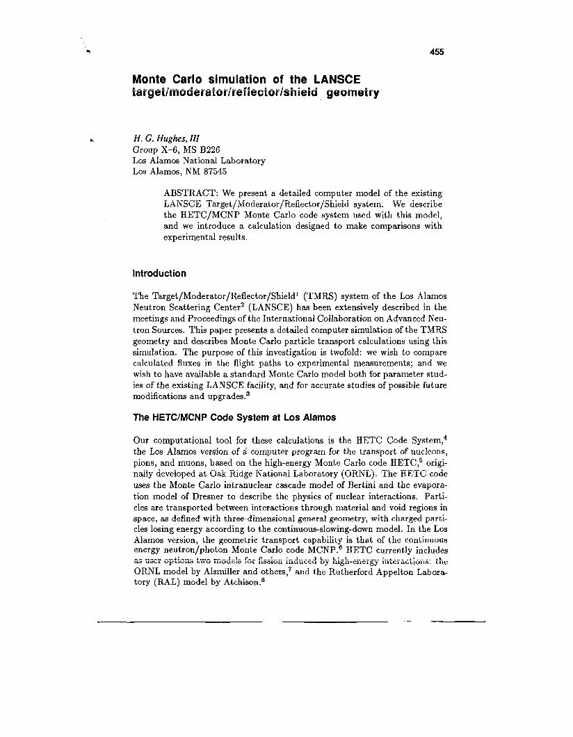
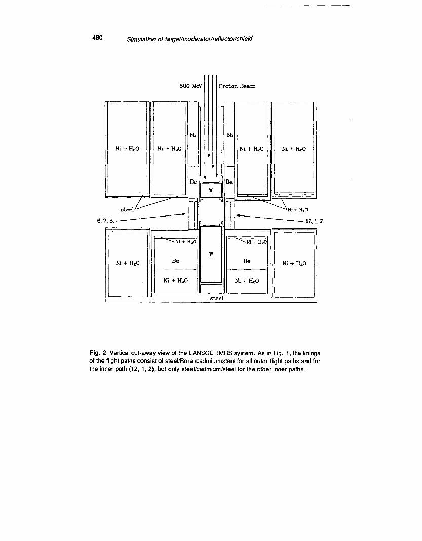
Figures l-2 show, respectively, a horizontal and a vertical cut-away view of the LANSCE geometry. Many of the unique features of the TMRS system are shown in these pictures. For example, in Fig. 1 one can see the “high-resolution” water moderator serving flight paths 12, 1, and 2, with its gadolinium poison at 1.5 cm and its complete decoupler/liner of cadmium and boron. By contrast, the cadmium and boron layers for the two “high-intensity” water moderators serving flight paths 3, 4, 5 and 6, 7, 8, are present only in the outer walls of the lines of sight. For these moderators, the gadolinium poison is at 2.5 cm.
The cold moderator containing liquid para hydrogen at 20’ K has no poison, and flight path walls similar to the two high-intensity moderators. In Fig. 2, one can see the two unequal segments of the target, the flux-trap arrangement of the moderators (not adjacent to the target), and additional details of the beryllium and nickel reflector/shield design. All of these details and more are present in the geometric model used in the Monte Carlo simulation.
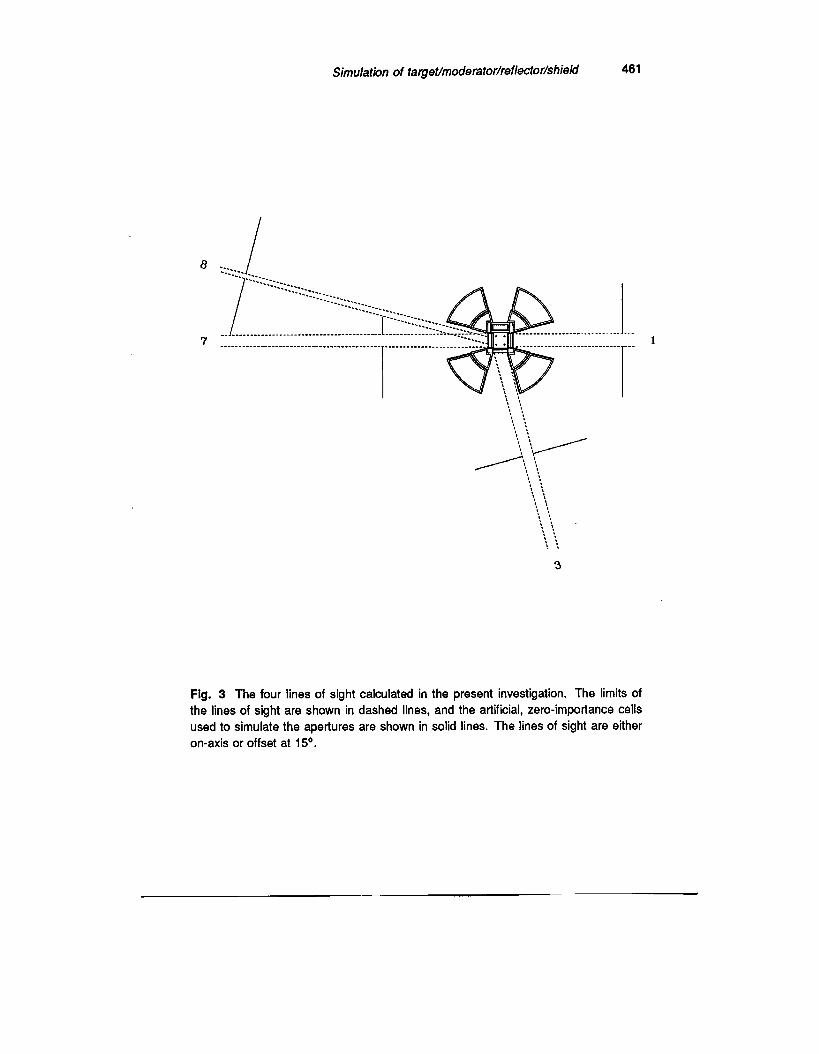
Figure 3 shows the four flight paths studied in the present investigation. These
are flight path 1, viewing the high-resolution moderator, and flight paths 3,
458 Simulation of target/moderator/reflector/shieM
TABLE I. Materials used in the TMRS model.
Material Ml M2
M3 M4 M5 M6 M7 M8 M9 Ml0
Ml1 Ml2 Ml3 Ml4
Material Ml I M2
M3 M4 M5 M6 M7 M8 M9 Ml0
Ml1 Ml2 Ml3 Ml4
Component nuclides and atom fractions. Ni : 1.00000 C: 0.00460
Simulation of targ8t/moderator/reflector/shi8fd 459
Fig. 1 Horizontal cut-away view of the LANSCE TMRS system. The layer of Boral (material 8 in Table I) is present in the outer walls of all four flight paths, but in the inner wall only for flight path (12, 1, 2).
460 Simulatbn of target/moderator/reflector/shield
Ni + Hz0
600 MeV Proton Beam
Ni + Hz0 Ni t Hz0
Fig. 2 Vertical cut-away view of the LANSCE TMRS system. As in Fig. 1, the linings
of the flight paths consist of steel/Boral/cadmium/steel for all outer flight paths and for
the inner path (12, I, 2), but only steel/cadmium/steel for the other inner paths.
Simulation of target/moderator/reflector/shield 461
Fig. 3 The four lines of sight calculated in the present investigation. The limits of the lines of sight are shown in dashed lines, and the artificial, zero-importance cells used to simulate the apertures are shown in solid lines. The lines of sight are either on-axis or offset at 15O.
462 Simulatrbn of target/moderator/reflector/shield
7, and 8, viewing the two high-intensity moderators. Calculations of point
detector responses at appropriate locations on the flight paths simulate experi-
mental measurements of neutron fluxes. We will return to the subject of point detectors and the modeling of apertures in the next section.
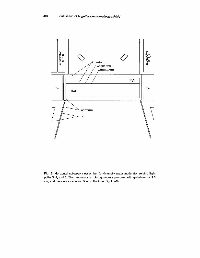
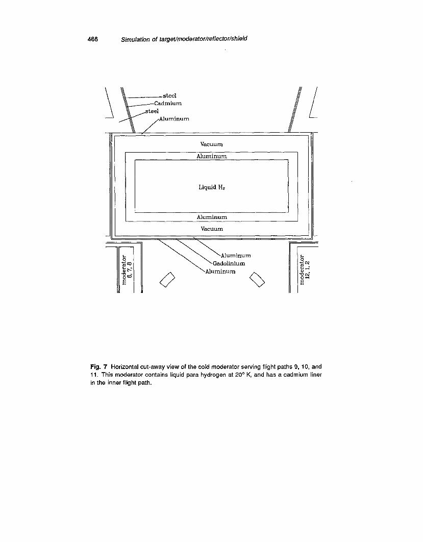
At an expanded scale, Figs. 4-7 show, in order, the high-resolution moderator serving flight paths 12, 1, and 2; the high-intensity moderator serving 3, 4, and 5; the high-intensity moderator serving 6, 7, and 8; and the cold moderator serving 9, 10, and 11. The previously mentioned features of these moderators are more easily seen (and labeled) in these pictures. To facilitate comparison, these four figures are all presented at the same scale.
The Monte Carlo Calculation
One purpose of this investigation was to compare calculated fluxes in the flight
paths with experimental measurements. The experiments consisted of mea-
surements of the 1-eV flux from gold foil activation. These measurements were made in flight paths 1, 3, 7, and 8, at various distances from the moderators, and with various fields of view. The experimental situation is described in more detail in Ref. 9.
To simulate each flux measurement, a point detector tally was used in the MCNP phase of the Monte Carlo calculation. The detector was placed on the center line of the flight path, at a distance from the moderator corresponding to the location of the foil. In a point detector calculation, every interaction of a neutron in specified cells makes a virtual contribution to the detector tally, even when the probability of a neutron actually reaching the detector is small. Thus the response of a small, distant detector may be calculated accurately for situations in which the direct (analogue) simulation of the transport would be prohibitively expensive. The point detector is a tally option of h/ICNP which is not implemented in HETC. Fortunately, all of the neutron transport below
20 MeV is handled by the MCNP phase, so that this tally is available in the
present situation.
In addition, the apertures defining the fields of view for the four measurements were simulated in the Monte Carlo calculations. This was done by the intro- duction of artificial cells outside the ThiIRS geometry to represent the shielding material blocking the neutrons outside of the fields of view. The artificial cells were given zero importance, which instructs the hIonte Carlo code to termi- nate any entering particle history. Thus only neutrons passing through the open aperture are allowed to contribute to the point detectors. This arrange- ment is illustrated in Fig. 3, showing the constraining zero-importance cells outside the TMRS. The limits of the lines of sight thereby defined are shown as dashed lines.
Simulation of target/moderator/reflector/shield 463
-
/
/
Hz0
/
_--Aluminum
,Gadolinium
7 Aluminum
moderator 9.10, 11 1/p-
steel
moderator 3,4,5
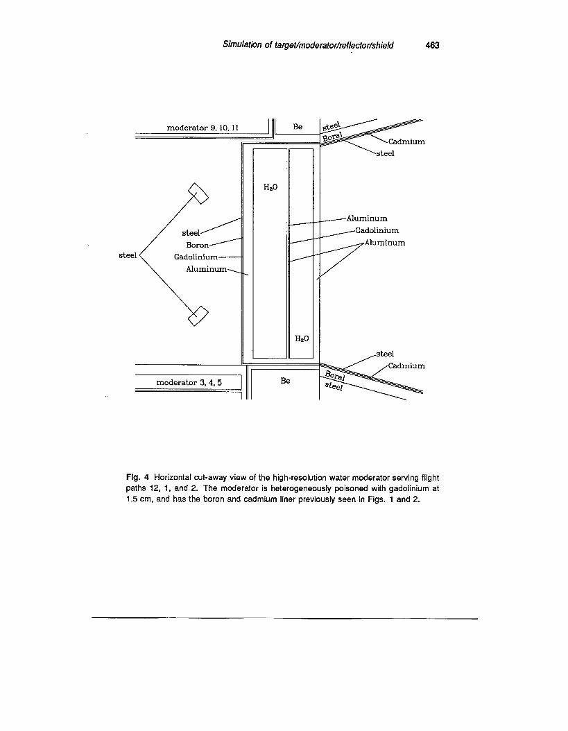
Fig. 4 Horizontal cut-away view of the high-resolution water moderator serving flight
paths 12, 1, and 2. The moderator is heterogeneously poisoned with gadolinium at
1.5 cm, and has the boron and cadmium liner previously seen in Figs. 1 and 2.
464 Simulation of target/moderator/reflector/shield
-
Be Be Hz0
\
7
- 11 ,// / / Aluminum = __
II
Hz0
0 /Aluminum
II // ,Gadolinium
Fig. 5 Horizontal cut-away view of the high-intensity water moderator serving flight
paths 3, 4, and 5. This moderator is heterogeneously poisoned with gadolinium at 2.5
cm, and has only a cadmium liner in the inner flight path.
Simulation of target/moderator/reflector/shield 465
steel /
Aluminum L
Gadolinium N
Aluminum-
moderator 9.10.11
Hz0
Hz0
0
‘-“\Cadmium
1 Aluminum
0
moderator 3,4.5
Fig. 6 Horizontal cut-away view of the high-intensity water moderator serving flight paths 6, 7, and 8. The poison and liner are similar to those in the other high-intensity moderator, shown in Fig. 5.
466 Simulation of targeUmoderator/reflecior/shield
Vacuum
Aluminum
I Liquid Hz
\+,
steel Cadmium
steel Aluminum
Aluminum
Vacuum
Aluminum
\’ Gadolinium \Aluminum
Fig. 7 Horizontal cut-away view of the cold moderator serving flight paths 9, 10, and
11. This moderator contains liquid para hydrogen at 20’ K, and has a cadmium liner
in the inner flight path.
Simulation of taget/moderator/reflector/shieM 467
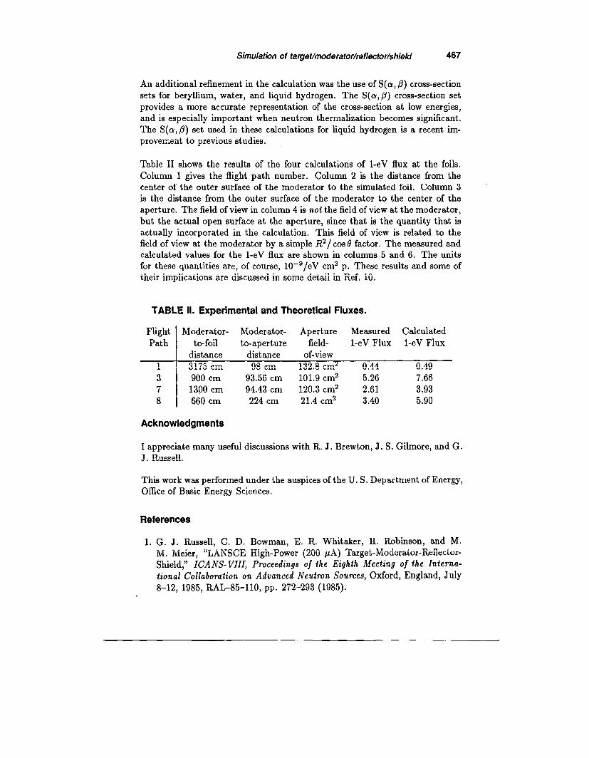
An additional refinement in the calculation was the use of S(CX, ,@ cross-section sets for beryllium, water, and liquid hydrogen. The S(o,p) cross-section set provides a more accurate representation of the cross-section at low energies, and is especially important when neutron thermalization becomes significant. The S(cr,/3) set used in these calculations for liquid hydrogen is a recent im- provement to previous studies.
Table II shows the results of the four calculations of 1-eV flux at the foils.
Column 1 gives the flight path number. Column 2 is the distance from the center of the outer surface of the moderator to the simulated foil. Column 3 is the distance from the outer surface of the moderator to the center of the aperture. The field of view in column 4 is not the field of view at the moderator, but the actual open surface at the aperture, since that is the quantity that is actually incorporated in the calculation. This field of view is related to the field of view at the moderator by a simple R2/cosB factor. The measured and calculated values for the 1-eV flux are shown in columns 5 and 6. The units for these quantities are, of course, 10sg/eV cm2 p. These results and some of their implications are discussed in some detail in Ref. 10.
900 cm 93.56 cm 101.9 cm2 5.26 7.66 1390 cm 94.43 cm 120.3 cm2 2.61 3.93 660 cm 224 cm 21.4 cm2 3.40 5.90
Acknowledgments
I appreciate many useful discussions with R. J. Brewton, J. S. Gilmore, and G. J . Russell.
This work was performed under the auspices of the U. S. Department of Energy, Office of Basic Energy Sciences.
References
1. G. J. Russell, C. D. Bowman, E. R. Whitaker, II. Robinson, and M. M. Meier, “LANSCE High-Power (200 PA) Target-Moderator-Reflector- Shield,” ICANS-VIII, Proceedings of the Eighth Meeting of the Intema- tional Collaboration on Advanced Neutron Sources, Oxford, England, July
8-12, 1985, RAL-85-110, pp. 272-293 (1985).
466 Simulation of tageUmoderator/refbctor/shield
2.
3.
4.
5.
F. A. Morse, “Status Report on LANSCE, 1986,” ICANS-IX, Proceedings of the Ninth Meeting of the International Collaboration on Advanced Neu- tron Sources, SIN, Villigen, Switzerland, September 22-26, 1986, ISBN
3-907998-01-4, pp. 31-43 (July 1987). G. J. Russell, H. Robinson, G. L. Legate, R. Woods, E. R. Whitaker, A. Bridge, K. J. Hughes, and R. D. Neef, “The LANSCE Target System,”
ICANS-IX, Proceedings of the Ninth Meeting of the International Collabo- ration on Advanced Neutron Sources, SIN, Villigen, Switzerland, September 22-26, 1986, ISBN 3-907998-01-4, pp. 177-244 (July 1987). R. E. Prael, and H. Lichtenstein, “User Guide to the HETC Code System,” Los Alamos National Laboratory interim documentation (June 15, 1987). Radiation Shielding Information Center, “RSIC Computer Code Collection:
HETC, Monte Carlo High-Energy Nucleon-Meson Transport Code,” Oak Ridge National Laboratory report CCC-178, Rev. (August 1977).
6. J. F. Briesmeister, editor, “MCNP - A General Monte Carlo Code for
Neutron and Photon Transport,” Los Alamos National Laboratory report
LA-7396-M, Rev. 2 (September 1986). 7. J. Barish, T. A. Gabriel, F. S. Alsmiller, and R. G. Alsmiller, Jr., “HET-
FIS High-Energy Nucleon-Meson Transport Code with Fission,” Oak Ridge
National Laboratory report ORNL/TM-7882 (July 1981). 8. F. Atchison, “Spallation and Fission in Heavy Metal Nuclei under Medium
Energy Proton Bombardment,” in Targets for Neutron Beam Spallation Sources, Jiil-Conf-34, Kernforschungsanlage Jiilich GmbH (June 1980).
9. J. S. Gilmore, R. A. Robinson, and G. J. Russell, “Experimental Determi- nation of Neutron Beam Fluxes at LANSCE from Gold Foil Activation,” in these proceedings.
10. G. J. Russell, J. S. Gilmore, H. Robinson, G. L. Legate, A. Bridge, R. J. Sanchez, R. J. Brewton, R. Woods, and H. G. Hughes, III, “LANSCE Target System Performance,” in these proceedings.