11
1 DOC-0139N MONXT Siemens To Delta Retrofit Kit

1 DOC-0139N
MONXT Siemens To Delta Retrofit Kit
2 DOC-0139N
Table Of Contents A. Equipment ............................................................................................................................................. 3
B. Overview ............................................................................................................................................... 4
1. Equipment ......................................................................................................................................... 4
2. Hanger Assembly Locations .............................................................................................................. 5
3. Header Modifications ....................................................................................................................... 6
4. Bracket Mounting ............................................................................................................................. 7
5. Mounting Assemblies ........................................................................................................................ 8
6. Wiring ................................................................................................................................................ 9
7. Adjustments .................................................................................................................................... 11
3 DOC-0139N
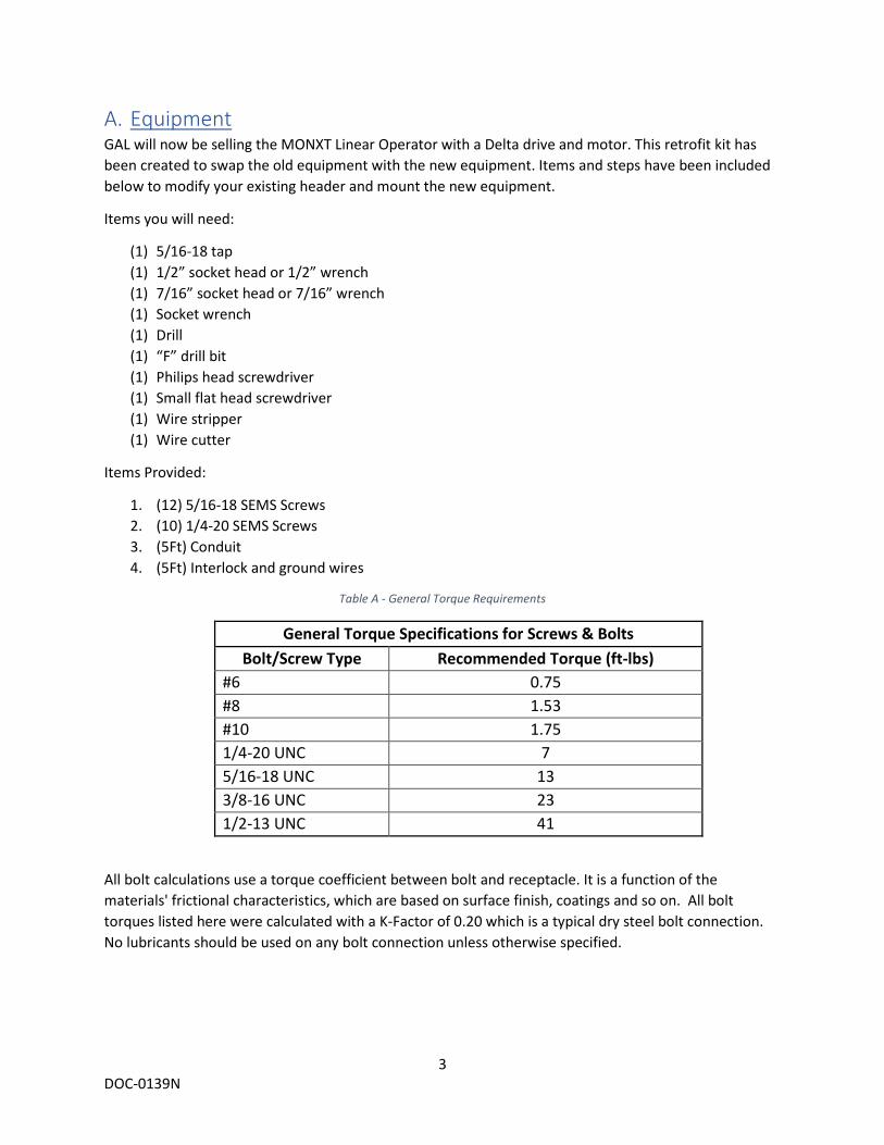
A. Equipment GAL will now be selling the MONXT Linear Operator with a Delta drive and motor. This retrofit kit has been created to swap the old equipment with the new equipment. Items and steps have been included below to modify your existing header and mount the new equipment.
Items you will need:
(1) 5/16-18 tap (1) 1/2” socket head or 1/2” wrench (1) 7/16” socket head or 7/16” wrench (1) Socket wrench (1) Drill (1) “F” drill bit (1) Philips head screwdriver (1) Small flat head screwdriver (1) Wire stripper (1) Wire cutter
Items Provided:
1. (12) 5/16-18 SEMS Screws 2. (10) 1/4-20 SEMS Screws 3. (5Ft) Conduit 4. (5Ft) Interlock and ground wires
Table A - General Torque Requirements
General Torque Specifications for Screws & Bolts Bolt/Screw Type Recommended Torque (ft-lbs)
#6 0.75 #8 1.53 #10 1.75 1/4-20 UNC 7 5/16-18 UNC 13 3/8-16 UNC 23 1/2-13 UNC 41
All bolt calculations use a torque coefficient between bolt and receptacle. It is a function of the materials' frictional characteristics, which are based on surface finish, coatings and so on. All bolt torques listed here were calculated with a K-Factor of 0.20 which is a typical dry steel bolt connection. No lubricants should be used on any bolt connection unless otherwise specified.

4 DOC-0139N
B. Overview You currently have a similar setup to the operator shown below:
1. Equipment Your operator will need to be modified/replaced with new equipment provided as shown on the tables below:
Item Description old part number new part number
A MONXT Header No Change B SS/CP Motor bracket OPL-1007N OPL-1078N C SS/CP Tensioner bracket OPL-1006N OPL-1077N D Motor assembly OPL-0101N OPL-0133N E Tensioner Assembly OPL-0103N OPL-0131N F Control box OPL-0105N OPL-0132N
Table B - SS/CP Application
Figure 1 – Single speed left hand MONXT Operator

5 DOC-0139N
For reference, the part numbers for the kits that include all necessary components are listed below:
OPL-0140N – For SS/CP operators
OPL-0141N – For 2S/2SCP operators
2. Hanger Assembly Locations Table D, shown below, helps identify where each assembly is mounted based on the hand of the operator. For CP/2SCP operators, the motor assembly is always on the left side of the hanger and the tensioner on the right side of the hanger. Figures 2-4, depict the different job set ups for SS, 2S and CP operators. The orange arrow represents the motor assembly, whereas, the green arrow shows the tensioner assembly.
Table D - Motor and tensioner assembly locations on hanger
Figure 2 – Left hand SS Operator
Figure 3 – Right Hand SS Operator
Item Description old part number new part number A MONXT header No Change B 2S/2SCP motor bracket OPL-1009N OPL-1082N C 2S/2SCP tensioner bracket OPL-1008N OPL-1081N D Motor assembly OPL-0101N OPL-0133N E Tensioner assembly OPL-0103N OPL-0131N F Control box OPL-0105N OPL-0132N
Table C - 2S/2SCP Application
Hand Left Side Right Side Left hand Operator Motor Tensioner
Right Hand Operator Tensioner Motor CP/2SCP Operator Motor Tensioner
6 DOC-0139N
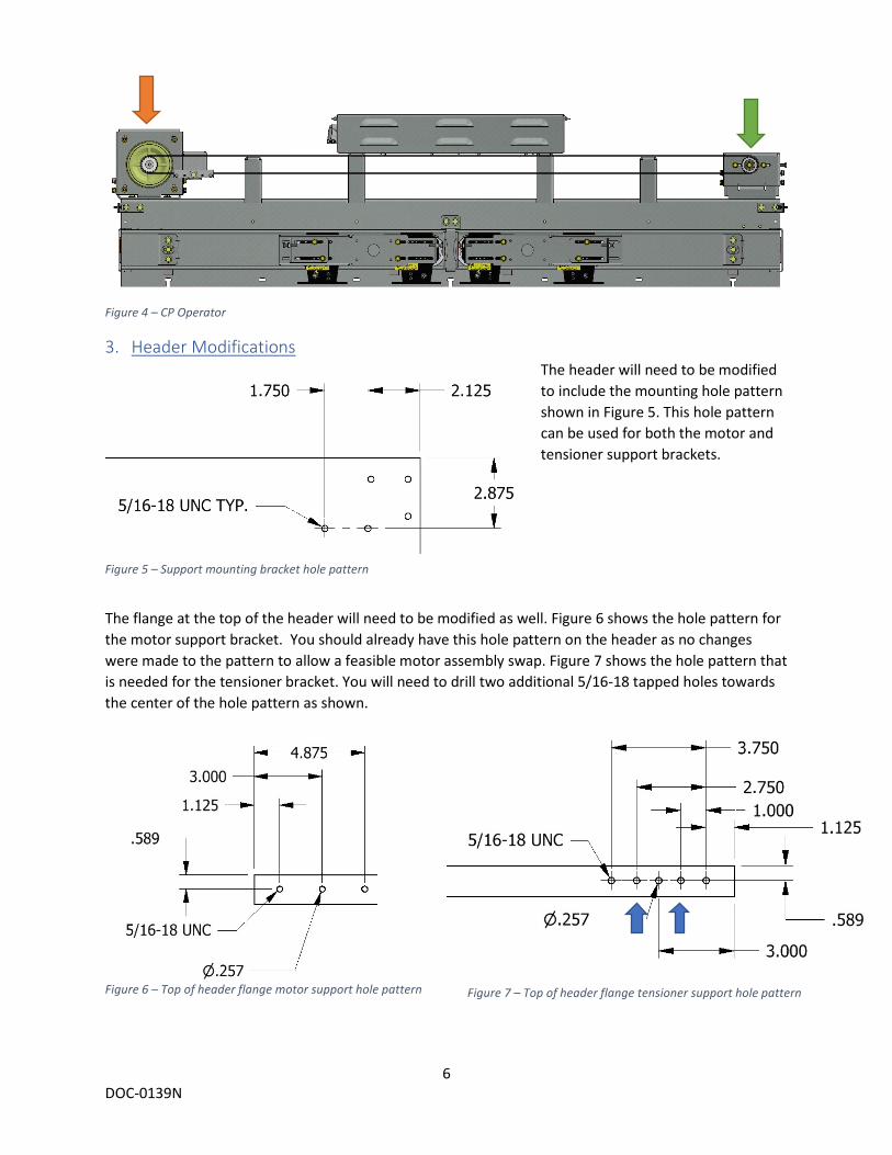
Figure 4 – CP Operator
3. Header ModificationsThe header will need to be modified to include the mounting hole pattern shown in Figure 5. This hole pattern can be used for both the motor and tensioner support brackets.
The flange at the top of the header will need to be modified as well. Figure 6 shows the hole pattern for the motor support bracket. You should already have this hole pattern on the header as no changes were made to the pattern to allow a feasible motor assembly swap. Figure 7 shows the hole pattern that is needed for the tensioner bracket. You will need to drill two additional 5/16-18 tapped holes towards the center of the hole pattern as shown.
Figure 5 – Support mounting bracket hole pattern
Figure 6 – Top of header flange motor support hole pattern Figure 7 – Top of header flange tensioner support hole pattern
7 DOC-0139N
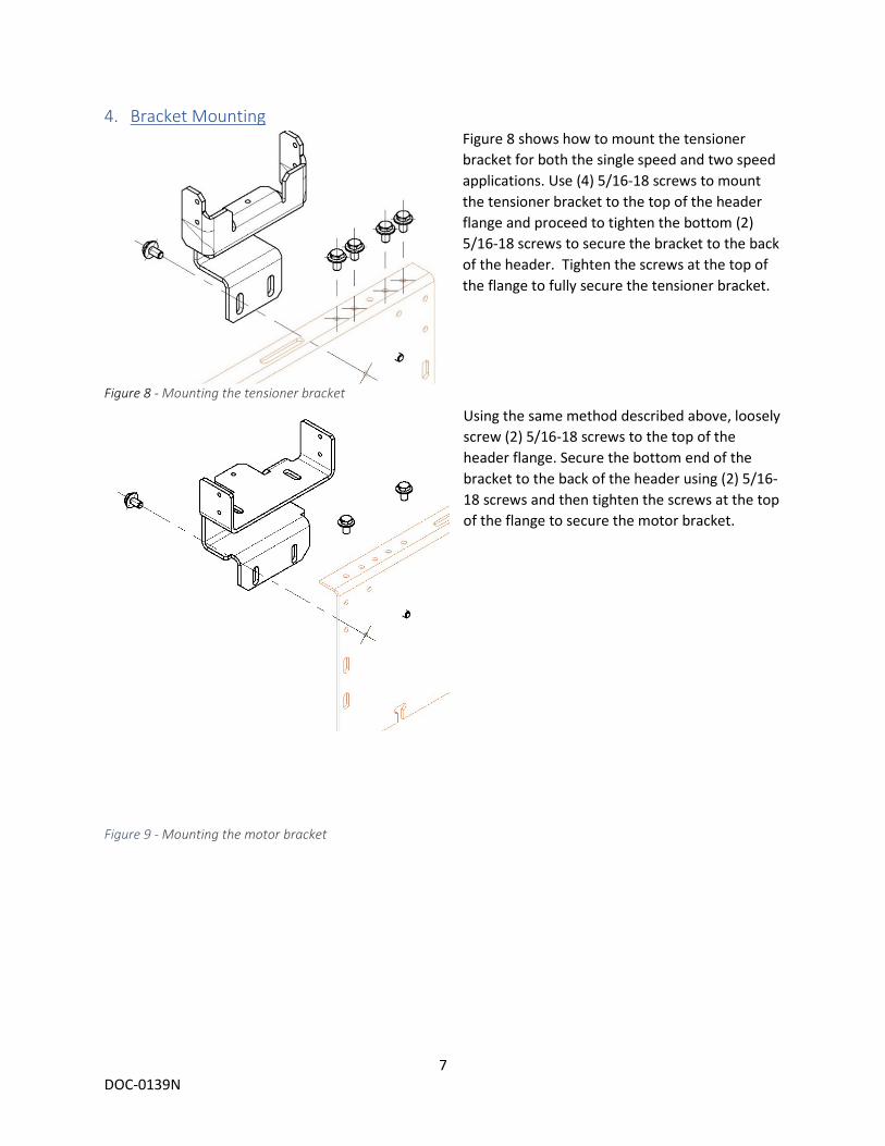
4. Bracket Mounting Figure 8 shows how to mount the tensioner bracket for both the single speed and two speed applications. Use (4) 5/16-18 screws to mount the tensioner bracket to the top of the header flange and proceed to tighten the bottom (2) 5/16-18 screws to secure the bracket to the back of the header. Tighten the screws at the top of the flange to fully secure the tensioner bracket.
Using the same method described above, loosely screw (2) 5/16-18 screws to the top of the header flange. Secure the bottom end of the bracket to the back of the header using (2) 5/16-18 screws and then tighten the screws at the top of the flange to secure the motor bracket.
Figure 8 - Mounting the tensioner bracket
Figure 9 - Mounting the motor bracket

8 DOC-0139N
5. Mounting Assemblies
Once the tensioner support bracket is secured to the hanger, place the tensioner assembly on top and secure the assembly using the (5) ¼-20 screws. As shown in Figure 10, hand tighten the two screws on each side and one screw on the back of the assembly. Figure 11 shows the final mounting position for the tensioner assembly, make sure to also loosen the two front screws on the tensioner assembly shown on Figure 11 as you will need to mount the belt, adjust your clutch and increase the tension on the belt.
Make sure you are mounting the correct handed assembly if you have a handed operator. Figure 12 represents a left-hand application and Figure 13 represents a right-hand application. Figure 14 shows how to mount the motor assembly on to the motor bracket, loosely tighten the two screws on the side and the one on the back as you will need to adjust your belt with the clutch after you put on the belt on the operator. Figure 15 displays the correct way to mount the motor assembly to the motor bracket.
Figure 11 – Mounted tensioner assembly
Figure 12 – Motor Assembly Left Hand Orientation
Figure 10 - Unmounted tensioner assembly
Figure 13 - Motor Assembly Right Hand Orientation
Figure 14 – Unmounted Motor Assembly Figure 15 – Mounted Motor Assembly
9 DOC-0139N
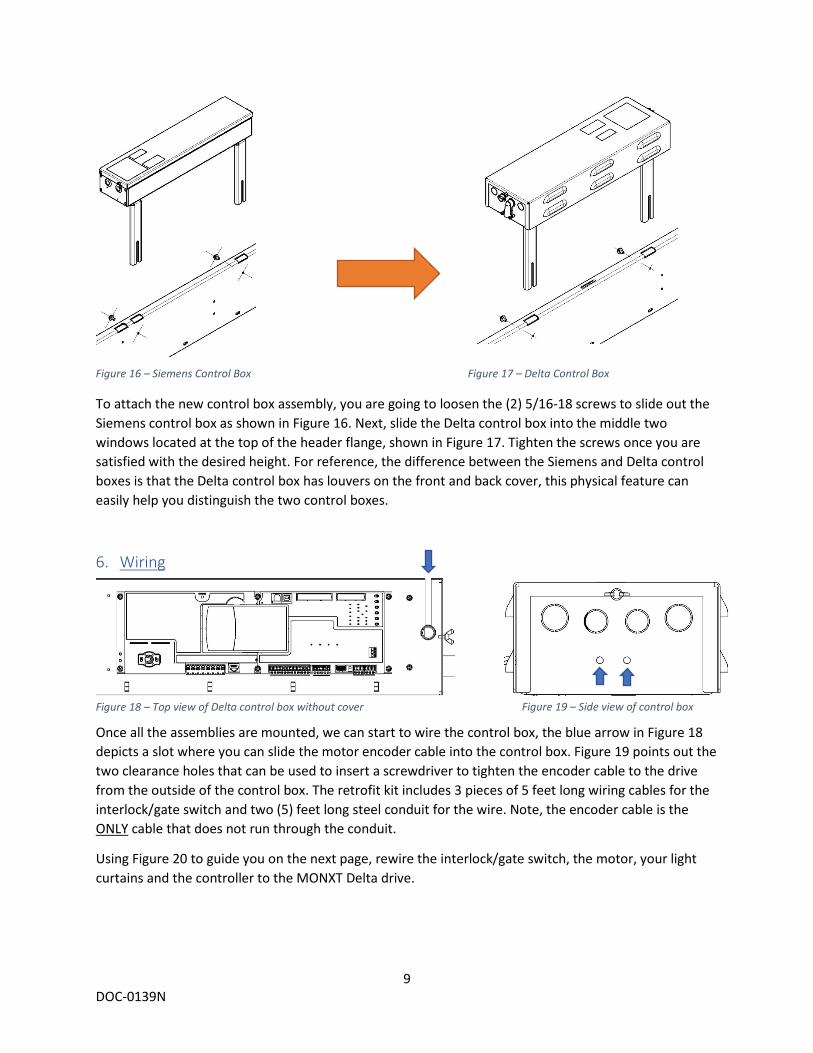
To attach the new control box assembly, you are going to loosen the (2) 5/16-18 screws to slide out the Siemens control box as shown in Figure 16. Next, slide the Delta control box into the middle two windows located at the top of the header flange, shown in Figure 17. Tighten the screws once you are satisfied with the desired height. For reference, the difference between the Siemens and Delta control boxes is that the Delta control box has louvers on the front and back cover, this physical feature can easily help you distinguish the two control boxes.
6. Wiring
Once all the assemblies are mounted, we can start to wire the control box, the blue arrow in Figure 18 depicts a slot where you can slide the motor encoder cable into the control box. Figure 19 points out the two clearance holes that can be used to insert a screwdriver to tighten the encoder cable to the drive from the outside of the control box. The retrofit kit includes 3 pieces of 5 feet long wiring cables for the interlock/gate switch and two (5) feet long steel conduit for the wire. Note, the encoder cable is the ONLY cable that does not run through the conduit.
Using Figure 20 to guide you on the next page, rewire the interlock/gate switch, the motor, your light curtains and the controller to the MONXT Delta drive.
Figure 16 – Siemens Control Box Figure 17 – Delta Control Box
Figure 18 – Top view of Delta control box without cover Figure 19 – Side view of control box

10 DOC-0139N
Figure 20 – Delta drive wiring diagram

11 DOC-0139N
7. Adjustments From this point on, you can use the MONXT Manual to continue the setup to your operator. The Part number for the document is listed below:
MONXT Manual: DOC-0137N

![jaspens.files.wordpress.com fileac drives, plc [panel assy] retrofit crane control in pt. indah kiat pulp & paper, tbk.. ups siemens ... grinding machine in pt. sulzer hickham indonesia).](https://static.documents.pub/doc/80x56/5ccbb86288c9937f4b8dcf63/drives-plc-panel-assy-retrofit-crane-control-in-pt-indah-kiat-pulp-paper.jpg)


