MOORING SYSTEM DESIGN FOR A WAVE ENERGY CONVERTER Prepared For: Natural Resources Canada Marine Energy Technology Renewable and Integrated Energy System CanmetENERGY – Ottawa 580 Booth Street, Ottawa, ON, Canada, K1A 0E4 Prepared By: Bill Rawlings and Voytek Klaptocz, Mavi Innovations Inc. August 31 st , 2010
Transcript
MOORING SYSTEM DESIGN FOR A
WAVE ENERGY CONVERTER
Prepared For: Natural Resources Canada
Marine Energy Technology Renewable and Integrated Energy System
Prepared By: Bill Rawlings and Voytek Klaptocz, Mavi Innovations Inc.
August 31st, 2010
Mooring System Design for a Wave Energy Converter August 31, 2010
i
DISCLAIMER
Neither CanmetENERGY nor any of its employees makes any warranty, express or implied, or assumes any legal liability or responsibility for the accuracy, completeness or usefulness of the contents in the report. Reference in the report to any specific commercial product, process, service or organization does not necessarily constitute or imply endorsement, recommendation or favouring by CanmetENERGY. The views and opinions of authors expressed in this report do not necessarily state or reflect those of CanmetENERGY.
Mooring System Design for a Wave Energy Converter August 31, 2010
ii
ACKNOWLEDGEMENTS
The work performed for this report was funded under the Program for Renewable Energy Technologies allocated by the PERD POL 5.1.1 Distributed Power Generation Portfolio Committee. In-kind services were contributed by other organizations and including CanmetENERGY-Ottawa representatives.
The following experts and organizations conducted the study:
Project lead: Bill Rawlings and Voytek Klaptocz, Mavi Innovations Inc.
In association with: Ryan Nicoll, Dynamic Systems Analysis Scott Beatty, Ocean Engineering Research Group, University of Victoria
Mooring System Design for a Wave Energy Converter August 31, 2010
iii
Summary
This report provides a summary of the collaborative work done by Mavi Innovations Inc., Dynamic Systems Analysis (DSA) and a Scott Beatty, a PhD candidate from the University of Victoria (UVic) Ocean Engineering Research Group, on mooring system design for tidal energy converters (TECs) and wave energy converters (WECs). This report specifically deals with the WEC mooring analysis. A separate report was issued documenting the design of a TEC mooring system. The majority of the work was funded by Natural Resources Canada with an additional portion done on an in-kind basis by each company.
This report documents the modeling work done by DSA to develop a mooring system for a generic heaving wave energy point absorber designed by UVic researchers. The primary objective of this work was to analyze the response of a full scale mooring system and subsequently develop a scaling methodology for experimentally testing the WEC in a towing tank or offshore basin.
Mooring System Design for a Wave Energy Converter August 31, 2010
iv
TABLE OF CONTENTS
Summary...................................................................................................................................................iii List of Figures............................................................................................................................................ v List of Tables............................................................................................................................................. v 1 Introduction ....................................................................................................................................... 1 2 WEC device....................................................................................................................................... 2 3 WEC Model....................................................................................................................................... 3 4 Mooring System Design .................................................................................................................... 4
Appendix C: Scaled WEC RAO data ...................................................................................................... 17 16mm chain mooring........................................................................................................................... 17 18 mm chain mooring.......................................................................................................................... 18 22 mm chain mooring.......................................................................................................................... 19 24 mm chain mooring.......................................................................................................................... 20 Ideal mooring....................................................................................................................................... 21
Mooring System Design for a Wave Energy Converter August 31, 2010
v
LIST OF FIGURES Figure 3-1: 2 body point absorber WEC.................................................................................................... 2
Figure 3-2: Chain catenary connected to WEC float................................................................................. 5
Figure 3-3: Chain catenary connected to WEC spar ................................................................................. 5
Figure 3-4: Chain catenary with synthetic rope bridle connected to WEC float and spar......................... 6
LIST OF TABLES Table 3-1: Full scale WEC mooring properties ......................................................................................... 7
Mooring System Design for a Wave Energy Converter August 31, 2010
1
1 INTRODUCTION The analysis and design of Wave Energy Converters (WECs) is more difficult compared to tidal energy converters due to increased platform complexity, system motions, and survival design requirements from exposed installation location. Developing a complete WEC system typically involves the use of various simulations modeling techniques and scaled model physical tests before deploying a prototype in the ocean.
The generic heaving point absorber WEC used for the work presented in this report was designed by faculty and graduate students from the Ocean Engineering Research Group from the University of Victoria, Canada, through the use of 1D frequency-domain simulation analysis tools. A full 3D model of the WEC was then created by DSA in order to design the mooring system. To facilitate future studies of the WEC system as well as validation of the work done to date, a scaled version of the WEC and mooring that could be tested in a wave tank facility was created to quantify performance.
To complete this process, two key iterative design cycles were completed. The first design cycle generated a mooring design by subjecting the system to extreme ocean wave conditions. This ensures the mooring will satisfy the most important design requirement of survivability. With the mooring design finalized, the full scale WEC with mooring was then subjected to a series of sea states to quantify the response of the system.
The second design cycle was to establish the scaled mooring system. Froude scaling theory allows a scale model to be produced with equivalent dynamics to the full scale system. However, the mooring system is too complex to be easily scaled due to competing factors such as hydrodynamic loading, weight, and stiffness. As a result, iteration on the scaled mooring chain size was required to investigate the effect on WEC response and attempt to minimize the error from the full scale system.
Mooring System Design for a Wave Energy Converter August 31, 2010
2 WEC DEVICE The WEC selected for study is a simple 2-body point absorber illustrated in Figure 2-1. A large waterline-diameter low weight float is designed to follow ocean waves as they pass. The small waterline-diameter high mass spar is designed to be less sensitive to waves. Successful energy capture evolves from the relative motion between the float and spar with the use of a power take-off system such as hydraulic rams.
There are several commercial WEC devices that use this generic mode of operation including: WaveBob, Ocean Power Technology, and SyncWave Systems.
The physical parameters including dimensions and masses were provided by UVic to form the basis for the generic WEC model studies in this report.
Figure 2-1: 2 body point absorber WEC
2
Mooring System Design for a Wave Energy Converter August 31, 2010
3
3 WEC MODEL The WEC was represented with an articulated rigid body model using Proteus DS, DSA’s in-house modeling software. The articulated body is comprised of several rigid body components that are connected to each other through joints that constrain the system.
The generic point absorber WEC that was used has two key components: the float and the spar. The float is designed to follow the ocean surface while the spar is designed to be a body against which the float reacts against to generate electricity. The two bodies are constrained by a prismatic joint, which means they only move relative to each in heave as an ocean wave passes.
A surface mesh of the WEC float and spar was generated to automatically calculate buoyancy, drag, and added mass loads. Dimensions and masses were provided by UVic.
The mooring model was represented with the same finite element cable model.
Mooring System Design for a Wave Energy Converter August 31, 2010
4
4 MOORING SYSTEM DESIGN
4.1 DESIGN CYCLE 1: MOORING CONCEPT SELECTION
The interaction of the mooring system with the WEC is critical for effective power capture; even more critical is that the mooring must hold the system on station in extreme ocean conditions. As such, the primary design objective of the mooring is to ensure survival of the system. With a mooring designed for survival conditions, the dynamics during nominal ocean conditions are studied and the influence of the mooring is discerned.
A three point mooring was used for redundancy, to reduce the watch circle of the WEC, and to help isolate power cables from any dynamic loading. The wave direction was aligned to load only one of the mooring legs to ensure a conservative analysis. To represent survival conditions, a water depth of 40 m was used along with a 10 metre significant wave height with 15 second period based on data provided by UVic. In addition, a 1.5 metre/second uniform current was superimposed on the wave field with the same direction as the wave propagation such that only a single mooring line leg was loaded. In all cases, the float was locked to the spar to mimic actual WEC survival configuration that avoids damaging power take off components and prevents end-stop collisions. The key performance parameters are mooring tensions and WEC tilt angle.
The following mooring concepts were analyzed:
1. catenary chain connected to the float 2. catenary chain connected to the bottom of the spar 3. synthetic bridle connected both to the float and to the bottom of the spar
Of these 3 concepts, only the bridle mooring design proved to be a viable solution. Detailed results are presented in the following sections.
4.1.1 CHAIN CATENARY – FLOAT
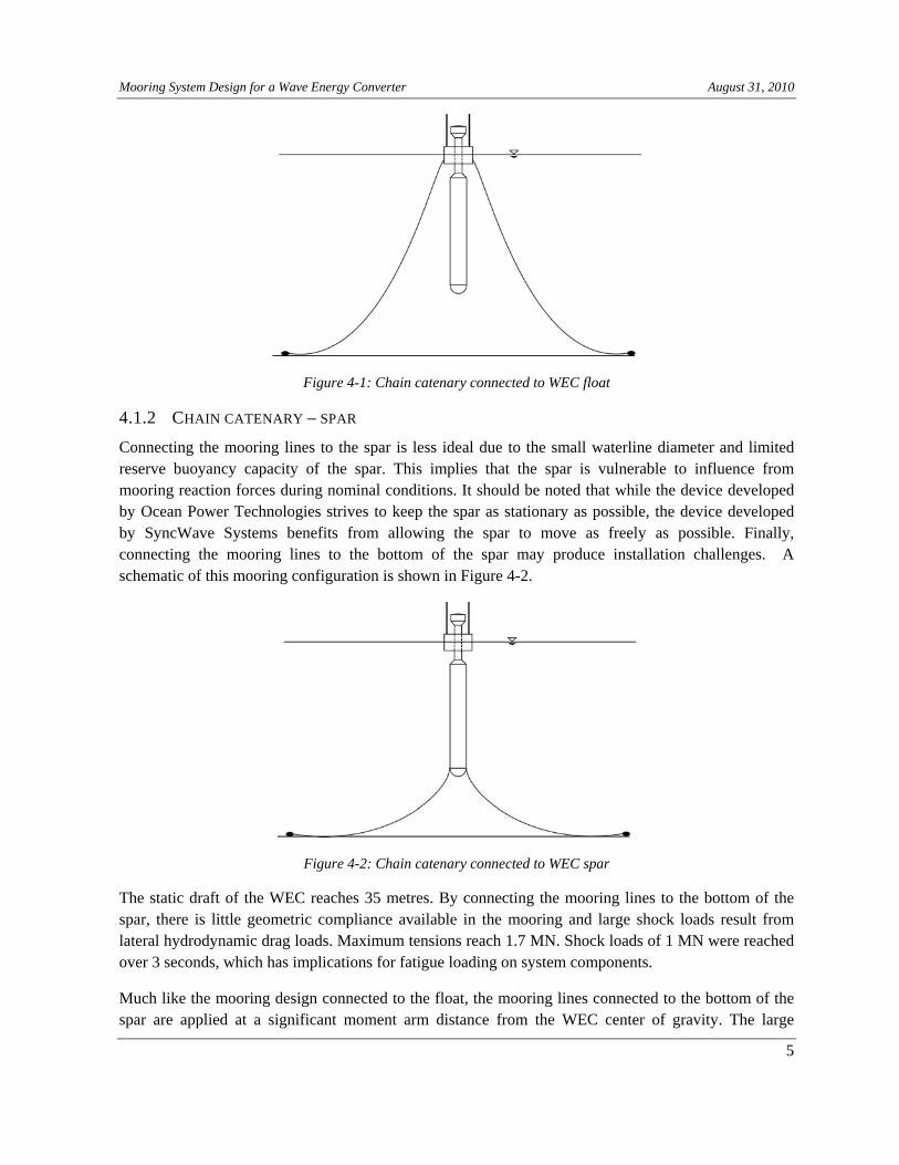
Connecting the mooring lines to the float is ideal as the float can be designed to have extensive reserve buoyancy to handle the static load of the mooring. Due to the relatively shallow water, a significantly length of chain was required to avoid full anchor line lift. A schematic of the mooring is shown in Figure 4-1.
The considerable submerged area of the spar resulted in large hydrodynamic loading. The maximum calculated loading on the mooring line was 0.9 MN. The large resulting mooring reaction load and application point far above the system center of mass resulted in the largest tilt motion, reaching 35 degrees. This will result in contact of the WEC hull with mooring lines and catastrophic failure through self-entanglement.
Mooring System Design for a Wave Energy Converter August 31, 2010
Figure 4-1: Chain catenary connected to WEC float
4.1.2 CHAIN CATENARY – SPAR
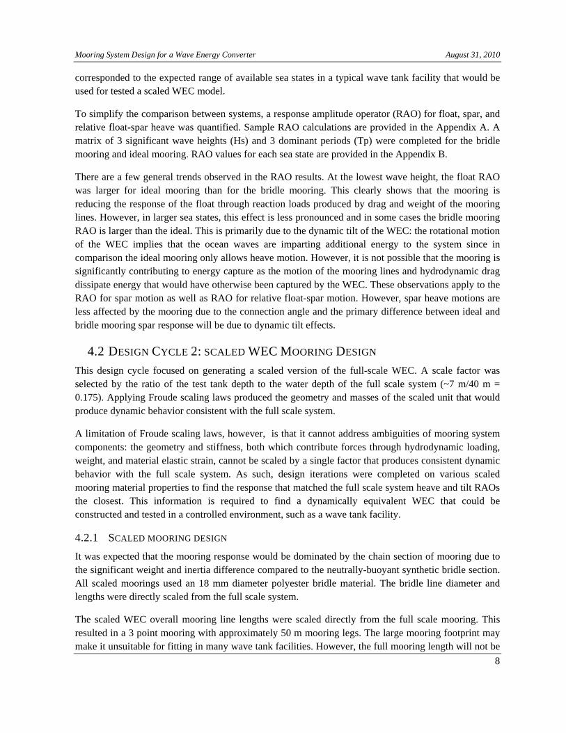
Connecting the mooring lines to the spar is less ideal due to the small waterline diameter and limited reserve buoyancy capacity of the spar. This implies that the spar is vulnerable to influence from mooring reaction forces during nominal conditions. It should be noted that while the device developed by Ocean Power Technologies strives to keep the spar as stationary as possible, the device developed by SyncWave Systems benefits from allowing the spar to move as freely as possible. Finally, connecting the mooring lines to the bottom of the spar may produce installation challenges. A schematic of this mooring configuration is shown in Figure 4-2.
Figure 4-2: Chain catenary connected to WEC spar
The static draft of the WEC reaches 35 metres. By connecting the mooring lines to the bottom of the spar, there is little geometric compliance available in the mooring and large shock loads result from lateral hydrodynamic drag loads. Maximum tensions reach 1.7 MN. Shock loads of 1 MN were reached over 3 seconds, which has implications for fatigue loading on system components.
Much like the mooring design connected to the float, the mooring lines connected to the bottom of the spar are applied at a significant moment arm distance from the WEC center of gravity. The large
5
Mooring System Design for a Wave Energy Converter August 31, 2010
mooring reaction loads in combination with hydrodynamic forces acting on the large submerged area of the spar result in WEC pitch angles as high as 45 degrees.
WEC pitch is not, however, as important for this mooring design as self-entanglement is not possible. Since the bottom of the WEC remains held in place by the mooring it provides an ideal location for attachment of the power cable to avoid dynamic loading.
4.1.3 BRIDLE – FLOAT – SPAR
The bridle mooring connects to both the float and the spar using synthetic lines instead of chain. A schematic of the mooring is shown in Figure 4-3. Synthetic lines have significantly more elastic compliance than chain, though they cannot come into contact with the sea floor without entrainment of grit that compromises filament integrity. The synthetic lines being neutrally buoyant will help reduce the influence of mooring loads during nominal ocean conditions. During extreme conditions, however, the mooring reaction load is spread over two contact points, which reduces mooring line size requirements as well as hull structural design requirements. The synthetic bridle is connected to a chain that leads to the anchor.
Figure 4-3: Chain catenary with synthetic rope bridle connected to WEC float and spar
This design is significantly more complex because the bridle leg lengths are different and the design requires that the anchors be placed far enough apart so as to provide pretension in the mooring lines. Simulation results indicate an approximate minimum of 180 kN of pretension is required to reduce shock loading in the lower bridle lines in severe conditions. However, the shorter bridle length connecting the spar means that the mooring reaction load is almost completely horizontal, which will result in marginal influence on spar dynamics in nominal ocean conditions.
The performance of this mooring system in survival conditions was found to be favorable. Maximum WEC pitch angle was 11 degrees and mooring connection points at the top and bottom of the WEC ensure that entanglement is not possible. Maximum mooring loads at the anchor reached 1.9 MN, with maximum bridle tensions reaching 1.1 MN on the float and 0.8 MN on the spar. Note that the maximum tension for this mooring system is higher when compared to the other moorings. This higher tension
6
Mooring System Design for a Wave Energy Converter August 31, 2010
7
loads are due to the increased hydrodynamic loading caused by the fact that the WEC experiences lower pitch angles.
The rate of loading is improved when compared to the chain-spar mooring design, with 1 MN loads reached in 5 seconds. While this is still severe dynamic loading, there is 40% reduction in shock loading frequency which may have important implications for fatigue loading of components.
A safety factor of 1.67 was used for the strength of mooring lines as per the American Petroleum Institute design standards for offshore mooring structures. Multiple iterations of mooring material types, diameters, and bridle length ratios were completed to find an appropriate design that meets this safety factor. The resulting mooring properties are summarized in Table 4-1 below. With the bridle length ratio given, the bridle legs reach approximately equal tension under extreme wave loading, which evenly distributes the load on the hull of the WEC and also ensures that the same synthetic mooring material can be used. Note that anchors must be placed 249.5 metres radially from the WEC to ensure proper pretension of the system. The 3 point mooring is equally spread around the WEC with 120 degrees.
Table 4-1: Full scale WEC mooring properties
Mooring segment Material Segment length
Upper bridle line 104 mm polyester 12 braid 48 m
Lower bridle line 104 mm polyester 12 braid 37.5 m
Thrash chain 92 mm grade 3 chain 212 m
4.1.4 ULL SCALE WEC RESPONSE AND INFLUENCE OF MOORING
With the bridle mooring design selected, the response of the system in an unlocked configuration was required. An idealized WEC mooring system was created in order to better understand the influence of the mooring design on potential power capture and also to compare the model created using ProteusDS to the 1D frequency domain model used by researchers at UVic.
This idealized system consists of arbitrarily constraining the WEC system to heave (vertical) motion only. It is therefore not possible to physically replicate this idealized system experimentally or in the field. This mooring is referred to as ideal as it offers no resistance to heave motions that are used to generate electricity but all other motions (including tilt) are perfectly constrained and never move in space.
By comparing the performance of the WEC with bridle mooring and the WEC with ideal mooring, an indication of performance degradation due to the presence of the mooring can be quantified. It is emphasized that the WEC with bridle mooring was allowed full 6 degrees of freedom motion with constraints naturally provided by the mooring dynamics. For both moorings, the float and spar were able to move freely relative to each other along the prismatic joint with end stops in place at 5 metres.
The WEC was unlocked to allow motion between the float and the spar and was subjected to a wide range of sea states to quantify the response. The sea states selected for the full scale system
Mooring System Design for a Wave Energy Converter August 31, 2010
8
corresponded to the expected range of available sea states in a typical wave tank facility that would be used for tested a scaled WEC model.
To simplify the comparison between systems, a response amplitude operator (RAO) for float, spar, and relative float-spar heave was quantified. Sample RAO calculations are provided in the Appendix A. A matrix of 3 significant wave heights (Hs) and 3 dominant periods (Tp) were completed for the bridle mooring and ideal mooring. RAO values for each sea state are provided in the Appendix B.
There are a few general trends observed in the RAO results. At the lowest wave height, the float RAO was larger for ideal mooring than for the bridle mooring. This clearly shows that the mooring is reducing the response of the float through reaction loads produced by drag and weight of the mooring lines. However, in larger sea states, this effect is less pronounced and in some cases the bridle mooring RAO is larger than the ideal. This is primarily due to the dynamic tilt of the WEC: the rotational motion of the WEC implies that the ocean waves are imparting additional energy to the system since in comparison the ideal mooring only allows heave motion. However, it is not possible that the mooring is significantly contributing to energy capture as the motion of the mooring lines and hydrodynamic drag dissipate energy that would have otherwise been captured by the WEC. These observations apply to the RAO for spar motion as well as RAO for relative float-spar motion. However, spar heave motions are less affected by the mooring due to the connection angle and the primary difference between ideal and bridle mooring spar response will be due to dynamic tilt effects.
4.2 DESIGN CYCLE 2: SCALED WEC MOORING DESIGN
This design cycle focused on generating a scaled version of the full-scale WEC. A scale factor was selected by the ratio of the test tank depth to the water depth of the full scale system (~7 m/40 m = 0.175). Applying Froude scaling laws produced the geometry and masses of the scaled unit that would produce dynamic behavior consistent with the full scale system.
A limitation of Froude scaling laws, however, is that it cannot address ambiguities of mooring system components: the geometry and stiffness, both which contribute forces through hydrodynamic loading, weight, and material elastic strain, cannot be scaled by a single factor that produces consistent dynamic behavior with the full scale system. As such, design iterations were completed on various scaled mooring material properties to find the response that matched the full scale system heave and tilt RAOs the closest. This information is required to find a dynamically equivalent WEC that could be constructed and tested in a controlled environment, such as a wave tank facility.
4.2.1 SCALED MOORING DESIGN
It was expected that the mooring response would be dominated by the chain section of mooring due to the significant weight and inertia difference compared to the neutrally-buoyant synthetic bridle section. All scaled moorings used an 18 mm diameter polyester bridle material. The bridle line diameter and lengths were directly scaled from the full scale system.
The scaled WEC overall mooring line lengths were scaled directly from the full scale mooring. This resulted in a 3 point mooring with approximately 50 m mooring legs. The large mooring footprint may make it unsuitable for fitting in many wave tank facilities. However, the full mooring length will not be
Mooring System Design for a Wave Energy Converter August 31, 2010
9
needed for testing in nominal operating conditions as the full mooring length is designed to be completely lifted only in the most extreme ocean conditions. When a test tank WEC version is made, only the fraction of the 50 m mooring leg length that is lifted during the tested sea state will be needed to represent the mooring structure response. Note that testing a scaled WEC with a single point mooring in a tow tank facility may be difficult or even impossible to ensure dynamic equivalents due to the requirement of static pretension of the mooring.
One of the challenges faced during the simulation work was ensuring that the static pretension of each of the mooring materials was set appropriately such that it matched the full scale equivalent value. This required minor adjustments in chain length on the order of centimeters. The upper bridle line gradually increased tension in while the lower bridle line remained slack for a longer period of time and after a certain length was reached, abruptly matched the tension of the upper bridle line. Depending on the diameter of the chain used, minor adjustments were required to attempt to reach a consistent static tension value that corresponded closely to the full scale system. The full scale system required 180 kN of pretension in the upper and lower bridle lines, which corresponded to roughly 1 kN of pretension in the upper and lower bridle lines in the scaled WEC.
To constrain the number of cases to study, four chain sizes of 16 mm, 18 mm, 22 mm, and 24 mm were tested. The summary of RAO results are presented in the Appendix C.
4.2.2 SCALED MOORING RAO HEAVE PERFORMANCE
In general, the float RAO matched very well in milder sea states, but particularly well in longer period sea states. This is expected as the mooring reaction loads are less dominant in these conditions. However, float RAOs diverge at small wave periods. At small wave periods, hydrodynamic loading will be more important and it is likely that viscous forces acting on both the mooring and float are responsible for the difference in response.
Minimal spar RAO differences occurred in medium to longer period waves with larger wave heights. As the natural heave period of the spar is closer to the longer period waves, the stronger inertial and buoyant forces that are captured accurately by Froude scaling, dominate the spar response over viscous hydrodynamic loading.
Finally, relative float-spar RAO differences occurred during similar conditions to the minimal error between spar RAOs. This is expected as the lowest RAO errors of the float and spar individually occur at the longest wave period with medium and larger wave heights.
The pattern observed is that longer period waves with larger heights produce more consistent dynamics between the scaled and full scale WEC. With longer period waves, viscous and inertial hydrodynamic forces become less dominant and buoyancy forces become more important. The slower motions of the system also mean that less energy is diverted to accelerating the mooring structure and the damping hydrodynamic effects acting on it.
Based on the minimal RAO error at these points, the 24 mm chain mooring performed the best and should be used for a scaled mooring.
Mooring System Design for a Wave Energy Converter August 31, 2010
10
4.2.3 SCALED MOORING RAO TILT PERFORMANCE
Note that since the tilt RAO had units of degree/m, the Froude scale factor of 0.175 applies to it when converting the RAO tilt of scaled WEC to full scale.
The tilt RAO responses had a wide range of errors across sea states, with relative error between WECs as large as 90% and as low as 6%. Difficulties in ensuring consistent pretension in the scaled mooring that corresponded to the full scale system mooring were encountered. Primarily, the lower bridle line proved to be very sensitive to chain length deployed and many adjustments for each set of scaled mooring materials were necessary to attempt to set the pretension correctly. However, errors in the static pretension of the lower bridle have a significant effect on the tilt dynamics of the scaled WEC and it is expected that this is the primary source of error. The difficulty in managing equivalent mooring dynamics would be alleviated with a different WEC and mooring design that does not require so finely tuned bridle tension value. For example, if the WEC design that could be placed in deeper water with more clearance between the bottom of the spar and the sea floor were used, a hybrid neutrally-buoyant synthetic and chain mooring configuration may work to provide minimal disturbance during nominal operating conditions while providing heavy chain to lift and provide mooring compliance in extreme sea states.
Mooring System Design for a Wave Energy Converter August 31, 2010
11
5 CONCLUSIONS Design of a WEC system is significantly more complex than a TEC system due to the motion of the device as well as the mooring requirements due to exposed WEC location. Design of a WEC system requires input from several design tools and validation of those tools should be completed through tank testing of prototypes.
A WEC design was provided by UVic staff that was produced with heave constrained frequency domain analysis methods. For the work presented here, those designs were converted into a full 3D model. This 3D WEC model was then subjected to two design cycles to determine the mooring structure for a full-scale WEC as well as the dynamically equivalent companion mooring for the scaled WEC system.
The first design cycle focused on mooring design concepts for the full scale system. The key focus was on survivability, minimizing risk of self-entanglement and ensuring dynamic tensions were within the capacity of the synthetic rope and steel chain. A bridle design was selected as it met all of these requirements. A synthetic bridle was used to spread the load over the WEC hull during extreme wave loads as well as to provide some elastic shock absorption. A scope of approximately 6.2 was needed to ensure smooth tension response during extreme loadings and avoid large tension shocks that could dislodge the anchor and cause severe impact loading on system components. With a survival mooring design established, the system performance in a range of nominal to heavy sea states was established and the RAOs in heave and tilt were evaluated.
The second design cycle focused on establishing a scaled WEC mooring structure that was dynamically equivalent to the full scale system. Froude scaling was used to generate a scaled WEC that could be built and tested in a typical wave tank facility. However, Froude scaling theory does not directly apply to mooring structures due to conflicts between scaling the geometry of the mooring and the elastic stiffness, inertial and hydrodynamic load effects. To address this conflict, several different moorings were tested for the scaled WEC in a variety of sea states with the heave and tilt RAOs computed for each case.
The mooring with minimal RAO difference from the full scale system corresponded to the best dynamically equivalent mooring for the scaled WEC. The synthetic bridle was kept constant and only the chain size was subjected to a sensitivity study as the chain size produces significant changes in weight, inertia, and hydrodynamic loading of the system. Sea states were selected based on a range of heights and periods that are possible in typical wave tank facilities.
The sensitivity of the scaled WEC mooring lines to pretension levels indicates that a simpler mooring concept along with increased water depth may lend itself to assessment and validation through wave tank testing. For example, the spar connected mooring does not require pretension and may work well for survival and operational conditions if a synthetic line component is used, but more clearance is needed between the spar and the ocean floor. In spite of the challenges of setting pretension for the scaled WEC mooring, the bridle design is still a viable mooring solution for the particular full scale WEC design in the water depth tested.
Mooring System Design for a Wave Energy Converter August 31, 2010
12
6 RECOMMENDATIONS 1. To ensure survivability at the operating water depth at 40 metres, a synthetic bridle mooring is
recommended for the full scale WEC system. However, it is recommended that the operating water depth be increased so that other less complex mooring designs can be investigated.
2. The RAO matching methodology for choosing the most representative mooring lines for wave tank tests works best for tests in operating conditions (low to moderate sea-states). This corresponds to conditions in which buoyancy and weight dominate compared to viscous forces.
3. For experimental testing of the scaled WEC discussed in this work, 24mm mooring chain is recommended to best approximate the behavior of the full scale moored WEC
Mooring System Design for a Wave Energy Converter August 31, 2010
APPENDIX A: WEC RAO CALCULATIONS
13
Mooring System Design for a Wave Energy Converter August 31, 2010
14
Mooring System Design for a Wave Energy Converter August 31, 2010
15
APPENDIX B: FULL SCALE WEC RAO DATA The heave and tilt RAO values produced for the full scale WEC are summarized below. Note that the tilt RAO for the ideal mooring is uniformly zero.
Table B7: Full scale system: RAO of spar-float relative heave for ideal mooring
Mooring System Design for a Wave Energy Converter August 31, 2010
17
APPENDIX C: SCALED WEC RAO DATA All scaled moorings used an 18mm polyester bridle, which is scaled by diameter size from the full-scale mooring. The sensitivity study focused on the chain size to be used for the scaled mooring as the weight and drag loading on the chain was anticipated to dominate the response.