Page 1
1
INTRODUCTION
1.1 Name of Developer Mopani Copper Mines Plc
1.2 Address of Developer Mopani Copper Mines Plc
Corporate Office
Nkana West
Corner of Central Street and 5th Avenue
P. O. Box 22000
Kitwe, Zambia
1.3 Telephone Number of Developer +260 2 247000/247002
1.4 Fax Number and Electronic Mail Address +260 2 220725
[email protected]
1.5 Name of Owner of Mine Mopani Copper Mines Plc, Comprising The Following:
Name Shareholding
Glencore International AG 73.1%
First Quantum Minerals Plc 16.9%
Zambia Consolidated Copper Mines
Investment Holdings 10%
1.6 Mine Manager or the Person Responsible for the Mine Mr. Nikolas Rhodes
Tel. +260 2 441001
E-mail: [email protected]
Page 2
2
1.7 Prospecting Permit or Mining Rights or Licence Number Large Scale Mining Licence, Registration No. LML 32 (Appendix A)
2.0 LEGISLATION
The Environmental Impact Assessment Regulations, 1997, Part II, issued
under the Environmental Protection and Pollution Control Act No. 12 of 1990,
Part XII (96) and the Mines and Minerals (Environmental) Regulations, 1997,
Part II, issued under the Mines and Minerals Act No. 31 of 1995, Part IX (75),
both require that before a developer commences implementing a project, an
environmental project brief, is prepared and submitted to the relevant
regulatory agency for review and approval.
The Environmental Impact Assessment Regulations, 1997, at part II (3)(2),
specifically require that a developer prepares and submits a project brief for:
(a) any project categorised under any of the project types listed in the First
Schedule, whether or not the development is a part of a previously approved
project; or
(b) any alterations or extensions of any existing project which is set out in the
First Schedule; or
(c) any project which is not specified in the First Schedule, but for which the
Council determines a project brief should be prepared.
The Mines and Minerals (Environmental) Regulations, 1997, at part II (3)(6)
specifies as follows with respect to an environmental project brief:
The project brief shall contain information set out in the First Schedule to
which shall be attached:
- a brief statement on the impact of the prospecting, exploration or mining
operations on the environment and;
- information on any remedial action, if any, to be implemented and complied
with.
Page 3
3
This project brief has therefore been prepared to satisfy the above regulatory
requirements. It includes preliminary predictions of possible significant
impacts on the environment that will be generated at the various stages of the
project phases together with the appropriate remedial action plans to mitigate
the impacts.
Further, it is envisaged that since this project is a project within a project, for
which a global environmental impact statement does exist, this environmental
project brief will suffice for the purposes of regulatory policing and appraisal of
this project, until its inclusion in the global environmental impact statement
(EIS), when the EIS is reviewed and updated at a later stage as required by
legislation.
3.0 PROJECT DESCRIPTION 3.1 Introduction On the basis of completed technical and engineering studies and the internal
reviews of all available and relevant information, the Smelter Upgrade Project
has been defined as the upgrading of the Mufulira Smelter to a treatment
capacity of 850,000 tpa of concentrates by the replacement of the existing
electric smelting furnace with a high-intensity Isasmelt smelting furnace. In
summary, the project will include the following elements:
(a) Upgrading of the concentrate storage and handling area, to accommodate
the higher throughput and ensure consistent and reliable furnace feed
blending and conditioning.
(b) Installation of an Isasmelt furnace and ancillaries capable of initially
treating 650,000 tpa of concentrate at moderate oxygen enrichment of
approximately 55%, increasing to 850,000 tpa at higher oxygen enrichment of
approximately 70% with no additional capital requirement.
Page 4
4
(c) Installation of an MCM owned cryogenic oxygen plant to supply tonnage
oxygen to the Isasmelt furnace. The plant will be built with an installed
capacity of 650 tonnes per day (tpd). However only 500 tpd will be required at
the 650,000 tpa concentrate treatment rate.
(d) Installation of a purpose designed matte settling electric furnace (MSEF)
capable of handling the production of matte / slag from the Isasmelt furnace
and return slag from the Peirce-Smith converters at the 850,000 tpa
concentrate treatment rate and producing a discard slag of <0.7%Cu for
disposal at the slag dump.
(e) Phased upgrading of the converting and anode casting areas to
accommodate the initial 650,0000 tpa and the subsequent increase to
850,000 tpa in concentrate throughput.
(f) Installation of a single contact sulphuric acid plant to treat ~80,000 Nm3/hr
of 9-16%SO2 tenor process offgas produced in the Isasmelt furnace for the
production of 98.5% sulphuric acid.
(g) Upgrading of plant services including power reticulation and infrastructure
to support the above levels of plant throughputs.
3.2 Materials Handling
The Isasmelt process is a high intensity, low residence time smelting process.
It is an important operating requirement for the concentrate to be consistently
blended to ensure stable process control and for the product matte quality to
be maintained within acceptable limits.
The existing concentrate storage shed will be expanded to allow blending of
approximately 30,000 tonnes of concentrate in three 10,000 tonnes stockpiles
using overhead conveyors system and front end loaders. Conveyor to a surge
bin will deliver the pre-blended concentrates. Bins will also be installed for
reverts, recycle dust, coal and fluxes.
Page 5
5
The feed mix (including the coal and fluxes) will be conveyed by the collector
conveyor to a twin shaft paddle mixer where water will be added to produce a
mixed feed containing approximately 10% moisture. The conditioned feed will
be conveyed to the Isasmelt building and will pass onto the final feed
conveyor, located above the Isasmelt furnace. The final feed conveyor will be
a movable, reversible conveyor to allow bypassing of the Isasmelt furnace for
maintenance duties and to prevent heat damage to the belt during shutdowns.
The feed mix will be charged from the final feed conveyor through the feed
port in the furnace roof and fall into the molten bath below.
As indicated above, the materials handling system required for the Isasmelt
furnace will not require the concentrate to be pre-dried to <1% moisture as is
the case with the existing electric furnace. This will result in the heavy fuel oil
(HFO) fired concentrate drier being de-commissioned with significant
environmental benefits through the elimination of both fugitive and stack
emissions of dust from the drier.
3.3 Isasmelt Furnace
The Isasmelt furnace, to be installed within the existing smelter plant, is a
vertical cylinder (cover picture), supported on a concrete base. The steel shell
will be approximately 5.4 m internal diameter and 12.6 m high and be lined
with 450 mm chrome-magnesite refractory bricks. The roof of the furnace will
be constructed from boiler tube sections containing ports for feed addition,
lance insertion and offgas removal.
The lance for the Isasmelt furnace will be of stainless steel, about 15 m long
with a diameter of 350 mm. The lance design has been developed to operate
with a lance air supply from a centrifugal blower.
Tonnage oxygen (95% purity) supplied by the new oxygen plant will be
sparged into the process air line prior to the inlet to the lance. Final trim
temperature control of the bath will be effected by adjustments to the air /
Page 6
6
oxygen ratio or through the use of a small oil flow down the lance. Fuel oil will
also be injected down the lance to heat up the bath on start up following
Isasmelt furnace maintenance shutdowns.
The depth of lance immersion in the molten slag bath will be controlled
automatically by the distributed control system (DCS). The control logic will
ensure that the lance tip is always at the optimum position in the bath. This
procedure will ensure a lance tip life of typically 5-10 days. Lance changes will
normally be carried out during routine or other plant maintenance stoppages
and will take about 45 minutes. Lance repairs will involve cutting off the worn
tip and replacing it with a new section (up to 1m length) of new stainless steel.
A fuel oil / air holding burner will be used to maintain the furnace temperature
during maintenance shutdowns. A dedicated fan will supply the combustion
air to the burner. The fuel oil flow and air flowrates will be controlled by the
DCS automatically. The burner will not be required during normal operations
but the combustion air fan will instead be used to supply air to the top of the
furnace through the slag box to ensure efficient post combustion of unburnt
coal volatiles.
Matte and slag produced by reaction of the raw materials with the process air
/ oxygen will be tapped intermittently using a tapping machine (combined drill
and mud gun) through the single water-cooled tapping block located at the
bottom of the vertical brick section. The mixed matte / slag will flow along a
specially designed water-cooled copper launder into a purpose designed
Matte Settling Electric Furnace (MSEF) for settling into separate copper matte
and slag phases, after which matte will be advanced to the converters for
further processing while the slag will be skimmed, granulated and discarded
at the slag dump.
The offgas from the Isasmelt furnace will pass into a radiation channel section
of a waste heat boiler. This vertical section will quench the gas to below
850oC. The radiation section will be supplied with hammers to dislodge any
accretions, which may form on the walls, so that they can fall back into the
Page 7
7
molten bath. At the top of the radiation channel, the gas will turn through 180
degrees and travel down into an evaporative gas cooler, in which water
sprays will quench the offgas to a temperature suitable for entry into an
electrostatic precipitator (ESP) at approximately 350oC. The gases will
subsequently pass through an ESP and induced draft (ID) fan and finally into
the acid plant.
Secondary ventilation hooding will be installed at the Isasmelt feed chute,
Isasmelt lance port, Isasmelt tapping ports, MSEF matte tapping ports and the
MSEF slag tapping ports. The combined secondary ventilation flumes will be
collected and discharged at elevation. The sulphur dioxide and dust
contained within the secondary ventilation system is insignificant compared to
the primary ventilation system, however they are collected to improve the
operator environment.
The Isasmelt furnace design has been based on a matte grade of 64%
copper, which is consistent with existing Isasmelt operations around the
world. At 64% matte grade, 98,000 tonnes and 110,000 tonnes of gaseous
sulphur dioxide will be captured in the acid plant for the 650,000 tpa and
850,000 tpa concentrate treatment respectively. Total smelter sulphur dioxide
emissions will be 80,000 and 113,000 tonnes for the 650,000 tpa and 850,000
tpa concentrate treatment rates respectively. However the matte grade will
probably be progressively increased to 70% copper, at the 650,000 tpa stage,
to take advantage of the full acid plant capacity. Increasing the matte grade to
70% copper will increase the sulphur captured to 104,000 tpa and thereby
reduce sulphur emissions to 73,000 tpa. However it should be noted that
operation of the Isasmelt furnace at 70% copper matte grade is unproven at
industrial scale and will require a more thorough evaluation before
implementation.
Compared to the current scenario of operating the electric furnace at a
concentrate treatment rate of 430,000 tpa, the operation of the Isasmelt
furnace in conjunction with an acid plant for fixation of the furnace off gas
sulphur dioxide will result in a net total reduction in emissions of 18% when
Page 8
8
operating at 650,000 tpa. Should it be feasible to operate at 70% copper
matte grade, then the net reduction in emissions would increase to 28%.
Sulphur dioxide capture at the 850,000 tpa treatment rate will be subjected to
a regional acid market study so as to establish the viability for increasing acid
production through the fixation of converters offgas.
Dust from the evaporative gas cooler and electrostatic precipitator will be
routed to the Isasmelt furnace feed blending area and recycled to the furnace.
Depending on the quantity of minor elements in the feed (e.g. arsenic) some
of the collected dust may be bled from the recycle stream for alternative
treatment to prevent accumulation of minor elements in the dust and hence in
the smelter products.
3.4 Oxygen Plant
The Isasmelt furnace requires a supply of tonnage oxygen to achieve its
design capability. Mass balances provided by the Isasmelt technology
supplier, Xstrata Technology, indicate that for the initial throughput of 650,000
tpa of concentrates, a supply of about 500 tpd oxygen of 95% purity is
required and at a throughput of 850,000 tpa the oxygen requirement
increases to 650 tpd.
Tonnage oxygen for the Isasmelt furnace will be supplied from a cryogenic
oxygen plant, which will concentrate atmospheric oxygen by separating it from
the other constituents of atmospheric air through the use of low temperature
distillation.
This will be achieved through the following main processes:
(a) Compression
(b) Purification and cooling to liquid air temperature
(c) Separation by low temperature distillation
(d) Re-warming of separated components
Page 9
9
3.5 Matte Settling Furnace
The requirement for the purpose designed Matte Settling Electric Furnace
(MSEF) is to be capable of handling the production of matte / slag from the
Isasmelt furnace at the 850,000 tpa concentrate treatment rate and the slag
from the Pierce-Smith (PS) converter furnaces to produce a discard slag of
<0.7wt%Cu;
The matte settling electric furnace plant design capacity will be for processing
a cumulative 150 tph feed at the 850,000 tpa concentrate treatment rate. A
`turn-down’ potential will be required to operate at a cumulative 106 tph feed
at the 650,000 tpa concentrate treatment rate.
The furnace will be rated at 12 MVA and will use 1,069 mm Soderberg
electrodes. The estimated power requirement for the normal matte settling
operation is 8 MW. The furnace power will be increased during the converter
slag feed to promote mixing and help prevent the formation of an intermediate
magnetite layer between the matte and slag. Power will then be reduced to
optimise the matte / slag settling prior to slag tapping. Seals on the electrodes
will minimise the escape of furnace fugitive gases. The electrode seals will
also protect the electrodes from continuous exposure to furnace gases and
heat.
The furnace bath size will be determined from the volumetric requirements of
the furnace settling capacity rather than from the electrical power input. The
furnace will be sized to hold a matte heel of up to 400 tonnes which will
enable the converter operation to be de-coupled from the Isasmelt furnace.
A smelting balance has indicated that a small amount of reductant material
will need to be added to the matte-settling furnace to reduce the magnetite
present in the slag from the Isasmelt furnace and the return converter slag.
Six coke bins will be constructed above the furnace to feed coke to the
furnace.
Page 10
10
Converter slag will be returned to the MSEF in ladles at times that are
dependent on the converter blowing cycle. The converter slag return launder
will be constructed of refractory, with a spoon-shaped end to receive the slag
from a ladle. The slag feed launder opening will be closed by means of a gate
when no converter slag is being charged into the furnace to eliminate fugitive
emissions.
The MSEF furnace will have two slag and four matte tapholes. The tapholes
will be refractory lined steel shells.
From the MSEF, copper matte will be tapped into ladles and taken to the
converters for further processing. Slag will be tapped and allowed to flow
down a launder to the slag granulation pit. The granulated slag will be
retrieved from a granulation pit using a retractable bucket elevator
arrangement or an overhead grab crane and conveyed to surge bins from
where it will be loaded into road trucks for off-site disposal at the existing slag
dumps. The composition of the MSEF discard slag will be similar to that
currently being discharged from the electric furnace.
Water used for slag granulation will be recycled to process and only make up
water added to replenish loses to the atmosphere through evaporation. A
similar closed loop system will apply for taphole cooling water.
Offgases from the MSEF will be vented at elevation through a dedicate stack.
The sulphur dioxide and dust content is insignificant.
3.6 Converters and Anode Casting Sections
The capacity of the Mufulira Smelter converting furnaces will be expanded to
allow for processing of the additional matte produced in the Isasmelt furnace
at the increased concentrate treatment rates. In addition, there will be a
requirement to install a holding or surge facility for the blister copper produced
in the converter furnaces prior to transferring to the anode furnaces for fire
refining and casting.
Page 11
11
At the 650,000 tpa concentrate treatment rate, matte production will be
approximately 1,200 tpd. In order to accommodate the required number of
converter blows to process the matte, a total of three ‘hot’ converters will be
required on-line at any one time, with another converter on ‘cold’ stand-by.
Currently there are four installed converters that have capacity to process the
increased matte production of 1,200 tpd although in their current configuration
there would be no contingency for any reduction in converter utilization e.g.
due to premature failure of converter refractory. To allow for the increase in
matte production from the Isasmelt furnace and to have sufficient redundancy
to compensate for any reduction in converter utilization, the four existing
converters will be dimensionally expanded (longitudinally) to increase their
productivity. This expansion will be carried out during the normal three-
monthly scheduled maintenance shutdown for each converter.
Should an additional overhead crane be required to handle the additional
material movements, a disused crane currently idle in the converter main aisle
will be refurbished and brought on line.
There is adequate anode furnace and casting wheels capacity to treat the
production from the treatment of 650,000 tpa concentrate (approximately 650
tpd of new copper), but it will be necessary to rehabilitate the currently
disused holding furnace to improve the interface between the converters and
anode sections. The casting section will be modernized and refurbished to
improve the productivity of the existing casting wheels.
3.7 Sulphuric Acid Plant
The acid plant will be of single contact configuration and designed to process
all the Isasmelt furnace offgas with the furnace operating at 850,000 tpa of
concentrates. The treatment of 850,000 tpa concentrates equates to an offgas
flow of 80,000 Nm3/hr of wet gas at a sulphur dioxide concentration in excess
of 13% by volume. At the lower treatment rate of 650,000 tpa concentrates,
the sulphur dioxide concentration will be lower at approximately 11% SO2, but
Page 12
12
the volumetric flowrate will remain of a similar magnitude, due to operating the
Isasmelt furnace with a reduced oxygen enrichment in lance air.
The acid plant will produce up to 950 tpd sulphuric acid at the 650,000 tpa
concentrate treatment rate and up to 1,150 tpd sulphuric acid at the 850,000
tpa concentrate treatment rate with sulphuric acid produced being 98.5% in
strength. The sulphur dioxide conversion efficiency of the acid plant will be in
excess of 97%. This translates into fixation of 55-59% and 50% of total
sulphur dioxide produced for the 650,000 tpa and 850,000 tpa cases
respectively. When compared to the current scenario the total sulphur dioxide
emissions will reduce by 18% for the 650,000 tpa case, although the
concentrate treatment rate will have increased by 51%. By optimising the
matte grade to 70% copper for the 650,000 tpa case, sulphur dioxide
emissions could decrease further to 28% (equivalent to sulphur dioxide
capture of 59-62%) when compared to the existing operation. The acid plant will consist of the following main processes:
(a) Gas cooling and cleaning;
(b) Gas drying and converting;
(c) Gas absorption;
(d) Acid storage and loading.
Gas Cooling and Cleaning
The hot and dusty gas exiting the induced draft fan will be scrubbed and
cooled in a high efficiency gas cleaning section consisting initially of primary
reverse jet scrubbers, where the majority of the dust will be removed. This will
ensure that the amount of dust carried over to the converting or contact
section of the acid plant is kept to a minimum, thus ensuring reliable operation
between planned maintenance shutdowns.
The gas will pass through a packed cooling tower, where further cooling and
cleaning will take place. The weak acid circulated over the gas cooling tower
Page 13
13
will be cooled in the weak acid coolers. The cooled gas will then be further
scrubbed in a two stage secondary scrubber. There will be a process water
make-up to the secondary scrubber and an effluent bleed off from the primary
scrubber liquor circuit to the packed stripping tower.
Gas Drying, Converting and Adsorption
Acid mist droplets and remaining dust particles will be removed from the gas
stream in two stages of electrostatic mist precipitators. The mist precipitators
will be flushed periodically for cleaning purposes with weak acid taken from
the gas cooling tower circuit. The precipitator insulator compartments will be
purged with heated air. Fog sprays will be installed in the ducting between the
primary and secondary mist precipitators to humidify the gas. Water filled U-
seals will be provided in the gas ducting at the inlet and outlet of each
individual precipitator for isolation purposes.
A water filled safety suction seal will protect the plant, up to this point, from
excessive suction.
A dilution air inlet, filled with a filter to remove atmospheric dust, will be
provided at the inlet to the drying tower.
The cool, clean gas will pass through the packed drying tower, where the
water vapour will be removed by the circulating sulphuric acid. The gas will
pass through a mesh pad mist eliminator before leaving the drying tower.
This section of the plant will operate under suction from the SO2 blower. The
blower casing will be cast iron and the impellor alloy steel for optimum
corrosion resistance. Inlet guide vanes will regulate the gas flow rate.
The dry gas will leave the SO2 blower under pressure and will be heated in
the shell side of the cold and hot heat exchangers respectively, before
entering the first pass of the three pass converter, where the SO2 will be
converted to SO3 utilising vanadium pentoxide catalyst. By-pass ducts will be
provided around the heat exchangers for temperature control purposes.
Page 14
14
The hot gas leaving the converter first catalyst pass will be cooled in the tube
side of the hot heat exchanger before entering the converter second catalyst
pass. The hot gas leaving the converter second catalyst pass will be cooled in
the tube side of the air cooled gas cooler before entering the converter third
catalyst pass. The hot gas leaving the converter third catalyst pass will be
cooled firstly in the tube side of the cold heat exchanger and secondly in the
air cooled SO3 cooler before passing through the packed absorption tower,
where the SO3 will be removed from the gas stream by the circulating
sulphuric acid. The conversion of SO2 to SO3 in the three-pass converter will
be in excess of 97%.
The depleted gas leaving the absorption tower will then pass through candle
type mist eliminators in the top of the absorption tower, before exiting to
atmosphere up the stack.
Ancillary Systems
A diesel fired oil burner will be provided to preheat the catalyst in the
converter to strike temperature prior to the introduction of SO2 gas. During
the pre-heating, air will be drawn into the plant through the dilution air inlet
before the drying tower.
The drying and absorption towers will each be provided with an acid
circulation tank, acid circulating pumps and an anodically protected acid
cooler. The acid produced will be further cooled in the product acid cooler
before being pumped to two acid storage tanks, each of a nominal capacity of
7,500 tonnes of sulphuric acid. A rail and road, acid out-loading facility will be
provided.
A water cooling tower will supply cooling water to the weak acid coolers, the
SO2 blower oil cooler, the drying and absorption acid circulating coolers and
the product acid cooler.
Page 15
15
The following liquid effluents will be produced by the plant:
• Gas scrubbing and cooling plant purge which will be a continuous flow
of acidic effluent.
• Water cooling tower side stream filter backwash which will be an
intermittent flow of “industrial” water.
• Weak acid, strong acid, and acid storage bunded area effluents which
will be intermittent flows of rainwater, wash down water and acidic spill
water.
The effluents will be collected and pumped into an effluent tank for
neutralization prior to being pumped to an appropriate disposal facility e.g. the
tailings thickener at the concentrator. 4.0 REGIONAL OVERVIEW 4.1 Regional Setting
The Zambian Copperbelt of which Mufulira Mine is a part, generally lies within
the Kafue river drainage system which has a well developed dendritic
drainage pattern and a gently undulating topography of between elevations of
1,250 and 1,400 meters. A regional topographic map of the project area is as
shown in Figure 1. The Kafue river is the principal surface water body on the
Copperbelt. The headwaters of the Kafue river occur at the north-western end
of the Copperbelt, close to the Democratic Republic of Congo and about 150
kilometers from Mufulira. Anticlinal axes control the course of the Kafue river
through the Copperbelt. The east-west reach of the Kafue river north of
Nchanga follows an anticline axis north of the Nchanga Syncline. From the
confluence with the Muliashi stream to as far south as Kitwe, it is on or close
to the axis of the Kafue Anticline. Similarly the north-south stretch from Kitwe
southwards follows the Chifita-Mokobo Culmination.
Page 16
16
Various tributaries of the Kafue river cut through synclines and basins of the
Katanga system and generally flow over deeply weathered Carbonate
Formations, especially the Kakontwe Limestone. Most tributaries rise in grass
treeless dambos which are wet or swampy during the rain season but may dry
out during the dry season.
Other major mining towns on the Copperbelt apart from Mufulira where
Mufulira smelter is located are Luanshya, Ndola, Kalulushi, Kitwe, Chambishi,
Chingola and Chililabomwe. These towns are connected by trunk road and
railway systems. There is an international airport at Ndola and a domestic
airport at Kalulushi located about 65km and 40km from Mufulira respectively.
A regional plan showing the location of Mufulira Mine licence area is shown in
Figure 2. The Mufulira Mine licence area covers 19,101 ha. The area is
drained by a number of streams and rivers which eventually discharge into the
Kafue river located about 15 km to the west of the mine.
There is a well-developed infrastructure on the mine to support this project.
Apart from the underground mine there is a concentrator, a smelter, a refinery
and associated engineering workshops. Some of the support facilities will
however require upgrating in order be more effective. Fig. 3 shows the
general layout of the project area and vicinity.
4.2 Regional Climate
A permanent meteorological station within the Copperbelt is located at Ndola
about 65km from Mufulira. The predominant wind direction is from the north-
west and south-east. The mean wind speed ranges from 2.4 m/s and 2.9 m/s,
however winds gusts can reach 30 m/s.
There are three distinct seasons namely:
Cold and dry season; May to July
Hot and dry season; August to October and
Wet season; November to April
Page 17
17
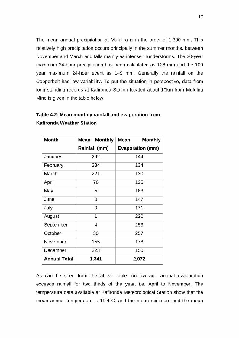
The mean annual precipitation at Mufulira is in the order of 1,300 mm. This
relatively high precipitation occurs principally in the summer months, between
November and March and falls mainly as intense thunderstorms. The 30-year
maximum 24-hour precipitation has been calculated as 126 mm and the 100
year maximum 24-hour event as 149 mm. Generally the rainfall on the
Copperbelt has low variability. To put the situation in perspective, data from
long standing records at Kafironda Station located about 10km from Mufulira
Mine is given in the table below
Table 4.2: Mean monthly rainfall and evaporation from Kafironda Weather Station
Month Mean Monthly Rainfall (mm)
Mean Monthly Evaporation (mm)
January 292 144
February 234 134
March 221 130
April 76 125
May 5 163
June 0 147
July 0 171
August 1 220
September 4 253
October 30 257
November 155 178
December 323 150
Annual Total 1,341 2,072
As can be seen from the above table, on average annual evaporation
exceeds rainfall for two thirds of the year, i.e. April to November. The
temperature data available at Kafironda Meteorological Station show that the
mean annual temperature is 19.4°C. and the mean minimum and the mean
Page 18
18
maximum temperatures are 11.3°C and 27.8°C respectively. The absolute
maximum temperature is 36.3°C and the absolute minimum temperature is
–3.8°C.
Incidences of Extreme Weather Conditions
Incidences of extreme weather conditions are rare. These include high winds
and floods.
4.3 Soils
The red lateritic soils of the Copperbelt generally have sandy top soils
overlaying a more loamy clayed subsoil. The soil profile is thickest over the
high ground and gradually thins towards the dambos and stream valleys.
These soils are susceptible to erosion by rainwater if soil conservation
practices are not used. Because of the high rainfall in the Copperbelt, the soils
are strongly leached, have a low reserve of plant nutrients and low base
saturation. The soils are acidic with pH ranging from 4.0 to 5.5 with no
discernable change in pH to a depth of about 3 m. Past studies findings are
summarized in table 3.3 below.
Table 4.3: Mufulira Soil Characteristics
Physical Characteristics
% Coarse % Fine
Sample Colour Texture % Clay %Silt Sand Sand pH
1 10YR 5/2 Clay Sand 5.6 6.7 76 11.7 4.9
2 10YR 7/6 Heavy Clay Sand 12.8 37.2 5 45 5.2
3 10YR 7/4 Clay Sand 10.2 9.9 21.7 58.2 5.1
Mendelsohn F (1961) divides the Mufulira sub region soils into three main
layers namely:
Page 19
19
(a) Upper Soil Layer
This layer is thickest (550 – 610 cm) over the Upper dolomite and the porous
quartzites and grits of the Footwall formation. Over the Mwashia and
Kundelungu shale this layer ranges from 0 to 305 cm, and over the Basement
it ranges from 370 to 460 cm in thickness.
In the Mufulira and Butondo stream valleys the upper soil has been removed
and the valleys are partly filled with alluvial clays and clayey soils. At the
edges of the stream dambos the upper soil becomes more clayey.
(b) Rubble Layer
This layer ranges in texture from a fine nodular aggregate of iron oxide
concretions to a coarse agglomeration of fragments of the underlying rock.
This layer is however, absent in the deeply incised Mufulira and Butondo
stream valleys.
(c) Lower Soil Layer
The lower soil under the rubble layer ranges in thickness from a few
centimeters over the more resistant Basement rocks and over quartzites and
shales, to more than 610cm over the Upper Roan dolomites. Partly
decomposed fragments of the underlying rock become more numerous at
depth and merge with the partly decomposed rock itself.
Pre-mining Land Use
There is no data on pre-mining land use activities. Industrial activities in the
general project area, has been on going since the 1930s.
Page 20
20
4.4 Natural Vegetation
The regional tree vegetation is predominantly of the Miombo woodland family
with elephant grass (Pennisetum purpureum) being the dominant grass type.
The surface area involved in the project is small, located within the plant site
boundaries and largely within the existing smelter complex.
4.5 Animal Life
There is little animal life in the project area vicinity presumably due to past
and ongoing mining activities, and human disturbance of the habitat. No rare
or endangered animals have been noted in the project vicinity, let alone in the
rest of the mine licence area.
4.6 Surface Water
Mufulira Mine licence area is principally drained by Mufulira, Luansobe,
Butondo, Mupambe and Kansuswa streams whose water eventually end up in
the Kafue river located about 15 km to the west of Mufulira Smelter. The
streams are located 1 km to 5 km from the project area. The streams and the
Kafue river are monitored regularly for impact of discharges from ongoing
mining activities. Wastewater leaving the Smelter complex acid plant will be
neutralized and discharged to the environment through the Concentrator
tailings disposal system.
4.7 Ground Water
Infiltration from precipitation into groundwater system has been estimated by
past studies at 7 to 10% of the average annual precipitation. Several of the
local streams cross outcrops of water bearing strata. However due to the
limited thickness of these strata, the recharge potential from the streams is
considered not substantial.
Page 21
21
Groundwater other than that from mine dewatering is monitored from a
number of boreholes that were sunk as part of the global EIS study in
2000/2001. The quality of the boreholes water has been consistently
acceptable when compared to wastewater limits. However boreholes located
outside the plant site boundaries have all but one located at the active tailings
dump, been vandalized by trespassers.
There are no known groundwater users in the Mine License Area or the
immediate surroundings. However a portion of mine dewatering water
pumped to surface is treated by another company and supplied to the
townships as potable water. The quality of this water is analysed by Mopani
analytical laboratory on a daily basis for pH and Total Dissolved solids, on a
weekly basis for pH, total hardness, suspended solids and total dissolved
solids and on a monthly basis for pH, Cl-, Cu, total hardness, Fe, Mn, Na, SO4,
total dissolved solids and Zn.
4.8 Air Quality
Significant air pollution at Mufulira results from gaseous emissions from the
Smelter. Other sources of air pollution but of lesser significance are bare
surfaces on the plant site and tailings dumps.
The project area i.e. the plant site has residential areas in its vicinity stretching
in a semi circular manner from the eastern through the southern to the
western side of the plant site, with some houses less than 500m from the
plant site fence. The residences most affected by plant site emissions are
those on the western side (Kankoyo Township), the prevailing wind direction.
However in the rain season when moist Congo air blows from the north-west
even the eastern parts of the town get affected by the plant site gaseous
emissions.
There will be no radioactive emissions.
Page 22
22
4.9 Noise
Noise generation will largely be localised to the plant site. Noise sources will
mainly be air blowers and fans. The work environment noise levels will be
significantly reduced as there will be no requirement for external cooling fans
(the major contributor to noise in the smelter) with the change to Isasmelt
technology. Significant but intermittent noise may arise due to increased traffic
of road trucks and trains bringing in foreign concentrates to the smelter and
transporting sulphuric acid and copper out of Mufulira.
4.10 Sites of Archaeological and Cultural Interest
There are no sites of archaeological and cultural interest in the area involved
in the project. Archaeological sites identified in the global study of the Mufulira
Mine licence area are far away from this project’s influence.
4.11 Sensitive Landscapes
There are no sensitive landscapes in the area of the project.
4.12 Visual Impacts The project area is located within the existing Mufulira plant site and has
therefore a visual aspect of an industrial area. Project components will be
located within the Mopani property and mostly inside the existing plant site
boundaries. New facilities which will be constructed to support this project will
therefore blend into the existing visual outlook without causing significant
change in the landscape. 4.13 Regional Social-Economic Structure The major activity on the Copperbelt is mining and majority of people in formal
employment work on the mines. A significant number of people are also
employed by local companies, that mainly deal in activities related to the
Page 23
23
mining industry, i.e. provision of equipment spares, labour hire and such other
support services. Those not employed by these businesses are mainly in
government ministries or its agencies or are in the informal sector of the
economy. The major activities in the informal sector are subsistence farming,
buying and selling of various goods and services and charcoal burning. The
driving force behind these informal economic activities is the mining industry’s
generated income.
The year 2000 census of population showed that unemployment for males
dramatically increased from 14% in 1990 to 24% in 2000, and this can be
attributed to the labour shocks brought about by the privatisation of the mining
industry, with the industry refocusing on the core business so as to quickly
return to profitability. The increase in unemployment may also have triggered
the observed net increase in migration of 6% from the region in the period
1990 to 2000.
There are a few commercial farmers on the Coppperbelt, mostly in cattle
ranching for beef and milk, crop farming (mainly maize), poultry and
horticultural. With the right type of investment and management agriculture
has potential for expansion in the region.
Mufulira Sub – region
The local economy is strongly supported by Mufulira mine of Mopani Copper
Mines Plc. Other economic sectors rely heavily on the mine for patronage. In
addition to the other industries that are supportive of mining activity, the
Mufulira Municipal Council represents another relatively major employer within
Mufulira. Informal economic activities are mainly subsistence farming,
charcoal burning and buying and selling.
At the last national population census carried out in 2000, the population of
Mufulira was estimated at 153,000 and the mining community households
accounted for about 14% of the district’s population. Mufulira district accounts
for about 9.6% of the Copperbelt’s province population. There will be no
Page 24
24
resettlement of people to pave way for project implementation. It is not
expected that project implementation will create an influx of new residents into
Mufulira, as the project is a relatively low labour operation and will largely
depend on the already existing idle labour force in the town.
An information sharing meeting on this project and the in situ leach project for
which approval has already been granted was held with community
representatives and issues raised in that meeting are detailed in appendix B.
4.14 Interested and Affected Parties
Other than relevant government departments and regulatory agencies, the
other key interested and affected parties are the following:
• Mufulira townships residents
• Mufulira local council
• Zambia Railways
• Mine Workers Union of Zambia
• ZCCM-IH
• Copperbelt Energy Corporation
• Local Religious and Political Organisations
• NGOs active in the district
• Local companies resident in Mufulira town
• Other copper mining companies in Zambia
5.0 MINE SITE CHARACTERIZATION 5.1 General
Mufulira mine is a mining complex comprising the underground mine, the
Smelter, the Concentrator, the Refinery and associated engineering and other
support facilities. The mine licence area covers 19,101 ha. Presently, the
major discharges into the environment are sulphur dioxide from the Smelter,
Page 25
25
waste rock from mining operations, tailings and effluent water from the
Concentrator. Mine dewatering water is largely used in the concentrator with a
portion supplied to AHC-MMS who process it into potable water. The major
existing environmental issue of concern is the continuing discharge of sulphur
dioxide from the smelter. Currently about 94,000 tonnes of sulphur dioxide is
vented annually from the smelter.
5.2 Concentrates Availability MCM production forecasts indicate a relatively consistent production of
approximately 400,000 tpa concentrate from MCM mines (Nkana and Mufulira
concentrators). Initially, this production would be supplemented by the
treatment of malachite sourced from the DRC and through purchase and toll
treatment of small quantities of concentrates from regional companies (i.e.
Chibuluma and KCM).
Discussion with Zambia’s mining industry management and Glencore trading
personnel indicated that by 2005, the potential quantity of concentrate
available for purchase or toll treatment in the immediate region would be
sufficient to fill the capacity of an 850,000 tpa concentrate smelter. The
companies included in Table 5.2 below currently export concentrates to
alternative smelters overseas or in South Africa, or require a smelting facility
to process concentrates after their mine / project development has been
completed.
Table: 5.2 Foreign Concentrates Requiring Smelting Facilities.
Company Operation Concentrates Tonnes/annum
Available from
Metorex Chibuluma
West / South 24,000 Present
Anvil Dikulushi 40,000 Present
J & W Baluba 78,000 mid-2004
Page 26
26
NFC Africa Chambishi 120,000 mid-2004
First Quantum Kansanshi 180,000 early 2005
Total 442,000
Although there is some uncertainty about the eventual project production
rates, at each of the above locations, there is a high degree of confidence that
there will be 250,000 tpa of concentrates available for treatment by 2006, and
this figure could well increase to around 500,000 tpa or more if potential
arisings from the north-western province of Zambia or the DRC are included.
Additionally, there remains the probability that concentrates will be made
available by KCM for purchase or toll treatment should KCM mine production
exceed the Nkana smelter capacity of 350,000 to 400,000 tpa concentrate.
After considering the projected availability of concentrate in the immediate
region and the existing cumulative smelting capacity of the Mufulira and
Nkana smelter, it is evident that the end of campaign of the existing electric
furnace represents a strategically valuable opportunity to install a smelter with
a capacity of 850,000 tpa which will initially be operated at 650,000 tpa.
5.3 Smelting Alternatives Considered
In evaluating the various smelting alternatives the following three points were
kept in focus:
(a) Increasing power costs in Zambia and recent global developments and
applications of more efficient high intensity smelting technology;
(b) Potential increase in concentrate availability above the 500,000 tpa level
from new mine developments in Zambia. 500,000 tpa is the maximum
throughput that commercially proven electric furnace technology has been
able to process adequately.
Page 27
27
(c) The legislation requirement for sulphur fixation at the Mufulira Ssmelter
and the disadvantages of low sulphur dioxide tenor from the electric furnace
process offgas.
Other than rebuilding the electric furnace to an increased capacity, other
smelting options were evaluated for installation at Mufulira as detailed below.
These alternatives were predominantly high intensity oxygen smelting
technologies, namely;
Outokumpu Flash Furnace Technology
Mitsubishi Continuous Smelting Process
Noranda/CMT Reactor Technology
KHD Contop Reactor Technology
Top Submerged Lance (TSL) Technology
Electric Furnace
Technology suppliers have advised that electric furnaces with capacity to treat
in excess of 500,000 tpa copper concentrate (the minimum treatment rate for
the Mufulira smelter) have not been constructed and as such constitute an
unacceptable high risk to MCM. Further treatment of the projected maximum
available concentrate tonnage of 850,000 tpa would require two parallel
electric furnaces, which based on the capital requirement for a single new
electric furnace would be an uneconomic option.
Outukumpu Flash Furnace Technology Outukumpu Flash Furnace technology is widely used throughout the world in
copper and nickel smelting applications. However, most recent applications
are in the first world countries where precision engineering capability and
extensive provision for technical support is readily available, e.g. Rio Tinto’s
Kennecott Utah Copper Corporation (KUCC) smelter in the USA and OKO /
Boliden’s Ronnskjear smelter in Sweden. This technology has a high capital
Page 28
28
requirement (e.g. US$880M for the complete KUCC smelting complex) and is
renowned for being difficult to commission to nameplate capacity within an
eighteen-month duration, the target for this upgrade project.
An alternative approach using flash smelting technology which was also
considered is direct-to-blister (DTB) flash smelting, utilising the high copper
content of the Mufulira concentrate to produce blister copper in a single
furnace. However, the current life-of-mine concentrate availability for the
Mufulira Smelter is not suitable for DTB smelting as the Mufulira Mine is
scheduled to exhaust reserves by 2014 and the replacement concentrates will
be low grade in respect to Mufulira concentrate and would result in high
reticulation of furnace slag through a flotation circuit to recover copper in slag.
As such, Flash Furnace technology was excluded on the basis of technical
complexity for the Zambian environment, not being well suited to the retrofit
nature of the Mufulira project and high capital requirement.
Mitsubishi Continuous Smelting Process The Mitsubishi Continuous Smelting process was first established in Japan
but has expanded to include commercial operations in Canada, Indonesia and
Australia, of which the latter has now closed. As with flash furnace
technology, the Mitsubishi process has a significant capital requirement and
engineering support services normally associated with western world
economies. Additionally, there is no commercial template for a Mitsubishi
system retrofit into a similar operation to Mufulira and as stated above, the
only integration of Mitsubishi technology into an existing `brownfield’ smelting
site (i.e. the Mitsubishi Converter at Port Kembla Copper, Australia) was not
successful.
The technology was therefore excluded on the basis of technical complexity
for the Zambian environment, not being well suited to the retrofit nature of the
Mufulira project and high capital requirement.
Page 29
29
Noranda / CMT Reactor Technology
The CMT horizontal reactor was initially developed at Codelco El Teniente
division and is widely accepted in Chile and more recently Mexico. The Nkana
smelter in Zambia has the only CMT reactor operating outside Latin America
and the operability of the Nkana smelter since the CMT was installed in 1994
has been problematic and not a basis for an endorsement of CMT reactor
development in Zambia. Noranda reactors, which are similar to CMT reactors,
were developed by Noranda in Canada and have had limited acceptance as
primary smelting technology with the exception of three operations in Chile,
Australia and China.
Both the CMT horizontal reactor and the Noranda reactor were excluded on
the basis of the poor performance of the CMT reactor in the Zambian
environment and the relatively inexperienced technical resources readily
available.
KHD Contop Reactor Technology
KHD Contop Reactor technology is a high intensity oxygen reactor that is
normally retrofitted to a reverberatory furnace. The technology is not widely
accepted and in operation it has not performed well, being shut down at
Palabora, South Africa and Asarco El Paso, USA. The technology has not
adequately proven itself and was therefore excluded.
Top Submerged Lance (TSL) Technology
Top Submerged Lance (TSL) technology was considered to be a viable
alternative to electric furnace smelting based on preliminary data and
marketing-level studies provided by two technology suppliers (Xstrata
Technology marketing the Isasmelt furnace and Ausmelt Technology
marketing the Ausmelt furnace).
Page 30
30
The TSL smelting process was first commercialised in Australia in the late
1980’s and has recently been gaining increasing acceptance in a wide range
of applications in such diverse countries as USA, Belgium, Germany, India,
China, South Korea, Peru, Malaysia, South Africa, Zimbabwe and Namibia.
The TSL smelting process relies on a vertical lance inside a vertical cylindrical
smelting vessel. The tip of the lance is submerged in the molten furnace
charge, and air, oxygen and/or fuel are injected via the lance, causing
extremely rapid smelting reactions. The advantages of the process include:
• compact size and small footprint, easily accommodated in a retrofit as
will be the case at Mufulira
• relatively low capital cost
• low operating costs, as much of the energy for smelting is provided by
the oxidation of sulphide minerals in the charge
• good containment of offgas, which is of high strength and well suited
for acid production
• relative ease of operation.
However, for optimum operation, TSL technology does require a supply of
tonnage oxygen, but this permits a considerable degree of flexibility, since the
furnace throughput can be increased over a substantial range by simply
increasing the degree of oxygen enrichment. TSL technology also requires
an auxiliary settling furnace because the TSL furnace bath is too small and
highly agitated to permit the effective separation of matte from slag.
After further consideration of the benefits MCM has decided to implement TSL
technology, specifically the Isasmelt furnace, for the Mufulira smelter and
construct a dedicated acid plant for fixation of sulphur dioxide produced by the
Isasmelt furnace.
Page 31
31
5.4 Support Facilities
Power supply
The combined power requirement for the new smelting and the associated
facilities (oxygen plant, acid plant, etc) will be approximately 31MVA. It is
envisaged that the power will be supplied from the existing Kankoyo and
Mufulira substations after being upgraded. Initially the Isasmelt furnace and
the existing electric furnace will be run in parallel. Once the Isasmelt furnace
is running at design capacity the existing electric furnace will be shutdown,
resulting in power requirements reducing to levels similar to the current
situation.
Water Supply
Process water will be obtained from that which is currently being pumped to
surface as mine dewatering. Domestic water will be tapped from existing plant
site system fed by AHC-MMS water treatment plant located within the mine
plant site boundaries.
Compressed Air
New air compressors will be installed to meet the requirements of the new
smelting equipment. There will be no impact on existing users.
Roads, railways, etc
The existing road and railway infrastructure will be used for transporting raw
materials and finished products.
Housing
No new housing units will be constructed. Workers will come from already
existing townships.
Page 32
32
Mine Disposal Sites Existing disposal sites for slag will be used. Acidic effluent will be neutralized
and disposed through the Concentrator tailings thickener.
Domestic and Industrial Waste Disposal sites Existing disposal sites will be used for the project. Disposal of hazardous
waste will be as per legislation and MCM procedure on waste management.
5.5 Alternatives to Stream/river Diversion
There will be no stream or river diversion
5.6 Final Products
The final products will be:
(a) Copper anodes, which will be sent to the Mufulira refinery for processing
into copper cathode which will be sold through the existing Mopani copper
market. Cathode copper production at the 650,000 tpa concentrate treatment
rate is expected to be 217,000 tpa.
(b) Sulphuric acid which will be partially used inhouse on various Mopani
operations (In situ and Heap leaching projects, Cobalt plant, Refinery, etc)
with the excess being sold to other users. Acid production will initially be at
298,000 tpa and will increase to 336,000 tpa at concentrate throughput of
850,000 tpa.
(c) Sulphur dioxide from the converters, which will be vented to the
atmosphere.
(d) Slag from the MSEF which will be discarded on existing slag dumps.
Page 33
33
5.7 Project Labour Force An additional 800 to 1,000 people will be employed during the construction
phase of the project in 2005. There will be no change in labour force strength
from the current smelter labour force of 570 employees during the operational
phase, as the reduced labour requirements for the Isasmelt furnace will be
offset by labour requirements for the acid and oxygen plants. However there
will be substantial retraining of the current labour force to meet the skills
demanded by the new plant facilities. A significant part of the training will take
place at comparable facilities in Australia and Philippines.
5.8 Project Expenditure
The capital cost of the project is expected to be approximately $110 million.
5.9 Land use post rehabilitation
Most likely not all infrastructure units will be demolished on cessation of
operations both for this project and those for currently ongoing activities.
Some facilities are likely to be sold or passed on to third parties for use post
mine life. Facilities like engineering workshops and office blocks fit into this
category of infrastructure with potential for being sold off. Facilities that will not
be of any economic or social value for the town of Mufulira will be demolished
and the sites rehabilitated to enhance the aesthetic appearance of the area.
6.0 PROJECT MOTIVATION The existing electric furnace is coming to the end of its campaign life cycle in
2005 and it is therefore necessary to either rebuild it or replace it with some
other type of a primary smelting vessel to guarantee continued copper
smelting at Mufulira Smelter. The continued use of an electric furnace (a
rebuild or a new expanded unit) will only be able to achieve a throughput of
500,000 tpa. However, Zambia’s copper industry management is projecting
copper concentrate availability beyond 2006 of 850,000 tpa.
Page 34
34
Electric furnace technology has not yet commercially developed to a level
where concentrates in excess of 500,000 tpa can be treated in a single
vessel. The installation of an Isasmelt furnace will provide MCM with the
flexibility to treat up to 850,000 tpa from the projected commissioning capacity
of 650,000 tpa for the primary smelting vessel.
Smelter operating cost are projected to drop from US$64 to US$54 and
US$51 per tonne of concentrate processed at 650,000tpa and 850,000tpa
throughputs respectively.
Further, the technology change will enable MCM to construct an acid plant for
fixation of in excess of 97% of the sulphur dioxide in the Isasmelt furnace
offgas. This translates into fixation of 55% to 59% of the total sulphur dioxide
to be produced by the new configuration at the smelter (at the 650,000 tpa
rate)
MCM will produce its own sulphuric acid at a much reduced cost when
compared to purchased acid. Currently MCM purchases acid for use at the
Nkana Cobalt Plant and Mufulira Refinery at a cost of US$155 per tonne. The
cost of producing acid at the new acid plant is estimated at US$25 per tonne
of acid.
Acid consumption within MCM is expected to increase from 100 tpd to 300 tpd
with the coming on line of the in situ leach and heap leach projects at Mufulira
and Nkana Mines respectively. Excess acid will be sold to other mines on the
Copperbelt and to new copper projects in the North-western province.
The fixation of sulphur dioxide produced by the Isasmelt furnace will set MCM
on a firm foundation, essential for eventually meeting its obligations to
complying with Zambia’s environmental legislation in respect of sulphur
dioxide and particulates emissions from the smelter. When compared to the
current scenario sulphur dioxide emissions will reduce by 18% at the initial
throughput of 650,000 tpa although the concentrate treatment rate will have
Page 35
35
gone up by 51%. Optimising the matte grade to 70% copper is expected to
reduce the emissions by 28% compared to the current operation.
There is potential to increase the sulphur dioxide capture level at a later stage
by expanding the acid plant to facilitate fixation of converters offgas. However
this is subject to a further evaluation of the sulphuric acid market and this
evaluation is scheduled for 2007/2008.
Implementation of this smelter upgrade project will create new employment
opportunities, preserve jobs in the smelter and also ensure MCM continued
positive contribution to economic activities at Mufulira in particular.
7.0 THE “NO PROJECT IMPLEMENTATION ” OPTION The no project implementation option in this case, means rebuilding the
electric furnace at the end of its campaign life in 2005 to current existing
operating parameters. This scenario would result in the following:
• MCM’s smelting process would not improve in respect of capacity,
efficiencies and environmental performance, parameters which MCM is
obliged to improve as per the Development Agreement.
• MCM would lose the opportunity to improve its bottom line through cost
reduction at the smelter and by producing its own acid for the heap
leach and in situ leach projects which are due to come on line during
2004. The cost of bought in acid is more than six (6) times the cost of
producing own acid. Acid cost will be the single major operating cost
for these two projects and will therefore determine the long-term
viability of these projects.
• The working capital requirements for rebuilding the existing electric
furnace would be extremely disadvantageous to MCM. Effectively,
MCM would not have a smelting capability for the five to six months
duration of the smelter rebuild during which time MCM would either
have to stockpile MCM concentrates (approximately 180,000 t) or
Page 36
36
transport concentrates for toll treatment at alternative international
smelting facilities.
• Temporary (during construction phase) and permanent jobs will be lost
due to non-implementation of this project.
• The potential to continue providing toll treatment facilities not only to
the Zambian copper industry, but to copper mines in the neighbouring
Congo DR may be lost due to constrained smelting capacity.
8.0 ENVIRONMENTAL ISSUES
The main environmental issue of concern in respect of this project is the
sulphur dioxide emissions. The current smelter operation discharges all
process offgas through the electric furnace stack and the converter stacks.
The project will include construction of an acid plant for the fixation of sulphur
dioxide produced by the Isasmelt furnace and thereby control overall sulphur
dioxide emissions to the atmosphere.
8.1 Land and Water Bodies which may be Affected The evaluation process for land and water bodies that may be affected was
based on the premise that an environmental exposure pathway normally
consists of four elements namely:
(a) A contamination source
(b) A retention or transport medium
(c) A point of potential contact with contaminated medium
(d) An exposure route at the point of contact
Land which may be significantly affected by the project operations is that on
which the project components will be located on and the slag disposal dump
sites.
Page 37
37
Project site groundwater may be affected by liquor seepage. The nearest
surface water source which may be affected, is the Mufulira stream to the
west of the project area. Site surface run off including storm drains
discharges eventually end up in the Mufulira stream.
8.2 Potential Significant Environmental Impacts due to Project Implementation and Operation Metallurgical Operations
(i) Air pollution due to venting of sulphur dioxide.
(ii) Air pollution due to dust carry over in gaseous emissions.
(iii) Dust from material stockpiles / storage sheds.
(iv) Noise due to construction and operation of project facilities.
(v) Surface water contamination by acidic spills and discharges into storm
drains.
(vi) Groundwater contamination by seepage from storage tanks areas
(vii) Human exposure to hazardous substances.
Other (i) Employment opportunities
(ii) Land use conflict
(iii) Water resources availability
(iv) Local /national economy
8.3 Environmental Mitigation and Monitoring programme Metallurgical Operations (i) Air pollution due to venting of sulphur dioxide
Compared to the existing scenario where all the sulphur dioxide produced is
vented, the project will allow for fixation of 55% to 59% of the total sulphur
Page 38
38
dioxide produced through the fixation of Isasmelt furnace offgas by the new
sulphuric acid plant. Only sulphur dioxide from the converters will be vented.
Fugitive sulphur dioxide emissions will be eliminated in the new Isasmelt
furnace and MSEF set up. The reduction in sulphur dioxide vented will be
18% when compared to the current operation. Optimising the matte grade
may further reduce sulphur emissions to 28% compared to the current
operation. On going sulphur dioxide monitoring on the plant site and in the residential
areas will continue. The meteorological station is being refurbished to facilitate
collection of weather information data for modelling of sulphur dioxide
dispersion.
(ii) Air pollution due to dust in gaseous emissions
The electrostatic precipitator and the evaporative cooler will capture dust
entrained in Isasmelt offgas for recycling to process. Any dust not captured in
the electrostatic precipitator will be collected in the acid plant gas cleaning
section (not emitted to atmosphere). Compared to the current situation there
will be a significant reduction in dust emissions. However the current stack
emissions dust monitoring will continue
(iii) Dust from material stockpiles / storage sheds
The concentrate shed with a nominal capacity of 30,000 tonnes will be fully
enclosed. Concentrates will be received in moist form with moisture content of
between 8 and 10% and will be offloaded through hopper offloading facilities,
with rail wagons using the tippler station and road trucks using a purpose built
offloading facility.
Coal for use will be purchased in pellet form (with sizes ranging from 6 mm to
38 mm) and will be used in this form to minimize potential for dust generation.
Page 39
39
The current on going monitoring of dust in the smelter will continue and will
include the new facilities.
(iv) Noise due to construction and operation of project facilities
Workers will be issued with appropriate personal protective equipment at all
stages of the project, and in addition the design and selecting of construction
materials will take into account use of materials with potential for noise
reduction during the operation phase.
(v) Surface water contamination by acidic spills and other discharges into
storm drains
All acid storage tanks will be in a bund wall enclosure. The enclosure will have
a capacity of 110% by volume that of the largest tank in the enclosure. Acid
pipelines will as far as is practical be above ground for early detection of leaks
and hence repairs and neutralization of leaked acid and disposal. Acidic
effluent generated by the process will be neutralized for disposal through the
concentrator tailings disposal system to the tailings dump.
An appropriate bund wall will be constructed at the acid-loading bay for spills
containment.
(vi) Groundwater contamination by acidic spills
Enclosures floors will be lined with impermeable material. The acid loading
bay floor will also be lined with impermeable material to prevent seepage of
acid into the ground.
One or two groundwater monitoring boreholes will be sunk in the vicinity of the
storage tanks and the loading bay.
Page 40
40
(vii) Human exposure to hazardous substances
A procedure incorporating storage, handling and transportation of sulphuric
acid will be developed. A similar procedure for the management of the
catalyst to be used in the acid plant will also be developed by taking into
account details contained in the substance material safety data sheets.
In respect of foreign concentrates supplied for treatment at the smelter, there
is an existing procedure used to screen the materials to ensure that they are
not radioactive. Materials showing above limit levels of radioactivity will not
be accepted for processing through the smelter.
Other (i) Employment opportunities
It is anticipated that an additional 800 to 1,000 people will be employed during
the construction phase of the project. With the exception of components of the
project where specialist skills will be required, most of the contract labour
requirement will be sourced within Mufulira. There will be no significant
increase in labour from the current 570 smelter employees during the
operation phase. However, certain employees within the smelter will be
retrained and redeployed to take up positions in operations of the new
facilities.
(ii) Land use conflict
There will be no land use conflict with the local community as the project
facilities will all be located within the existing plant site boundaries.
(iii) Water resource availability
The project water requirements will be met by water currently being pumped
to surface for dewatering the underground workings. The quantity, 110,000 m³
Page 41
41
per day of water is more than adequate to meet the needs of the whole mine
operations.
(iv) Local / national economy
The local economy is largely dependent on the mine for its sustenance and
patronage. This project will have a significant positive impact on the local
economy.
At the national level the mining industry still accounts for the bulk of the
country’s foreign exchange earnings. This project will provide an increased
capacity for treatment of not only MCM concentrates but also materials from
other operators within the Zambian mining industry. At full production it is
expected that the project will put in excess of 295,000 tonnes of cathode
copper on the international market and thereby significantly increase the
country’s foreign exchange earnings.
Page 42
42
REFERENCES Government of the Republic of Zambia;
- Statutory Instrument No. 29 of 1997, the Mines and Minerals
(Environmental) Regulations.
- Statutory Instrument No. 28 of 1997, the Environmental Impact
Assessment Regulations.
GRZ and MCM (2000); Development Agreement.
SRK CONSULTING (July 2003); MCM Mufulira EIS Volumes 1 & 2.