Mechanics of Solids (NME-302) Unit-V Unit-V Page 1 UNIT-V Curved Beams: Bending of beams with large initial curvature Position of neutral axis for rectangular, trapezoidal and circular cross sections Stress in Crane Hooks Stress in Circular Rings subjected to tension or compression. Unsymmetrical Bending: Properties of beam cross-section Slope of neutral axis, Stress and deflection in unsymmetrical bending, Determination of shear center and flexural axis (for symmetry about both axis and about one axis) for I-section and channel section.
Transcript
Mechanics of Solids (NME-302) Unit-V
Unit-V Page 1
UNIT-V Curved Beams:
Bending of beams with large initial curvature
Position of neutral axis for rectangular, trapezoidal and circular cross sections
Stress in Crane Hooks
Stress in Circular Rings subjected to tension or compression.
Unsymmetrical Bending:
Properties of beam cross-section
Slope of neutral axis,
Stress and deflection in unsymmetrical bending,
Determination of shear center and flexural axis (for symmetry about both axis and about one
axis) for I-section and channel section.
Mechanics of Solids (NME-302) Unit-V
Unit-V Page 2
Curved Beams Introduction:
Components with a large curvature are of engineering use in lifting machine and conveyor equipments.
Components such as crane hook, chains and links used for lifting machines are designed with safety
considerations. Therefore, determination of stresses in such components and location of critical sections are of
utmost importance.
The analysis of stresses in such components is quite complex. The theory of simple bending cannot be used for
such components because in simple bending, the component is considered as initially straight.
Stresses in a Curved Bar:
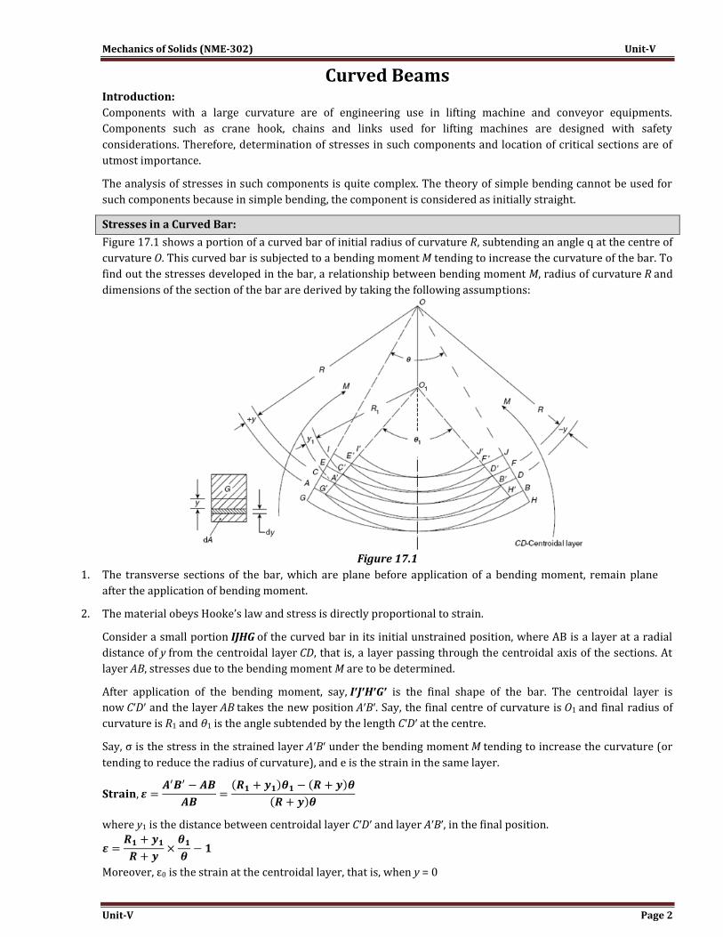
Figure 17.1 shows a portion of a curved bar of initial radius of curvature R, subtending an angle q at the centre of
curvature O. This curved bar is subjected to a bending moment M tending to increase the curvature of the bar. To
find out the stresses developed in the bar, a relationship between bending moment M, radius of curvature R and
dimensions of the section of the bar are derived by taking the following assumptions:
Figure 17.1
1. The transverse sections of the bar, which are plane before application of a bending moment, remain plane
after the application of bending moment.
2. The material obeys Hooke’s law and stress is directly proportional to strain.
Consider a small portion IJHG of the curved bar in its initial unstrained position, where AB is a layer at a radial
distance of y from the centroidal layer CD, that is, a layer passing through the centroidal axis of the sections. At
layer AB, stresses due to the bending moment M are to be determined.
After application of the bending moment, say, I′J′H′G′ is the final shape of the bar. The centroidal layer is
now C′D′ and the layer AB takes the new position A′B′. Say, the final centre of curvature is O1 and final radius of
curvature is R1 and θ1 is the angle subtended by the length C′D′ at the centre.
Say, σ is the stress in the strained layer A′B′ under the bending moment M tending to increase the curvature (or
tending to reduce the radius of curvature), and e is the strain in the same layer.
where y1 is the distance between centroidal layer C′D′ and layer A′B′, in the final position.
Moreover, ε0 is the strain at the centroidal layer, that is, when y = 0
Mechanics of Solids (NME-302) Unit-V
Unit-V Page 3
Dividing Eq. (17.1) by Eq. (17.2),
Now, y1 ≅ y considering that change in thickness is negligible.
Therefore,
The stress in the layer AB, which is tensile as is obvious from the diagram, that is, layers below the centroidal
layer are in tension and layers above the centroidal layer are in compression for the bending moment shown.
where E is the Young’s modulus of the material.
Total force on the section, F = ∫σ dA
Considering a small strip of elementary area dA, at a distance of y from the centroidal layer CD.
Now, the total resisting moment will be given by
Because ∫ ydA = 0, that is, first moment of any area about its centroidal layer is zero.
Therefore,
Let us assume that a quantity which depends upon the disposition of section and the radius of
curvature. Therefore,
From Eq. (17.4),
because the bar is in equilibrium and the net force on the section is zero as no force is applied, only moment is
applied. Now,
Mechanics of Solids (NME-302) Unit-V
Unit-V Page 4
Considering Eq. (17.4) again,
Substituting this value of in Eq. (17.5)
Substituting the value of ε0 in the equation for stress,
Substituting the value of ε0 again from Eq. (17.7),
On the other side of the centroidal layer y will be negative as for the layer EF shown in the figure.
σ′ = stress where y is negative
The expressions given in Eqs (17.8) and (17.9) are for the stresses due to the bending moment which tends to
increase the curvature. If the bending moment tends to straighten the bar or tends to decrease the curvature,
then θ1 < θ and R1 >R and the stresses will be reversed.
Bending Moment Tending To Decrease the Curvature:
For y to be positive (away from centre of curvature)
On the other side of the centroidal layer, where y is negative (towards centre of curvature)
Value of h2 for Sections made Up of Rectangular Strips:
Sections such as T, I and channel section are made up of rectangular strips, the value of h2 for each section can be
determined by considering each strip separately. For a single strip,
where B is the breadth, R2 is the radius at outer fibres and R1 is the radius of the inner fibres of the section from
the centre of curvature.
Mechanics of Solids (NME-302) Unit-V
Unit-V Page 5
Ring Subjected to a Diametrical Load:
Figure 17.17 shows a circular ring of mean radius R subjected to a diametric pull P. Consider a section CD at an
angle θ from the line of application of the load, that is, Y1Y2, and determine the bending moment and stresses in
this section. Due to symmetry, the ring can be divided into four equal quadrants. Say, M1 is the bending moment
on the section AB along the line of symmetry X1X2.
Taking moments about CD,
Bending moment at the section CD,
From Eq. (17.5)
where E is the Young’s modulus, ε0 is the strain in centroidal layer,
R is the initial radius of curvature and R1 is the radius of curvature after bending
Therefore,
Multiplying this equation throughout by Rdθ and integrating for one quadrant. That is,
However,
Now for one quadrant, initial angle θ = 90° = π/2 and final angle θ1 = 90° = π/2 due to symmetry, that is,
∠Y1OX1 remains 90° even after the application of diametral load. Therefore
Substituting this in Eq. (17.12), we get,
or,
Again by the Eq. (17.4)
Normal force on the section,
where
Therefore, normal force,
Figure 17.17
Mechanics of Solids (NME-302) Unit-V
Unit-V Page 6
Normal force on the section CD,
Substituting the value of ε0 in Eq. (17.13)
Now,
M will be maximum when θ = 0°.
M will be zero when
So, there will be four sections, one in each quadrant where the bending moment M will be zero and consequently
the stress due to bending moment will be zero. Now, substituting the value of M1 in the following equation.
and
Resultant stress at any point on the section
Mechanics of Solids (NME-302) Unit-V
Unit-V Page 7
Stress along Y1Y2axis, where θ = 0°
at the point K, y = d/2 where d = diameter of the rod of the ring
at the point J, y = - d/2
It can be observed that the maximum stress occurs at the point J, where the diametral load is applied.
Stresses along X1X2axis, where θ = 90°
At the point B, y = + d/2
At the point A, y = - d/2
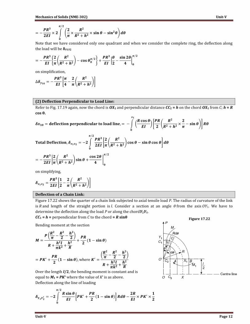
Chain Link Subjected to a Tensile Load:
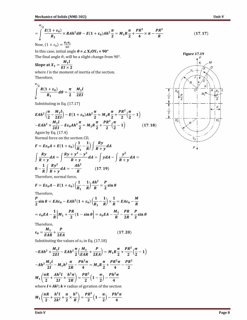
Figure 17.19 shows a chain link of mean radius R, length of the straight portion l, subjected to a pull P. Consider a
section CD at an angle θ from the line of application Y1Y2 of the pull P. Determine the bending moment and
stresses in this section. Due to symmetry, the ring can be divided into four equal parts as shown. Say, M1 is the
bending moment on the section AB along the line OX1.
Taking moments at the section CD,
From Eq. (17.5)
where E is the Young’s modulus, ε0 is the strain in the centroidal layer, R is the initial radius of curvature and R1 is
the final radius of curvature.
Therefore,
Multiplying throughout by Rdθ and integrating from 0 to π/2
Mechanics of Solids (NME-302) Unit-V
Unit-V Page 8
Now,
In this case, initial angle θ = ∠ X1OY1 = 90°
The final angle θ1 will be a slight change from 90°.
where I is the moment of inertia of the section.
Therefore,
Substituting in Eq. (17.17)
Again by Eq. (17.4)
Normal force on the section CD,
Therefore, normal force,
Therefore,
Therefore,
Substituting the values of ε0 in Eq. (17.18)
where I = Ak2; k = radius of gyration of the section
Figure 17.19
Mechanics of Solids (NME-302) Unit-V
Unit-V Page 9
Dividing throughout by π/2
However,
Substituting the value of M1 in Eq. (17.20)
Stress at any layer at a distance of y from the neutral layer is
Moreover,
Therefore,
Substituting the values of M and ε0, stress due to bending moment
Resultant stress, σR = σb + σd
This is an equation for resultant stress in any section along the curved portions X2Y1X1 and X2′Y2X1′ of the chain
link.
The bending moment M1 on the straight portion X1X1′ and X2X2′ will remain constant and for the straight portion
bending stress will be found with the help of general flexural formula. To obtain the resultant stress in this
straight portion, direct tensile stress P/2A will be added to the bending stress.
Mechanics of Solids (NME-302) Unit-V
Unit-V Page 10
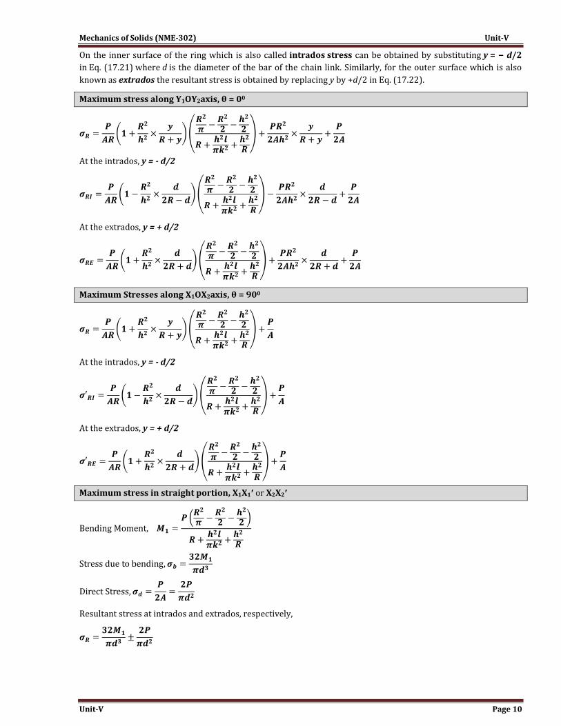
On the inner surface of the ring which is also called intrados stress can be obtained by substituting y = − d/2
in Eq. (17.21) where d is the diameter of the bar of the chain link. Similarly, for the outer surface which is also
known as extrados the resultant stress is obtained by replacing y by +d/2 in Eq. (17.22).
Maximum stress along Y1OY2axis, θ = 00
At the intrados, y = - d/2
At the extrados, y = + d/2
Maximum Stresses along X1OX2axis, θ = 900
At the intrados, y = - d/2
At the extrados, y = + d/2
Maximum stress in straight portion, X1X1′ or X2X2′
Resultant stress at intrados and extrados, respectively,
Mechanics of Solids (NME-302) Unit-V
Unit-V Page 11
Deflection of Curved Bar:
In order to estimate the stiffness of a curved beam, subjected to a bending moment. It is necessary to determine
the deflection of the curved beam and in such cases the influence of the initial curvature of the beam on its
deflection is considerable.
Figure 17.20 shows the centre line ABCD of a curved bar subjected to variable bending moment. Consider a small
portion BC of length ds along the centre line. Say, the bending moment at B is M and at C is M+ δM. Due to the
bending moment say the centre line of the curved beam takes new position ABF and the element BC rotates by an
angle dϕ = DBF at the point B. The angular rotation is small and the displacement of the point D is also small.
Displacement DF ≅ BD dϕ
∠ BDF = 90° for very small displacement DF
Components of the displacement are DE perpendicular to the chord AD and EF parallel to the chord AD, that is,
the line joining the ends of the centre line of the curved beam considered. FE shows negative displacement
towards the point A.
Deflection of the point D with respect to A is δDA and considering the small length ds only, say the deflection is
ΔδDA = −EF = −DF cos α where ∠DEF = α
= −(BD dϕ) cos α
∠ADF = α
Therefore, ∠BDG = 90° − α or ∠DBG = α
and BD cos α = BG
Therefore, ΔδDA = −(BD cas α)dϕ = − BG dϕ = −h dϕ
where h is the perpendicular distance of the point B
from the chord AD
Moreover,
Therefore,
Total deflection of D with respect to A
(1) Deflection of a Closed Ring:
Figure 17.21 shows the quadrant of a ring of mean radius of curvature R subjected to diametral pull P along OY1.
We have to determine the deflection along the load line or along the chord Y2Y1. (Point Y2 not shown in Fig.
17.19).
OY1 is half of the chord Y2Y1. Consider a small length ds at C at an angular displacement θ.
CC1 = perpendicular distance on chord from the point C = h = R sin θ