MOSFET MOSFET dosimetry in dosimetry in MOSFET MOSFET dosimetry in dosimetry in radiotherapy radiotherapy Joanna E.Cygler 1 and Paolo Scalchi 2 Joanna E.Cygler and Paolo Scalchi 1 Th Ott H it l R i l C C t Ott C d 1 The Ottawa Hospital Regional Cancer Centre, Ottawa, Canada 2 Department of Medical Physics, San Bortolo Hospital, Vicenza, Italy The Ottawa L ’Hopital The Ottawa L Hopital Hospital d’Ottawa Regional Cancer Centre
Transcript
MOSFET MOSFET dosimetry in dosimetry in MOSFET MOSFET dosimetry in dosimetry in radiotherapyradiotherapy
Joanna E.Cygler1 and Paolo Scalchi2Joanna E.Cygler and Paolo Scalchi
1Th Ott H it l R i l C C t Ott C d1The Ottawa Hospital Regional Cancer Centre, Ottawa, Canada
2Department of Medical Physics, San Bortolo Hospital, Vicenza, Italy
The Ottawa L’HopitalThe Ottawa L HopitalHospital d’OttawaRegional Cancer Centre
DisclosureDisclosureDisclosureDisclosure
The authors have received research support
from Thomson-Nielsen, Best Medical Canada
d Si l T h l i Iand Sicel Technologies, Inc.
Cygler, MOSFET dosimetry, AAPM Summer School 2009
OutlineOutline• Principles of MOSFET dosimetry• Brief description of commercially available MOSFET
systemssystems• Dosimetric characteristics of MOSFET detectors
– Temperature dependencep p– Energy dependence– Dose and dose rate dependence– Time dependence (other than the dose-rate dependence)Time dependence (other than the dose-rate dependence)– Angular dependence
• Advantages and disadvantages• Clinical dosimetry applications• Summary
Cygler, MOSFET dosimetry, AAPM Summer School 2009
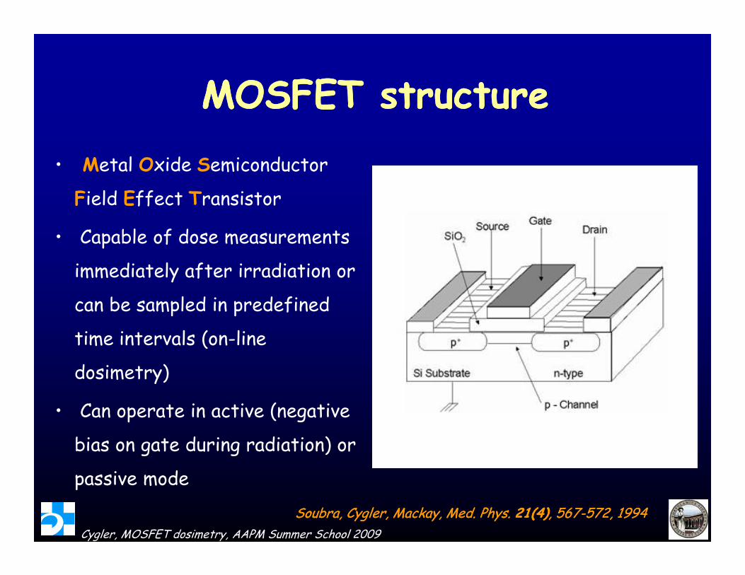
MOSFET structureMOSFET structureMOSFET structureMOSFET structure• Metal Oxide Semiconductor
Types of MOSFETs availableTypes of MOSFETs availableSingle bias, single MOSFET• Temperature dependenceTemperature dependence• Instability of responseDual-bias, dual-MOSFET
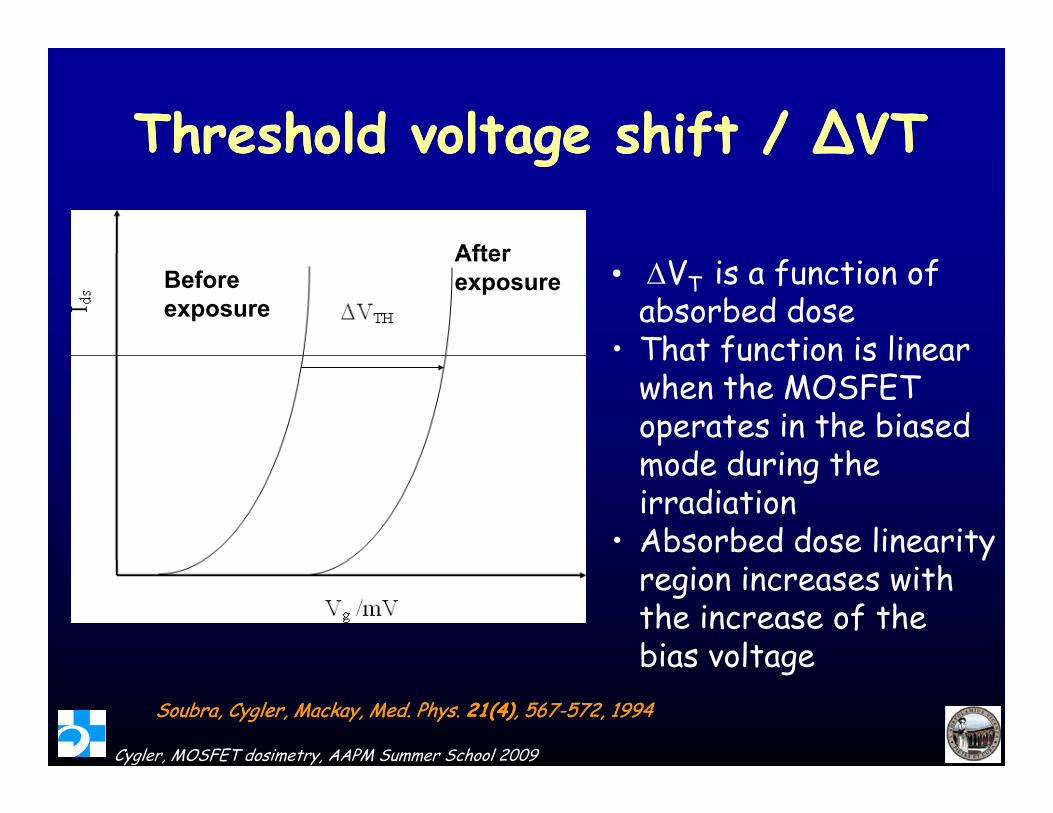
P d b S b C l t l i M d Ph (1994)• Proposed by Soubra, Cygler et. al. in Med. Phys. (1994)• Two MOSFETs on same silicon chip operating at two different
gate biases• Better sensitivity, reproducibility, and stability than single
MOSFET• Minimal temperature effectsUnbiased single MOSFET• Temperature dependence• Instability of response frequently used as disposable detectors
Cygler, MOSFET dosimetry, AAPM Summer School 2009
Instability of response, frequently used as disposable detectors• Shorter linearity range than biased MOSFETs
Nominal sensitivities in highNominal sensitivities in high--energy photon beams of various energy photon beams of various TN detector/bias combinations TN detector/bias combinations TN detector/bias combinations. TN detector/bias combinations.
Nominal sensitivityTN MOSFET type Bias Nominal sensitivity (mV/cGy)
Standard sensitivity Standard 1
Standard sensitivity High 3Sta da d se s t v ty g 3
High sensitivity Standard 3
Cygler, MOSFET dosimetry, AAPM Summer School 2009
High sensitivity High 9
OneDose MOSFET systemOneDose MOSFET systemOneDose MOSFET systemOneDose MOSFET system
• Electronics assembly Electronics assembly contains 2 MOSFETs and support circuitry
• Bi-directional antenna coil provides dosimeter power and communications channeland communications channel
• Hermetically sealed in bio-compatible glass capsule
MOSFETS
compat ble glass capsule
• Filled with medical grade epoxy
Cygler, MOSFET dosimetry, AAPM Summer School 2009
p y
CMRP MOSFET Dosimetry Systemy y
MOSkin detectors, thickness 0.07 mm, th ckness 0.07 mm, see Table 29-III
MOSFET Clinical Dosimetry System:
Cygler, MOSFET dosimetry, AAPM Summer School 2009
designed and distributed by CMRPCourtesy of Anatoly Rosenfeld
MOSFET calibrationMOSFET calibrationMOSFET calibrationMOSFET calibration• Purpose – to establish calibration coefficient of the p
detector
1),(
)()(0det
0
QDMQDQCF
)(1)(, QCF
QS wAD
Units: mV/cGyUnits: cGy/mV
kVQCFQD )()(
),(),( 00det QDVQDM
Cygler, MOSFET dosimetry, AAPM Summer School 2009
iith kVQCFQD )()(
Calibration processCalibration process
Calibration process dosimetric characterization of d lib i ffi i detectors calibration coefficient
• In principle, the users are responsible for the calibration of new detectors
• Some companies, e.g. Sicel sell pre-calibrated detectors.
– the user is still responsible for checking the calibration coefficients, so errors are avoided in patient dosimetry
Cygler, MOSFET dosimetry, AAPM Summer School 2009
Dosimetric characterization of Dosimetric characterization of MOSFET d t tMOSFET d t tMOSFET detectorsMOSFET detectors
• MOSFET detectors should be fully characterized before use
• How it is done, depends on the intended use of the detectorC lib ti i f ll b ild diti s• Calibration in full buildup conditions– in phantom, at a standard depth, e.g. dmax, 5 cm,
etcetc.– in a linac beam, simultaneous measurement of the
detector and ionization chamber signals
Cygler, MOSFET dosimetry, AAPM Summer School 2009
g
SSD calibration setSSD calibration set--upup
SSD1 = 80 cm (Co-60)
SSD2 = 100 cm (linac)Field Size = 10x10 cm2
SSD2 = 100 cm (linac)
MOSFET depth = 5.0 cm
Ion chamber Ion chamber depth = 11.3 cm Backscatter = 12.3 cm
Cygler, MOSFET dosimetry, AAPM Summer School 2009
*Diagrams not to scale
Clinical calibration processClinical calibration process• 50-100 MU delivered several times, threshold
voltage recorded before and after each trialg
• Simultaneous ion chamber measurement used to d t min th d s f h t i l)(QD
TG-51 PDD curves
determine the dose for each trial)(0 QD
Mraw Dose @ depth = 11.3 cm Dose to water at MOSFET location
TG 51 PDD curves
),()(
0
0
QDVQDCF
th
mVcGy
Cygler, MOSFET dosimetry, AAPM Summer School 2009
Calibration Process for DVSCalibration Process for DVS
• Calibration performed by the fmanufacturer
•The response (or radiation sensitivity) of each dosimeter is first determined using a
Sicel 60Co Irradiator
60Co source
• Calibration is performed in a Calibration is performed in a phantom (“in vitro” ) at body temperature (37°C) In Vitro Water Tank Testing
Cygler, MOSFET dosimetry, AAPM Summer School 2009
t mp ratur ( 7 ) In-Vitro Water Tank Testing
Courtesy of G. Beyer
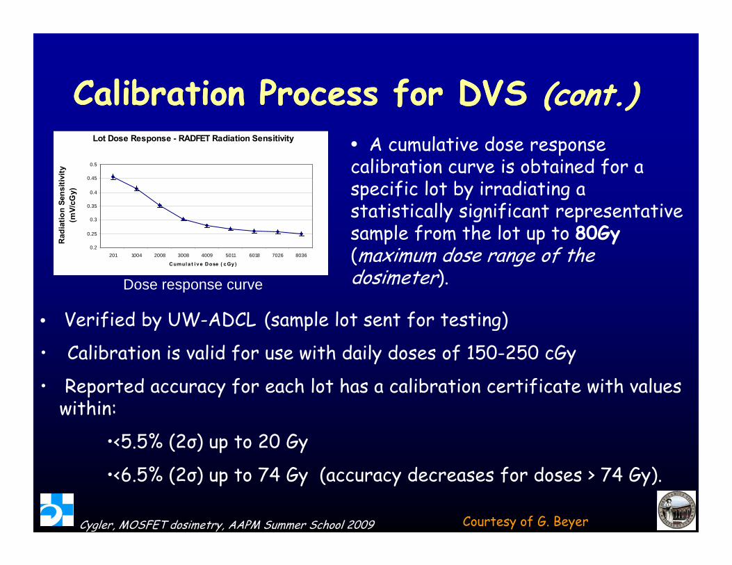
Calibration Process for DVS Calibration Process for DVS (cont.)(cont.)Calibration Process for DVS Calibration Process for DVS (cont.)(cont.)• A cumulative dose response calibration curve is obtained for a
Lot Dose Response - RADFET Radiation Sensitivity
0.5
vity
specific lot by irradiating a statistically significant representative sample from the lot up to 80Gy(0 2
0.25
0.3
0.35
0.4
0.45
Rad
iatio
n Se
nsiti
v(m
V/cG
y)
(maximum dose range of the dosimeter). Dose response curve
• Verified by UW ADCL (sample lot sent for testing)
0.2201 1004 2008 3008 4009 5011 6018 7026 8036
C umul a t i v e Dose ( c Gy )
• Verified by UW-ADCL (sample lot sent for testing)
• Calibration is valid for use with daily doses of 150-250 cGy
• Reported accuracy for each lot has a calibration certificate with values Reported accuracy for each lot has a calibration certificate with values within:
•<5.5% (2σ) up to 20 Gy
Cygler, MOSFET dosimetry, AAPM Summer School 2009
•<6.5% (2σ) up to 74 Gy (accuracy decreases for doses > 74 Gy).
Courtesy of G. Beyer
Correction factors for MOSFETsCorrection factors for MOSFETs
• Environmental – temperature (no pressure c cti n)correction)
• Energy dependence– beam energym gy– modality (photons, electrons, particles)
• Accumulated doseD • Dose rate
• Field size• SSDSSD• Directional dependence
Cygler, MOSFET dosimetry, AAPM Summer School 2009
Temperature dependenceTemperature dependenceTemperature dependenceTemperature dependence
• TN dual-MOSFET-dual-bias detector –temperature independentp p
• Other currently available MOSFET detectors Other currently available MOSFET detectors need corrections to be applied when used at a temperature different from the one at calibrationtemperature different from the one at calibration
Cygler, MOSFET dosimetry, AAPM Summer School 2009
Temperature dependenceTemperature dependence
The DVS is calibrated at 37oC 0.46
0.4723CThe DVS is calibrated at 37oC
for use at body temperature.
DVS dosimeter is 0.42
0.43
0.44
0.45
0.46
nsiti
vity
(mV
/cG
y) 37CLinear (23C)
DVS dosimeter is approximately 3.3% more sensitive (higher dosereading for same applied dose)
y = -1.0054E-02x + 4.5635E-010.38
0.39
0.40
0.41
Aver
age
sen
g pp )when irradiated at 37oC vs. 23oC
0.370 1 2 3 4 5 6 7 8
Irradiation session #
A multiplicative correction factor of 1.033 can be used for room temperature phantom measurements
Cygler, MOSFET dosimetry, AAPM Summer School 2009
Courtesy of G. Beyer
MOSFET energy dependenceMOSFET energy dependenceMOSFET energy dependenceMOSFET energy dependence
Edwards et al 1997
Wang et al MC
Wang et al, MC, 2005
Air-kerma sensitivity
Wang et al MC 2005Kron et al 1998
Kron et al, 1998
Edwards et al, 1975
Air-kerma sensitivity
Kron et al, 1998
Absorbed dose ensitivity
photon energy / keV
Cygler, MOSFET dosimetry, AAPM Summer School 2009Wang et al Radiat. Prot. Dos. 2005
p gy
MOSFET energy dependenceMOSFET energy dependenceTNTN 502 RDM502 RDMTNTN--502 RDM502 RDM
1.09
)
1.05
1.07
cGy/
mV)
1 01
1.03
Fact
or (c
0.99
1.01
brat
ion
0.95
0.97
Cal
i
Cygler, MOSFET dosimetry, AAPM Summer School 2009
C0-60 4 MV 6 MV
Beam Energy Courtesy of T. Woods
Energy dependence Energy dependence -- TNTN--502502--RDRD
* experiment* experiment MC high energy X-rays
● MC mono-energetic beams
Cygler, MOSFET dosimetry, AAPM Summer School 2009
Panettieri et al Phys Med Biol. 52(1):303-16.2007
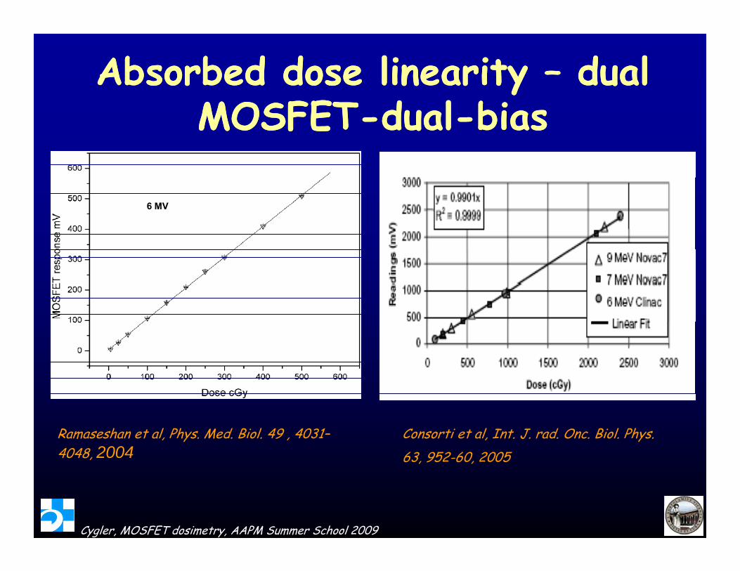
Absorbed dose linearity Absorbed dose linearity –– dual dual MOSFETMOSFET d ld l bibiMOSFETMOSFET--dualdual--biasbias
6 MV
Consorti et al, Int. J. rad. Onc. Biol. Phys.63, 952-60, 2005
Ramaseshan et al, Phys. Med. Biol. 49 , 4031–4048, 2004
Cygler, MOSFET dosimetry, AAPM Summer School 2009
Effect of accumulated doseEffect of accumulated doseEffect of accumulated doseEffect of accumulated dose
Ramani et al Int. J. Rad. Onc. Biol. Ramani et al, Int. J. Rad. Onc. Biol. Phys., 37, 959-64, 1997
Cygler, MOSFET dosimetry, AAPM Summer School 2009
Effect of accumulated dose Effect of accumulated dose ––Eff f mEff f munbiased MOSFET unbiased MOSFET -- DVSDVS
Example of a spherical phantom that can be used to pmeasure angular dependence of MOSFET response
Cygler, MOSFET dosimetry, AAPM Summer School 2009
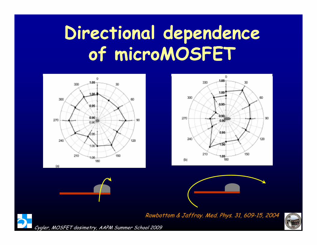
Directional dependence
Energy: 100 kVp , FS:10x10 cm2 ,FSD:50 cm, Depth:1.5 cm
1.05
1.10
onseXray Tube
0.90
0.95
1.00
ativ
e re
spo
Rotating insert
0.80
0.85
0 30 60 90 120 150 180 210 240 270 300 330R
ela
3 cm
Polystyrene phantom Angle / deg(25 cm x 25 cm x 3 cm )
Isotropic within 2.5% (1SD) Cygler et al, Radiother. Onc. 80, 296–301, 2006
Cygler, MOSFET dosimetry, AAPM Summer School 2009
Time dependence Time dependence -- CyberknifeCyberknifeTime dependence Time dependence CyberknifeCyberknife•• Cyberknife: long treatment timesCyberknife: long treatment times
•• HighHigh--dose DVS dosimeter initial design dose DVS dosimeter initial design --significant dependence of response on irradiation significant dependence of response on irradiation g p pg p ptime: 1time: 1--h and 2.5h and 2.5--h multiple irradiations caused h multiple irradiations caused mean overmean over--responses of 4% and 8%, respectively, responses of 4% and 8%, respectively, when compared to a single irradiation of when compared to a single irradiation of 1.5 min.1.5 min.
•• Improved DVS design Improved DVS design -- no time dependence no time dependence p gp g pp(response within 2 %)(response within 2 %)
Cygler, MOSFET dosimetry, AAPM Summer School 2009
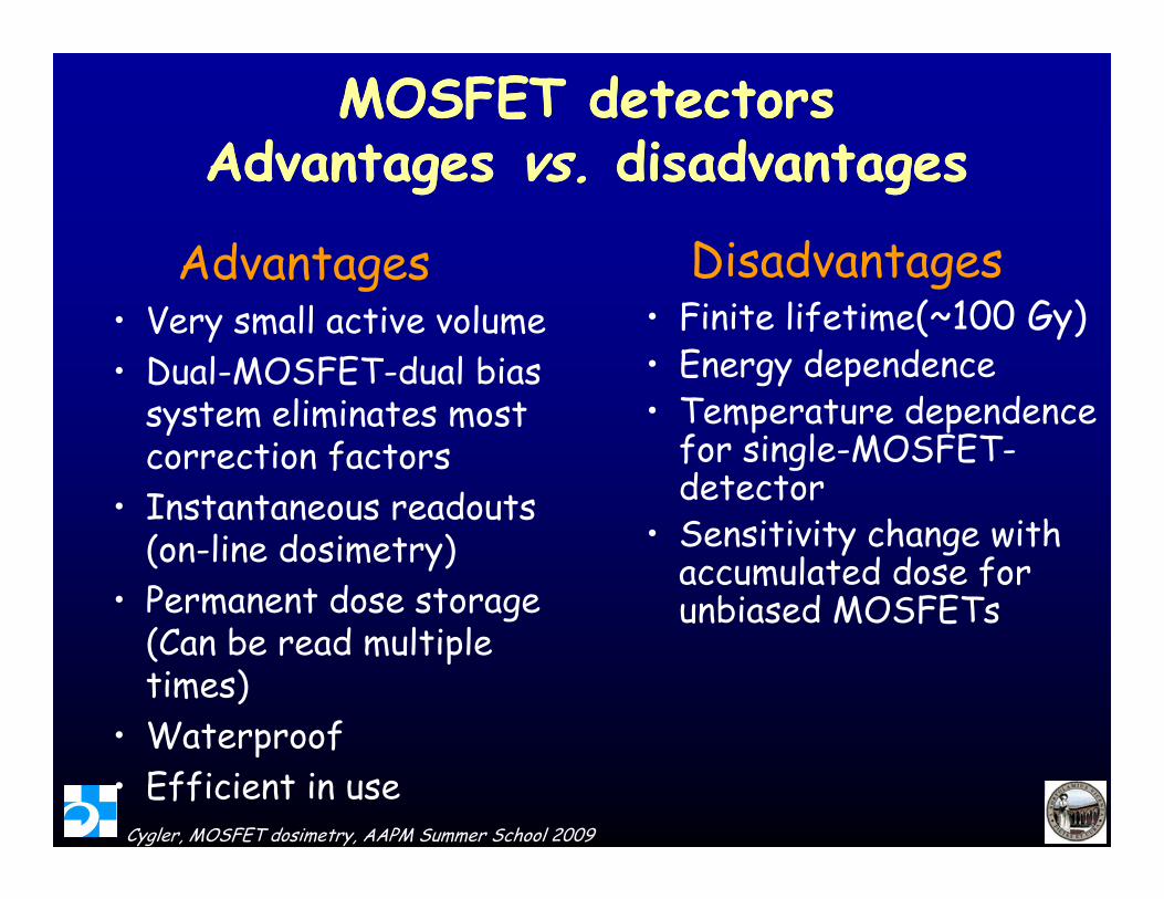
MOSFET detectorsMOSFET detectorsAdvantages Advantages vs vs disadvantagesdisadvantagesAdvantages Advantages vs. vs. disadvantagesdisadvantages
Advantages Disadvantagesdvantages• Very small active volume • Dual-MOSFET-dual bias
g• Finite lifetime(~100 Gy)• Energy dependence
system eliminates most correction factors
• Instantaneous readouts
• Temperature dependence for single-MOSFET-detector• Instantaneous readouts
(on-line dosimetry)• Permanent dose storage
• Sensitivity change with accumulated dose for unbiased MOSFETsg
MOSkin chip developed at CMRP allows measurements allows measurements of the surface dose at a depth of 0.07mm
Cygler, MOSFET dosimetry, AAPM Summer School 2009Courtesy of Anatoly Rosenfeld
Entrance and exit dosimetryEntrance and exit dosimetryEntrance and exit dosimetryEntrance and exit dosimetry
• Use of build-up caps is recommendedp p
• OneDose Plus detectors – come equipped with caps
• TN MOSFETs – one can fit inside special buildup
capscaps
Cygler, MOSFET dosimetry, AAPM Summer School 2009
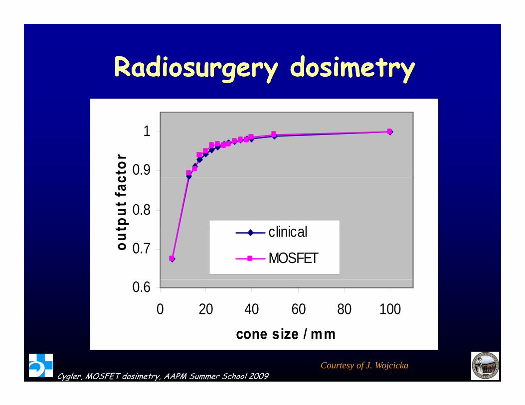
Radiosurgery dosimetryRadiosurgery dosimetry
1
Radiosurgery dosimetryRadiosurgery dosimetry
0.9
1ct
or
0.8
tput
fac
li i l0.7ou
t clinical
MOSFET
0.60 20 40 60 80 100
i /
Cygler, MOSFET dosimetry, AAPM Summer School 2009
cone size / mm
Courtesy of J. Wojcicka
IMRT in vivo dosimetryIMRT in vivo dosimetryyy
Marcie et al, Int. J. Rad. Onc. Biol. Phys., 61, 1603–6, 2005 • In some cases BB’s placed on top
Cygler, MOSFET dosimetry, AAPM Summer School 2009
In some cases, BB s placed on top of patient’s mask for original CT
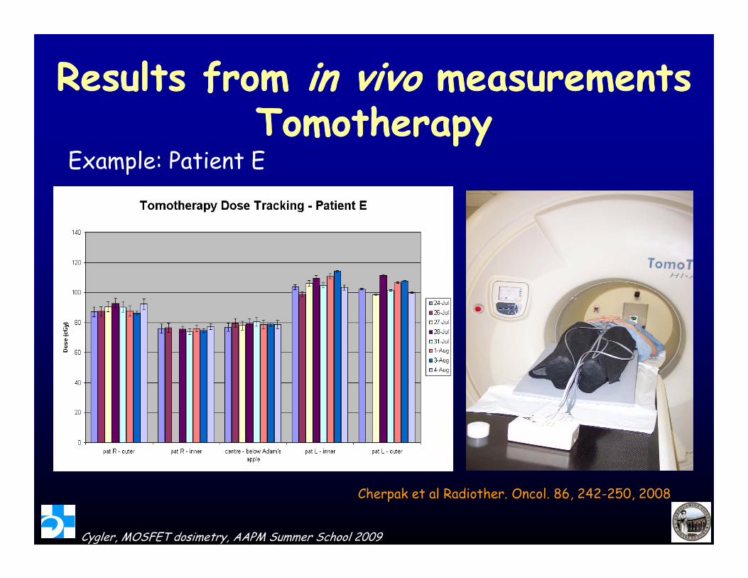
Results from Results from in vivoin vivo measurementsmeasurementshhTomotherapyTomotherapy
Example: Patient E
Cygler, MOSFET dosimetry, AAPM Summer School 2009
Cherpak et al Radiother. Oncol. 86, 242-250, 2008
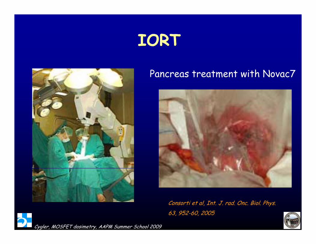
IORTIORTIORTIORT
Pancreas treatment with Novac7Pancreas treatment with Novac7
Cygler, MOSFET dosimetry, AAPM Summer School 2009
Consorti et al, Int. J. rad. Onc. Biol. Phys.63, 952-60, 2005
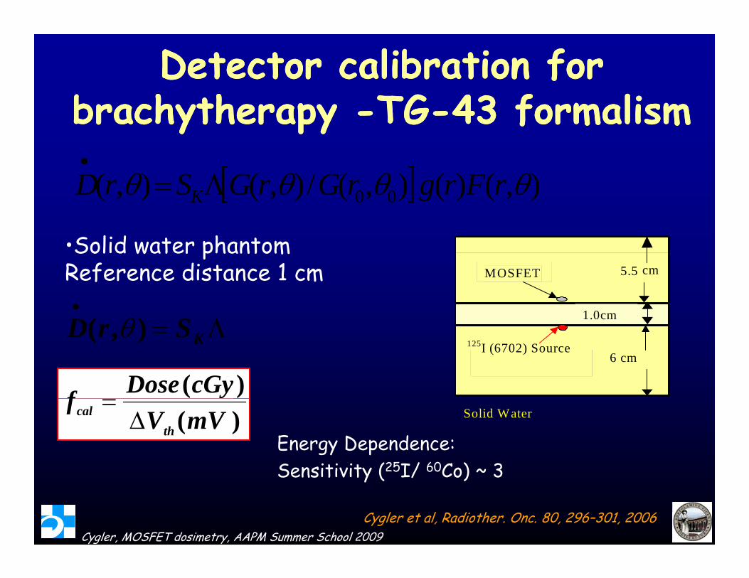
Detector calibration for Detector calibration for brachytherapy brachytherapy TGTG 43 formalism43 formalismbrachytherapy brachytherapy --TGTG--43 formalism43 formalism
)()()(/)()( FGGSD
•Solid water phantom
),()(),(/),(),( 00 rFrgrGrGSrD K
5.5 cm
1.0cm
MOSFET
Solid water phantom Reference distance 1 cm
SrD )( 6 cm
125I (6702) Source KSrD ),(
)(cGyDosefSolid Water )(mVV
fth
cal
Energy Dependence:Sensitivity (25I/ 60Co) ~ 3
Cygler, MOSFET dosimetry, AAPM Summer School 2009
Sensitivity (25I/ 60Co) ~ 3
Cygler et al, Radiother. Onc. 80, 296–301, 2006
In VivoIn Vivo Measurements Measurements –– prostate prostate 7
implantsimplants
SetscrewSetscrew
seed
1
US probe
12
34
US probe
MOSFETMOSFETMOSFET positionMOSFET position
Cygler, MOSFET dosimetry, AAPM Summer School 2009
Fluoroscopy image of the prostate after implant
••MOSFET reading taken every 1cm MOSFET reading taken every 1cm
Use of MOSFET detectors during Use of MOSFET detectors during i l d i l dprostate implant procedureprostate implant procedure
l l t d i iti l l () d t i l t ( )
10
12
/h)
150% mPD
calculated initial pre-plan () measured post implant ()
6
8
Rat
e (c
Gy/
90% mPD
mPD
2
4
Initi
al D
ose
Prostate length = 50 mm
Prostate Base
Prostate Apex
90% mPD
0
2
0 10 20 30 40 50 60 70 80 90 100 110Distance (mm)
g
Cygler, MOSFET dosimetry, AAPM Summer School 2009
Cygler et al Radiotherapy and Oncology 80: 296-301; 2006
Distance (mm)
BNCT at BNL medical research BNCT at BNL medical research ttreactorreactor
0.80
1.00
dose
0.20
0.40
0.60
elat
ive
boro
n
0.00
0.20
0 2 4 6 8 10 12Depth in phantom (cm)
Re
Thermal neutron depth dose distribution in a perspex phantom in a BNCT epithermal neutron beam facility at BNL obtained with paired MOSFET detectors with 10B converter Subtracting on line
Cygler, MOSFET dosimetry, AAPM Summer School 2009
paired MOSFET detectors with 10B converter. Subtracting on-line the response of paired MOSFET eliminate effect of gamma dose.
Courtesy of Anatoly Rosenfeld
ConclusionsConclusionsConclusionsConclusions
• MOSFET detectors are very useful for dosimetry • MOSFET detectors are very useful for dosimetry,
especially
– High dose gradient fields
• Accurate if properly characterized and usedAccurate if properly characterized and used
• Phantom (in vitro) dosimetry
• In vivo dosimetry in external beam and brachytherapy