Hindawi Publishing CorporationModelling and Simulation in EngineeringVolume 2007, Article ID 50586, 6 pagesdoi:10.1155/2007/50586
Research ArticleMotion Control and Implementation foran AC Servomotor System
L. Canan Dulger and Ali Kirecci
Received 4 September 2006; Revised 5 January 2007; Accepted 17 January 2007
Recommended by Igor Kotenko
This paper presents a study on trajectory tracking problem for an AC synchronous servomotor. A mathematical model for thesystem including AC synchronous servomotor, gearbox, and a load is developed to examine the systems dynamic behavior. Thesystem is controlled by a traditional PID (proportional + integral + derivative) controller. The required values for the controllersettings are found experimentally. Different motion profiles are designed, and trapezoidal ones are implemented. Thus, the exper-imental validation of the model is achieved using the experimental setup. The simulation and experimental results are presented.The tracking performance of an AC servomotor system is illustrated with proposed PID controller.
Electric motors can be classified by their functions as servo-motors, gear motors, and so forth, and by their electrical con-figurations as DC (direct current) and AC (alternating cur-rent) motors. A further classification can be made as singlephase and polyphase with synchronous and induction mo-tors in terms of their operating principles for AC motors, andPM (permanent magnet) and shunt DC motors for DC’s. Al-though DC motors are preferred dominantly in the variablespeed applications, increasing use of AC motors can be seenprior to improvements in solid state components. Servomo-tor is a motor used for position or speed control in closed-loop control systems. The requirement from a servomotor isto turn over a wide range of speeds and also to perform po-sition and speed instructions given. DC and AC servomotorsare seen in applications by considering their machine struc-ture in general. When the requirement is low power and vari-able speed, AC servomotors are the ones preferred in controlsystems. They certainly introduce a brushless structure andoffer no maintenance [1–4]. Applications of AC servomotorscan be seen in conveying technology, printing, wood process-ing, textile industry, plastics industry, food and packaging in-dustry, packaging and filling plants, and machine tools. Twotypes of AC servomotors are available as squirrel cage asyn-chronous and permanent magnet synchronous.
In the field of control of mechanical linkages and robots,research works are mostly found on DC motors. Limited
number of studies are found in the literature about AC ser-vomotor motion control and tracking characteristics, sinceAC servomotor technology is respectively new. AC servomo-tors applied in some research articles are overviewed herein.Gross [5] has described a study on simulation and dynamicperformances of electrical machines; the transformer, the DCmachine, the polyphase induction machine, the polyphasesynchronous machine, and the single phase induction ma-chine with an electric machine simulation program. Viita-nen et al. [6] in his work presented an environment to modeland simulate mechatronical devices; electrical motors (ACand DC), electronics, fluid power and control, and mechan-ical systems. Morimoto et al. [7] have described a study ona high-performance servo drive system and characteristics ofa salient pole permanent magnet motor. Lessmeier et al. [8]compared the performances of AC servo drives using syn-chronous and asynchronous motors. A mathematical modelis given with the control scheme and supported by experi-mental results. Tzou [9] achieved robust control of an AC in-duction servomotor for a motion-control system. Friedrichand Kant [10] have given a comparative study between twopermanent magnet AC machines by using numerical simula-tion and also experimentally. Simulations were included fora two-joint rigid robot directly driven by induction motors.Jiang and Holtz [11] have worked on high dynamic speedsensorless AC drives. Experimental verification was achievedwith an induction motor. On-line mode parameter tuningwas applied to eliminate the steady-state error. Vukosavic and
2 Modelling and Simulation in Engineering
Stojic [12] have dealt with the problem of mechanical reso-nance in a system of comprising a permanent magnet syn-chronous servomotor and a load with experimental verifi-cation. Goldfarb and Sirithanapipat [13] have given a studyon the performance of PD controlled servo systems. Simu-lations were carried on the measure of tracking. Safak andTurkay [14] studied universal motor dynamics. A mathemat-ical model was presented with simulation results. An exper-imental implementation was included. In a motion controland implementation, Guerrero-Ramırez and Tang [15] per-formed motion control of robots by induction motors totrack the given trajectory by proposing a current controller.Wang et al. [16] developed a complete PM AC servomotormodel. A neural network self-tuning PI control scheme isimplemented. Experimental results are presented with sim-ulations in that study.
This paper discusses dynamic behavior and practical im-plementation on AC synchronous servomotor. A permanentmagnet synchronous AC servomotor with a fitted resolveris applied in this study. Resolver is considered as a rotarytransformer producing an output signal which is a functionof the rotor position. Mathematical model of the system isdeveloped by including motor, gearbox, and an inertia diskrepresenting the load. An experimental arrangement is builtup, and characteristically different motion profiles are im-plemented to examine the positioning performance of thesystem for potential industrial applications. AC synchronousservomotor is incorporated with a PID controller. Simula-tion model and experimental results are presented herein toform a base for similar studies. The study is verified experi-mentally.
2. EXPERIMENTAL SYSTEM
The experimental system consists of a 1.5 kW permanentmagnet synchronous AC servomotor fed from an inverteroperated at 190 Hz frequency and its matching servo drive,a gearbox with 5.665 : 1 reduction ratio, a fitted resolver,and a constant load. The experimental verification is per-formed using the setup. The hardware configuration of theexperimental AC servomotor system is presented in Figure 1.Motor-driver data is given in Table 1.
A motion-control card [18] manufactured by Perfor-mance Motion Devices Inc. (PMD-MC) 1401 series DB1000PC motion-control card is chosen as an interface. The con-trol card provides a 4-axis control with incremental quadra-ture encoder input. The software needed is provided by themanufacturing company. Motor-control system configura-tion is achieved by using a 68-pin connector to dual 34-pinheader converter cable.
3. AC SERVOMOTOR DYNAMICS
The model of the system consists of a motor coupled to agearbox and an inertial load rigidly fixed to output shaft.Friction is taken as negligible throughout the analysis. Therelations for stator and rotor windings and dynamic torqueanalysis for the permanent magnet AC synchronous machinecan be described by the following nonlinear differential equa-
MDSKS 056-23
AC servomotor Gearbox
Load
Resolver cablePower cable
(S9322) (MC1401series)
PC
Servo drive Motion-control card
Figure 1: Configuration of system hardware.
Table 1: AC servomotor-driver data [17].
Drive type-9322
Motor power P = 0.75 kW
Motor output current, 8 kHz I = 2.5 A
Output power P = 1.7 kVA
Terminal voltage V = 320–528 V
Weight m = 3.5 kg
Motor type-MDSKS 056-23, 190
Motor weight m = 5.3 kg
Speed n = 3800 rpm
Torque T = 2.8 Nm
Power P = 1.1 kW
Voltage V = 330 V
Current I = 2.3 A
Maximum torque Tmax = 11.6 Nm
Maximum current Imax = 10 A
Frequency f = 190 Hz
Moment of inertia Jm = 1.2 kg · cm2
tions [7, 19, 20]:
RRIR + LRdIRdt
+ Lod
dt
(Ise
− jθm) = VR, (1)
RsIs + LsdIsdt
+ Lod
dt
(IRe
jθm) = Vs, (2)
(Jm + Jg +
1N2
Jl
)d2θmdt2
+ cdθmdt
= K1Vs − K2dθmdt
. (3)
The following symbols are used in the above equations:
(i) RS, RR: stator and rotor resistances (Ω),(ii) LS, LR, Lo: stator, rotor, and mutual inductances (mH),
(iii) K1, K2: motor constants (Nm/V, Nms/rad),(iv) Vs: control field voltage in stator,(v) c: damping resistance of the load (Nms/rad),
(vi) θm: angular position of the motor (rad),(vii) θmR: reference angular position of the motor (rad),
(viii) θm: angular velocity of the motor (rad/s),(ix) θm: angular acceleration of the motor (rad/s2),
L. C. Dulger and A. Kirecci 3
(x) Jm, Jg , Jl: moment of inertias of the motor, gearbox,and load,
(xi) N : reduction ratio between motor and load (5.666 : 1),
and K1 and K2 are calculated from the following relation-ships:
(i) K1 = stall torque/rated voltage (Nm/V),(ii) K2 = stall torque/no-load speed at rated voltage
(Nms/rad).
3.1. Controller settings
Three-mode control referred to PID (proportianal + inte-gral + derivative) control is incorporated with the systemto eliminate tracking errors. The PID tuning parameters arefound by applying Ziegler-Nichols (ZN) amplitude decay re-sponse of the closed-loop system with proportional gain.The gain is increased until the system becomes critically sta-ble. Kcr corresponds to this gain. Then the period of oscil-lation is taken as Tcr. So controller tuning is performed byexperimental settings of the three parameters for PID con-troller [2, 4, 21]. PID tuning parameters are calculated asKp = 0.6Kcr, Ti = 0.5Tcr, and Td = 0.12Tcr. Several itera-tions are required in the model to obtain the desired systembehavior.
PID controller is described as
Vs = Kpe(t) + Kvd
dte(t) + Ki
∫ t
0e(t)dt, (4)
where Kp, Kv, and Ki represent the proportional, derivative,and integral gains, respectively.
In the equation, gains are referred to as Kv = KpTd andKi = Kp/Ti. e(t) is the error given by
e(t) = θmR − θm (5)
and Vs in (2) is the PID controller output.
3.2. Simulation results
The performance characteristics of AC servomotor controlsystem is studied initially by using test input signals likestep and ramp input. Having obtained critically damped re-sponses, motion profiles involving trapezoidal character arethen implemented.
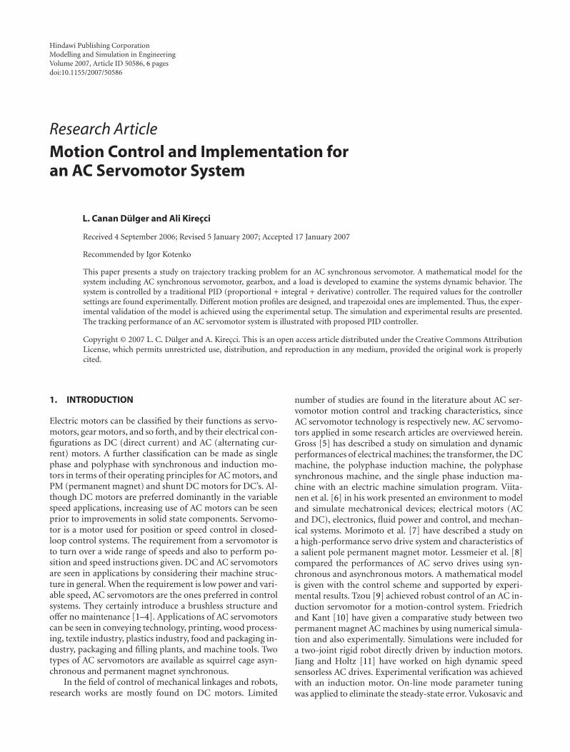
Two trapezoidal motion profiles called as trapezoidalmotion I and II are applied. Trapezoidal profile I has an initialconstant velocity period followed by a dwell period and thenfollowed by a constant velocity period in reverse direction asshown in Figure 2(a). This is an easy profile to implement asa reference motion. Here, trapezoidal profile I consisting of3 segments is performed in 4.16 seconds. Initially motor is
43210
Time (s)
0
1
2
3
4
5
6
7
An
gula
rdi
spla
cem
ent
(rad
)
ReferenceSimulation
(a)
43210
Time (s)−8
−4
0
4
8
An
gula
rve
loci
ty(r
ad/s
)
ReferenceSimulation
(b)
Figure 2: Simulation results for trapezoidal motion I.
rotated to 2π radians in 1.1 seconds, kept its angular posi-tion the same for 1.95 seconds, finally, slowed down to zeroradians in 1.1 seconds.
Trapezoidal profile II has an initial constant velocity fol-lowed by a dwell, a higher constant velocity followed by an-other dwell, a higher constant velocity with a longer dwellperiod, and finally at the highest constant velocity of all inreverse direction as shown in Figure 3(a). Trapezoidal pro-file II involving 7 segments is performed in 6.8 seconds inthis study. Servomotor is rotated to 2π radians in 1 second,kept its position the same (dwell) for 1 second, increasedto 4π radians in 0.5 second, kept at 4π radians (dwell) forsome time as 1.5 seconds, later increased to 6π radians to 0.4second, kept the same angular position (dwell) for 1.6 sec-onds, and finally decreased its position to zero radians in 0.8second.
The computer simulation employs a fourth order Runge-Kutta (RK) integration algorithm to integrate (1), (2), and
4 Modelling and Simulation in Engineering
6420
Time (s)
−2
3
8
13
18
23
An
gula
rdi
spla
cem
ent
(rad
)
ReferenceSimulation
(a)
6420
Time (s)
−25
−20
−15
−10
−5
0
5
10
15
20
An
gula
rve
loci
ty(r
ad/s
)
ReferenceSimulation
(b)
Figure 3: Simulation results for trapezoidal motion II.
(3) and solving them numerically. The method is self-starting. Several function evaluations are required at everyintegration step. The fourth-order RK method needs fourfunction evaluations per integration step. The dynamic equa-tion of the system (3) is of second order. State space represen-tation of the system gives four state equations to be solved.Initial conditions are needed to solve the differential equa-tions. The state variables are defined for angular displace-ment and velocity of the motor. The angular acceleration ofthe motor are then derived from combination of these statevariables for the system.
The simulation input contains the electrical propertiesof the motor, the mechanical properties of the gearbox, theload, the controller setting values, and the initial conditionsfor the system. The time between two discrete observations,Δt is selected as 8 milliseconds. The total response times are
taken as 4.16 seconds and 6.8 seconds for trapezoidal mo-tion I and II, respectively. A large number of computer sim-ulations are available by changing PID controller gains whilekeeping the system parameters and the initial conditions thesame. So by numerical integration, the angular velocity anddisplacement of the motor can be obtained from the angu-lar acceleration. The simulation output includes the statorcurrent, the rotor current, the motor angular displacement,velocity, and acceleration as functions of time.
Servomotor-driver data used in simulation are summa-rized in Table 1. The following system parameters are alreadyknown or measured:
Jg = 0.01 kg ·m2, Jl = 2.06× 10⁻³ kg ·m2,
K1 = 8.43× 10⁻³ Nm/V, K2 = 7.03× 10⁻³ Nms/rad,
Ls = LR = 15 mH, RS = RR = 3Ω.(6)
The computer simulation is used to investigate steady-stateoperation and dynamic characteristics of AC servomotorused. Classical PI/PD/PID controller options were includedin software prepared. When the simulation results are ob-tained, controller tuning under the full mechanical load isachieved, the performance is considered as acceptable. Thefinal values for controller settings are taken as Kp = 100,KV = 40, and Ki = 10, respectively. These settings are ini-tially found from tuning carried on experimentally, and sup-ported by the mathematical model. It is already possible torun simulation with different controller gain settings or ob-serve the effect of each controller action separately on systemdynamics. By altering PID controller settings many times,nearly a damped system behavior is observed and presentedhere. Since motor friction torques and other losses (gearbox,etc.) in the system are neglected, higher controller tuning val-ues are applied for the simulation.
Simulated responses are presented in Figures 2(a) and2(b) for trapezoidal motion I, and in Figures 3(a) and 3(b)for trapezoidal motion II as angular displacements and ve-locities of the servomotor, respectively. Since motor angularvelocities are referred to as constant profile, motor angularaccelerations are not given.
4. EXPERIMENTAL RESULTS
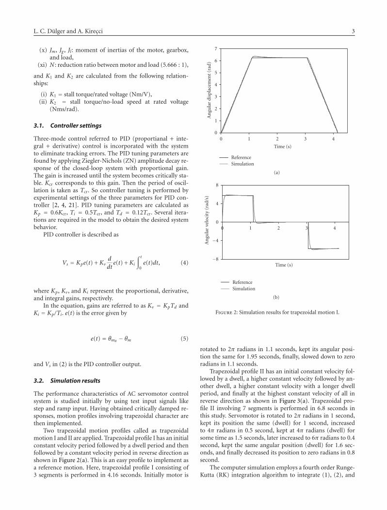
Motion-control program menu allows us to perform trape-zoidal move, also to stop an existing move. A trapezoidal mo-tion is performed by editing the axis number, destination po-sition, maximum velocity, acceleration, and starting velocityas required. When the command is executed, the motion pa-rameters are being sent, and the motion is performed. Theprogram has an ability to record and observe the motor mo-tion graphically. While collecting the data, the total time in-terval in axis position data is to be selected in seconds. Thetime interval between data points to be captured is then se-lected in milliseconds. Here it is taken as 8 milliseconds, andthe PID controller is designed to give zero steady-state errorfor a step input when there is no load.
L. C. Dulger and A. Kirecci 5
5014013012011011
Samples
−1000
2000
5000
8000
Cou
nts
ReferenceExperimental
Figure 4: Experimental results for trapezoidal motion I.
7516014513011511
Samples
−1000
4000
9000
14000
19000
24000
Cou
nts
ReferenceExperimental
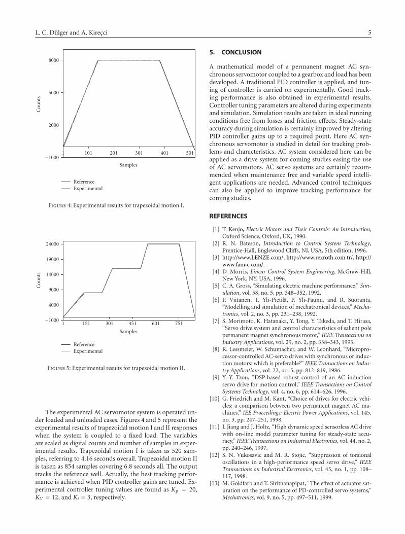
Figure 5: Experimental results for trapezoidal motion II.
The experimental AC servomotor system is operated un-der loaded and unloaded cases. Figures 4 and 5 represent theexperimental results of trapezoidal motion I and II responseswhen the system is coupled to a fixed load. The variablesare scaled as digital counts and number of samples in exper-imental results. Trapezoidal motion I is taken as 520 sam-ples, referring to 4.16 seconds overall. Trapezoidal motion IIis taken as 854 samples covering 6.8 seconds all. The outputtracks the reference well. Actually, the best tracking perfor-mance is achieved when PID controller gains are tuned. Ex-perimental controller tuning values are found as Kp = 20,KV = 12, and Ki = 3, respectively.
5. CONCLUSION
A mathematical model of a permanent magnet AC syn-chronous servomotor coupled to a gearbox and load has beendeveloped. A traditional PID controller is applied, and tun-ing of controller is carried on experimentally. Good track-ing performance is also obtained in experimental results.Controller tuning parameters are altered during experimentsand simulation. Simulation results are taken in ideal runningconditions free from losses and friction effects. Steady-stateaccuracy during simulation is certainly improved by alteringPID controller gains up to a required point. Here AC syn-chronous servomotor is studied in detail for tracking prob-lems and characteristics. AC system considered here can beapplied as a drive system for coming studies easing the useof AC servomotors. AC servo systems are certainly recom-mended when maintenance free and variable speed intelli-gent applications are needed. Advanced control techniquescan also be applied to improve tracking performance forcoming studies.
REFERENCES
[1] T. Kenjo, Electric Motors and Their Controls: An Introduction,Oxford Science, Oxford, UK, 1990.
[2] R. N. Bateson, Introduction to Control System Technology,Prentice-Hall, Englewood Cliffs, NJ, USA, 5th edition, 1996.
[4] D. Morris, Linear Control System Engineering, McGraw-Hill,New York, NY, USA, 1996.
[5] C. A. Gross, “Simulating electric machine performance,” Sim-ulation, vol. 58, no. 5, pp. 348–352, 1992.
[6] P. Viitanen, T. Yli-Pietila, P. Yli-Paunu, and R. Suoranta,“Modelling and simulation of mechatronical devices,” Mecha-tronics, vol. 2, no. 3, pp. 231–238, 1992.
[7] S. Morimoto, K. Hatanaka, Y. Tong, Y. Takeda, and T. Hirasa,“Servo drive system and control characteristics of salient polepermanent magnet synchronous motor,” IEEE Transactions onIndustry Applications, vol. 29, no. 2, pp. 338–343, 1993.
[8] R. Lessmeier, W. Schumacher, and W. Leonhard, “Micropro-cessor-controlled AC-servo drives with synchronous or induc-tion motors: which is preferable?” IEEE Transactions on Indus-try Applications, vol. 22, no. 5, pp. 812–819, 1986.
[9] Y.-Y. Tzou, “DSP-based robust control of an AC inductionservo drive for motion control,” IEEE Transactions on ControlSystems Technology, vol. 4, no. 6, pp. 614–626, 1996.
[10] G. Friedrich and M. Kant, “Choice of drives for electric vehi-cles: a comparison between two permanent magnet AC ma-chines,” IEE Proceedings: Electric Power Applications, vol. 145,no. 3, pp. 247–251, 1998.
[11] J. Jiang and J. Holtz, “High dynamic speed sensorless AC drivewith on-line model parameter tuning for steady-state accu-racy,” IEEE Transactions on Industrial Electronics, vol. 44, no. 2,pp. 240–246, 1997.
[12] S. N. Vukosavic and M. R. Stojic, “Suppression of torsionaloscillations in a high-performance speed servo drive,” IEEETransactions on Industrial Electronics, vol. 45, no. 1, pp. 108–117, 1998.
[13] M. Goldfarb and T. Sirithanapipat, “The effect of actuator sat-uration on the performance of PD-controlled servo systems,”Mechatronics, vol. 9, no. 5, pp. 497–511, 1999.
[14] K. K. Safak and O. S. Turkay, “Experimental identification ofuniversal motor dynamics using neural networks,” Mechatron-ics, vol. 10, no. 8, pp. 881–896, 2000.
[15] G. Guerrero-Ramırez and Yu. Tang, “Motion control of rigidrobots driven by current-fed induction motors,” Mechatronics,vol. 11, no. 1, pp. 13–25, 2001.
[16] G.-J. Wang, C.-T. Fong, and K. J. Chang, “Neural-network-based self-tuning PI controller for precise motion control ofPMAC motors,” IEEE Transactions on Industrial Electronics,vol. 48, no. 2, pp. 408–415, 2001.
[17] Advanced Motion Control Chipset Developer’s Kit Man-ual,Version 2.0.
[18] LENZE, Global Drive-9300 Servo Position Controller Cata-logue.
[19] P. C. Krause and O. Wasynczuk, Electromechanical Motion De-vices, McGraw-Hill, New York, NY, USA, 1989.
[20] C.-M. Ong, Dynamic Simulation of Electric Machinery: UsingMATLAB/SIMULINK, Prentice-Hall, Upper Saddle River, NJ,USA, 1998.
[21] P. Cominos and N. Munro, “PID controllers: recent tuningmethods and design to specification,” IEE Proceedings: ControlTheory and Applications, vol. 149, no. 1, pp. 46–53, 2002.
AUTHOR CONTACT INFORMATION
L. Canan Dulger: Department of Mechanical Engineering,Faculty of Engineering, Gaziantep University, 27310 Gaziantep,Turkey; [email protected]
Ali Kirecci: Department of Mechanical Engineering, Faculty ofEngineering, Gaziantep University, 27310 Gaziantep, Turkey;[email protected]