This study examines the feasibility of a motion and haptic integrated system for the
purpose of controlling a humanoid robotic arm. An Oculus rift head-mounted display was
integrated into the system to determine if there was an observable difference between third-
person and first-person perspective control. We examine different methods of robotic control in
humanoid robots and the precedence of head-mounted displays and motion control in current
literature, as well as look at vibration as a form of haptic feedback to relay the limitations of the
robot. An experiment was completed with the prototype system in which 30 participants were
able to complete the given gross and fine motor testing tasks without fail. A learning period was
observed when comparing completion times of the first task attempted to subsequent tasks. The
majority of participants found the method of control to be intuitive, the inclusion of first-person
perspective to be beneficial, and the vibration feedback to be either inconsequential or confusing
rather than helpful.
ii
Acknowledgements
I would like to thank my research supervisor Anthony Whitehead for providing me this
opportunity among many others, as well as for his experienced direction without which this
would not have been possible. I would also like to thank Dennis Arsenault for helping to create
the framework for this research and for his friendship and guidance. I also thank my family for
supporting me through the years. Finally I thank my wife Jennifer Perry for giving me the
inspiration and motivation to become the person I want to be.
iii
Table of Contents
Abstract ........................................................................................................................................... i Acknowledgements ....................................................................................................................... ii Table of Contents ......................................................................................................................... iii List of Figures ............................................................................................................................... vi List of Tables ............................................................................................................................... vii 1 Chapter: Introduction .......................................................................................................... 1
1.1 Problem statement ........................................................................................................... 1
Table 2: Mean Task Completion Times Based On User Experience ........................................... 41
Table 3: Individual Variable Comparison between Experienced and Non-Experienced Users ... 41
Table 4: Mean Task Completion Times Based On Dominant Hand ............................................ 42
Table 5: Individual Variable Comparison between Left and Right-handed Users ....................... 43
Table 6: Perspective Comparison of Individual Task Completion Times .................................... 45
Table 7: Vibration Comparison of Individual Task Completion Times ....................................... 46
Table 8: Perspective Comparison without Task Learning ............................................................ 49
Table 9: Vibration Comparison without Task Learning ............................................................... 50
1
1 Chapter: Introduction This dissertation outlines a project that involved building a life-size 3D-printed humanoid
robot, through which a user could interact via motion control sensors and virtual reality
technology.
1.1 Problem statement Can a device be created for robotic telepresence with current motion capture technology
that can be intuitive enough for an untrained person to use it effectively without a
learning period?
As communication technologies have become more sophisticated we have begun to see
an emergence of telepresence applications that allow for realistic human interaction without
physical interaction through programs such as skype, facetime or snapchat. As robotic
technologies also become more sophisticated, robotic telepresence has begun to take a more
important position, as it bridges the physical gap of telepresence and allows the user to interact
with the world instead of being a passive observer.
Intuitive robotic control through telepresence also allows for many new and important
applications that may not even be possible through normal human physical interaction. A robot
can be used for assistive purposes, allowing a disabled person the ability to perform difficult
tasks. Robots also have the potential to be stronger and use sensors not available to humans,
providing controllers with superhuman abilities they could not normally possess.
In order to facilitate the ease of use of this emerging technology, it is important to
understand the best practices for maximum usability, one of the most important being system
intuitiveness. This experiment was created with the intention of adding to the current knowledge
base on usability of telepresence robotics.
2
1.2 Hypotheses The following hypotheses were used in the design of the experiment:
1. First-person control will be preferred over third-person control when performing tasks
that require fine motor control, due to the perspective matching what the participant is
familiar with. This preference will be shown by shorter task completion times when
participants are using the Oculus Rift headset for the fine motor task versus the same task
from a third-person perspective.
2. Haptic feedback in the form of vibration will be more effective at relaying the robotic
range-of-motion limits to the user when it is a binary boundary as opposed to a vibration
that slowly increases in intensity as it approaches that boundary. This will be empirically
shown by shorter task completion times when users are subjected to Vibration A as
opposed to Vibration B.
1.3 Contribution This study offers the following contributions to current literature on motion control of humanoid
robotics:
Although there is precedent in the literature for motion-controlled telepresence robots,
this study demonstrates a system that is relatively inexpensive for control as well as an
equivalent 3D-printed robotic build, suggesting a system for maximal accessibility.
The prototype control system describes an inertial control system that uses natural human
motion as intuitive control, as rated by the majority of participants (83%). No failures were
recorded on given tasks and no prior training was given.
By using inertial sensors, we describe a scalable design that could be extended to include
other body joints or adapted to include more robotic movements.
We suggest a system that does not adapt recorded human movement to fit robotic
restraints but instead influences human movement to constrain itself to the limitations of the
robotic avatar. This allows more direct control of robotic parts without diminishing the
intuitiveness of human movement while also providing a more instinctive reaction from the
3
robot. This is also suggested as a possible solution to the problem of latency in human-robotic
movement matching.
Our system also suggests that more research needs to be conducted to determine if a
perspective difference has a significant impact on robotic control tasks.
The study describes the importance of usable feedback in relating the robotic limitations
to the human controller, furthers the understanding of this feedback, and suggests possible areas
for future research into feedback for telepresence robot control.
Finally, the research clearly defines the existence of a learning effect even though natural
motion is used as the form of control. This learning effect is analysed in respect to the
intuitiveness of the system as well as the effect on the hypotheses and results.
1.4 Thesis Overview The thesis begins with an outline of the contributions of this experiment. We then
perform a survey of current motion capture technology and its relevance to robotic telepresence,
which helped form the hypotheses of this research, in Chapter 2: Background. A possible gap in
the research literature is identified and is also used in the experiment formation. The current
literature on telepresence motion control and perspective is used as a basis for this experiment.
The constructed device is then described in detail in the subsequent Section 3.1: Device.
This includes the aforementioned humanoid robot, the motion control system, the haptic
feedback jacket and the virtual reality headset used for perspective difference control. The
possible limitations of the prototype device are also discussed in detail.
Section 3.2: Experiment outlines the experiment that was completed with the prototype
device. This experiment involved a sample of 30 participants that used human motion to control
the humanoid robot in a series of tasks with two separate degrees of motor control, two separate
haptic feedback styles, and two separate perspective views. The participants completed a task
for each possible state of these variables. The following Chapter 4: Results describes the results
of this experiment, offers a statistical analysis and discusses the self-reported results of
participants on the post-study questionnaire.
4
Finally, in Chapter 5: Conclusions and following Section 5.2: Discussion we discuss the
outcome of the experiment in regards to our originally proposed hypotheses, reconvene on the
viability of the prototype post-study, and describe possible future areas of research with respect
to the limitations of this study.
5
2 Chapter: Background
This chapter outlines current methods of motion control for human motion capture,
including the advantages and disadvantages of common methods. This will then be given
context in current research into motion control of robotics. We will then describe an observed
gap in human-robotic interaction research regarding different perspective views for robotic
control in the context of telepresence robotics and virtual presence.
Three of the most common types of human motion tracking are optical marker-based
systems, optical depth camera systems, and inertial measurement unit (IMU) systems. These are
presented and compared in Sections 2.1 to 2.3. Robot control is covered in Section 2.2, where
we also discuss telepresence control using these systems. Perspective in robotics is then
discussed in Section 2.5, followed by a review of the current state of wearable computing in
Section 2.7.
2.1 Marker-Based Motion Capture Systems The traditional form of motion capture involves a sterile room of infrared cameras that
surround a capture space (as in the Vicon system)[9]. The subject must wear reflective markers
specifically designed for camera capture. The advantage of marker capture systems are in a
much greater capture accuracy, generally found to be less than a millimeter [10][52][53]. This is
therefore very useful for accurate capture of slight motions.
Capture accuracy, however, can be affected by a number of environmental factors. These
include: marker size / distance [11][12], number of cameras / positioning [11][12][13],
environmental lighting [12], and occlusion as a result of body positioning or environmental
effects [13]. Marker size can affect how easily the camera system can detect the position of the
marker, and a system with more cameras can more easily detect markers due to the increased
capture area and angles of detection. Occlusion refers to the accidental covering of markers
through body positioning, leading the markers to be obscured from the point of view of the
capture cameras.
6
The relative high cost of these systems make them unreasonable for general use.
Moreover, the space requirements make such capture systems only usable in one preconfigured
environment [14] (see Figure 1: Camera Motion Capture System Environment). As a
general input device, the calibration requirements and the mere fact that they must be used in
very controlled environments makes such systems unsuitable for many applications, especially
robot control in unconstrained environments, which this thesis addresses.
Figure 1: Camera Motion Capture System Environment
2.2 Depth Cameras Depth camera tracking is becoming more popular due to inexpensive entertainment
devices such as Microsoft’s Kinect [30][54], which is composed of an infrared emitter, depth
camera and an RGB camera, as well as a development kit that allows for skeletal joint tracking
and facial recognition. The Kinect system senses depth by emitting an infrared light pattern into
the environment and creating a depth map of these dots using the infrared camera [31] (see
7
Figure 2: Kinect Infrared Capture). For skeletal tracking, the Kinect uses a large library of
depth-sensor training data to differentiate separate human body parts, and then estimates the
locations of skeletal joints on the current image from the point cloud data that the depth sensor
generates. This library is included with the Kinect sensor, making skeletal tracking very
accessible.
Figure 2: Kinect Infrared Capture
Depth camera tracking like the Kinect also suffers the same occlusion disadvantage as
marker capture systems although usually to a much greater degree as a result of a smaller range
of capture corresponding to a smaller number of cameras. As well, depth cameras that use an
infrared pattern projection system are only useful in an indoor environment.
8
2.3 Inertial Measurement Units (IMUs) Inertial measurement sensor motion capture requires the direct application of a series of
fused sensors (including accelerometers, gyroscopes and magnetometers) to the body. This type
of sensor network has been shown to be useful in entertainment and exercise motion-capture
applications, both for its relative low-cost and encouragement of active play [17][18][19].
The main advantage of wearable IMU sensors is the ability to track motion in any
environment thus increasing the number of useful applications [14] as well as avoiding the issues
of occlusion that are common in optical systems. A wireless IMU system allows for captures in
a natural setting for situations that would be difficult to capture traditionally (such as skiing [14]
or skydiving), as well as the convenience of motion capture not being tethered to a single
location.
2.3.1 The Accuracy Myth There is a perceived inaccuracy of IMU systems when compared to traditional optical
motion capture systems due to the suggested high rate of sensor rotation error during dynamic
movement [4][5]. This is especially amplified when compared to optical tracking systems, like
the Vicon camera system, which boasts sub-millimeter accuracy [2] in their marketing efforts.
However, a recent study by Godwin et al. [2] observed modern IMU error rates and found a
rotational error of less than a degree when the sensor is motionless, and less than four degrees
during constant motion, and found similar error rates when compared to the optical Vicon system
in an ideal environment. Studies have also determined that calibration routines can be used with
IMU sensors to further reduce tracking error by matching sensor coordinate systems to an
external system [2][3]. One such study that provides the sensor framework for this experiment
observed a significant reduction in sensor drift errors when calibration was applied [1] without
the use of magnetometer anchoring. Magnetometer anchoring would further improve the
accuracy of such a system. This suggests that modern IMU sensors are suitable for most
applications that traditional optical motion tracking is currently used for when employing custom
fusion algorithms [4]. Moreover, the broader range of use in different situations (i.e. outdoors)
makes them particularly attractive for motion capture applications in unconstrained
environments.
9
2.4 Robotic control A noted problem in robotic control using natural human movement is the ability of the
robot to effectively mimic swift and complex human motion. A study by Pollard et al. [6]
suggested an algorithmic solution in which motion data including joint velocity and angles could
be scaled to constrain the human motion to a humanoid robot’s range of motion. This technique
has its drawbacks, as subtle human movements are lost. This technique is also only effective
with pre-recorded motion because of the previously mentioned difficulty of matching robot
speed and precision to human motions as well as the time complexity needed to scale the
movements.
A possible direction of research could come from studies applying real-time human
motion to animated characters. Shin et al. [7] suggested an importance-based real-time kinematic
interpretation algorithm that would decide the importance of joint angles and end effector
locations based on situation. Instead of just using the desired end position of limbs like hand
position for a grasping task, this approach takes into account joint angles and gives them an
importance level to preserve using a series of algorithms. This approach still retains the problem
of discrete aspects of the human motion not being retained on a 1-to-1 scale.
Another possible direction is gesture recognition [24], which has the advantage of being
able to detect specific motions in real-time, and map them to repeatable and predictable robot
movement. This, however, is not useful for tasks that require unique motions not found in the
gesture library, or for tasks that require fine motor control precision as critical for success.
We next examine research in robotic telepresence control for both optical and IMU based
systems.
2.4.1 Telepresence Control Using Optical Systems Due to the relatively low barrier-of-entry, the majority of studies using optical-based real-
time motion capture for robotic control have used depth cameras similar to Microsoft’s Kinect
sensor, whose development kit provides skeletal tracking algorithms with the camera at a low
cost. A multitude of studies have provided different proof-of-concept control schemes using the
Kinect as the main control input [48][49][50][51].
10
Many studies have used the Kinect’s built-in tracking system as the basis of gesture
recognition for robotic teleoperation with some degree of success [35][36], allowing the user to
relate natural motions to robotic actions, although not on a 1-to-1 scale.
The Kinect sensor is also capable of using its skeletal tracking software to transmit joint
angles to a robotic counterpart in real-time [33][34][37]. However, given the small capture space
and single-camera fidelity of the capture, the accuracy is limited, as are the practical
applications.
2.4.2 Telepresence Control Using IMU systems There is some precedence of using IMU sensor systems for robotic motion control. One
such study by Miller et. al. [15] developed an IMU system for controlling NASA’s Robonaut
[20], a humanoid telepresence robot designed for use on the international space station. They
concluded that such a system could reliably control the Robonaut through telepresence
movement while retaining the advantages of IMU systems. The problem of human-robot motion
matching was again indicated, wherein the human either moves too fast for the robot servos to
match or tries motion to compensate for the latency of the robot, suggesting that haptic feedback
could alleviate the issue.
Another similar robotic build is the Telebot prototype [16], which includes IMU motion
control and a head-mounted display, although no publications have been released aside from the
initial design of the prototype.
IMU systems can also be useful in assistive robotics, tracking user movement and
providing situational support [27].
As modern IMU sensors become more accurate, it seems like an obvious choice for real-
time telepresence avatar applications due to the low cost of the sensors, the ease-of-setup, the
avoidance of environmental problems like occlusion, and the option for use in unconstrained
environments.
11
2.4.3 Haptic Feedback in Robotic Control There is some precedence of using haptic feedback in robotic control. This is usually used
as a form of sensory feedback to give the user a sense of presence by virtually simulating touching
an object, as well as to allow for more accurate control by providing more information about the
robot’s environment, as used in [70][71]. This is especially useful in robotic-assisted surgery
systems, in operations that normally are more accurate with a sense of touch (like being able to
feel the flesh when suturing) [69].
In this study, we do not use haptic feedback in the traditional form of creating a virtual
object, but instead use it to create a tangible virtual boundary to allow the user to “feel” the limits
of the robot.
2.5 Perspective Robotics and Virtual Reality The release of the Oculus Rift [8] in 2012 provided the first easily-attainable head
tracking and virtual reality head-mounted display (HMD). This also allowed for more feasible
research into the domain of virtual reality, the implications of which in turn have driven more
research into motion control to allow for a more immersive virtual experience in terms of
presence.
With the onset of this increased availability of these virtual reality systems, many
telepresence robotics systems have integrated some form HMD to provide the perspective of the
robot to the user, as in [15][16]. However, a possible limitation of HMD technology is the onset
of “cybersickness” that has been reported when using virtual reality and includes symptoms of
nausea, discomfort and disorientation [40][46]. It is possible that individual differences may
leave some users more susceptible to cybersickness than others [41]. The underlying cause of
this sickness is not yet completely known and is still a prominent topic in research as virtual
reality headsets become more mainstream since this side effect may slow adoption of the
technology.
12
2.5.1 Perspective in Robotic Control A discernable gap in the research literature is evident when it comes to the most efficient
perspective for telepresence or avatar robotic control, with the majority of studies not addressing
the possibility of perspective differences at all. We have seen from virtual reality studies that
there is some debate on the use of different perspective modes. The majority of studies done
with motion control of a robotic avatar either utilize a third person perspective in the same room
as the controller (as in [24][33][34][37]), or a first person perspective for use with telepresence
robotics without questioning the effect different perspectives could have on the operation (as in
[15],[16],[32]). Some studies provide the assumption that a first-person perspective will provide
a feeling of virtual presence to the user due to an egocentric perspective or a more natural control
[32], but this assumption has not been adequately explored or compared. Formal comparisons of
perspective differences do not exist in these studies.
An experiment on robotic teleoperation by Jun [38] suggested that more research into
perspective differences is required, when it was found that a group with a first-person
perspective performed with 25% more elapsed time than a group that was allowed both third and
first person perspectives. A study by Okura et al. [39] also confirmed that the addition of
another viewpoint allowed for more accurate teleoperation.
The question of presence correlation to viewpoint has been studied in the field of virtual
reality by Rybarczyk et al. [42], which found that a third person view allowed for more precise
learned control of the avatar’s limbs, although the self-reported feeling of presence was higher in
a first-person perspective. The question of whether a perspective difference is beneficial in
controlling telepresence robotic avatars becomes the basis of our first hypothesis.
2.6 Human-Robot Interaction Human-Robot Interaction (HRI) has many interesting aspects that could lead to important
research questions, however for the purposes of this study we focus mainly on control
interactions as opposed to autonomous robotic interactions with humans. Although this study
focuses on robot telepresence control, it is still important to also take into consideration the
perceived interaction with the avatar.
13
Tsui et al. [25] performed a survey of minimal non-manipulative telepresence robots and
found that human poses lead to more perceived positive interactions with coworkers (i.e. eye
contact, facing coworkers, and adaptive vocalization). It was also found that a control scheme
that can reduce the cognitive load of the user would lead to more positive interactions, so an
intuitive system is ideal.
Kristofferson et al. [28] found a correlation between robot formation (i.e. spatial position
and rotation) with the human subject and perceived quality of interaction as well as feeling of
presence for the controller. It was hypothesized that if the telepresence avatar moved into a
similar formation as a human would when interacting (such as following, face-to-face or side-by-
side) there would be a much higher perception of co-presence.
It was also found that unconscious behaviours such as breathing or blinking help to
improve the quality of interaction by Sakamoto et al. [29], who built a realistic android for
robotic telepresence. With this addition the human participants felt more of a presence
interacting with the android than with the same controller through a video monitor.
If the consensus is supported that robotic interactions are more pleasant for the human
when having human-like interactions, then it stands to reason that human-like motion would also
be a preferred method of interaction, as well as being an intuitive method of control.
2.6.1 Assistive Robotics In recent years, robots have been emerging as assistive devices for certain at-risk
populations such as seniors or the disabled. Some of these devices are designed with physical
disability in mind, such as addressing mobility [73] or physical rehabilitation [74]. Some have
also been designed as companion robots, and have been shown to be just as effective with
seniors as real pets in reducing stress, like Paro the robotic seal [75].
Robots have also begun to be used to assist those with social disabilities [76], such as the
Keepon robot [72], which was designed to help children on the autism spectrum interact and
understand non-verbal expression and emotion.
14
Usually, these studies focus on only one side, being either physically assistive or socially
assistive, with few studies examining a system that provides both.
2.7 Wearable Computing and Motion Control Optical motion tracking requires a lab environment, which increases costs and limits the
situational context of capture, and depth cameras like the Kinect have a very limited frame of
capture. In recent years, wearable computers have seen a successful emergence in the
commercial market. Devices range from simple Bluetooth and cell-phone sensors to the recent
augmented reality devices, such as the Google Glass [23] head-mounted display which uses a
sensor similar to the inertial sensors used in this study. The Fitbit [21] pedometer is another
example of a commercially successful wearable that utilizes an accelerometer for relatively basic
motion tracking. The Fitbit reported a $745 million dollar net revenue in 2014 up from $271
million in 2013 [22], clearly demonstrating a public demand for new and useful wearable
devices.
As the demand for wearable computing increases, it stands to reason that the population
of users will be more accepting of wearable sensors as a method of control for many
applications. Many sensors used in motion capture, such as accelerometers and gyroscopes,
already exist in modern user’s smartphone devices. Studies have been completed to examine the
viability of using just the sensors in these devices for motion capture and human motion
recognition [58][59], such as examining algorithms for accurate capture from a loosely attached
device [56], or using the smartphone data to determine if a user has fallen and in peril
[57][60][61]. This type of motion monitoring may become preferred by the general user, as it
does not require the application of additional sensors or markers, and only requires a device
which is already being carried on his or her person. However, due to the complexity of motion
that is needed, this type of motion capture is not advanced enough to be used for our robotic
teleoperation purposes.
15
3 Chapter: Method
3.1 Device
3.1.1 Overview The prototype device consists of four main parts: the humanoid robot, the motion control
sensors, the haptic jacket and the Oculus Rift head-mounted display, as shown in Figure 3: Full
Device Overview. The user wears the haptic jacket to which the motion sensors as well as the
vibration motors are attached in order to control the humanoid robot using normal body motion.
All four are connected to the main experiment terminal, which is responsible for control of all of
the components.
Figure 3: Full Device Overview
16
3.1.2 Humanoid Robot
3.1.2.1 Overview
An entire human-sized upper torso was 3D-printed and is functional including arm, hand,
head and jaw motion. However, for the purposes of this experiment only the left arm was utilized
with three points of rotation. Servo motors control the motion of the 3D-printed parts, which are
in turn controlled by an Arduino microcontroller directly connected to the experiment terminal
(see Figure 4: Robotic Wiring Overview).
Figure 4: Robotic Wiring Overview
17
3.1.2.2 Open-Source Framework
The 3D-printed shell of the robot is based upon a series of open-source 3D model
blueprints which the creators have dubbed InMoov [43]. The project’s creators set out to
construct a repository of files that could be readily available for anyone to use to build their own
humanoid robot at a reduced cost when compared to traditional research robotics of similar
design, due to the relative lower cost of 3D-printing custom prototypes as well as the benefit of
easy CAD software integration [65]. These designs were used in the prototype to reduce costs as
well as examine the viability of a personal 3D-printed robot, which led to some limitations of the
prototype as well.
The robot parts were printed in ABS plastic using a print bed with a maximum part size
of 123 centimeters.
3.1.2.3 Servo Motion
Two types of servo motors were used to allow locomotion: the Hitec 645MG servo and
the Hitec 805BB servo, the latter being a larger servo capable of more torque [66][67]. The
larger servos were used in places of the arm design that required higher torque for operation,
namely the shoulder and bicep rotation. Gearboxes were also put in place at these locations to
maximize operation power. The smaller servos were used to rotate the wrist and to pull the
ligaments connected to the finger joints. The placement is outlined in Figure 5: Servo
Locations/Rotation.
18
Figure 5: Servo Locations/Rotation
The servo motors used in this prototype rotate around one plane with a maximum rotation
angle of 180 degrees. To allow for greater rotation of the servos so that the gearboxes
themselves could rotate the robotic parts 180 degrees, the servos were modified by extracting the
servo potentiometer and removing the rotation lock (see Figure 6: Potentiometer Extraction).
The potentiometer is the component of the servo that keeps track of the servo angle. The
potentiometer of the servo was then installed directly onto the point of rotation that it controlled
so that the software could directly regulate the angle of the arm joints as opposed to the servo
angle.
19
Figure 6: Potentiometer Extraction
The benefit of this technique can most easily be seen when observing the gearbox used
for shoulder and bicep rotation, as displayed in Figure 7: Gearbox Internal Diagram. The
gearbox is necessary on the planes of rotation with more weight to create a usable amount of
torque, and thus to enable a full 180 degree rotation the extraction and reapplication of the servo
potentiometer was also necessary.
20
Figure 7: Gearbox Internal Diagram
3.1.2.4 Arduino Microcontroller
Arduino is an open-source hardware microcontroller and software IDE combination [46]
that allowed the robot servos to be easily controlled by the main program through a serial
connection. The Arduino board is especially useful for prototyping as its functions can quickly
be changed by uploading new code to the flash memory. The Arduino IDE also contains built in
C++ libraries for servo functions, flex sensor functions and analog sensor functions used in this
prototype.
The digital servos are controlled through the Arduino pins, and are kept in constant
power to avoid vibrations and inaccuracies. The Arduino is sent updated servo positions every
program cycle from the main program, and constantly updates the servo position. The servo
position will only be updated should a difference of more than half a degree of rotation be
detected from the IMU sensors.
21
3.1.3 Motion Controllers
3.1.3.1 Overview
This study utilized inertial measurement units (IMUs) to track the motion of the
participant at three locations on their left arm. The IMU sensor used was Microchip’s now-
unsupported Motion Sensing Demo Board, which is composed of an accelerometer and a
gyroscope chipset [68]. The device also required a wireless radio receiver connected via USB to
the main experiment terminal to receive data from the IMU sensor (as seen in Figure 8: IMU
Chipset and Receiver). These specific sensors were used because the framework of this
experiment builds upon a previous experiment from the same lab by Dennis Arsenault [1].
Figure 8: IMU Chipset and Receiver
3.1.3.2 Quaternion Output
Each IMU sensor provides a rotational value as output in the form of a quaternion. Upon
start-up, the sensor creates its own reference frame by detecting gravity and mapping this as its
z-axis (or up/down axis) [1][68]. This data is then matched to the coordinate system of the main
Unity program. For more information on matching the reference frames and quaternion
transformation, view the previous study [1].
Before each task of the program begins, the user must be sitting facing forward, with the
elbow of their left arm bent at as close to a 90 degree angle as possible, as outlined in Figure 9:
User Starting Position. This ensures that the coordinate system of the sensors can match the
22
forward-facing axis of the main Unity program co-ordinate system (and in effect the robotic arm
position) by applying an initial offset on start-up. The offset is created by averaging a range of
quaternion readings on program start-up, and applying that difference to readings taken over the
course of the task. This offset is created and applied at the beginning of every task to reduce
sensor error, and thus the user must assume the starting position before each task begins. This
also ensures that every participant begins each task of the experiment from the same position.
Figure 9: User Starting Position
Gimbal lock, a common concern in engineering that involves multi-axis rotations such as
with robotic arm motion, is not a problem in our prototype. Our arm prototype has three points
of rotation mapped to the data from the IMUs. Each rotation in the robotic arm utilizes one
servo and thus each point only rotates on a single plane that is limited to less than 180 degrees of
rotation and does not overlap any other rotation plane (see Figure 10: Robotic Planes of
Rotation). These rotations were limited to prevent prototype breakage. Therefore, although we
do use quaternion data from the IMU sensors, it can be safely converted to Euler rotation angles
as we are only interested in one plane of rotation for each sensor for the purposes of this
experiment.
23
Figure 10: Robotic Planes of Rotation
A previous experiment using the same sensors employed in this study determined that in
order to minimize unwanted noise and sensor drift, the sensors would need to remain motionless
for a minimum of 13 seconds upon start-up [1]. It was estimated that with this particular IMU
the 13 second wait time was the minimum amount of time needed for the sensor fusion algorithm
to engage properly. It is unknown whether this issue was resolved as this specific sensor is no
longer supported by the manufacturer.
3.1.4 Haptic Jacket
3.1.4.1 Overview
The haptic jacket, aside from being a convenient way to attach and immobilize the IMU
sensors on the participant, also housed the wiring and vibration motors needed to provide haptic
24
feedback. This feedback differs from other types of haptic feedback in robotics, in that it is used
specifically as a signal to notify the participant when they were near or outside of the robot’s
range of motion, as opposed to attempting to recreate a feeling of holding or touching an object
through force feedback
Using vibration motors as output, two styles of vibration feedback were designed.
Vibration A style indicates a simple binary style, where the vibration is either at a constant, full
strength or non-existent. Vibration B style indicates a vibration style where both the strength
and frequency of the vibration is variable depending on user input.
Like the robot servo control, the vibration motors in the haptic jacket were also driven by
an Arduino microcontroller sewn into the back of the jacket. The jacket then was directly
connected to the experiment computer terminal via USB cable, which allowed for quick transfer
of signals and data, as well as USB power. A wireless setup would be ideal for applications that
involve more movement, but for the purposes of this experiment the participants were seated and
thus a direct connection was preferred. This setup can be seen in Figure 11: Haptic Jacket
Wiring.
25
Figure 11: Haptic Jacket Wiring
3.1.4.2 IMU housing
In order to prevent shifting of the motion sensors on the body, plastic housings were 3D
printed and attached securely to the jacket (see Figure 12: IMU Housing on Jacket). To
prevent any further shifting, Velcro straps were also employed at the site of the 3D printed
housings, and tightened while the participant was wearing the jacket. This ensured that the
sensors would be able to read body movements as accurately as possible by preventing unwanted
noise caused by the sensor moving over time.
26
Figure 12: IMU Housing on Jacket
3.1.4.3 Vibration Motors and Pulse Width Modulation
The vibration motors were sewn into the haptic jacket at locations beside each sensor that
they were meant to indicate. The motors were positioned at a suitable distance as to not interfere
with the IMUs or cause any unwanted noise, while still being close enough to each sensor that it
would be clear where the indication was coming from.
The type of motor used was the VPM2 Vibration disk motor, which has a maximum
operating voltage of 3.5V [45]. In order to change the voltage applied to the vibration motor by
the Arduino (which supplies 5V by default), a pulse width modulation signal was used. Pulse
width modulation is a technique where the full high 5V signal is sent in rapid on-off succession
to simulate the desired voltage output over time [44]. The formula for the vibration used can be
seen as:
27
Vavg = Vhigh * F
Where Vavg is the desired voltage output, Vhigh is the voltage provided by the
microcontroller, and F is the frequency of the on/off pulse.
For our purposes, we can calculate the range of frequencies using our desired output voltages for
each motor: the operating range of 2.5-3.5 volts [45].
Vavg = Vhigh * F 3.5 = 5 * F F = 0.7 and
Vavg = Vhigh * F 2.5 = 5* F F = 0.5
Therefore, the range of possible on/off cycles we use in order to simulate our operating
voltages ranges from 50% to 70% of one normal clock cycle. This range now represents the
strength range of each motor that was possible. This allowed the strength of the vibration disk to
be readily controlled by software and different vibration strengths to be varied by situation
depending on the input of the participant.
3.1.4.4 Flex Glove
A glove was also fashioned to the haptic jacket in order to allow finger control. Due to
the lack of robustness of the finger ligament design, the fingers had a simple binary state of open
or closed. The flex glove was a simple work glove outfitted with a flex sensor that detected the
angle of the user’s fingers to detect an open or closed state.
3.1.5 Oculus Rift Headset In order to give a first-person perspective, two high-definition webcams were mounted in
the eye sockets of the robot. The webcam image was then sent to the display of an Oculus Rift
Dev Kit 1 virtual reality headset. While the Oculus has mainly been used for virtual reality
gaming in the past, it was used in this prototype to simulate perspective as if the user had the
28
view of the robot. This design should allow the user to better judge the robot’s components in 3D
space.
3.1.6 Software A Unity program was used as the highest level program running on the experiment
terminal responsible for the direction of all of the components. The outline of the software
hierarchy can be seen in Figure 13: Software Hierarchy. The choice to use Unity [62], an
object-oriented 3D video game engine, was made for a number of reasons. The first reason is
that Unity has 3D matrix mathematic functions built into the scripting language that made
working with quaternion data much simpler than coding those functions by hand. As well, the
previous study by Dennis Arsenault [1] had used the same IMU sensors within the Unity
architecture, and the IMU framework of this study was based upon that previous framework.
Finally, Unity was the easiest way to bring the Oculus headset into the prototype as well as
deliver webcam images to the Oculus display, as Oculus has developed a Unity package for use
with their headset [63], allowing for easy system integration.
29
Figure 13: Software Hierarchy
Arduino microcontrollers directly controlled all of the physical components, namely the
servo motion, vibration feedback and flex sensors. In this prototype they acted as an
intermediary between the physical components and the main Unity program receiving quaternion
data from the IMUs. The main Unity program interpreted the received quaternion data and sent
an appropriate response command to the Arduino controlling the servo motors and the Arduino
controlling the haptic feedback.
30
3.1.7 Device Limitations
3.1.7.1 Overview
The device had some unavoidable limitations, both expected and unexpected. These
limitations became apparent during the build process and during pilot tests, and the design of the
experiment was adjusted to try and minimize these limitations affecting experiment results.
Some limitations were unavoidable due to the small scope of this project, and would be good
topics for future research.
3.1.7.2 Servo Latency
A major problem with the robot design is the difference in possible movement times
between human arm motion and the robotic arm components. As we can see in Figure 14,
which shows the average of ten trials for the robot joints to move 20 degrees in rotation, the
further away from the controlling servo the point of rotation is, the longer it takes to move the
part. In terms of human parts, this means the part corresponding to bicep rotation moves
significantly slower than wrist rotation, which is almost instant. This is most likely due to the
fact that as we move further from the tip of the hand the servo is required to move more weight.
The shoulder servo also tends to move faster when rotating downwards as opposed to upwards
due to the benefit of the force of gravity.
31
Figure 14: Servo Latency Times for 20 Degrees of Rotation
3.1.7.3 Vibration Disconnect
A secondary problem to the lag of robotic arm motion is the vibration not coinciding with
that motion. By design, the vibration feedback is enabled when the user’s arm leaves the
possible range of motion of the robotic arm, which is monitored by the IMU sensors and not the
actual robotic arm locations. The human motion could be completed much quicker than the
robotic motion, and thus vibration feedback could happen while the robotic arm is still in motion
leading to confusion. This also could lead to a mental disconnect between the user’s body
positioning and the robotic body positioning if the user did not use slow enough movements.
3.1.7.4 Fixed Perspective
Another product of the servo latency was the immobilization of the robot head, meaning
the first-person perspective was fixed. The choice to fix the first-person perspective was made
during pilot studies when it was found that robot head motion varied too much from user head
motion due to the speed at which the head can turn, which resulted in self-reported feelings of
motion sickness. It is possible that a fixed first-person perspective was a detriment to the user’s
32
depth perception, but in order to combat this the field of view was made such that the entire
experiment area and robotic arm could be seen at all times. Also, the third person view was
immobilized by having the user sit in one position behind the robot without moving around the
experiment area, for a more fair comparison in perspective.
3.1.7.5 Breakage
A significant problem with the prototype was part breakage. Due to the limit in size that
a part could be 3D printed, the build consisted of many small parts which lead to many break
points. For this reason another method or design in building the robot framework is suggested.
It is possible that a metal frame may have been more stable however the weight of the
arm would have increased significantly and a more powerful servo motor and gearbox system
would need to be designed to allow locomotion. It would also drive up costs, so this option was
not explored.
3.1.7.6 Body Shape Differences
A number of users noted on the post-study questionnaire that a better-fitting jacket would
be beneficial. It is possible that shorter limb length and finger length may have had an effect on
the ease of use of the prototype as only one size of jacket was created, but this was not explored
in any meaningful way.
3.2 Experiment
3.2.1 Overview The study involved one scheduled 60-minute session per participant, including time to fill
out a questionnaire at the end of the session. Testing involved a total of eight tasks to be
completed by the participant with different combinations of variables for each task. The session
can be broken down into two main blocks of tasks, involving completing four tasks with and
without the Oculus Rift (OR) virtual reality headset to obtain the first-person and third-person
33
perspectives of the robot. As well, each task needed to be completed using both of the different
types of haptic feedback. The two tasks that needed to be performed with all combinations of
these variables involved using the motion controllers to objectively move the robot arm with
both a gross motor movement task and a fine motor movement task. The various combinations
are outlined in Table 1: Task Outline.
Vibration A Vibration B
3rd Person View
(without Oculus)
1 Fine motor task and
1 Gross motor task
1 Fine motor task and
1 Gross motor task
1st Person View
(with Oculus)
1 Fine motor task and
1 Gross motor task
1 Fine motor task and
1 Gross motor task
Table 1: Task Outline
Task time completion was used as the main method of measuring usability by comparing
the time it took participants to complete each task under the various testing conditions. By
comparing each participant to themselves, the overall task time is not as important as the
differences between tasks with different variables for each individual participant, and can give us
a clear picture of each variable’s effect on the usability of the system.
When any portion of the robot arm has reached its limit of range, haptic feedback in the
form of vibration was relayed back to the user to signify this limit. This vibration is the same
vibration technology that is found in modern cell phones, and should be familiar to most
participants.
After the 8 motor tasks were complete, the participants were asked to complete a
questionnaire regarding the tasks completed and devices used in the session, as well as provide
their preferences and opinions about the prototype and technology. The goal of the study was to
examine the usability of the motion controllers, to determine if there was a difference in usability
when using the Oculus headset, and to determine if one style of vibration feedback was a more
effective form of vibration for notifying the participant about the range restrictions of the robot.
34
3.2.2 Perspective The main hypothesis of this study was that a first-person perspective would be more
beneficial and intuitive in controlling a telepresence robot using real-world movements for fine
motor tasks than a third-person perspective. In order to examine this hypothesis, a facet of the
experiment needed to show empirical differences between tasks with and without the Oculus Rift
head-mounted display in use, as well as participants’ self-reported preferences. The two
perspectives used can be seen in Figure 15: Perspective Difference.
Figure 15: Perspective Difference
35
3.2.3 Haptic Feedback A secondary facet to the study was to determine if haptic feedback in the form of
vibration would be useful in a prototype such as this in order to notify the participants when they
had reached the limits of the robot. In order to test this hypothesis, each task was completed for
two different vibration styles. Vibration style A was a binary style, in that it was fully on when
the participant went out of range on that particular motion sensor, and completely off when
inside the robot’s range of motion. Vibration style B was a strength style vibration that
corresponded with how close the participant was to the invisible boundary indicating the end of
the robot’s range of motion (meaning it ramped up the strength values of the vibration depending
on the number of degrees away from that boundary).
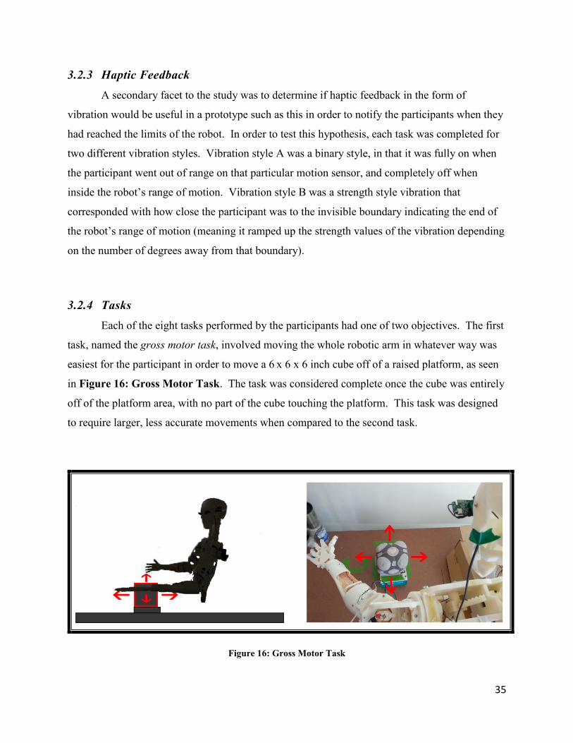
3.2.4 Tasks Each of the eight tasks performed by the participants had one of two objectives. The first
task, named the gross motor task, involved moving the whole robotic arm in whatever way was
easiest for the participant in order to move a 6 x 6 x 6 inch cube off of a raised platform, as seen
in Figure 16: Gross Motor Task. The task was considered complete once the cube was entirely
off of the platform area, with no part of the cube touching the platform. This task was designed
to require larger, less accurate movements when compared to the second task.
Figure 16: Gross Motor Task
36
The second task objective, named the fine motor task, involved grasping a mug by its
handle on a raised platform without knocking the mug off, as seen in Figure 17: Fine Motor
Task. Due to prototype strength limitations, and in order to reduce strain on the prototype, the
participant was not required to lift the mug but instead the task was considered complete if the
participant could position at least one finger around the handle as if they were about to lift the
mug. This task required a finer control of the prototype than the gross motor task in order to
position the robot fingers within the handle.
Figure 17: Fine Motor Task
Both of these tasks were repeated four times in order to test the different variables of
perspective (with or without the head-mounted display) and haptic feedback (different styles of
vibration) as outlined in Table 1: Task Outline. A maximum time of five minutes was allotted
for each task before it would be considered a failure. None of the participants reached the
maximum cut-off time for any task, meaning all participants were able to complete all tasks.
3.2.5 Procedure The specific procedure of the experiment was as follows:
37
1. Participants were asked to read and sign the waiver as per university ethics regulations
(see Appendix A).
2. The researcher then gave an oral background of the project, making sure to cover the
points outlined in the pre-experiment script (see Appendix E). This was to introduce the
experiment and all of its elements as well as all of the components of the device, and
allow the participant to voice any questions or concerns prior to the commencement of
the experiment. This was also to ensure that the participant understood the written waiver
and to reiterate the key points of the waiver regarding privacy and the option to terminate
the experiment at any time if they were uncomfortable for any reason. None of the
participants reported any discomfort or declined participation once the study began.
3. The researcher then used a random number generator to determine the order of the tasks.
This was to mitigate any learning effect that might interfere with final results. The order
of tasks was then noted in the log file so that it could be later referenced.
4. The participant then sat in a chair directly behind the robot at a distance of four feet. The
researcher aided the participant in putting on the haptic jacket and flex glove, if needed.
5. The researcher inserted the batteries into the IMUs, and after waiting the appropriate
amount of time to prevent sensor drift (see Section 3.1.3.2), attached the sensors to the
participant. It is important to complete this step as close to actual testing as possible in
order to prevent unwanted sensor drift.
6. The video recorder was enabled at this time.
7. Following the task order determined earlier, the researcher then reiterated the objective of
the current task as well as the type of vibration the participant should expect.
8. The participant was instructed to move to the starting position and the program was
started. The participant then completed the laid out task without further instruction from
the researcher.
9. After task completion, the IMUs were reset, again to counteract sensor drift. During this
time the researcher asked the participant if they felt any discomfort, and ensured they
were willing to continue. This is especially important after tasks involving the Oculus
HMD, due to the potential for VR Sickness (as discussed in Section 2.5).
10. Steps 7 and 8 were repeated until all tasks were completed by the participant.
38
11. Following the final task, the researcher helped the participant remove the testing
equipment, and directed them to complete the post-study questionnaire (see Appendix
C). The video recorder was turned off at this time.
12. The completed questionnaire was immediately locked in a filing cabinet in the lab.
Before departure the researcher asked the participant if they had any closing questions or
comments about the study.
39
4 Chapter: Results
4.1 Overview A sample of 30 individuals completed the study, with ages ranging from 19 to 53. Every
participant completed all of the eight tasks outlined in the experiment without fail, and
completed the questionnaire (Appendix C) asking them to self-report on their experiences with
the device. The majority of these individuals were from the Carleton community due to the
recruiting procedures, which included posters around the campus and mailing lists (see
Appendix B). No exclusive criteria were required in order to participate, aside from the
participant being physically able to move their left arm in a meaningful way to perform everyday
tasks.
4.2 Data Analysis
4.2.1 Differences in statistical groups Several statistical groups were self-identified in the post-questionnaire. Out of 30
participants, 17 were male, 13 female, with 23 participants being right-handed. Ages ranged
from 19 to 53. Of those thirty participants, 23 reported having previous experience with motion
controllers such as the Wii [64], Kinect [30] or motion-controlled cell phone applications, with
13 of those 23 reporting a good amount of experience.
4.2.1.1 Age
As we can see in Figure 18: Participant Age Distribution, the majority of respondents
fell into the range of 20-30 years of age. Due to the small sample of ages in other ranges, it is
difficult to perform a meaningful age comparison.
40
Figure 18: Participant Age Distribution
4.2.1.2 Experience
Although there is a large disparity in sample size between those who self-report having
experience with motion controllers (n=23) and those who are on the opposite scale (n=6), there is
not a large difference when comparing the means between these two groups. The experienced
group did have slightly lower mean times with a total task average of 26.77 seconds versus 29.40
seconds for the less experienced group. However, we cannot call this a significant finding as the
sample difference is too large. The mean times for each group can be seen in Table 2.
41
3rd-person
tasks
1st-person
tasks
Gross
motor
tasks
Fine
motor
tasks
Vibration
A tasks
Vibration
B tasks
Total task
average
Experienced
User 25.92 27.61 28.30 25.24 28.16 25.38 26.77
Inexperienced
User 29.86 27.24 25.72 34.23 30.82 29.97 29.40
Table 2: Mean Task Completion Times Based On User Experience
All variables were compared between the two groups but no significant differences were
found, as shown in Table 3 below:
Comparison t-value p-value Significance (p<.05)
Total Task Times 0.5908 0.5595 No
Total Task Times
without First Task 0.7775 0.4436 No
Gross vs. Fine
Motor Task -1.5667 0.1288 No
With vs. Without
Oculus Rift 0.7777 0.4435 No
Vibration A vs.
Vibration B -0.4354 0.6667 No
Table 3: Individual Variable Comparison between Experienced and Non-Experienced Users
It is worth commenting on the significance value of gross vs. fine motor task comparison,
which is approaching a significant value. Although it is not significant in this instance, this
42
suggests that further research might find a significant value if a larger sample was used or
confounding factors were minimized. If this value were found to be significant, this would
suggest that those participants with experience using motion controllers have an easier time
completing fine motor tasks than those without prior experience.
4.2.1.3 Handedness
It is possible that by restricting the participants to use only their left hand that some
participants may have been hindered by being forced to use a non-dominant hand. The amount
of right-handed participants outnumbered the amount of left-handed participants in our study on
a count of 23 to 6. Statistical t-tests were run to examine any difference between the two groups,
but due to the difference in sample size, we cannot speak to their actual significance. We can see
the comparison of mean times in Table 4.
3rd-person
tasks
1st-person
tasks
Gross
motor
tasks
Fine
motor
tasks
Vibration
A tasks
Vibration
B tasks
Total task
average
Right-Handed
User 26.97 28.58 27.51 28.04 28.82 26.74 27.78
Left-Handed
User 24.37 24.60 28.56 23.26 28.39 24.28 25.34
Table 4: Mean Task Completion Times Based On Dominant Hand
All variables were compared between the two groups but no significant differences were
found, as shown in Table 5 below.
43
Comparison t-value p-value Significance (p<.05)
Total Task Times 0.5454 0.5899 No
Total Task Times
without First Task 1.0233 0.3153 No
Gross vs. Fine
Motor Task -0.7644 0.4513 No
With vs. Without
Oculus Rift -0.2495 0.8049 No
Vibration A vs.
Vibration B -0.4476 0.6580 No
Table 5: Individual Variable Comparison between Left and Right-handed Users
We can assume by this insignificance that our task objectives were general enough that
participants were comfortable completing them with either hand, be it dominant or not (such as
reaching or grabbing tasks). Perhaps different tasks would evoke a greater difference between
the two groups, such as more complicated tasks such as writing or fine manipulation.
4.2.2 Perspective To reiterate the first hypothesis: this experiment was designed in order to determine if
perspective differences had an observable effect on the usability of a physical avatar in the form
of a telepresence robot prototype. More specifically, it was hypothesized that a first-person
perspective would be determined to have statistically lower timing data on the completion of the
fine motor task when compared to a third-person perspective of that same task.
Using a within-subjects t-test, it was determined that there was not a significant
difference between the timing data of a first-person perspective versus a third-person
perspective. When examining the fine motor tasks specifically (see Figure 19: Individual
44
Perspective Differences in Fine Motor Tasks), we get a t-value of 0.505301721 and a p-value
of 0.617167 at p<.05, clearly not a significant result. In terms of the specific task examined here,
our hypothesis can be disputed. It is possible that this result is due to the small sample size of
this study (n = 30), and that the large variability in individual differences is not able to be kept
separate from our analysis at this size. Perhaps it may also be attributable the fact that we chose
to use the left arm/hand for the experiment and the vast majority of the population is right hand
dominant, although our analysis did not find a significant difference in task completion times
between the two groups.
Figure 19: Individual Perspective Differences in Fine Motor Tasks
If we compare the average gross motor tasks in the same vein, we obtain a similar result
(t-value of -0.816134797, p-value of 0.421076529, not significant at p<.05). It would seem that
perspective, in the way we have defined it, did not have a statistically observable difference on
45
task completion times in this study. To see the comparison for individual task variables, see
Table 6.
Task t-value p-value Significance
1st vs 3rd person with
Gross Motor Task
and Vibration A
-0.8224 0.4176 No
1st vs 3rd person with
Gross Motor Task
and Vibration B
-0.1023 0.9192 No
1st vs 3rd person with
Fine Motor Task
and Vibration A
1.3647 0.1828 No
1st vs 3rd person with
Fine Motor Task
and Vibration B
-0.3504 0.7286 No
Table 6: Perspective Comparison of Individual Task Completion Times
4.2.3 Haptic Feedback The second hypothesis introduced two types of haptic feedback: Vibration A, a type of
vibration that is switched on as soon as the user leaves the safe range-of-motion, and Vibration
B, a type of vibration that increases in intensity as the user nears the boundary of that range. It
was hypothesized that Vibration A would be a more effective form, as it would be easier for the
user to recognize this type.
To analyze the second hypothesis, task timing data can be compared in the same way as it
was for perspective differences. Using a within-subjects t-test, the mean time of all tasks
completed with Vibration A was compared to all tasks completed with Vibration B, and was
46
found to be not significant at p<.05 (t-value of 1.652456473, p-value of 0.109241). However,
this value is approaching significance, and should not be disregarded completely.
If we compare individual tasks we will see a similar result as shown in Table 7:
Task t-value p-value Significance
Vibration A vs. B
with
Gross Motor Task
Without Oculus
1.3013 0.2034 No
Vibration A vs. B
with
Gross Motor Task
With Oculus
1.8769 0.0706 No
Vibration A vs. B
with
Fine Motor Task
Without Oculus
0.2265 0.8224 No
Vibration A vs. B
with
Fine Motor Task
With Oculus
-2.0006 0.0549 No
Table 7: Vibration Comparison of Individual Task Completion Times
As we can see, it is difficult to find a significant observable difference in the effect
vibration style has on task performance. The closest value to significance (and in fact could be
considered significant with rounding) is with the 1st person perspective completing the fine
motor task (t-value of -2.000623429 p-value of 0.05487268). The value for the gross motor task
is also approaching significance under the same conditions (t-value of 1.876909188 p-value of
47
0.070624863). This suggests that Vibration A, the binary vibration style, is more effective at
providing feedback for fine motor tasks when the participant is wearing the Oculus Rift headset
in the first-person perspective. Perhaps this indicates that Vibration A is easier to interpret
when the user cannot observe his or her own arm position due to the binary simplicity of the
feedback (there is no range of strength to judge, only ON or OFF). When asked for a preference
on the post-questionnaire, more users reported a preference for Vibration A, which will be
discussed in more detail in Section 4.2.5: Self-reported results.
4.2.4 Task Learning Carry-over effects are a possible weakness of within-subject experiments like this one
[55]. The prototype was designed with the intention that it would be intuitive enough for any
person, technical or non-technical, to use effectively on the first try. In order to determine if any
learning or practice effect was present when using the device, the first random task completed by
each participant was noted (see Figure 20: First Task vs. Average of Subsequent Tasks).
Figure 20: First Task vs. Average of Subsequent Tasks
48
The timing data of the first tasks were then compared to the mean of all the remaining
tasks (not including the first task) using a within-subject t-test to determine if there was a
significant difference not accountable to individual differences (i.e. the difference is not
accountable to an individual’s level of expertise with the system, but the system itself). This was
found to be significant at p <.05 (t-value of 2.640795829, p-value of 0.013185). This shows a
statistically observable difference between the timing data of first task recorded and the
subsequent tasks completed, suggesting that the first-time user does, in fact, encounter at least
some learning curve. The variance of the first task timing data was also higher when compared
to all other tasks (variance 890 with SD of 29.8, the variance of other tasks were all below 440
with standard deviations below 20).
It is safe to assume that at least some practice effect was occurring between tasks. If we
observe the average time for tasks in the order they were completed, we can observe an obvious
downward trend as in Figure 21:
Figure 21: Average Task Time by Task Completion Order
49
Comparing the mean performance on the first four tasks with the mean performance on
the last four tasks, we see a greater significant difference (t-value of 2.964105416, p-value of
0.006013228). If we take the first four tasks as the learning time, this suggests that there is an
average learning time of 122.01 seconds (the sum of the first four task means).
As we can see, the majority of learning occurs between the first and second tasks. To
isolate this learning effect, all the statistical tests were completed again, this time removing the
first completed task from the analysis.
When examining the mean task times, we again find insignificant values for perspective
difference, and in fact find a much less significant comparison of the haptic feedback vibration
(p-value of 0.793 versus the original p-value of 0.109).
If we compare the individual tasks that originally were approaching significance with all
tasks (notably Vibration A vs. B with the Oculus implemented), we see a less significant result
than before we took task learning into account (see Table 8 and Table 9). This might suggest
that the vibration feedback is more effect at conveying the limitations of the robot when the user
is still learning how to use the system, and its effectiveness decreases with experience.
Task t-value p-value Significance 1st vs 3rd person with Gross Motor Task and Vibration A
-0.1441 0.8875 No
1st vs 3rd person with Gross Motor Task and Vibration B
-0.3107 0.7591 No
1st vs 3rd person with Fine Motor Task and Vibration A
0.6992 0.4911 No
1st vs 3rd person with Fine Motor Task and Vibration B
-0.6274 0.5357 No
Table 8: Perspective Comparison without Task Learning
50
Task t-value p-value Significance Vibration A vs. B
with Gross Motor Task
Without Oculus
0.3148 0.7579 No
Vibration A vs. B with
Gross Motor Task With Oculus
1.3724 0.1838 No
Vibration A vs. B with
Fine Motor Task Without Oculus
0.1064 0.9162 No
Vibration A vs. B with
Fine Motor Task With Oculus
-1.9699 0.0588 No
Table 9: Vibration Comparison without Task Learning
Although an objective of this research was to determine if the system could be used
intuitively without practice, in order to isolate this practice effect it is suggested that future
research either includes a learning period before task assignment or compares tasks that are
considerably different in assigned objective actions.
4.2.5 Self-reported results
4.2.5.1 Overview
The main portion of the post-questionnaire consisted of questions on a five-point Likert
scale and therefore any of the self-reported findings come from ordinal data. The scale ranged
from “Strongly Disagree” with a code of 1 to “Strongly Agree” with a code of 5. In order to
determine consensus, mode and interquartile range (IQR) were calculated for each item since
comparing means would not be valid for ordinal data. There were also open-ended long-form
questions where the participants could voice any opinions or concerns, however these are less
51
useful in terms of numerical analysis. The summary of the post-study questionnaire sorted by
question subject can be seen in Appendix D.
The post-questionnaire questions were grouped into 4 categories or aspects of the
experiment for the participant to focus on: motion control, haptic feedback, perspective and
general questions. Within these categories the questions were given in random order in an
attempt to avoid leading answers or carryover effects.
Inverted and redundant questions were also employed to help determine reliability.
Redundant questions were slightly rephrased versions of the same question while keeping the
core subject intact. (e.g. “I found it easier to control the robot’s movements from a first-person
perspective” and “It was easier to visualize how I needed to move with the Oculus headset”).
Inverted questions were rephrased to address the same core subject in reverse (e.g. “Controlling
the robot was confusing” versus “I found the use of the motion controllers to be intuitive”).
4.2.5.2 Motion Control
The strongest consensus found on the post-questionnaire was in regards to the motion
control. 83% of respondents agreed that the motion control was intuitive, with no respondents
disagreeing with that claim (with a strong consensus indicated by an IQR of 0). This would
indicate some degree of success in the original goal outlined in the problem statement of creating
a system intuitive enough to be controlled without training. Confirmation can be found when
examining the rephrased question with the same core topic; “I was easily able to understand the
way the robot moved in relation to my own movements” which had 21 users agree with a mode
of 4/”agree” and an IQR of 1.75.
4.2.5.3 Perspective
Another polarised finding is the consensus that the use of the Oculus Rift headset was
beneficial to the experience, to which 23 users agreed with a mode of 4/”agree” and an IQR of 0,
indicating a strong consensus. This finding seems to be confirmed if we examine the inverted
questions for reliability, such as: “I preferred to not wear the Oculus headset when completing
52
the tasks” (mode of 2/”disagree”, IQR of 1.75) or “I found that the Oculus headset hindered my
ability to control the robot” (mode of 2/”disagree”, IQR of 0.75).
When asked about perspective specifically, users reported that it was easier to visualize
how to move (mode of 4/”agree”, IQR of 2) and easier to control (mode of 4/”agree”, IQR of 2)
from a first-person perspective, although the consensus is not as strong.
4.2.5.4 Haptic Feedback
The haptic feedback was the core topic with the most discordant opinions received on the
post-questionnaire.
There was a disparity of preference for Vibration A, with 13 respondents preferring it to
Vibration B, which 6 respondents preferred (although the mode response was neutral, with 11
respondents).
For questions regarding the understanding of the vibration signals, there was more
confusion than understanding, as in the question “I was easily able to tell what the vibration
signal meant” with 16 users disagreeing (mode of 2/“disagree”, IQR of 2). This finding was
corroborated in the inverted question “I couldn’t tell which sensor the vibration was indicating”,
with 15 users agreeing (mode of 4/“agree”, IQR of 1.75).
The strongest consensus found for vibration comes from the question “The vibration
feedback made me more likely to think a task wasn’t possible”, which was disagreed or strongly
disagreed with by 19 respondents with an IQR of 1 and a mode of 2/“disagree”.
53
5 Chapter: Conclusions
5.1 Prototype Viability In this paper, we have presented a viable prototype for using an IMU sensor motion
capture system to control a humanoid robot through a series of tasks. This prototype lends itself
to a degree of scalability by design, and limitations of this design have been discussed. The
accessibility of the design makes it highly suitable for future research.
Unrelated to the original hypotheses, it was found that a significant amount of task
learning occurred when comparing a user’s first completed task with subsequent tasks. The
disparity in task completion times leveled off after the fourth task on average, with the greatest
learning effect occurring between the first and second tasks. This task learning may have
affected other results in our comparison.
None of the participants in this study disagreed with the statement that the control scheme
was intuitive. As well, we found an average learning time of only 122 seconds and a significant
difference in task completion times after only 4 trials, suggesting a highly intuitive system. With
respect to the problem statement, this can be claimed as a successful demonstration. We have in
fact created a system that can be used intuitively by untrained users.
The first hypothesis stated that first-person perspective would result in lower task
completion times for fine motor tasks. Although a significant correlation could not be found in
the task times, a significance was found in the self-reported post-study questionnaire, where the
majority of participants found the control and movement visualization easier from a first-person
perspective.
The second hypothesis described a preference for binary vibration feedback over
strength-location based feedback. A significant preference for Vibration A over Vibration B
was found for tasks that require fine motor control and a first-person perspective. This
preference was not found when a significance comparison was completed for the two variables in
any other task. When task learning was taken into account the significance was removed
completely, suggesting the preference for Vibration A may only occur during the learning
54
period. Self-reported findings regarding the haptic feedback were also much more diverse,
without a strong consensus, although binary vibration was found to be slightly preferred. More
than half of users indicated some difficulty in interpreting the haptic feedback signals.
5.2 Discussion
5.2.1 Limitations Aside from the limitations of the device mentioned earlier in Section 3.1.7, in retrospect
some limitations of this experiment could be further avoided with proper preparation. These
limitations are described below.
The prototype would do well with a more robust design to prevent breakage and provide
more accuracy in moving parts. Perhaps a better design would include a metal skeletal structure
with 3D printed components as in the Telebot design [16], or certain key parts printed with
higher strength materials such as the gearboxes or pivot joints.
The study could be conducted while minimizing task learning by providing a significant
training period before entering the testing phase. However, since the target application for this
device is for telepresence and not for the robot to learn any specific task, training a participant in
specific tasks may be irrelevant or even counterproductive.
It is possible that the experiment design was overcomplicated, in that the user was
introduced to too many new concepts at once, such as haptic feedback, telepresence and motion
control, possibly straining focus limits and causing distraction from certain variables. The
concept of attention strain, focus and cognitive load should be explored further, or perhaps the
variables in the experiment should be isolated from each other in separate samples or tasks.
It is also possible that presenting many new concepts at once to the user caused a novelty
factor, wherein the participant focused on different technologies they had not seen before more
than the task at hand. Evidence of this can be seen in the participant’s unanimous endorsement
of the Oculus headset even though it did not provide any observable empirical advantage to
completing the tasks given. The novelty factor for the participant may have been distracting and
thus affected task completion times, although this relationship was not explored.
55
In retrospect, a more complete analysis of the vibration haptic feedback would have
included a control task without any feedback whatsoever. It is possible that the assumption taken
from previous literature that including feedback is ideal is incorrect. Perhaps the visual
confirmation of movement by itself would have given significantly different task completion
times than when including vibration. Discarding this assumption would have given a more
complete conclusion, and would have allowed us to further examine the role of haptic feedback
in motion-controlled robotics.
5.2.2 Future Research Many objectives for future research are born out of the limitations of this experiment.
It is possible that this type of control may be more suited to a different type of feedback,
such as a visual overlay in the VR headset, a sound trigger, or a different type of haptic feedback
entirely. These different feedbacks could be researched and compared to determine their
effectiveness in relaying an avatar’s range limitations. Feedback could be refined to eliminate the
problem of confusion possibly caused by a disconnect between robotic movement and sensor
feedback due to the latency of the servo movement. It is also possible that the feedback was
further ignored due to a focus on the robot motion, and the fact that there were no ill effects for
leaving the range of motion boundary aside from the vibration (i.e. the robot did not break or
stop completely if it was still “catching up”).
We have confirmed the problem of individual differences in motion control as described
in [14], and more work should be done to extract these differences to find stronger correlations.
This could be done by using a much greater sample size, or isolating the different variables in
separate trials (i.e. different samples for individual variables like vibration and perspective).
As our system currently stands, the jacket is tethered to a power source and serial cable to
effectively allow haptic feedback. Creating a completely wireless solution would leverage the
benefits of the IMU system being effective in different environments. This would also allow the
user to move around the capture space, providing an opportunity into researching a comparison
between self-guided viewpoints, among other questions this freedom provides.
56
While it is possible that a first-person perspective may be more effective at conveying a
sense of presence in telepresence robotic operations [32], this was irrelevant to the hypothesis
which regarded task completion times as proof of competency, and thus was not fully explored.
It is possible an increased feeling of presence would be beneficial to control times. It would also
be interesting to observe if there is a significant difference in control ability when the user is
positioned in the same room as the telepresence robot as opposed to a virtual view.
In order to curb the novelty factor, perhaps a longitudinal study could be completed,
though task learning may confound this as well and would need to be sufficiently eliminated.
5.2.3 Prototype Adaptation / Scalability One of the benefits of an IMU motion capture system is that it is easily scalable by
adding or removing sensors, and thus adding or removing captured joints. The prototype could
easily be adapted to capture more limbs such as the second arm, head, neck, torso or legs, and
add this data to the capture. The robot could also be upgraded to allow for more degrees of
freedom and points of rotation, and use similar tracking data.
57
References
[1] D. Arsenault, “A Quaternion-Based Motion Tracking and Gesture Recognition System Using Wireless Inertial Sensors”, Master’s Thesis, Carleton University, Ottawa, 2014.
[2] A. Godwin, M. Agnew, and J. Stevenson, “Accuracy of inertial motion sensors in static, quasistatic, and complex dynamic motion,” Journal of Biomechanical Engineering, vol. 131, no. 11, 2009.
[3] K. O’Donovan, R. Kamnik, D. O’Keeffe, and G. Lyons, “An Inertial and Magnetic Sensor Based Technique for Joint Angle Measurement,” J. Biomech., vol. 40, pp. 2604–2611, 2007.
[4] M.A. Brodie, A. Walmsley, and W. Page, “Dynamic Accuracy of Inertial Measurement Units During Simple Pendulum Motion,” Comput. Methods Biomech. Biomed. Eng., vol. 11, pp. 235–242, 2008.
[5] H.J. Luinge, P.H. Veltink, and C.T. Baten, “Ambulatory Measurement of Arm Orientation,” J. Biomech., vol. 40, pp. 78–85, 2007.
[6] N. Pollard, J. Hodgins, M. Riley, and C. Atkeson, "Adapting human motion for the control of a humanoid robot," Proceedings of ICRA'02, IEEE International Conference on Robotics and Automation, 2002.
[7] H. Shin, J. Lee, M. Gleicher, and S. Shin, “Computer puppetry: An importance-based approach,” ACM Transactions on Graphics, April 2001.
[9] Vicon, “What is motion capture?,” 2015. [Online] Available: http://www.vicon.com/what-is-motion-capture.
[10] Windolf, Markus, N. Götzen, and M. Morlock. "Systematic accuracy and precision analysis of video motion capturing systems—exemplified on the Vicon-460 system," Journal of Biomechanics, vol. 41, no. 12, pp. 2776-2780, 2008.
[11] P.F. Yang, M. Sanno, G.P. Brüggemann, and J. Rittweger, "Evaluation of the performance of a motion capture system for small displacement recording and a discussion for its application potential in bone deformation in vivo measurements,"
Proceedings of the Institution of Mechanical Engineers, Part H: Journal of Engineering in Medicine vol. 226.11, pp. 838-847, 2012.
[12] C. Novo, S. Alharbi, M. Fox, E. Ouellette, E. Biden, M. Tingley, and V. Chester, "The impact of technical parameters such as video sensor technology, system configuration, marker size and speed on the accuracy of motion analysis systems," Ingeniería Mecánica. Tecnología y Desarrollo, vol. 5.1, pp. 265-271, 2014.
[13] X. Chen, and J. Davis. "Camera placement considering occlusion for robust motion capture," Computer Graphics Laboratory, Stanford University, Tech. Rep 2.2.2, pp. 2, 2000.
[14] D. Vlasic, R. Adelsberger, G. Vannucci, J. Barnwell, M. Gross, W. Matusik, and J. Popovic, "Practical motion capture in everyday surroundings," ACM Transactions on Graphics (TOG). vol. 26, no. 3, 2007.
[15] N. Miller, O. C. Jenkins, M. Kallmann, and M. J. Matric, “Motion capture from inertial sensing for untethered humanoid teleoperation,” International Conference of Humanoid Robotics, pp. 547–565, 2004.
[16] M. Prabakar, and J. H. Kim, "TeleBot: Design Concept of Telepresence Robot for Law Enforcement," Proceedings of the 2013 World Congress on Advances in Nano, Biomechanics, Robotics, and Energy Research (ANBRE 13), Seoul, Korea, 2013.
[17] A. Whitehead, H. Johnston, K. Fox, N. Crampton, and J. Tuen, "Homogeneous accelerometer-based sensor networks for game interaction," Computers in Entertainment (CIE) vol. 9, no.1, pp. 1, 2011.
[18] A. Whitehead, N. Crampton, K. Fox, and H. Johnston, "Sensor networks as video game input devices," Proceedings of the 2007 conference on Future Play, ACM, 2007.
[19] C. Burt, “Having Fun, Working Out: Adaptive and Engaging Video Games for Exercise,” Master’s Thesis, Carleton University, Ottawa, 2014.
[20] National Aeronautics and Space Administration, “Robonaut,” 2015. [Online]. Available: http://robonaut.jsc.nasa.gov/.
[22] Fortune, “Fitbit files for $100 million IPO, shows big profits,” 2015. [Online]. Available: http://fortune.com/2015/05/07/fitbit-files-for-100-million-ipo/.
[24] M. Obaid, M. Häring, F. Kistler, R. Bühling, and E. André, "User-defined body gestures for navigational control of a humanoid robot," Social Robotics, Springer Berlin Heidelberg, 2012.
[25] K. M. Tsui, M. Desai, H. Yanco, and C. Uhlik, "Exploring use cases for telepresence robots," International Conference on Human-Robot Interaction (HRI), 2011.
[26] D. Sakamoto, T. Kanda, T. Ono, H. Ishiguro, and N. Hagita, “Android as a Telecommunication Medium with a Human-like Presence,” In Proc. of Intl. Conf. on Human-Robot Interaction, pp. 193–200, 2007.
[27] W. Wang, and L. Fu, "Mirror therapy with an exoskeleton upper-limb robot based on IMU measurement system," Proceedings of International Workshop on Medical Measurements and Applications (MeMeA), 2011.
[28] A. Kristoffersson, K. S. Eklundh, and A. Loutfi, "Measuring the quality of interaction in mobile robotic telepresence: a pilot’s perspective," International Journal of Social Robotics vol. 5, no. 1, pp. 89-101, 2013.
[29] D. Sakamoto, K. Takayuki, T. Ono, H. Ishiguro, and N. Hagita, "Android as a telecommunication medium with a human-like presence," 2nd ACM/IEEE International Conference on Human-Robot Interaction (HRI), 2007.
[30] Microsoft, “Kinect for Windows Features,” 2015. [Online]. Available: https://www.microsoft.com/en-us/kinectforwindows/meetkinect/features.aspx
[31] Z. Zhang, "Microsoft kinect sensor and its effect," MultiMedia, IEEE, vol. 19, no. 2, pp. 4-10, 2012.
[32] J. Sugiyama, and J. Miura, "A wearable visuo-inertial interface for humanoid robot control," Proceedings of the 8th ACM/IEEE international conference on Human-robot interaction, 2013.
[33] M. Hussein, “Motion Control of Robot by using Kinect Sensor,” Research journal of applied sciences, engineering and technology, vol. 8, no. 11, pp. 1384 – 1388, 2014.
[34] G. Du, P. Zhang, J. Mai, and Z. Li, "Markerless Kinect-based hand tracking for robot teleoperation," International Journal of Advanced Robotic Systems, vol. 9, no. 10, 2012.
[35] M. Parzych, A. Dabrowski, and D. Cetnarowicz, "Aspects of Microsoft Kinect sensor application to servomotor control," Bulletin of the Polish Academy of Sciences Technical Sciences, vol. 62, no. 3, pp. 595-601, 2014.
[36] M. Manigandan, and M. Jackin, "Wireless vision based mobile robot control using hand gesture recognition through perceptual color space," International Conference on Advances in Computer Engineering (ACE), 2010.
[37] H. Reddivari, C. Yang, Z. Ju, P. Liang, Z. Li, and B. Xu, "Teleoperation control of Baxter robot using body motion tracking," International Conference on Multisensor Fusion and Information Integration for Intelligent Systems (MFI), 2014.
[38] H. Jun, "The effect of composite vs. first person perspective view in real world telerobotic operations," Master’s Thesis, Iowa State University, 2011.
[39] F. Okura, Y. Ueda, T. Sato and N. Yokoya, "Teleoperation of mobile robots by generating augmented free-viewpoint images," International Conference on Intelligent Robots and Systems (IROS), 2013.
[40] N. Vinson, J. Lapointe, A. Parush, and S. Roberts, "Cybersickness induced by desktop virtual reality," Proceedings on Graphics Interface, pp. 69-75, 2012.
[41] L. Rebenitsch, and C. Owen, "Individual variation in susceptibility to cybersickness," Proceedings of the 27th annual ACM symposium on User interface software and technology, 2014.
[42] Y. Rybarczyk, T. Coelho, T. Cardoso, and R. De Oliveira, "Effect of avatars and viewpoints on performance in virtual world: efficiency vs. telepresence," EAI Endorsed Transactions on Creative Technologies, vol. 14, no.1, pp. e4, 2014.
[43] G. Langevin, “InMoov,” 2015. [Online]. Available: http://www.inmoov.fr/project/.
[47] S. Davis, K. Nesbitt, and E. Nalivaiko, "Comparing the onset of cybersickness using the Oculus Rift and two virtual roller coasters," Proceedings of the 11th Australasian Conference on Interactive Entertainment (IE 2015), vol. 27, 2015.
[48] R. El-laithy, J. Huang, and M. Yeh. "Study on the use of Microsoft Kinect for robotics applications," Position Location and Navigation Symposium (PLANS), 2012.
[49] C. Liying, Q. Sun, H. Su, Y. Cong, and S. Zhao, "Design and implementation of human-robot interactive demonstration system based on Kinect," Control and Decision Conference (CCDC), 2012.
[50] K. Qian, J. Niu, and H. Yang, "Developing a gesture based remote human-robot interaction system using Kinect," International Journal of Smart Home, vol. 7, no. 4, 2013.
[51] M. Van den Bergh, D. Carton, R. De Nijs, N. Mitsou, C. Landsiedel, K. Kuehnlenz, D. Wollherr, L. Van Gool, and M. Buss, "Real-time 3D hand gesture interaction with a robot for understanding directions from humans," In RO-MAN, IEEE, 2011.
[52] D. Thewlis, C. Bishop, N. Daniell, and G. Paul, "Next generation low-cost motion capture systems can provide comparable spatial accuracy to high-end systems," Journal of applied biomechanics, vol. 29, no. 1, pp. 112-117, 2013.
[53] C. Han, S. Kim, C. Oh, P. Seo, D. Hong, and Y. Ryu, "The study of improving the accuracy in the 3D data acquisition of motion capture system," Second International Conference on Future Generation Communication and Networking Symposia, 2008.
[54] A. Staranowicz, G. R. Brown, and G. Mariottini, "Evaluating the accuracy of a mobile Kinect-based gait-monitoring system for fall prediction," Proceedings of the 6th International Conference on Pervasive Technologies Related to Assistive Environments,
[55] G. Charness, U. Gneezy, and M. A. Kuhn, "Experimental methods: Between-subject and within-subject design," Journal of Economic Behavior & Organization, vol. 81, no. 1, pp. 1-8, 2012.
[56] A. M. Khan, Y-K. Lee, S. Y. Lee, and T-S. Kim, "Human activity recognition via an accelerometer-enabled-smartphone using kernel discriminant analysis," 5th International Conference on Future Information Technology (FutureTech), 2010.
[57] Y. Bai, S. Wu, and C. Tsai, "Design and implementation of a fall monitor system by using a 3-axis accelerometer in a smart phone," IEEE Transactions on Consumer Electronics, vol. 58, no. 4, pp. 1269-1275, 2012.
[58] Y. Lee, and S, Cho, "Activity recognition using hierarchical hidden markov models on a smartphone with 3D accelerometer," Hybrid Artificial Intelligent Systems, Springer Berlin Heidelberg, pp. 460-467, 2011.
[59] J. Kwapisz, G. M. Weiss, and S. A. Moore, "Activity recognition using cell phone accelerometers," SigKDD Explorations Newsletter, vol. 12, no. 2, pp. 74-82, 2011.
[60] Y. He, Y. Li, and S. Bao, "Fall Detection by built-in tri-accelerometer of smartphone," International Conference on Biomedical and Health Informatics (BHI), 2012.
[61] G. Yavuz, M. Kocak, G. Ergun, H. O. Alemdar, H. Yalcin, O. D. Incel, and C. Ersoy, "A smartphone based fall detector with online location support," International Workshop on Sensing for App Phones, Zurich, Switzerland, 2010.
[69] A. Okamura, "Methods for haptic feedback in teleoperated robot-assisted surgery." Industrial Robot: An International Journal, vol. 31, no. 6, pp. 499-508, 2004.
[70] K. Kuchenbecker, J. Fiene, and G. Niemeyer, "Improving contact realism through event-based haptic feedback." IEEE Transactions on Visualization and Computer Graphics, pp. 219-230, 2006.
[71] A. Kron, G. Schmidt, B. Petzold, M. Zah, P. Hinterseer, and E. Steinbach, "Disposal of explosive ordnances by use of a bimanual haptic telepresence system." International Conference on Robotics and Automation, 2004.
[72] H. Kozima, M. Michalowski, and C. Nakagawa, "Keepon.", International Journal of Social Robotics, vol. 1, no .1, pp. 3-18, 2009.
[73] S. Dubowsky, F. Genot, S. Godding, H. Kozono, A. Skwersky, H. Yu, and L. Shen Yu, “PAMM - a robotic aid to the elderly for mobility assistance and monitoring”, In IEEE International Conference on Robotics and Automation, vol. 1, pp. 570–576, 2000.
[74] C. Burgar, P. Lum, P. Shor, and H. Van der Loos, “Development of robots for rehabilitation therapy”, Journal of Rehabilitation Research and Development, vol. 37, no. 6, pp. 663–673, 2002.
[75] K. Wada, and T. Shibata, "Living with seal robots—its sociopsychological and physiological influences on the elderly at a care house." IEEE Transactions on Robotics, vol. 23, no. 5, pp. 972-980, 2007.
[76] D. Feil-Seifer, and M. Matarić, "Defining socially assistive robotics." International Conference on Rehabilitation Robotics, 2005.
Title: Motion Control of a Physical Avatar with Haptic Feedback
Date of ethics clearance: 01/20/15
Ethics Clearance for the Collection of Data Expires: 05/31/15
I ______________________________________, choose to participate in this
study on motion control of a robotic avatar. The researcher for this study is Colin Killby in the School of Information Technology, working under the
supervision of Dr. Anthony Whitehead. This study involves one 60-minute session with a questionnaire at the end. The
session will be broken into two consecutive 25-minute sessions. One 25-minute session will involve you wearing an Oculus Rift virtual reality headset to obtain a first-person perspective of the robot, and performing various tasks with the robot
arm using motion controllers. The other 25-minute session will be performing similar tasks, this time without the headset. After the sessions are complete, you
will be asked to complete a 10-minute long questionnaire regarding the tasks completed and devices used in the sessions. As this project will not ask you for any personal information, there is minimal risk to you, the participant. All information provided by you will be confidential and anonymous; your session results and questionnaire responses will not be linked to
your name and they will not be shared. This project requires you to use your left arm in order to control the robot, and so
there is a small risk of arm strain. To further minimize this risk, we ask that you exercise caution and do not perform gestures that you think might cause strain and
to stop if your arms become too tired to perform the tasks as assigned. You have the right to end your participation in the study at any time, for any reason. If you withdraw from the study, all information you have provided will be
immediately destroyed.
65
All research data, including video-recordings, logs, and questionnaire data will be encrypted and password-protected, and will not be linked to you in any way. Any
hard copies of data (including any handwritten notes or USB keys) will be kept in a locked cabinet at Carleton University. Research data will only be accessible by the
researcher. Once the project is completed, all research data will be will be securely destroyed
(Electronic data will be erased and hard copies will be shredded). If you would like a copy of the finished research thesis, you are invited to contact
the researcher to request an electronic copy which will be provided to you. The results of this research project may also be used in journals and conferences. This project was reviewed by the Carleton University Research Ethics Board, which provided clearance to carry out the research. Should you have questions or concerns related to your involvement in this research, please contact: REB contact information: Professor Andy Adler, Chair Professor Louise Heslop, Vice-Chair Research Ethics Board Carleton University 1325 Dunton Tower 1125 Colonel By Drive Ottawa, ON K1S 5B6 Tel: 613-520-2517 [email protected]
Researcher contact information: Supervisor contact information: Colin Killby Dr. Anthony Whitehead Carleton University Carleton University School of Information Technology School of Information Technology Canal Building, Room 4112 Canal Building, Room 4201 1125 Colonel By Drive 1125 Colonel By Drive Ottawa, ON K1S 5B6 Canada Ottawa, ON K1S 5B6 Canada Tel: Tel: 613-520-2600 ext. 1696 Email: [email protected]
________________________ ______________ Signature of participant Date _______________________ ______________ Signature of researcher Date
67
Appendix B – Call for Participants
Call for Participants
Title: Motion Control of a Physical Avatar with Haptic Feedback
We are currently looking for volunteers to participate in an academic study controlling a robotic avatar using motion control and virtual reality technologies.
The study: The study involves a 60-minute session involving the testing of a prototype of wearable technology that controls a robotic avatar, followed by a questionnaire. The testing entails completing several tasks using motion control to move a robot arm. No previous experience with motion-control or robotic technology is required.
This research has been reviewed and approved by the Carleton University Research Ethics Board. For more information please contact [email protected]
To schedule a time to participate please send a message to the email [email protected] with the subject: “research study” indicating availability.
68
Appendix C – Post-Study Questionnaire
Participant ID:
For the following questions, please indicate the degree to which you agree or disagree with each
statement by circling the appropriate number.
General Questions Strongly
Disagree Disagree Neutral Agree
Strongly
Agree
Overall, the tasks were easy to perform. 1 2 3 4 5
I found the use of the motion controllers to be
intuitive. 1 2 3 4 5
I found that my actions were accurately replicated by
the robot. 1 2 3 4 5
Controlling the robot was confusing at times. 1 2 3 4 5
I was easily able to understand the way the robot
moved in relation to my own movements. 1 2 3 4 5
Controlling the robot was difficult at times. 1 2 3 4 5
I have experience with motion controllers (such as
the Wii, Kinect or mobile applications that are
motion-controlled).
1 2 3 4 5
I would be willing to use such a device on a regular
basis. 1 2 3 4 5
69
I find it difficult to envision using such a device daily. 1 2 3 4 5
Control Task Questions Strongly
Disagree Disagree Neutral Agree
Strongly
Agree
I found it easy to move the arm to where I wanted it
to go. 1 2 3 4 5
I felt in control at all times. 1 2 3 4 5
At times the robot did not move the way I expected. 1 2 3 4 5
I would have preferred an alternate form of control
to move the robot. 1 2 3 4 5
I found it difficult to position the arm exactly how I
wanted it. 1 2 3 4 5
It was easy for me to recognize when an object was
outside of the Robot’s range of motion. 1 2 3 4 5
The vibration feedback made me believe an object
was outside of the robot’s reach when it in fact
wasn’t.
1 2 3 4 5
Haptic Feedback Questions Strongly
Disagree Disagree Neutral Agree
Strongly
Agree
70
I found VIBRATION A style to be more useful at
conveying limitations than the VIBRATION B. 1 2 3 4 5
I was easily able to tell what the vibration signal meant. 1 2 3 4 5
I found the vibration distracting. 1 2 3 4 5
I found that the vibration was useful in relaying the
limitations of the robot. 1 2 3 4 5
The vibration feedback helped me complete the
presented tasks. 1 2 3 4 5
I couldn’t tell which sensor the vibration was indicating. 1 2 3 4 5
The vibration feedback stopped me from moving in a
way I normally would. 1 2 3 4 5
The vibration feedback made me more likely to think a
task wasn’t possible. 1 2 3 4 5
Oculus Headset Questions Strongly
Disagree Disagree Neutral Agree
Strongly
Agree
I found it easier to control the robot’s movements
from a first-person perspective. 1 2 3 4 5
I preferred to not wear the Oculus headset when
completing the tasks. 1 2 3 4 5
It was easier to visualize how I needed to move with
the Oculus headset. 1 2 3 4 5
71
I found that the Oculus headset hindered my ability
to control the robot. 1 2 3 4 5
I found the Oculus headset to be disorienting. 1 2 3 4 5
The Oculus headset was beneficial to the experience. 1 2 3 4 5
Long-form questions
1) Did you prefer controlling the robot with or without the Oculus headset? Why?
2) Which type of vibration feedback did you prefer? Why?
3) Have you used motion-controlled electronics before?
4) Which tasks in your daily life could you see yourself using this system for (at home or at work)?
5) How would you improve the controlling device if you could?
6) Would you prefer a different method of control? Which ones?
Demographic Questions
1) What is your age?
2) What is your gender? Male Female Other Prefer not to answer
72
3) Are you left or right-handed? Left Right Ambidextrous