Motion planning for 6-D manipulation with aerial towed-cable systems Montserrat Manubens * , Didier Devaurs †‡ , Llu´ ıs Ros * and Juan Cort´ es †‡ * Institut de Rob` otica i Inform` atica Industrial, CSIC-UPC, Barcelona, Spain Email: {mmanuben, lros}@iri.upc.edu † CNRS, LAAS, 7 avenue du colonel Roche, F-31400 Toulouse, France ‡ Univ de Toulouse, LAAS, F-31400 Toulouse, France Email: {ddevaurs, jcortes}@laas.fr Abstract—Performing aerial 6-dimensional manipulation using flying robots is a challenging problem, to which only little work has been devoted. This paper proposes a motion planning approach for the reliable 6-dimensional quasi-static manipulation with an aerial towed-cable system. The novelty of this approach lies in the use of a cost-based motion-planning algorithm together with some results deriving from the static analysis of cable- driven manipulators. Based on the so-called wrench-feasibility constraints applied to the cable tensions, as well as thrust constraints applied to the flying robots, we formally characterize the set of feasible configurations of the system. Besides, the expression of these constraints leads to a criterion to evaluate the quality of a configuration. This allows us to define a cost function over the configuration space, which we exploit to compute good-quality paths using the T-RRT algorithm. As part of our approach, we also propose an aerial towed-cable system that we name the FlyCrane. It consists of a platform attached to three flying robots using six fixed-length cables. We validate the proposed approach on two simulated 6-D quasi-static manipulation problems involving such a system, and show the benefit of taking the cost function into account for such motion planning tasks. I. I NTRODUCTION Aerial towed-cable systems have been used for decades, mainly as crane devices. They have proved to be very useful in various contexts, such as supply delivery missions and rescue operations [3], as well as environmental monitoring and surveillance [18]. One such system has even been successful as a safe soft-landing device for a rover on the martian surface [17], for instance. In all these examples, the systems only required a certain position accuracy, for example to execute simple trajectories [15, 13]. Little work has been done on trying to govern a load in both position and orientation. To the best of our knowledge, the only existing technique for 6- dimensional manipulation with an aerial towed-cable system requires a given discrete set of load poses [12, 7]. Such a technique relies on solving the inverse kinematics problem and determining the static equilibrium for all given poses. Requiring a given set of platform poses may be too restrictive, though, especially in constrained workspaces, because it may provide no result, while there may exist solutions for other intermediate poses. This paper presents a new reliable motion planning ap- proach for 6-dimensional quasi-static manipulation with aerial Fig. 1. Octahedral version of the FlyCrane system. towed-cable systems. The method only requires a start and goal configurations as input, and provides a feasible path to achieve the manipulation task. In addition to being feasible, the generated manipulation path will be of good quality, meaning that all intermediate configurations fulfill adequate physical properties related to the forces applied to the system and to the cable tensions. This quality will be measured by a formal criterion derived from the static analysis of the system, based on a similar formulation as that used for cable- driven manipulators [6, 4]. A path-planing algorithm taking this quality measure into account [9] will then be applied to compute good-quality paths. In addition to the methodology, this paper presents an aerial towed-cable system to perform 6-D manipulation tasks, that we call the FlyCrane. This system consists of a moving platform attached to three flying robots by means of six fixed-length cables linked by pairs to each robot. The 6-D manipulation of the platform can be performed by varying the relative positions of the flying robots. An octahedral version of this system is illustrated in Figure 1. The rest of the paper is organized as follows: Section II provides an overview of our contribution, whose elements are detailed in Sections III and IV. Section V presents an evaluation of our approach on two 6-D manipulation problems involving the octahedral version of the FlyCrane system.
Transcript
Motion planning for 6-D manipulationwith aerial towed-cable systems
Montserrat Manubens∗, Didier Devaurs†‡, Lluıs Ros∗ and Juan Cortes†‡∗ Institut de Robotica i Informatica Industrial, CSIC-UPC, Barcelona, Spain
Email: {mmanuben, lros}@iri.upc.edu† CNRS, LAAS, 7 avenue du colonel Roche, F-31400 Toulouse, France
‡ Univ de Toulouse, LAAS, F-31400 Toulouse, FranceEmail: {ddevaurs, jcortes}@laas.fr
Abstract—Performing aerial 6-dimensional manipulation usingflying robots is a challenging problem, to which only littlework has been devoted. This paper proposes a motion planningapproach for the reliable 6-dimensional quasi-static manipulationwith an aerial towed-cable system. The novelty of this approachlies in the use of a cost-based motion-planning algorithm togetherwith some results deriving from the static analysis of cable-driven manipulators. Based on the so-called wrench-feasibilityconstraints applied to the cable tensions, as well as thrustconstraints applied to the flying robots, we formally characterizethe set of feasible configurations of the system. Besides, theexpression of these constraints leads to a criterion to evaluatethe quality of a configuration. This allows us to define a costfunction over the configuration space, which we exploit tocompute good-quality paths using the T-RRT algorithm. Aspart of our approach, we also propose an aerial towed-cablesystem that we name the FlyCrane. It consists of a platformattached to three flying robots using six fixed-length cables. Wevalidate the proposed approach on two simulated 6-D quasi-staticmanipulation problems involving such a system, and show thebenefit of taking the cost function into account for such motionplanning tasks.
I. INTRODUCTION
Aerial towed-cable systems have been used for decades,mainly as crane devices. They have proved to be very usefulin various contexts, such as supply delivery missions andrescue operations [3], as well as environmental monitoring andsurveillance [18]. One such system has even been successfulas a safe soft-landing device for a rover on the martiansurface [17], for instance. In all these examples, the systemsonly required a certain position accuracy, for example toexecute simple trajectories [15, 13]. Little work has been doneon trying to govern a load in both position and orientation. Tothe best of our knowledge, the only existing technique for 6-dimensional manipulation with an aerial towed-cable systemrequires a given discrete set of load poses [12, 7]. Such atechnique relies on solving the inverse kinematics problemand determining the static equilibrium for all given poses.Requiring a given set of platform poses may be too restrictive,though, especially in constrained workspaces, because it mayprovide no result, while there may exist solutions for otherintermediate poses.
This paper presents a new reliable motion planning ap-proach for 6-dimensional quasi-static manipulation with aerial
Fig. 1. Octahedral version of the FlyCrane system.
towed-cable systems. The method only requires a start andgoal configurations as input, and provides a feasible path toachieve the manipulation task. In addition to being feasible,the generated manipulation path will be of good quality,meaning that all intermediate configurations fulfill adequatephysical properties related to the forces applied to the systemand to the cable tensions. This quality will be measured bya formal criterion derived from the static analysis of thesystem, based on a similar formulation as that used for cable-driven manipulators [6, 4]. A path-planing algorithm takingthis quality measure into account [9] will then be applied tocompute good-quality paths.
In addition to the methodology, this paper presents an aerialtowed-cable system to perform 6-D manipulation tasks, thatwe call the FlyCrane. This system consists of a movingplatform attached to three flying robots by means of sixfixed-length cables linked by pairs to each robot. The 6-Dmanipulation of the platform can be performed by varying therelative positions of the flying robots. An octahedral versionof this system is illustrated in Figure 1.
The rest of the paper is organized as follows: Section IIprovides an overview of our contribution, whose elementsare detailed in Sections III and IV. Section V presents anevaluation of our approach on two 6-D manipulation problemsinvolving the octahedral version of the FlyCrane system.
II. OVERVIEW OF THE CONTRIBUTION
Towed-cable systems present important analogies withcable-driven manipulators, which enable us to perform theirstatic analysis in a way similar to that presented in [4].However, while cable-driven manipulators have to adjust thelengths of their cables to reach a precise pose of the platform,towed-cable systems have fixed-length cables and are actuatedby displacing their anchor points. Manipulating the six degreesof freedom of a load requires a minimum of seven cables,unless some convenient forces reduce this number. In craneconfigurations, for instance, gravity acts as an implicit cable,and therefore six cables suffice for the full 6-D manipulation.Examples of such structures are the NIST Robocrane [1] ormore general cable-driven hexapods [4].
In the proposed aerial towed-cable system, called the Fly-Crane, the platform is also pulled by six cables, which, asillustrated in Fig. 2, are pairwise attached to three flyingrobots (instead of attaching them individually to six flyingrobots). It is worth noting that three is the minimal number offlying robots required to properly operate this system, as lessrobots would not allow the manipulation of the six degreesof freedom of the platform. Whenever the cable base pointsare also coupled (B1 = B2, B3 = B4, B5 = B6), we call itoctahedral FlyCrane, because the structure can be seen as anoctahedron, comprising the following 8 triangles: the platformbase points, the triangle formed by the flying robots, and the6 triangles made of pairs of adjacent cables. Section III-Aformalizes the notations describing the FlyCrane.
In this paper we assume that motions are performed quasi-statically, thus neglecting the dynamic analysis of the sys-tem. Although it may appear as a strong simplification, thisassumption is frequently made in fine-positioning situations,where slow motion is imperative. Nevertheless, dealing withdynamical aspects can be an interesting extension for futurework, as will be discussed in Section VI.
Even with six cables, the six degrees of freedom of theplatform can be governed only in a subset of the configurationspace of the system. Indeed, the pose of the platform is locallydetermined only when all cables are in tension. Therefore, itis important to prevent the cables from being slack or tootight. Besides, the flying robots must be able to counteract theforces exerted on them. These two conditions determine thefeasibility of a configuration of the system. More precisely,to be feasible, a configuration must satisfy the following twotypes of constraints, that will be formalized in Section III-B:
• Wrench-feasibility constraints: they guarantee that thesystem is able to statically counteract a set of wrenchesapplied on the platform while ensuring that the cable ten-sions always lie within a pre-defined, positive acceptancerange; they are derived from the static analysis of cable-driven manipulators [6, 4].
• Thrust constraints: they guarantee that the thrust of theflying robots can equilibrate the forces applied on them,namely the forces exerted by the cables and the force ofgravity.
A1 = A6
A2 = A3
A4 = A5
B1
B2B3
B4
B5 B6
l1
l2l3
l4
l5 l6
P
Fig. 2. Geometric structure of a generic FlyCrane system.
An infinite number of feasible solution paths may existfor a given manipulation query on such a system. A way todiscriminate the less appropriate ones, is to define a criterionassessing their quality. A good-quality path should be a pathwhose intermediate configurations are attributed a low costwith respect to the physical properties of the system. Ameaningful way to evaluate the cost of a configuration of thesystem is to derive it from the previous feasibility constraints,as will be explained in Section IV-A.
Any general path planner, such as the Rapidly-exploringRandom Tree (RRT) algorithm [11], could be applied tocompute collision-free paths satisfying the previous feasibilityconstraints to perform 6-D manipulation taks with the Fly-Crane system. However, it might not produce good-qualitypaths. Since we will define a cost function over the config-uration space, we can use a cost-based path planner, suchas the Transition-based RRT (T-RRT) [9], in order to obtaingood-quality manipulation paths. T-RRT has been successfullyapplied to various types of problems in robotics [9, 2] andstructural biology [10]. But, it is worth noting that, to the bestof our knowledge, this is the first time it is applied to aerialmanipulation problems.
III. SYSTEM DESCRIPTION AND CONSTRAINTS
This section presents the FlyCrane system. First, we intro-duce some notations and provide a description of the system.Then, we formulate the constraints ensuring the feasibilityalong the motion paths.
A. Description of the system
The FlyCrane system consists of a platform attached to sixcables of fixed lengths li. Each cable is attached to the platformand to a flying robot at points Bi and Ai, respectively. Eachflying robot is tied to two cables so that A1 = A6, A2 = A3
and A4 = A5, as can be seen in Fig. 2.Let OXY Z and PX ′Y ′Z ′ be the fixed and the moving
reference frames attached to the ground and to the platform,
αij
li
ljβi
b′ijBj
Bi
Ai
P
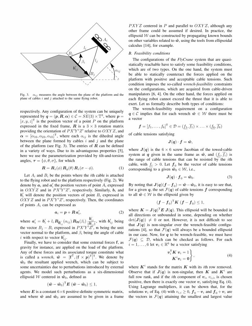
Fig. 3. αij measures the angle between the plane of the platform and theplane of cables i and j attached to the same flying robot.
respectively. Any configuration of the system can be uniquelyrepresented by q = (p,R,α) ∈ C = SE(3)×T3, where p =[x, y, z]T is the position vector of a point P on the platformexpressed in the fixed frame, R is a 3 × 3 rotation matrixproviding the orientation of PX ′Y ′Z ′ relative to OXY Z, andα = [α16, α23, α45]
T, where each αij is the dihedral anglebetween the plane formed by cables i and j and the planeof the platform (see Fig. 3). The entries of R can be definedin a variety of ways. Due to its advantageous properties [5],here we use the parameterization provided by tilt-and-torsionangles, τ = {φ, θ, σ}, for which
R = Rz(φ)Ry(θ)Rz(σ − φ). (1)
Let Ai and Bi be the points where the ith cable is attachedto the flying robot and to the platform respectively (Fig. 2). Wedenote by ai and a′i the position vectors of point Ai expressedin OXY Z and in PX ′Y ′Z ′, respectively. Similarly, bi andb′i will denote the position vectors of point Bi expressed inOXY Z and in PX ′Y ′Z ′, respectively. Then, the coordinatesof points Ai can be expressed as
ai = p+Ra′i, (2)
where a′i = b′i + liRb′ij(αij)Rn(βi)
b′ij
‖b′ij‖
, with b′ij being
the vector Bj − Bi expressed in PX ′Y ′Z ′, n being the unitvector normal to the platform, and βi being the angle of cablei with respect to vector b′ij .
Finally, we have to consider that some external forces f , asgravity for instance, are applied on the load of the platform.Any of these forces and its associated torque constitute whatis called a wrench, w = [fT, (f × p)T]T. We denote byw0 the resultant applied wrench, which can be subject tosome uncertainties due to perturbations introduced by externalagents. We model such perturbations as a six-dimensionalellipsoid W centered in w0, defined as
(w − w0)TE (w − w0) ≤ 1,
where E is a constant 6×6 positive-definite symmetric matrix,and where w and w0 are assumed to be given in a frame
PXY Z centered in P and parallel to OXY Z, although anyother frame could be assumed if desired. In practice, theellipsoid W can be constructed by propagating known boundson other variables related to w, using the tools from ellipsoidalcalculus [14], for example.
B. Feasibility conditions
The configurations of the FlyCrane system that are quasi-statically reachable have to satisfy some feasibility conditions,which are of two types. On the one hand, the system mustbe able to statically counteract the forces applied on theplatform with positive and acceptable cable tensions. Suchcondition imposes the so-called wrench-feasibility constraintson the configurations, which are acquired from cable-drivenmanipulators [6, 4]. On the other hand, the forces applied oneach flying robot cannot exceed the thrust that it is able toexert. Let us formally describe both types of conditions:
The wrench-feasibility requirement on a configurationq ∈ C implies that for each wrench w ∈ W there must bea vector
f = [f1, . . . , f6]T ∈ D = (f1, f1)× . . .× (f6, f6)
of cable tensions satisfying
J(q) · f = w,
where J(q) is the 6 × 6 screw Jacobian of the towed-cablesystem at q given in the same frame as w, and (fi, fi) isthe range of cable tensions that can be resisted by the ithcable, with fi > 0. Let f0 be the vector of cable tensionscorresponding to a given w0 ∈ W , i.e.,
J(q) · f0 = w0. (3)
By noting that J(q)(f −f0) = w− w0, it is easy to see that,for a given q, the set F(q) of cable tensions f correspondingto all w ∈ W is the ellipsoid given by
(f − f0)TK (f − f0) ≤ 1,
where K = J(q)TE J(q). This ellipsoid will be bounded inall directions or unbounded in some, depending on whetherdet(J(q)) 6= 0 or not. However, it is not difficult to seethat J(q) is non-singular over the wrench-feasible configu-rations [4], so that F(q) will always be a bounded ellipsoidin our case. Now, for q to be wrench-feasible, we must haveF(q) ⊆ D, which can be checked as follows. For eachi = 1, . . . , 6 let vi ∈ R6 be a vector satisfying
vTiK vi = 1
Kivi = 0
}, (4)
where Ki stands for the matrix K with its ith row removed.Observe that if J(q) is non-singular, then K and Ki arefull row rank, and if the ith component of vi, vi,i, is chosenpositive, then there is exactly one vector vi satisfying Eq. (4).Using Lagrange multipliers, it can be shown that, for thesolutions vi of Eq. (4) with vi,i ≥ 0, f0−vi and f0+vi arethe vectors in F(q) attaining the smallest and largest value
along the ith coordinate. Thus, for any configuration q, thetensions associated to the ith cable will take values betweenti(q) = f0,i − vi,i and ti(q) = f0,i + vi,i. Hence, whendet(J(q)) 6= 0, we have that F(q) ⊆ D if, and only if, fori = 1, . . . , 6
ti(q) > fi, (5)
andti(q) < fi. (6)
Then, the configurations satisfying the conditions ofEqs. (1)-(6) are able to equilibrate any external wrench in Wapplied on the platform ensuring that the cables will not betoo tight nor slack, i.e. are wrench-feasible.
As we said above, the thrust conditions also need to besatisfied. Clearly, each flying robot is subject to the forcesapplied by the attached cables i and j and its weight vectorgij , whose resultant should not exceed in norm the maximumthrust hij > 0 that the robot is able to exert. Now, ifui =
bi−ai
‖bi−ai‖is the unit vector associated to the ith cable,
then, in order to compensate the applied forces, each robotmust satisfy
where (λi, λj) ∈ [−vi,i, vi,i]× [−vj,j , vj,j ].All the previous conditions define the feasible configurations
that the aerial towed-cable system can reach, satisfying boththe wrench-feasibility and thrust constraints.
IV. PATH PLANNING STRATEGY
The current aim of the FlyCrane system is the 6-D quasi-static manipulation of a load. The resolution of such a manip-ulation problem can be seen as a path-planning query with theadditional feasibility constraints given in Section III-B. In fact,the required manipulation motion should also avoid solutionsthat may approach the violation of such constraints. With thisin mind, we will define a quality measure on the configurationsq of the system, given as a function c : C → R+, or costfunction.
Given two feasible configurations qinit and qgoal, classicalsampling-based path planners, such as the Rapidly-exploringRandom Tree (RRT) algorithm [11], aim at finding a collision-free, feasible path between them, but are not able to consider acontinuous cost function defined over the configuration space.Therefore, we cannot expect to obtain good-quality resultswith RRT. Instead, we will base our path-planning strategyon a variant of RRT, called the Transition-based RRT (T-RRT) algorithm [9], that takes this cost into account duringthe configuration-space exploration and that tends to producea good-quality path, i.e. a path following low-cost regions ofthe configuration space.
A. Quality measure
Let us first define the criteria that will characterize good-quality configurations, and the function to measure such qual-ity. The quality measure should evaluate whether a feasibleconfiguration is close to, or far from, non-feasible ones.
Therefore, a meaningful way to measure this quality relieson the fulfillment of the feasibility constraints provided inSection III, for which we will combine the conditions givenin Eqs. (5)-(7).
Given a configuration q, we define the cost of q, c(q), as
1∏ij (mij(q)− hij)
∏k
(tk(q)− fk
) (fk − tk(q)
) , (8)
where mij(q) is the maximum value of the left term of Eq. (7)associated to q. It is clear that c(q) > 0 on any feasibleconfiguration q. But whenever some cable tensions approachtheir limits or whenever the forces applied on some robotapproach the thrust of the robot, then c(q) tends to infinity.Actually, c(q) takes higher values when q gets closer to violateany of the conditions of Eqs. (5)-(7), which is the kind ofquality measure that we are looking for. Indeed, we will saythat qa is of better quality than qb if c(qa) < c(qb).
Appendix A shows that c(q) is a continuous differentiablefunction over the set of feasible configurations, which is acrucial property for the T-RRT planner to perform properly,because no abrupt cost changes are expected to occur. Itis important to add that while the path is computed inC = SE(3)×T3, it will have to be translated to the space R9
of quadrotor coordinates to be executed. Since the wrench-feasibility constraints are fulfilled all along the path, theJacobian J(q) of the system will never be singular on it,guaranteeing that the path in R9 will correspond to a uniquesmooth path in C. In other words, despite the system beingactuated by moving the quadrotors, its stiffness will never belost, because non-smoothnesses or path bifurcations will neverbe encountered.
Note finally that the lower-cost regions of C are veryfavorable to perform manipulation tasks, not only because theycorrespond to feasible regions, but also because they maintaina security margin from the configurations where constraintviolations occur (either the loss of tension, or the breakageof a cable, or a thrust insufficiency). Finding a path with lowcost values will thus be beneficial to properly maneuver of theFlyCrane system.
B. Transition-based RRT
The principle of RRT is to iteratively construct a tree thattends to rapidly expand on the configuration space, thanksto the implicit enforcement of a Voronoi bias [11]. At eachiteration of the tree construction, a configuration qrand israndomly sampled in C, and an expansion toward qrand isattempted, starting from its nearest neighbor in the tree, qnear,which potentially leads to the addition of a new configurationqnew to the tree. T-RRT extends RRT by integrating a stochas-tic transition test enabling it to steer the exploration towardlow-cost regions of the space. This transition test is basedon the Metropolis criterion typically used in Monte Carlooptimization methods [16]. These techniques aim at findingglobal minima in complex spaces and involve randomness asa means to avoid being trapped in local minima. Similarly,T-RRT uses a transition test to accept or reject a candidate
Algorithm 1: Transition-based RRTinput : the configuration space C
the cost function c : C → R+
the root configuration qinit
the goal configuration qgoal
output: the tree T1 T ← initTree(qinit)2 while not stopCondition(T , qgoal) do3 qrand ← sampleRandomConfiguration(C)4 qnear ← findNearestNeighbor(T , qrand)5 if refinementControl(T , qnear , qrand) then6 qnew ← extend(qnear , qrand)7 if qnew 6= null8 and transitionTest(T , c(qnear), c(qnew)) then9 addNewNodeAndEdge(T , qnear , qnew)
state, based on the cost variation associated with the localmotion from the previous state to this state. The pseudo-code of T-RRT (shown in Algorithm 1) is similar to that ofRRT [11], with the addition of the transitionTest andrefinementControl functions.
The transitionTest presented in Algorithm 2 is usedto evaluate the transition between the configurations qnear andqnew based on their respective costs. Three cases are possible:1) A new configuration whose cost is higher than the thresholdvalue cmax is automatically rejected. 2) A transition corre-sponding to a downhill move (cj ≤ ci) is always accepted. 3)Uphill transitions are accepted or rejected based on the proba-bility exp(−(cj−ci) / T ), which decreases exponentially withthe cost variation cj−ci, similarly to the Metropolis criterion.In that case, the level of difficulty of the transition test iscontrolled by the adaptive parameter T , called temperaturehere only by analogy to statistical physics. Low temperatureslimit the expansion to gentle slopes, and high temperaturesenable to climb steep slopes. The temperature is dynamicallytuned during the search process, which allows T-RRT toautomatically balance its bias toward low-cost regions with theVoronoi bias of RRT. After each accepted uphill transition, Tis decreased to avoid over-exploring high-cost regions: Moreprecisely, T is divided by 2(cj−ci) / (0.1 · costRange(T )), wherecostRange(T ) is the cost difference between the highest-cost configuration and the lowest-cost configuration present inthe tree T . After each rejected uphill transition, T is increasedto facilitate exploration and to avoid being trapped in a localminimum: More precisely, T is multiplied by 2Trate , whereTrate ∈ ]0, 1] is the temperature increase rate. In the rest of thepaper, we use Trate = 0.1 and we initialize T to 10−6. A valuecan be provided for cmax only when prior knowledge of theplanning problem is available and some regions of the spaceare forbidden. Note that, in the space where configurationswhose cost is greater than cmax are considered as part of theobstacle regions, T-RRT is probabilistically complete [9].
The adaptive temperature tuning of T-RRT ensures a givensuccess rate for uphill transitions, which can also con-tribute to refining the exploration of low-cost regions already
the current temperature Tthe temperature increase rate Trate
output: true if the transition is accepted, and false otherwise1 if cj > cmax then return False2 if cj ≤ ci then return True3 if exp(−(cj − ci) / T ) > 0.5 then4 T ← T / 2(cj−ci) / (0.1 · costRange(T ))
the refinement ratio ρoutput: true if refinement is not too high, and false otherwise
1 if distance(qnear, qrand) < δ2 and nbRefinementNodes(T ) > ρ · nbNodes(T ) then3 return False
4 return True
reached by the tree, as a side effect. The objective of therefinementControl function (shown in Algorithm 3) isto limit this refinement and facilitate the tree expansion towardunexplored regions. The idea is to reject an expansion thatwould lead to more refinement if the ratio of current refinementnodes with respect to the total number of nodes in the treeis greater than a certain value ρ, a refinement node beingdefined as a node whose distance to its parent is less than theextension step-size δ. Another benefit of the refinement controlis to limit the number of nodes in the tree and thus to reducethe computational cost of the neighbor search. Following thesuggestion in [9], we set ρ to 0.1.
V. TEST CASES
In this section, we evaluate the proposed approach ontwo 6-D quasi-static manipulation problems involving theFlyCrane system (cf. Fig. 1). The first example is a complextask (inspired by classical motion planning benchmarks) inwhich the FlyCrane has to get a 3-D puzzle piece through ahole, as illustrated by Fig. 4. The second example, presentedin Fig. 5, simulates a more realistic situation in which theFlyCrane has to install a lightweight footbridge between twobuildings to evacuate people during a rescue operation. Theseexamples differ in terms of difficulty: the Rescue problem isthe easiest one because it requires only a translation and tworotations about a single axis of the FlyCrane for a solutionto be found; the Puzzle problem requires to simultaneouslyperform a translation and four rotations about two axes ofthe FlyCrane. In both problems, the octahedral FlyCranewith an equilateral platform is considered. In our simulationenvironment, the cables are 2 m long, and the platform sidesare 1.4 m long.
Fig. 4. The Puzzle problem: the FlyCrane has to get a 3D puzzle piece through a hole.
Fig. 5. The Rescue problem: the FlyCrane has to install a lightweight footbridge between two buildings for a rescue operation.
TABLE IEVALUATION OF RRT AND T-RRT ON THE Puzzle AND Rescue PROBLEMS. AVERAGE VALUES OVER 100 RUNS ARE GIVEN FOR: THE AVERAGE COSTavgC , THE MAXIMAL COST maxC , THE MECHANICAL WORK MW , THE INTEGRAL OF THE COST IC , THE RUNNING TIME t (IN SECONDS), THE
NUMBER OF NODES N IN THE TREE, AND THE NUMBER OF EXPANSION ATTEMPTS X .
Puzzle RescueavgC maxC MW IC t (s) N X avgC maxC MW IC t (s) N X
On both examples, we evaluate the performance of the RRTand T-RRT algorithms on the basis of their running time t(in seconds), the number of attempted expansions X , and thenumber of nodes N in the produced tree. To avoid generatingtrivially-non-feasible paths, RRT only accepts feasible (i.e.collision-free and satisfying the aforementioned feasibilityconstraints) configurations. After performing a smoothing op-eration (based on the random shortcut method [8]) on the pathsgenerated by RRT and T-RRT, we evaluate the path quality bycomputing the average cost avgC, the maximal cost maxC,the mechanical work MW , and the integral of the cost IC.The mechanical work of a path is the sum of the positive costvariations along the path [9]. For all variables, we give valuesaveraged over 100 runs, as reported in Table I.
Unsurprisingly, Table I shows that T-RRT provides better-quality paths than RRT on both examples: on the Puzzle prob-lem, all cost statistics are more than one order of magnitudelower for paths generated by T-RRT; on the Rescue problem,they are between three and 50 times lower. Since it generallyrequires more expansion attempts to find configurations withacceptable cost, T-RRT is often slower than RRT, as is the caseon the Puzzle problem (169 s vs 34 s). However, it is worthnoting that T-RRT runs faster than RRT on the Rescue problem
(54 s vs 126 s), thanks to the lower number of nodes addedto the tree (379 vs 1361), which makes the nearest-neighborsearch faster.
We were interested in finding out what made path qualitydiffer between RRT and T-RRT. For that, we computed thetensions exerted on each cable and the forces exerted oneach quadrotor, along the paths produced by RRT and T-RRT, after dividing every path into 100 steps corresponding tointermediate configurations of the system. Then, for each path-step, we computed the minimal and maximal tensions (overall cables) and forces (over all quadrotors) over the 100 pathsproduced by RRT and over the 100 paths produced by T-RRT.Therefore, for each step, we obtained the tension ranges andthe force ranges yielded by RRT and T-RRT. Fig. 6 presentsthe profiles of the tension range and of the force range,respectively, on the Rescue problem. Similar plots have beenobtained on the Puzzle problem. We can see that using T-RRTleads to smaller tension and force ranges than using RRT. Mostimportantly, we observe that RRT produces paths along whicha tension or a force can be dangerously close to a bound of itsvalidity interval. For example, Fig. 6.a shows that, along somepath, at least one tension comes close to zero, meaning thatat least one cable almost goes slack. Similarly, on the Puzzle
Fig. 6. Profiles of a) the tension range and b) the force range, observed over 100 paths produced by RRT and T-RRT on the Rescue problem. The filledareas between the red curves represent the ranges for T-RRT; the areas between the green curves represent the ranges for RRT.
problem, one force comes close to the maximal thrust value.As a conclusion, we argue that integrating the path-planning T-RRT algorithm into the 6-D proposed manipulation approachallows us to plan safer paths for the FlyCrane system.
VI. CONCLUSION
We have presented an approach for the 6-dimensional quasi-static manipulation of a load with an aerial towed-cablesystem. The main contribution of the approach lies in thecombination of results deriving from the static analysis ofcable-driven manipulators with the application of a cost-basedmotion-planning algorithm to solve manipulation queries. Thelink underlying this combination is the definition of a qual-ity measure for the configurations of the system. First, thisquality measure is based on the wrench-feasibility constraintsapplied to cable-driven manipulators and on additional thrustconstraints, and allows: 1) to discriminate non-feasible fromfeasible configurations, and 2) to favor configurations that arefar from violating these constraints, by attributing them a lowcost. Second, this quality measure leads to the definition ofa cost function, thus allowing for the use of a cost-basedmotion-planning algorithm, namely the Transition-based RRT(T-RRT). As a result, rather than simply computing collision-free paths, the proposed approach produces good-quality paths,with respect to the constraints imposed on the system.
As part of our approach, we have additionally proposedan aerial towed-cable system that we have named the Fly-Crane. This system consists of a platform attached to threeflying robots by means of three pairs of fixed-length cables.We have evaluated the approach, in simulation, on two 6-D manipulation problems involving an octahedral version ofthe FlyCrane system. The results of the evaluation show thatthe proposed motion planning approach is suitable to solve6-D quasi-static manipulation tasks. Furthermore, they haveconfirmed that RRT, which is the original variant of T-RRTthat does not take the cost into account, may produce pathsthat occasionally approach dangerous situations, while T-RRTproduces safer paths.
The proposed approach allows for extensions in severalways. In particular, we expect to extend the method to considerpositioning errors for the flying robots, which could be due toexternal force perturbations and to errors in the localizationmethods. For this, similar techniques to those applied in thispaper could be used. Additionally, an interesing and challeng-ing extension to this work is the introduction of dynamics inthe motion of the load and of the flying robots, as they playan important role in the overall manipulation of the system.
In this paper, we have applied the proposed approach insimulated environments. As part of our future work, we planto implement this approach in a real aerial towed-cable system.This will serve as a testbed for the validation of the methodand its further extensions, providing relevant feedback on thereal limitations of the approach and the system. In real-lifesituations, the proposed approach could be helpful in variousapplications. As illustrated by the simulated Rescue problem,one possible application is the construction of platforms for theevacuation of people in rescue operations. Another applicationcould be the installation of platforms in uneven terrains for thelanding of manned or unmanned aircrafts. More generally, itcould be useful for the assembly of structures in places difficultto access for humans.
ACKNOWLEDGMENTS
This work has been partially supported and by the SpanishMinistry of Economy and Competitiveness under contractDPI2010-18449, by the European Community under contractICT 287617 “ARCAS”, and by a Juan de la Cierva contractsupporting the first author.
REFERENCES
[1] J. Albus, R. Bostelman, and N. Dagalakis. The NISTRobocrane. J. Robotic Systems, 10(5):709–724, 1993.
[2] D. Berenson, T. Simeon, and S. Srinivasa. AddressingCost-Space Chasms in Manipulation Planning. In IEEEInt. Conf. Robotics and Automation, pages 4561–4568,2011.
[3] M. Bernard, K. Kondak, I. Maza, and A. Ollero. Au-tonomous transportation and deployment with aerialrobots for search and rescue missions. J. Field Robotics,28(6):914–931, 2011.
[4] O. Bohigas, M. Manubens, and L. Ros. Navigating theWrench-Feasible C-Space of Cable-Driven Hexapods. InCable-Driven Parallel Robots, pages 53–68. Springer,2012.
[5] I.A. Bonev, D. Zlatanov, and C.M. Gosselin. Advantagesof the modified Euler angles in the design and control ofPKMs. In Parallel Kinematic Machines Int. Conf., pages171–188, 2002.
[6] P. Bosscher, A.T. Riechel, and I. Ebert-Uphoff. Wrench-feasible workspace generation for cable-driven robots.IEEE Trans. Robotics, 22(5):890–902, 2006.
[7] J. Fink, N. Michael, S. Kim, and V. Kumar. Planning andcontrol for cooperative manipulation and transportationwith aerial robots. Int. J. Robotics Research, 30(3):324–334, 2011.
[8] R. Geraerts and M. H. Overmars. Creating high-qualitypaths for motion planning. Int. J. Robotics Research, 26(8):845–863, 2007.
[9] L. Jaillet, J. Cortes, and T. Simeon. Sampling-based pathplanning on configuration-space costmaps. IEEE Trans.Robotics, 26(4):635–646, 2010.
[10] L. Jaillet, F.J. Corcho, J.J. Perez, and J. Cortes. Ran-domized tree construction algorithm to explore energylandscapes. J. Computational Chemistry, 32(16):3464–3474, 2011.
[11] S. M. LaValle and J. J. Kuffner. Rapidly-exploringrandom trees: Progress and prospects. In Algorithmic andComputational Robotics: New Directions, pages 293–308. A K Peters, 2001.
[12] N. Michael, J. Fink, and V. Kumar. Cooperative manipu-lation and transportation with aerial robots. AutonomousRobots, 30(1):73–86, 2011.
[13] R. M. Murray. Trajectory Generation for a Towed CableSystem Using Differential Flatness. In IFAC WorldCongress, 1996.
[14] L. Ros, A. Sabater, and F. Thomas. An ellipsoidal calcu-lus based on propagation and fusion. IEEE Transactionson Systems, Man, and Cybernetics, Part B: Cybernetics,32(4):430–442, 2002.
[15] R. A. Skop and Y. I. Choo. The Configuration of a CableTowed in a Circular Path. J. Aircraft, 8:856–862, 1971.
[16] J.C. Spall. Introduction to Stochastic Search and Op-timization: Estimation, Simulation, and Control. Wiley,2003.
[17] A. Steltzner, D. Kipp, A. Chen, D. Burkhart,C. Guernsey, G. Mendeck, R. Mitcheltree, R. Powell,T. Rivellini, M. San Martin, and D. Way. Mars ScienceLaboratory entry, descent, and landing system. In IEEEAerospace Conf., 2006.
[18] P. Williams. Optimal terrain-following for towed-aerial-cable sensors. Multibody System Dynamics, 16(4):351–374, 2006.
APPENDIX
Let us prove that the cost c(q), as defined in Sec. IV-A, isa continuously differentiable function c : C → R+. Note thatc(q) can be equivalently determined as the solution c > 0 of
c∏ij
(mij(q)− hij)∏k
(tk(q)− fk)(fk − tk(q)) = 1. (9)
We can now define a system of polynomial equations formedby Eqs. (1)-(4), and Eq. (9), which we write as
F (x) = 0, (10)
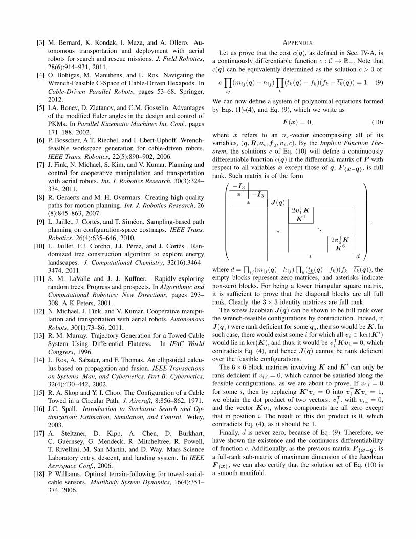
where x refers to an nx-vector encompassing all of itsvariables, (q,R,ai,f0,vi, c). By the Implicit Function The-orem, the solutions c of Eq. (10) will define a continuouslydifferentiable function c(q) if the differential matrix of F withrespect to all variables x except those of q, F {x−q}, is fullrank. Such matrix is of the form
−I3∗ −I3∗ J(q)
2vT1KK1
∗. . .
2vT6KK6
∗ d
,
where d =∏
ij(mij(q)−hij)∏
k(tk(q)−fk)(fk−tk(q)), theempty blocks represent zero-matrices, and asterisks indicatenon-zero blocks. For being a lower triangular square matrix,it is sufficient to prove that the diagonal blocks are all fullrank. Clearly, the 3× 3 identity matrices are full rank.
The screw Jacobian J(q) can be shown to be full rank overthe wrench-feasible configurations by contradiction. Indeed, ifJ(qs) were rank deficient for some qs, then so would beK. Insuch case, there would exist some i for which all vi ∈ ker(Ki)would lie in ker(K), and thus, it would be vTiKvi = 0, whichcontradicts Eq. (4), and hence J(q) cannot be rank deficientover the feasible configurations.
The 6× 6 block matrices involving K and Ki can only berank deficient if vi,i = 0, which cannot be satisfied along thefeasible configurations, as we are about to prove. If vi,i = 0for some i, then by replacing Kivi = 0 into vTiKvi = 1,we obtain the dot product of two vectors: vTi , with vi,i = 0,and the vector Kvi, whose components are all zero exceptthat in position i. The result of this dot product is 0, whichcontradicts Eq. (4), as it should be 1.
Finally, d is never zero, because of Eq. (9). Therefore, wehave shown the existence and the continuous differentiabilityof function c. Additionally, as the previous matrix F {x−q} isa full-rank sub-matrix of maximum dimension of the JacobianF {x}, we can also certify that the solution set of Eq. (10) isa smooth manifold.