26
Motion Transmission Systems Technology continued...
| Date post: | 24-Dec-2015 |
| Category: |
Documents |
| Upload: | jordan-harrell |
| View: | 215 times |
| Download: | 0 times |
Motion Transmission Systems
Technology continued...
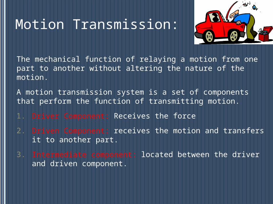
Motion Transmission:
The mechanical function of relaying a motion from one part to another without altering the nature of the motion.
A motion transmission system is a set of components that perform the function of transmitting motion.
1. Driver Component: Receives the force
2. Driven Component: receives the motion and transfers it to another part.
3. Intermediate component: located between the driver and driven component.

Driver Component
Intermediate Component
Driven Component
Characteristics of Motion in TS
In mechanical engineering, motion transmission systems are often applied to technical objects. The most common systems are:
1. Gear trains systems
2. Chain and sprocket systems
3. Worm and worm gear systems
4. Friction gear systems
5. Belt and pulley systems
Characteristics of TS All transmit rotational motion
The direction of the rotation of the components may be identical throughout or different.
• Clockwise or counter clockwise
The system may or may not be reversible.
• If it is reversible then the driven component can become a driver and vice versa.

Gears
Gears are generally used for one of four different reasons:
• To reverse the direction of rotation
• To increase or decrease the speed of rotation
• To move rotational motion to a different axis
• To keep the rotation of two axis synchronized
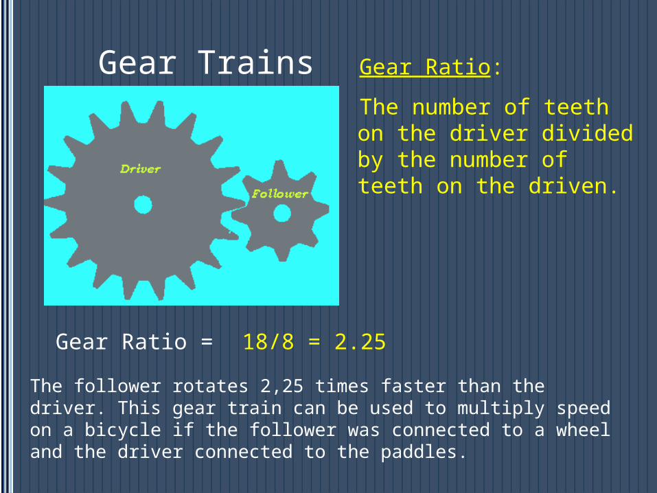
Gear Trains Gear Ratio:
The number of teeth on the driver divided by the number of teeth on the driven.
The follower rotates 2,25 times faster than the driver. This gear train can be used to multiply speed on a bicycle if the follower was connected to a wheel and the driver connected to the paddles.
Gear Ratio = 18/8 = 2.25

Small gear= more turns= faster speedBigger gears= less turns= slower speed.
Gear Ratio:
Gear Ratio:
1/1
9/4

Plenary Gear SystemIn this gear system, the yellow gear engages all three red gears simultaneously. They are all three attached to a plate, and they engage the inside of the blue gear instead of the outside. Because there are three red gears instead of one, this gear train is extremely rugged.

If you have two gears that you want to keep synchronized but some distance apart, What could you do?
1) Add a gear between them:
2) Add a chain

The gears are no longer touching, they are now called sprockets.
Chain and Sprocket

Worm GearsWorm gears are used when large gear reductions are needed. It is common for worm gears to have reductions of 20:1, and even up to 300:1 or greater.
Worm gear
The worm is the driver. The opposite will not work.
• For each 360° turn of the worm, the worm-gear advances only one tooth of the gear.
Worm
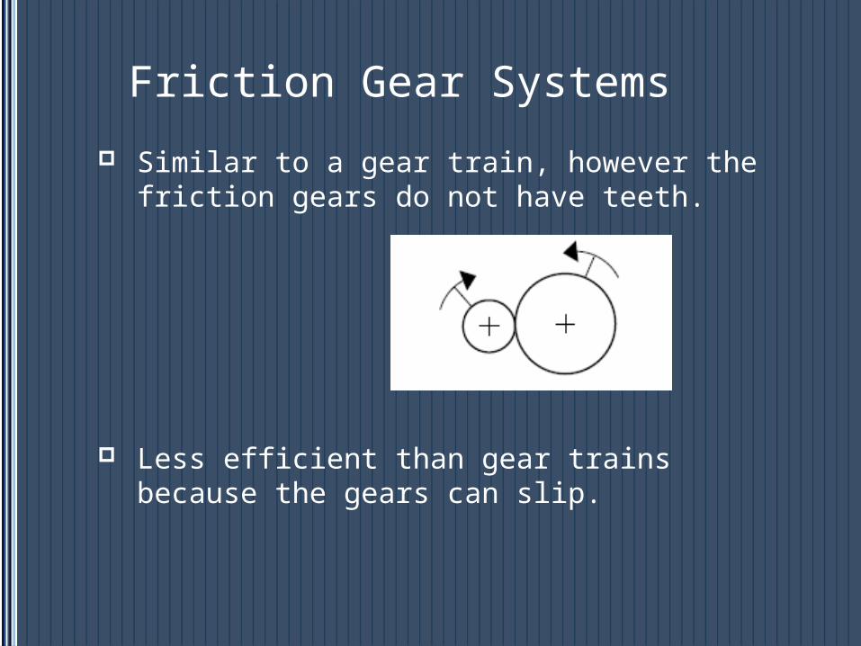
Friction Gear Systems
Similar to a gear train, however the friction gears do not have teeth.
Less efficient than gear trains because the gears can slip.

Belt and Pulley System
Similar to a chain and sprocket however, there are no teeth.
The gear without teeth is called the pulley.
The chain is called the belt.

Speed Changes
A speed change occurs in a motion transmission system when the driver does not turn at the same speed as the driven component or components.

Speed ChangesSpeed Change Friction gear or belt
and pulleyGear trains or chain and sprocket
Increase Motion is transmitted to a gear or pulley of smaller diameter
Motion is transmitted from one gear or sprocket to another with fewer teeth.
Decrease Motion is transmitted to a gear or pulley of larger diameter
Motion is transmitted from one gear or sprocket to another with more teeth.
No change Motion is transmitted to a gear or pulley with the same diameter.
Motion is transmitted from one gear or sprocket to another with the same number of teeth.

Characteristics of Motion in Transformation Systems
Mechanical action that changes the nature of motion (rotation to translation, translation to rotation)
1) Rack and pinion

Rack and Pinion Systems
Must contain at least 1 gear (pinion) and one straight bar with teeth (rack)
Elements to consider
Teeth must be identical
Requires frequent lubrication
Greater amount of teeth the slower its rotation
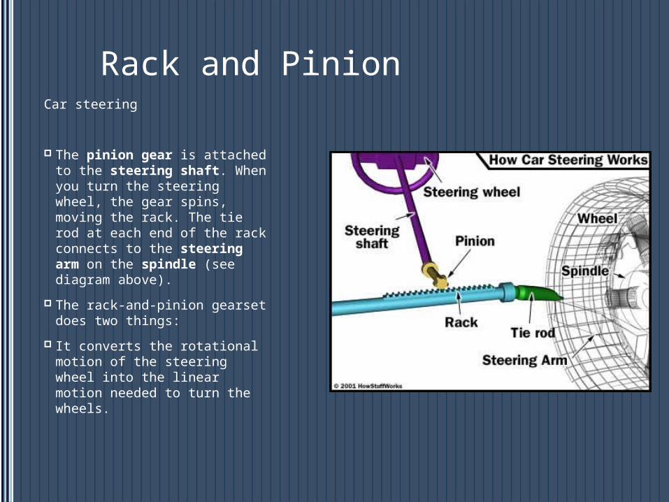
Rack and PinionCar steering
The pinion gear is attached to the steering shaft. When you turn the steering wheel, the gear spins, moving the rack. The tie rod at each end of the rack connects to the steering arm on the spindle (see diagram above).
The rack-and-pinion gearset does two things:
It converts the rotational motion of the steering wheel into the linear motion needed to turn the wheels.

2) Screw Gear System
Rotation causes a translation

Screw Gear Systems
Elements to consider
Type 1- the nut must be connected to the screw in such a way that the nut cannot rotate
In both- the threads of the screws and nuts must match
Type 2- nut must be fixed so that the only possible motion is rotation
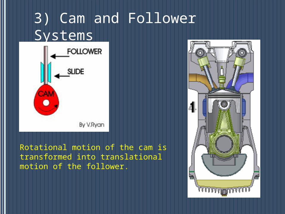
3) Cam and Follower Systems
Rotational motion of the cam is transformed into translational motion of the follower.

Cam and follower
Elements to consider
The follower must be guided in translational motion
Shape of cam determines how the follower will move
A spring is usually required to keep follower in contact with cam
http://www.ul.ie/~kirwanp/whatisacamandfollowersyste.htm

4) Slider-Crank Mechanism
Translational motion of the piston is transformed into rotational motion of the crank.
piston
Crank
Connecting rod
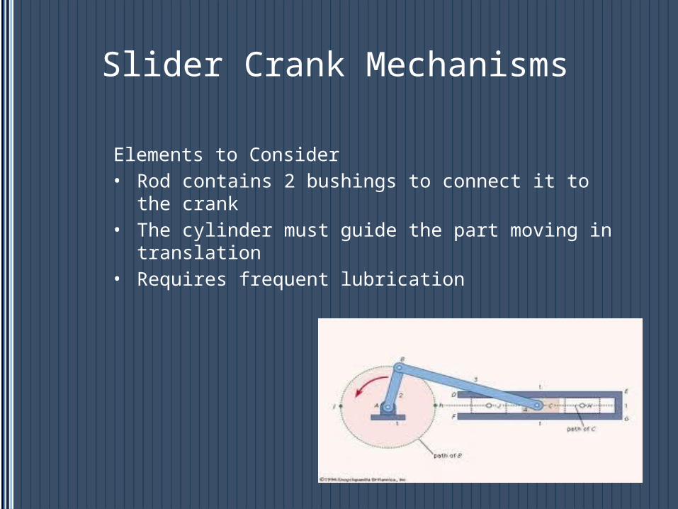
Slider Crank Mechanisms
Elements to Consider• Rod contains 2 bushings to connect it to the crank• The cylinder must guide the part moving in
translation• Requires frequent lubrication