11
APEX DYNAMICS, INC. HIGH PRECISION PLANETARY GEARBOXES

APEX DYNAMICS, INC.
HIGH PRECISION PLANETARY GEARBOXES
AB SeriesAB Series
ABR090 010 P1- -
Gearbox Size:
ABR042, ABR060, ABR090
ABR115, ABR142, ABR180,
ABR220
Shaft Option:
S1: Smooth Output Shaft
S2: Output Shaft with Key
Ratio:
1 Stage: 3, 4, 5, 6, 7, 8, 9, 10, 14, 20
2 Stage: 15, 20, 25, 30, 35, 40, 45, 50, 60, 70,
80, 90, 100, 120, 140, 160, 180, 200
Backlash:
P0: Micro Backlash
P1: Reduced Backlash
P2: Standard Backlash
S1- MOTOR/
AB090 010 P1- -
Gearbox Size:
AB042, AB060, AB060A, AB090, AB090A
AB115, AB142, AB180, AB220
S1- MOTOR/
Ordering Example: ABR090-010-S1-P1 / SIEMENS 1FT6 041-4AF71
ABR SeriesABR Series
Please visit our website for newest update data.
Ordering Example: AB090-010-S1-P1 / SIEMENS 1FT6 041-4AF71
Ordering Code
Shaft Option:
S1: Smooth Output Shaft
S2: Output Shaft with Key
Ratio:
1 Stage: 3, 4, 5, 6, 7, 8, 9, 10
2 Stage: 15, 20, 25, 30, 35, 40, 45, 50, 60, 70,
80, 90, 100
Backlash:
P0: Micro Backlash
P1: Reduced Backlash
P2: Standard Backlash
Motor Designation:
Manufacturer Type
And Model
Motor Designation:
Manufacturer Type
And Model
No.10, Keyuan 3rd Rd., Situn District, Taichung City 407, Taiwan (R.O.C.)
Tel: 886 4 23550219 / Fax: 886 4 23550218
E-mail: [email protected]
Website: www.apexdyna.com
APEX DYNAMICS, INC.
APEX-2011-12-AB / ABA / ABR-2.0E-3.3V
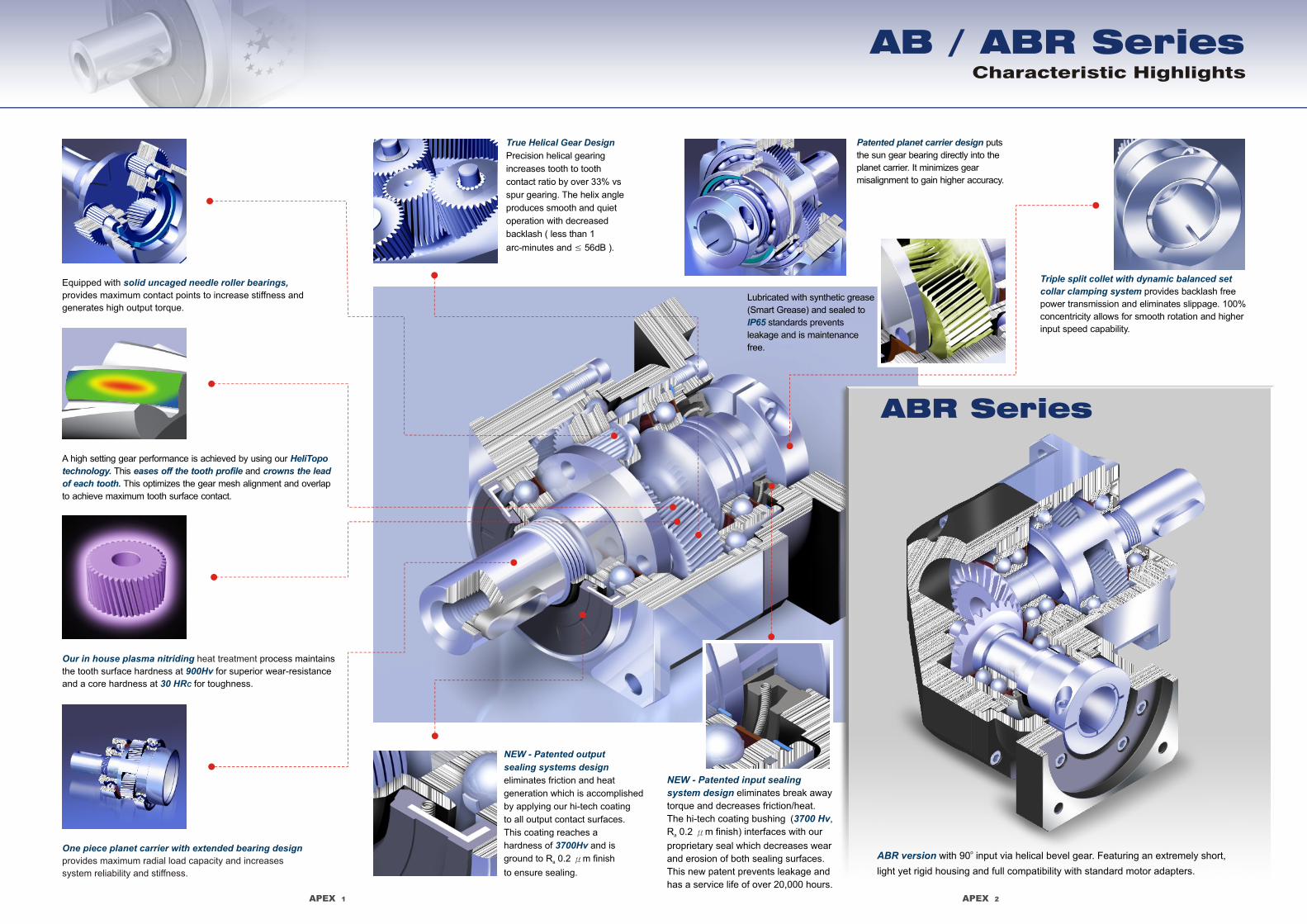
Equipped with
provides maximum contact points to increase stiffness and
generates high output torque.
solid uncaged needle roller bearings,
One piece planet carrier with extended bearing design
provides maximum radial load capacity and increases
system reliability and stiffness.
Our in house plasma nitriding
900Hv
30 HRC
heat treatment process maintains
the tooth surface hardness at for superior wear-resistance
and a core hardness at for toughness.
A high setting gear performance is achieved by using our
This and
This optimizes the gear mesh alignment and overlap
to achieve maximum tooth surface contact.
HeliTopo
technology. eases off the tooth profile crowns the lead
of each tooth.
Triple split collet with dynamic balanced set
collar clamping system provides backlash free
power transmission and eliminates slippage. 100%
concentricity allows for smooth rotation and higher
input speed capability.
True Helical Gear Design
Precision helical gearing
increases tooth to tooth
contact ratio by over 33% vs
spur gearing. The helix angle
produces smooth and quiet
operation with decreased
backlash ( less than 1
arc-minutes and ≤ 56dB ).
Patented planet carrier design puts
the sun gear bearing directly into the
planet carrier. It minimizes gear
misalignment to gain higher accuracy.
NEW - Patented output
sealing systems design
3700Hv
eliminates friction and heat
generation which is accomplished
by applying our hi-tech coating
to all output contact surfaces.
This coating reaches a
hardness of and is
ground to R 0 2 m finish a
to ensure sealing.
. μ
Characteristic Highlights
AB / ABR Series
Lubricated with synthetic grease
(Smart Grease) and sealed to
standards prevents
leakage and is maintenance
free.
IP65
APEX 1
NEW - Patented input sealing
system design
3700 Hv
eliminates break away
torque and decreases friction/heat.
The hi-tech coating bushing ( ,
R 0.2 m finish) interfaces with our a
proprietary seal which decreases wear
and erosion of both sealing surfaces.
This new patent prevents leakage and
has a service life of over 20,000 hours.
μ
APEX 2
ABR Series
ABR version o with 90 input via helical bevel gear. Featuring an extremely short,
light yet rigid housing and full compatibility with standard motor adapters.

AB042 AB060 AB090 AB115 AB142 AB180 AB220Stage AB060A AB090A
APEX 3 APEX 4
Specifications
AB SeriesDimensions (1-stage, Ratio i=3~10)
0.030.030.030.030.030.030.030.030.030.030.030.030.030.030.030.030.030.030.030.030.03
0.160.140.130.130.130.130.130.130.030.030.030.030.030.030.030.030.030.030.030.030.03
0.61
0.480.470.450.450.440.440.440.130.130.130.130.130.130.130.130.130.130.130.130.130.130.130.130.130.130.130.130.130.130.130.130.130.13
3.25
2.742.712.652.622.582.572.570.470.470.470.470.470.470.470.470.470.470.470.470.470.470.440.440.440.440.440.440.440.440.440.440.440.44
9.217.547.427.257.147.077.047.032.712.712.712.712.712.712.712.572.572.572.572.572.57
28.9823.6723.2922.7522.4822.5922.5322.517.427.427.427.427.427.427.427.037.037.037.037.037.03
54.3753.2751.7250.9750.8450.6350.5623.2923.2923.2923.2923.2923.2923.2922.5122.5122.5122.5122.5122.51
69.61
1
3456789
10152025303540455060708090
100
Gearbox InertiaModel No.
2kg‧cmMass Moments of Inertia J1
Gearbox Performance
1. Ratio ( i=N / N )in out 3. Applied to the output shaft center @ 100 rpm
5,00010,000
≤5
≤73
780390
0.60.8
5,00010,000
71,530765
1.31.5
4,000 4,0008,000 8,000
14 143,250 3,2501,625 1,625
3.74.1
4,0008,000
256,7003,350
≥97%≥94%
7.89
3,0006,000
509,4004,700
14.517.5
3,0006,000
14514,5007,250
2933
2,0004,000
22550,00025,000
4860
20,000
≤1≤3
≤56 ≤58 ≤60 ≤63 ≤63 ≤65 ≤67 ≤70
AB042 AB060 AB090 AB115 AB142 AB180 AB220
1
2
1,21,21,2
1212
1,21,21,21,21212
1,2
1,21,21,2
12
IP65
Model No.
Nominal Output Torque T2N Nm
Degree of Gearbox Protection
Nmrpmrpm
Nominal Input Speed n1N
Max. Input Speed n1B
Reduced Backlash P1
Micro Backlash P0
arcminStandard Backlash P2
arcmin
arcmin
NNhr
Nm/arcminTorsional Rigidity
Service Life
Efficiency
Weight
%
kg
Operating Temp
Lubrication
Mounting Position
Noise Level (n =3000rpm, No Load)1 dB(A)
Max. Radial Load F2rB3
Max. Axial Load F2aB3
3 times of Nominal Output Torque
all directions
Stage
*
1922201917141420192220191714222019171414
5060555045404055506055504540605550454040
140160150140120100100130 130140 140160 160150 150140 140120 120100 100160 160150 150140 140120 120100 100100 100
290330310300260230230208290330310300260230330310300260230230
542650600550500450450342542650600550500450650600550500450450
1,0501,2001,1001,1001,000900900588
1,0501,2001,1001,1001,000900
1,2001,1001,1001,000900900
1,7002,0001,9001,8001,6001,5001,5001,1401,7002,0001,9001,8001,6001,5002,0001,9001,8001,6001,5001,500
20 55 130 208 342 588 1,140
3~1003~1003~100
3~1015~100
3~1015~100
3~1003~1003~1003~1003~10
15~1003~10
15~1003~100
3~1003~1003~100
3~1015~100
Ratio1
456789
10152025303540455060708090
100
3
AB042 AB060 AB142 AB180 AB220AB090 AB115
D1
D2
D3 j6
D4 g6
D5
D6
D7
L1
L2
L3
L4
L5
L6
L7
L9
L8
L10
50
3.4
13
35
22
M4 x 0.7P
56
42
26
5.5
1
16
2
4
4.5
31
10
46
M4 x 0.7P
25
30
3.5
42
29.5
86.5
8.75
5
15
70
5.5
16
50
45
60
37
7
1.5
25
2
6
4.8
61
12.5
70
M5 x 0.8P
34
50
8
60
19
117
13.5
5
18
165
11
40
130
75
142
97
15
3
63
5
12
12
119.5
36
165
M10 x 1.5P
60
130
6
142
22.5
239
15
12
43
215
13
55
160
95
180
105
20
3
70
6
15
15
154
42
215
M12 x 1.75P
85
180
6
190
29
288
20.75
16
59
250
17
75
180
115
220
138
30
3
90
7
20
15
163.5
42
235
M12 x 1.75P
116
200
6
220
63
364.5
53
20
79.5
C14
C24
C44
C54
C64
C74
C84
C94
C104
B1 h9
H1
130
9
32
110
95
115
65
12
2
40
5
10
10
102
28
130
M8 x 1.25P
50
110
5
115
19.5
186.5
13
10
35
100
6.6
22
80
65
90
48
10
1.5
32
3
8
7.2
78.5
19
100
M6 x 1P
40
80
4
90
17
143.5
10.75
6
24.5
C34 ≤32 ≤38 ≤48 ≤55≤19 / ≤24
M5 x 0.8P
80
M8 x 1.25P
116
M12 x 1.75P
152
M16 x 2P
185
M20 x 2.5P
240
M20 x 2.5P
292
[unit: mm]
Dimension
4. C1~C10 are motor specific dimensions (metric std shown). Refer to Apexdyna.com and Design Tool to view your specific motor mounting system.
AB042 ratio 5, 10 offers C3 ≤ 12 option.
≤1 ≤1 ≤1 ≤1≤3 ≤3 ≤3≤3 ≤3 ≤3≤3≤3≤3≤3
≤5 ≤5 ≤5 ≤5 ≤5 ≤5 ≤5
≤7≤5 ≤5 ≤5 ≤5 ≤5 ≤5 ≤5
≤7 ≤7 ≤7 ≤7 ≤7 ≤7
2
S1 service life 10,000 hrs (Consult us)
AB060A AB090A
5,00010,000
71,530765
1.9 5.3
55506055504540605550454040
≤5
≤7
Ratio1
H1
B1 h9
D6
ØD3 j6
L9
L5L6
L10
Shaft Option S1 Shaft Option S2
L2
ØD
5
ØD
4g
6
L8 C8
C9
ØD2 C2L4
ØC
3
ØC
5
C6
C4L7
45°
45°
45°
45°
L3 C10
ØD
1
ØC
1
L1
ØD7
C7
NmEmergency Stop Torque T2NOT2
2. Max. acceleration torque T = 60% of T2B 2NOT
≤14 / ≤16
Synthetic lubrication oils
≤11 / ≤12
AB060 ratio 5, 10 offers C3 ≤ 16 option.
o o-10 C~90 C

C15 46 46 70 100 130
C35
C45 25 25 34 40
C55 30 30 50 80
C65 3.5 3.5 8 4
C75 42 42 60 90
C85 29.5 29.5 19 17
C95 114 138.5 178.5 225.5
C105 8.75 8.75 13.5 10.75
B1 h9 5 5 6 10
H1 15 18 24.5 35
≤32
50
110
5
115
19.5
292.5
13
12
43
50 70 100 130 165D1
3.4 5.5 6.6 9 11D2
13 16 22 32 40D3 j6
35 50 80 110 130D4 g6
22 45 65 95 75D5
D6
42 60 90 115 142L1
26 37 48 65 97L2
5.5 7 10 12 15L3
1 1.5 1.5 2 3L4
16 25 32 40 63L5
2 2 3 5 5L6
4 6 8 10 12L7
58.5
4.5
10
72
4.8
12.5
111.5
7.2
19
143.5
10
28
176
12
36
L8
L9
L10
C25 M4 x 0.7P M5 x 0.8P M6 x 1P M12 x 1.75PM4 x 0.7P M8 x 1.25P
≤11 / ≤12 ≤19 / ≤24 ≤14 / ≤15.875 / ≤16
165
≤38
60
130
6
142
22.5
337
15
16
59
215
13
55
160
95
180
105
20
3
70
6
15
209.5
15
42
M10 x 1.5P
215
≤48
85
180
6
190
29
415
20.75
20
79.5
250
17
75
180
115
220
138
30
3
90
7
20
248
15
42
M4 x 0.7P M5 x 0.8P M8 x 1.25P M12 x 1.75P M16 x 2P M20 x 2.5P
D7 56 80 116 152 185 240 292
AB042 AB060 AB090 AB115 AB142 AB180 AB220
[unit: mm]
Dimension
5. C1~C10 are motor specific dimensions (metric std shown). Refer to Apexdyna.com and Design Tool to view your specific motor mounting system.
APEX 5 APEX 6
AB SeriesDimensions (2-stage, Ratio i=15~100) Specifications
ABR Series
Gearbox Performance
arcmin
arcmin
%
kg
arcmin
Model No.
NmNominal Output Torque T2N
Reduced Backlash P1
Micro Backlash P0
Standard Backlash P2
Efficiency
Weight
Mounting Position
NMax. Radial Load F2rB
3
ABR042 ABR060 ABR090 ABR115 ABR142 ABR180 ABR220
9
12
15
18
19
17
15
20
19
17
14
14
20
19
17
14
36
48
60
55
50
45
90
120
150
150
140
120
195
260
325
310
300
342
520
650
600
550
500
588
1,040
1,200
1,100
1,100
1,000
1,140
1,680
2,000
1,900
1,800
1,600
all directions
60
55
50
45
40
60
55
50
45
40
150
150
140
120
100
100
150
140
120
100
120
325
310
300
260
230
230
310
300
260
230
260
650
600
550
500
450
650
600
550
500
450
550
1,200
1,100
1,100
1,000
900
1,200
1,100
1,100
1,000
900
1,000
2,000
1,900
1,800
1,600
1,500
2,000
1,900
1,800
1,600
1,500
1,600
780 1,530 3,250 6,700 9,400 14,500 50,000
3
4
5
6
7
8
14 40 100
260
450 900 1,5009
14 40 100
230
450 900 1,50010
3~200
42 140 300 550 1,100 1,80014
1420
25
30
35
40
45
50
60
70
80
90
14 40 100 230 450 900 1,500100
150 310 600 1,100 1,900120
140 300 550 1,100 1,800140
160
100 230 450 900 1,500180
100 230 450 900 1,500200
3~200
1
2
Nm 3 times of Nominal Output Torque3~2001,2rpmNominal Input Speed n1N 5,000 5,000 4,000 4,000 3,000 3,000 2,0003~2001,2rpmMax. Input Speed n1B 10,000 10,000 8,000 8,000 6,000 6,000 4,0003~2001,2
≤4 ≤4 ≤4 ≤4 ≤4≤4 ≤43~201
≤7 ≤7 ≤7 ≤7 ≤7 ≤7≤725~2002
≤6 ≤6 ≤6 ≤6 ≤6 ≤6 ≤63~201
≤9 ≤9 ≤9 ≤9 ≤9 ≤9 ≤925~2002
Nm/arcminTorsional Rigidity 3 7 14 25 50 145 2253~2001,2
NMax. Axial Load F2aB
3390 765 1,625 3,350 4,700 7,250 25,0003~2001,2
≥95%3~201
≥92%25~2002
0.9 2.1 6.4 13 24.5 51 833~201
1.2 1.5 7.8 14.2 27.5 54 9525~2002oCOperating Temp o o-10 C~+90 C3~2001,2
Lubrication
Degree of Gearbox Protection IP653~2001,2
1,2
≤2 ≤2 ≤2 ≤2 ≤23~201
≤4 ≤4 ≤4 ≤4≤425~2002
Stage
1,2
≤61 ≤63 ≤65 ≤68 ≤70 ≤72 ≤743~2001,2
Ratio1
hrService Life 3~2001,2 20,000*
1415
0.090.090.09 0.09 0.35 2.25 6.84 23.4 68.9
1
2kg‧cm
Gearbox Inertia
Mass Moments of Inertia J1
ABR042 ABR060 ABR090 ABR115 ABR142 ABR180 ABR220Model No. Stage
0.09 0.35 2.25 6.84 23.4 68.9 135.43~10
1520
25~100
Ratio1
0.07 1.87 6.25 21.8 65.6 119.814
0.31 1.87 6.25 21.8 65.6120~200
40 100 230 450 900 1,50020
0.07 1.87 6.25 21.8 65.6 119.820
2
AB060A
98
70
M5 x 0.8P
≤14 / ≤16
126.5
100
M6 x 1P
34
50
8
60
19
154
13.5
40
80
4
90
17
191.5
10.75
AB090A
M20 x 2.5P
230
L9
L5L6
L10
Shaft Option S1 Shaft Option S2
H1
B1 h9
D6
ØD3 j6
L1
ØD7
ØD
1
o
45
o45
ØD
4 g
6
ØD
5
L3
L2 L8 C8
C9
C10
ØC
3
ØC
5
C4
C6L4
L7
C7
ØC
1C2
o
45
o45
ØD2
AB060A / AB090A
C2
45°
45°
ØC
1
L3
L2 L8 C8
C4
ØD
5
ØD
4g
6
L4
C9
ØC
3
ØC
5
C6
L7
C10C7
Emergency Stop Torque T2NOT
2
Noise Level (n =3000rpm, No Load)1 dB(A)
1. Ratio ( i=N / N )in out 3. Applied to the output shaft center @ 100 rpm2. Max. acceleration torque T = 60% of T2B 2NOT
S1 service life 10,000 hrs (Consult us)
Synthetic lubrication oils
≤11 / ≤12 ≤19 / ≤24

APEX 7 APEX 8
Dimensions (1-stage, Ratio i=3~20) Dimensions (2-stage, Ratio i=15~200)
ABR Series
D1
D2
D5
L1
L2
L3
L4
L5
L6
L7
L8
ABR042 ABR060 ABR142 ABR180 ABR220
50
3.4
13
35
22
42
26
5.5
1
16
2
4
111.5
25
30
3.5
42
29.5
90.5
8.75
5
15
70
5.5
16
50
45
60
37
7
1.5
25
2
6
145
34
50
8
60
19
111.5
13.5
5
18
165
11
40
130
75
142
97
15
3
63
5
12
333
60
130
6
142
22.5
235.5
15
12
43
215
13
55
160
95
180
105
20
3
70
6
15
394
85
180
6
190
29
303.5
20.75
16
59
250
17
75
180
115
220
138
30
3
90
7
20
484
116
200
6
220
63
378.5
53
20
79.5
ABR090 ABR115
130
9
32
110
95
115
65
12
2
40
5
10
259
50
110
5
115
19.5
191.5
13
10
35
100
6.6
22
80
65
90
48
10
1.5
32
3
8
203
40
80
4
90
17
152.5
10.75
6
24.5
D3 j6
D4 g6
46 70 165 215 235130100C14
M4 x 0.7P M5 x 0.8P M10 x 1.5P M12 x 1.75P M12 x 1.75PM8 x 1.25PM6 x 1PC24
C44
C54
C64
C74
C84
C94
C104
B1 h9
H1
[unit: mm]
Dimension ABR042 ABR060 ABR142 ABR180 ABR220ABR090 ABR115
50
3.4
13
35
22
42
26
5.5
1
16
2
4
139
46
M4 x 0.7P
25
30
3.5
42
29.5
90.5
8.75
5
15
100
6.6
22
80
65
90
48
10
1.5
32
3
8
206.5
70
M5 x 0.8P
34
50
8
60
19
126.5
13.5
6
24.5
130
9
32
110
95
115
65
12
2
40
5
10
285
100
M6 x 1P
40
80
4
90
17
165
10.75
10
35
165
11
40
130
75
142
97
15
3
63
5
12
365
130
M8 x 1.25P
50
110
5
115
19.5
205
13
12
43
215
13
55
160
95
180
105
20
3
70
6
15
431
165
M10 x 1.5P
60
130
6
142
22.5
254.5
15
16
59
250
17
75
180
115
220
138
30
3
90
7
20
521
215
M12 x 1.75P
85
180
6
190
29
323.5
20.75
20
79.5
70
5.5
16
50
45
60
37
7
1.5
25
2
6
163.5
46
M4 x 0.7P
25
99.5
5
18
30
3.5
42
29.5
8.75
D1
D2
D5
L1
L2
L3
L4
L5
L6
L7
L8
C15
C45
C55
C65
C75
C85
C95
C105
B1 h9
H1
C25
D3 j6
D4 g6
Dimension
≤38 ≤48 ≤55≤32C34 ≤19 / ≤24 ≤32 ≤38 ≤48C35 ≤11 / ≤12 ≤19 / ≤24 ≤14 / ≤15.875 / ≤16
D6
D7
M4 x 0.7P
56
M5 x 0.8P
80
M8 x 1.25P
116
M12 x 1.75P
152
M16 x 2P
185
M20 x 2.5P
240
M20 x 2.5P
292
L9
L10
4.5
10
4.8
12.5
12
36
15
42
15
42
10
28
7.2
19
D6 M4 x 0.7P M5 x 0.8P M8 x 1.25P M12 x 1.75P M16 x 2P M20 x 2.5P M20 x 2.5P
D7 56 80 116 152 185 240 292
4.5
10
4.8
12.5
7.2
19
10
28
12
36
L9
L10
15
42
15
42
4. C1~C10 are motor specific dimensions (metric std shown). Refer to Apexdyna.com and Design Tool to view your specific motor mounting system. 5. C1~C10 are motor specific dimensions (metric std shown). Refer to Apexdyna.com and Design Tool to view your specific motor mounting system.
≤14 / ≤16
[unit: mm]
≤11 / ≤12
ØD3 j6Shaft Option S1 Shaft Option S2
H1
B1 h9
D6 L9
L5L6
L10ØD3 j6
ØD2
L1
45°
45°
ØD7
ØD
1
L8
C6
C4
L3
L4
L7
C9
C8
L2
C1
0
ØD
4 g
6
ØD
5
ØC5
ØC3
C2
45°
45°
C7
ØC
1
H1
B1 h9
ØD3 j6
L5L6
Shaft Option S1 Shaft Option S2
D6 L9
L10ØD3 j6
o45
45o
L1
ØD2
ØD7
ØD
1
C8
C9
C1
0
C6
L7
C4
ØC3
L8
L2
L3
L4
ØD
4 g
6
ØD
5
ØC5
C2
C7
ØC
1
o
45
45
o
≤11 / ≤12
APEX 10
Permitted Radial and Axial Loads on Output Shaft of the Gearbox
Pe
rmit
ted
Ra
dia
l L
oa
d F
[ N
]2
rB
On
Ce
nte
r P
os
itio
n o
f S
ha
ft AB220 / ABR220
AB180 / ABR180
AB115 / ABR115
AB142 / ABR142
AB042 / ABR042
AB060 / AB060A /ABR060
AB090 / AB090A /ABR090
1,000
100,000
60,000
40,000
20,000
10,000
6,000
4,000
2,000
3002000100060040020010060402010
Output Speed n [ rpm ]2
If radial force F exert on the 2r
center of the output shaft
X=1/2 x L.
Under various operating
condition the lifetime is over
20,000 hours.
The permitted radial load is
given on left diagram.
1.5
1.4
1.3
1.2
1.1
1.0
0.9
0.8
0.7
0.6
0.5
0.4
0.3
0 40 80 120 160 200 240 280 320 360 400
AB042 / ABR042
AB060 / AB060A /ABR060AB090 / AB090A /ABR090
AB115 / ABR115
AB142 / ABR142
AB180 / ABR180
AB220 / ABR220
Position X [ mm ]
Po
sit
ion
Lo
ad
Fa
cto
r k
b
If radial force F not exert on2r
the center of the output shaft
X<1/2 x L or X>1/2 x L
The permitted radial and axial
load can be calculated by the
position load factor K on the b
left diagram.
The permitted radial and axial loads on output shaft of the gearbox
depend on the design of the gearbox supporting bearings.
APEX use the extension straddle oversized ball bearing design.
It can take heavy load from both axes.
*
*S1 service life 10,000 hrs
APEX 9
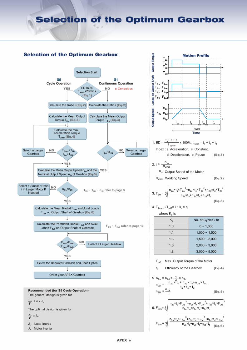
Selection of the Optimum Gearbox
Calculate the Mean Output Torque T 2m (Eq.3)
Select a Larger Gearbox
Select a Smaller Ratioi in Larger Motor If
Needed
Calculate the Mean Output Speed n and the 2m
Nominal Output Speed n of Gearbox 2N (Eq.5)
Calculate the Mean Radial F and Axial Loads2rm
F on Output Shaft of Gearbox 2am (Eq.6)
NOYES
S5Cycle Operation
S1Continuous Operation
Calculate the Ratio i (Eq.2)
Calculate the Mean Output Torque T 2m (Eq.3)
Selection Start
ED<60%t <20minswork
(Eq.1)
Calculate the Ratio i (Eq.2)
T <T2max 2B
T <T 2m 2N
Calculate the max.Acceleration Torque
T2max (Eq.4)
NO
YES
T <T2m 2N
NO Select a Larger Gearbox
YES
n <n2m 2NNO
YES
Calculate the Permitted Radial F and Axial 2rB
Loads F on Output Shaft of Gearbox2aB
YES
F <F2rm 2rB
F <F2am 2aB
NOSelect a Larger Gearbox
Select the Required Backlash and Shaft Option
Order your APEX Gearbox
T 、 T 、 n refer to page 3 2B 2N 1N
F 、 F refer to page 10 2rB 2aB
Recommended (for S5 Cycle Operation)
The general design is given for
The optimal design is given for
J Load InertiaL
J Motor Inertiam
≤ 4 x Jm
JL
2i
Jm
JL
2i
1. ED = x 100%, t work = t + t + ta c d
Index : a. Acceleration, c. Constant,
d. Deceleration, p. Pause (Eq.1)
tat cycle
+ t + tc d
nmnwork
2. i
nm Output Speed of the Motor
nwork Working Speed (Eq.2)
3 3 3n t T +n t T n t T2a a 2c c 2d d× × × × × ×+2a 2c 2d
n t +n t +n t2a a 2c c 2d d× × ×3. T = 32m
(Eq.3)
4. T =T i k η2max mB s × × ×
where K iss
T Max. Output Torque of the MotormB
η Efficiency of the Gearbox
Ks
1.0
1.1
1.3
1.6
1.8
No. of Cycles / hr
0 ~ 1,000
1,000 ~ 1,500
1,500 ~ 2,000
2,000 ~ 3,000
3,000 ~ 5,000
(Eq.4)
5. n = n = n2a 2d 2c×
n = 2m
n = 2N
12
n t + n t +n t2a a 2c c 2d d
t + t + ta c d
× × ×
n1N
i(Eq.5)
6. F = 32rm
F = 32am
3 3n t F n t n t2a a 2c c 2d d× × × × × ×
3+ F + F2ra 2rc 2rd
n t +n t +n t2a a 2c c 2d d× × ×
3 3n t F n t n t2a a 2c c 2d d× × × × × ×
3+ F + F2aa 2ac 2ad
n t +n t +n t2a a 2c c 2d d× × ×(Eq.6)
Motion Profile
Time
tdta
tcycle
tptc
T2a
T2cT2p
T2d
Ou
tpu
t S
peed
Ou
tpu
t To
rqu
eL
oad
s o
n O
utp
ut
Sh
aft
Selection of the Optimum Gearbox
L
X
F 2r
F Radial Load2r
F Axial Load2a
F2a2 F2a1
Consult us

APEX 10
Permitted Radial and Axial Loads on Output Shaft of the Gearbox
Pe
rmit
ted
Ra
dia
l L
oa
d F
[ N
]2
rB
On
Ce
nte
r P
os
itio
n o
f S
ha
ft AB220 / ABR220
AB180 / ABR180
AB115 / ABR115
AB142 / ABR142
AB042 / ABR042
AB060 / AB060A /ABR060
AB090 / AB090A /ABR090
1,000
100,000
60,000
40,000
20,000
10,000
6,000
4,000
2,000
3002000100060040020010060402010
Output Speed n [ rpm ]2
If radial force F exert on the 2r
center of the output shaft
X=1/2 x L.
Under various operating
condition the lifetime is over
20,000 hours.
The permitted radial load is
given on left diagram.
1.5
1.4
1.3
1.2
1.1
1.0
0.9
0.8
0.7
0.6
0.5
0.4
0.3
0 40 80 120 160 200 240 280 320 360 400
AB042 / ABR042
AB060 / AB060A /ABR060AB090 / AB090A /ABR090
AB115 / ABR115
AB142 / ABR142
AB180 / ABR180
AB220 / ABR220
Position X [ mm ]
Po
sit
ion
Lo
ad
Fa
cto
r k
b
If radial force F not exert on2r
the center of the output shaft
X<1/2 x L or X>1/2 x L
The permitted radial and axial
load can be calculated by the
position load factor K on the b
left diagram.
The permitted radial and axial loads on output shaft of the gearbox
depend on the design of the gearbox supporting bearings.
APEX use the extension straddle oversized ball bearing design.
It can take heavy load from both axes.
*
*S1 service life 10,000 hrs
APEX 9
Selection of the Optimum Gearbox
Calculate the Mean Output Torque T 2m (Eq.3)
Select a Larger Gearbox
Select a Smaller Ratioi in Larger Motor If
Needed
Calculate the Mean Output Speed n and the 2m
Nominal Output Speed n of Gearbox 2N (Eq.5)
Calculate the Mean Radial F and Axial Loads2rm
F on Output Shaft of Gearbox 2am (Eq.6)
NOYES
S5Cycle Operation
S1Continuous Operation
Calculate the Ratio i (Eq.2)
Calculate the Mean Output Torque T 2m (Eq.3)
Selection Start
ED<60%t <20minswork
(Eq.1)
Calculate the Ratio i (Eq.2)
T <T2max 2B
T <T 2m 2N
Calculate the max.Acceleration Torque
T2max (Eq.4)
NO
YES
T <T2m 2N
NO Select a Larger Gearbox
YES
n <n2m 2NNO
YES
Calculate the Permitted Radial F and Axial 2rB
Loads F on Output Shaft of Gearbox2aB
YES
F <F2rm 2rB
F <F2am 2aB
NOSelect a Larger Gearbox
Select the Required Backlash and Shaft Option
Order your APEX Gearbox
T 、 T 、 n refer to page 3 2B 2N 1N
F 、 F refer to page 10 2rB 2aB
Recommended (for S5 Cycle Operation)
The general design is given for
The optimal design is given for
J Load InertiaL
J Motor Inertiam
≤ 4 x Jm
JL
2i
Jm
JL
2i
1. ED = x 100%, t work = t + t + ta c d
Index : a. Acceleration, c. Constant,
d. Deceleration, p. Pause (Eq.1)
tat cycle
+ t + tc d
nmnwork
2. i
nm Output Speed of the Motor
nwork Working Speed (Eq.2)
3 3 3n t T +n t T n t T2a a 2c c 2d d× × × × × ×+2a 2c 2d
n t +n t +n t2a a 2c c 2d d× × ×3. T = 32m
(Eq.3)
4. T =T i k η2max mB s × × ×
where K iss
T Max. Output Torque of the MotormB
η Efficiency of the Gearbox
Ks
1.0
1.1
1.3
1.6
1.8
No. of Cycles / hr
0 ~ 1,000
1,000 ~ 1,500
1,500 ~ 2,000
2,000 ~ 3,000
3,000 ~ 5,000
(Eq.4)
5. n = n = n2a 2d 2c×
n = 2m
n = 2N
12
n t + n t +n t2a a 2c c 2d d
t + t + ta c d
× × ×
n1N
i(Eq.5)
6. F = 32rm
F = 32am
3 3n t F n t n t2a a 2c c 2d d× × × × × ×
3+ F + F2ra 2rc 2rd
n t +n t +n t2a a 2c c 2d d× × ×
3 3n t F n t n t2a a 2c c 2d d× × × × × ×
3+ F + F2aa 2ac 2ad
n t +n t +n t2a a 2c c 2d d× × ×(Eq.6)
Motion Profile
Time
tdta
tcycle
tptc
T2a
T2cT2p
T2d
Ou
tpu
t S
peed
Ou
tpu
t To
rqu
eL
oad
s o
n O
utp
ut
Sh
aft
Selection of the Optimum Gearbox
F Radial Load2r
F Axial Load2a
Consult us

APEX DYNAMICS, INC.
HIGH PRECISION PLANETARY GEARBOXES
AB SeriesAB Series
ABR090 010 P1- -
Gearbox Size:
ABR042, ABR060, ABR090
ABR115, ABR142, ABR180,
ABR220
Shaft Option:
S1: Smooth Output Shaft
S2: Output Shaft with Key
Ratio:
1 Stage: 3, 4, 5, 6, 7, 8, 9, 10, 14, 20
2 Stage: 15, 20, 25, 30, 35, 40, 45, 50, 60, 70,
80, 90, 100, 120, 140, 160, 180, 200
Backlash:
P0: Micro Backlash
P1: Reduced Backlash
P2: Standard Backlash
S1- MOTOR/
AB090 010 P1- -
Gearbox Size:
AB042, AB060, AB060A, AB090, AB090A
AB115, AB142, AB180, AB220
S1- MOTOR/
Ordering Example: ABR090-010-S1-P1 / SIEMENS 1FT6 041-4AF71
ABR SeriesABR Series
Please visit our website for newest update data.
Ordering Example: AB090-010-S1-P1 / SIEMENS 1FT6 041-4AF71
Ordering Code
Shaft Option:
S1: Smooth Output Shaft
S2: Output Shaft with Key
Ratio:
1 Stage: 3, 4, 5, 6, 7, 8, 9, 10
2 Stage: 15, 20, 25, 30, 35, 40, 45, 50, 60, 70,
80, 90, 100
Backlash:
P0: Micro Backlash
P1: Reduced Backlash
P2: Standard Backlash
Motor Designation:
Manufacturer Type
And Model
Motor Designation:
Manufacturer Type
And Model
No.10, Keyuan 3rd Rd., Situn District, Taichung City 407, Taiwan (R.O.C.)
Tel: 886 4 23550219 / Fax: 886 4 23550218
E-mail: [email protected]
Website: www.apexdyna.com
APEX DYNAMICS, INC.
APEX-2011-12-AB / ABA / ABR-2.0E-3.3V


