188
Motor Handbook Sixth Edition, April 2006 Version 1.3

Motor Handbook
Sixth Edition, April 2006 Version 1.3

This Handbook Is Intended To Be An Aid To The Operator And Is Solely Provided For Information And Illustration
Purposes.
Please Feel Free To Contact Any Of Our Locations With Questions Not Answered In This Handbook.
The Technical Data And Text In This Handbook Is Subject To Change Without Notice.
Sixth Edition (2006) [Version 1.3]
Made in Canada
ISO 9001: 2000
Licensed Manufacturer Under: 09696:801197 API Spec. 7 - License Number 7-0063 09696:802078 Website: www.nov.com Email: [email protected]

- I -
Contents
1. General ................................................................ 1-1 Preface .......................................................................1-1 Background ................................................................1-1 Economics ..................................................................1-2 Glossary of Terms ......................................................1-2
2. Motor Selection .................................................... 2-1 Versatility ....................................................................2-1
3. Motor Components............................................... 3-1 Dump Sub...................................................................3-2 Power Section ............................................................3-2 Adjustable Housing.....................................................3-3 Fixed Housing.............................................................3-3 Articulated Driveshaft .................................................3-4 Sealed Bearing Assembly ..........................................3-4 Stabilizers ...................................................................3-5
4. Servicing .............................................................. 4-1
5. Operation ............................................................. 5-1 Preparation for Running and Rig Site Motor Test.......5-1 Running In ..................................................................5-2 Starting the Motor .......................................................5-2 Drilling.........................................................................5-2 Reactive Torque .........................................................5-3 Stalling ........................................................................5-4 Over-running the Bit ...................................................5-4 Rotary RPM ................................................................5-5 Motor Pressure Drop ..................................................5-5 Bit Pressure Drop .......................................................5-5 Drilling Fluids ..............................................................5-6 Oil Based Drilling Fluids ......................................5-6 H2S (Sour) Service.............................................5-7 Down-hole Temperature.............................................5-8 Plugging Off ................................................................5-8 Hydraulic Extension....................................................5-9 Partial Rotor Bypass...................................................5-9 Tripping Out of the Hole and Checking the Tool ......5-10 Rig Site Maintenance................................................5-10
6. Applications.......................................................... 6-1 Deflection Devices......................................................6-1 Steerable Systems .....................................................6-1 Performance Drilling ...................................................6-2

- II -
Re-Entry Medium Radius Drilling/Horizontal Drilling Systems...............................................................6-2 Short Radius Drilling Systems ....................................6-3 Milling..........................................................................6-3 Coring .........................................................................6-4 Ratholes, Mouseholes and Spudding.........................6-4 Workover ....................................................................6-4
7. Air or Two-Phase Drilling ..................................... 7-1 Selection / Startup ......................................................7-1 Fluid / Lubricant Requirements...................................7-2 Pressures ...................................................................7-3 Temperature ...............................................................7-3 Volume Requirements ................................................7-3 Operation....................................................................7-3 Drilling with Nitrogen (N2) ...........................................7-4
8. Fishing Information/Safety Features .................... 8-1
9. Trouble Shooting.................................................. 9-1 Sudden Pressure Increase .........................................9-1 No Penetration............................................................9-1 Slow Pressure Decrease ............................................9-1
10. Motor Performance Summary ............................ 10-1 Availability of Power Sections ..................................10-7
11. Motor Performance Data.................................... 11-1
1 7/16” 1/2 High Speed 3.0 Stage 11-4 1 11/16” 5/6 Multi-Lobe 2.5 Stage 11-6 1 11/16” 5/6 Multi-Lobe 4.4 Stage 11-8 1 11/16” 5/6 Multi-Lobe 5.0 Stage 11-10 2 1/8” 5/6 Multi-Lobe 3.0 Stage 11-12 2 1/8” 5/6 Multi-Lobe 6.0 Stage 11-14 2 3/8” 1/2 High Speed 7.0 Stage 11-16 2 3/8” 2/3 Multi-Lobe 4.0 Stage 11-18 2 3/8” 4/5 Multi-Lobe 3.0 Stage 11-20 2 3/8” 5/6 Multi-Lobe 2.5 Stage 11-22 2 3/8” 5/6 Multi-Lobe 5.2 Stage 11-24 2 3/8” 7/8 Multi-Lobe 4.0 Stage 11-26 2 7/8” 1/2 High Speed 5.2 Stage 11-28 2 7/8” 1/2 High Speed 7.0 Stage 11-30 2 7/8” 3/4 Multi Lobe 4.0 Stage 11-32 2 7/8” 4/5 Multi-Lobe 3.0 Stage 11-34 2 7/8” 5/6 Multi Lobe 3.3 Stage 11-36 2 7/8” 5/6 Multi-Lobe 4.7 Stage 11-38 2 7/8” 5/6 Multi-Lobe 4.7 Stage - 4° 11-40 2 7/8” 5/6 Multi-Lobe 7.0 Stage 11-42

- III -
2 7/8” 5/6 Multi-Lobe 7.0 Stage - 4° 11-44 2 7/8” 7/8 Multi-Lobe 1.5 Stage 11-46 2 7/8” 7/8 Multi-Lobe 1.5 Stage - 4° 11-48 2 7/8" 7/8 Multi-Lobe 2.0 Stage (Air) 11-50 2 7/8" 7/8 Multi-Lobe 2.0 Stage - 4° 11-52 2 7/8” 7/8 Multi-Lobe 2.5 Stage 11-54 2 7/8" 7/8 Multi-Lobe 2.5 Stage - 4° 11-56 3 1/8” 5/6 Multi-Lobe 3.5 Stage 11-58 3 1/8” 7/8 Multi-Lobe 3.0 Stage 11-60 3 1/8” 7/8 Multi-Lobe 4.0 Stage 11-62 3 3/8” 1/2 High Speed 5.5 Stage 11-64 3 3/8” 4/5 Multi-Lobe 5.0 Stage 11-66 3 3/8” 7/8 Multi-Lobe 3.0 Stage 11-68 3 1/2” 4/5 Multi-Lobe 4.0 Stage 11-70 3 1/2” 5/6 Multi-Lobe 2.0 Stage 11-72 3 1/2” 5/6 Multi-Lobe 2.0 Stage - 4° 11-74 3 1/2” 5/6 Multi-Lobe 3.0 Stage 11-76 3 1/2” 7/8 Multi-Lobe 3.8 Stage 11-78 3 1/2” 7/8 Multi-Lobe 4.3 Stage 11-80 3 3/4” 1/2 High Speed 4.4 Stage 11-82 3 3/4" 3/4 Multi-Lobe 9.0 Stage 11-84 3 3/4” 4/5 Multi-Lobe 3.5 Stage 11-86 3 3/4” 5/6 Multi-Lobe 5.0 Stage (OS) 11-88 3 3/4” 6/7 Multi-Lobe 3.0 Stage 11-90 3 3/4” 7/8 Multi-Lobe 2.0 Stage 11-92 3 3/4” 7/8 Multi-Lobe 2.3 Stage 11-94 3 3/4” 7/8 Multi-Lobe 2.3 Stage - 4° 11-96 3 3/4” 7/8 Multi-Lobe 6.7 Stage 11-98 3 3/4" 7/8 Multi-Lobe 10.1 Stage 11-100 4 3/4” 1/2 High Speed 3.0 Stage 11-102 4 3/4" 1/2 High Speed 4.0 Stage 11-104 4 3/4” 1/2 High Speed 6.5 Stage 11-106 4 3/4" 2/3 Multi-Lobe 8.0 Stage 11-108 4 3/4" 3/4 Multi-Lobe 9.9 Stage 11-110 4 3/4” 4/5 Multi-Lobe 3.5 Stage 11-112 4 3/4” 4/5 Multi-Lobe 6.0 Stage 11-114 4 3/4” 4/5 Multi-Lobe 6.3 Stage 11-116 4 3/4” 5/6 Multi-Lobe 3.0 Stage 11-118 4 3/4” 5/6 Multi-Lobe 3.0 Stage - 4° 11-120 4 3/4" 5/6 Multi-Lobe 8.3 Stage 11-122 4 3/4" 6/7 Multi-Lobe 6.0 Stage 11-124 4 3/4” 7/8 Multi-Lobe 2.0 Stage (Air) 11-126 4 3/4” 7/8 Multi-Lobe 2.0 Stage - 4° 11-128 4 3/4” 7/8 Multi-Lobe 2.2 Stage 11-130 4 3/4” 7/8 Multi-Lobe 2.2 Stage - 4° 11-132

- IV -
4/3/4” 7/8 Multi-Lobe 3.8 Stage 11-134 5” 6/7 Multi-Lobe 6.0 Stage 11-136 5” 6/7 Multi-Lobe 7.0 Stage 11-138 5” 6/7 Multi-Lobe 8.0 Stage 11-140 6 1/4” 1/2 High Speed 4.0 Stage 11-142 6 1/4” 4/5 Multi-Lobe 4.3 Stage 11-144 6 1/4” 4/5 Multi-Lobe 7.5 Stage 11-146 6 1/4” 5/6 Multi-Lobe 5.0 Stage 11-148 6 1/4” 5/6 Multi-Lobe 5.5 Stage 11-150 6 1/4” 7/8 Multi-Lobe 2.8 Stage 11-152 6 1/4” 7/8 Multi-Lobe 2.9 Stage 11-154 6 1/4” 7/8 Multi-Lobe 3.0 Stage 11-156 6 1/4” 7/8 Multi-Lobe 4.8 Stage 11-158 6 3/4" 1/2 High Speed 3.0 Stage 11-160 6 3/4” 1/2 High Speed 4.0 Stage 11-162 6 3/4” 2/3 Multi-Lobe 7.0 Stage (OS) 11-164 6 3/4” 4/5 Multi-Lobe 4.8 Stage 11-166 6 3/4” 4/5 Multi-Lobe 7.0 Stage 11-168 6 3/4” 5/6 Multi-Lobe 5.0 Stage 11-170 6 3/4” 6/7 Multi-Lobe 5.0 Stage 11-172 6 3/4” 6/7 Multi-Lobe 6.0 Stage 11-174 6 3/4” 7/8 Multi-Lobe 2.0 Stage (Air) 11-176 6 3/4” 7/8 Multi-Lobe 2.9 Stage 11-178 6 3/4” 7/8 Multi-Lobe 3.0 Stage 11-180 6 3/4” 7/8 Multi-Lobe 3.5 Stage 11-182 6 3/4” 7/8 Multi-Lobe 5.0 Stage 11-184 6 3/4” 7/8 Multi-Lobe 5.7 Stage 11-186 6 3/4” 7/8 Multi-Lobe 6.4 Stage 11-188 7” 7/8 Multi-Lobe 6.0 Stage 11-190 7” 7/8 Multi-Lobe 7.5 Stage 11-192 7 3/4” (8") 1/2 High Speed 4.0 Stage 11-194 7 3/4” (8") 4/5 Multi-Lobe 3.6 Stage 11-196 7 3/4” (8") 4/5 Multi-Lobe 5.3 Stage 11-198 7 3/4” (8") 5/6 Multi-Lobe 5.0 Stage 11-200 7 3/4” (8") 6/7 Multi-Lobe 4.0 Stage 11-202 7 3/4" (8") 7/8 Multi-Lobe 2.0 Stage (Air) 11-204 7 3/4" (8") 7/8 Multi-Lobe 3.0 Stage 11-206 7 3/4" (8") 7/8 Multi-Lobe 4.0 Stage 11-208 8" 6/7 Multi-Lobe 5.0 Stage 11-210 9 5/8” 1/2 High Speed 4.0 Stage 11-212 9 5/8” 2/3 Multi-Lobe 7.5 Stage 11-214 9 5/8” 3/4 Multi-Lobe 4.5 Stage 11-216 9 5/8” 3/4 Multi-Lobe 6.0 Stage 11-218 9 5/8” 5/6 Multi-Lobe 3.0 Stage 11-220 9 5/8” 5/6 Multi-Lobe 4.0 Stage 11-222

- V -
9 5/8" 6/7 Multi-Lobe 5.0 Stage
11-224 9 5/8" 6/7 Multi-Lobe 6.0 Stage 11-226 9 5/8" 7/8 Multi-Lobe 5.7 Stage 11-228 11 1/4” 3/4 Multi Lobe 3.6 Stage 11-230 11 1/4” 5/6 Multi Lobe 4.6 Stage 11-232 11 1/4” 6/7 Multi Lobe 3.0 Stage 11-234
12. Adjustable Housing Operating Instructions ........ 12-1
13. Nozzle Selection and Replacement ................... 13-1
14. Engineering Data ............................................... 14-1 Formulas...................................................................14-1 Imperial Conversions................................................14-2 Metric Conversions...................................................14-4 Millimeter Equivalents of Common Inch Measurements...................................................14-6 Millimeter and Decimal Equivalents..........................14-7 Buoyancy Factor for Steel Drill Collars.....................14-8 Collar Weights in Pounds per Foot...........................14-9 Drill Collar Connection Make-up Torque ................14-10 Properties of Drill Pipes and Tool Joints.................14-20 Mechanical Properties of Drill Pipe.........................14-28 Heavy Walled Drill Pipe ..........................................14-32 Drill Bit Sizes ..........................................................14-33 Hole Curvature .......................................................14-34
15. Drilling Tool Data................................................ 15-1 Hydraulic Mechanical Drilling Jars............................15-1 Double Acting Hydraulic Mechanical Drilling Jars ....15-3 Power Stroke Hydraulic Jars ....................................15-5 Shock Tools..............................................................15-6

1-1
GENERAL
Preface Positive Displacement Motors (PDMs) have gained a wide
acceptance in the industry. The Vector™ motor contains many unique features. For example, the Vector™ motor utilizes a rig floor adjustable bent housing between the motor section and the sealed bearing assembly. No drilling fluid passes through the bearings. The sealed bearing assembly contains anti-friction bearings sealed in oil. The rugged articulated driveshaft is sealed and lubricated for long service.
Background National Oilwell Varco, an integrated drilling solutions
company, is a worldwide leader in the design, manufacture and sale of machinery, equipment, and downhole tools, used in the oil and gas drilling and production industries.
National Oilwell Varco designs, manufactures and markets a broad range of downhole products within the Downhole Tools operations. These include highly engineered drilling mud motors for straight hole, directional, short radius and horizontal drilling, in addition to coring, coiled tubing, steerable, workover and intervention applications.
National Oilwell Varco combined the operations of Griffith® Oil Tool and Vector™ Oil Tool. These companies combined in 1996 to create an organization with fully integrated engineering, manufacturing and rental services as well as a worldwide network of sales and service locations. National Oilwell Varco Downhole Tools makes its technologies available through rent, lease, or sale. The company offers innovative asset management programs designed to manage fleet costs and performance.
Griffith® Oil Tool was founded in 1974 to develop products for the drilling industry. These products now include: Hydraulic Mechanical (Double and Single Acting) Drilling Jars, Mechanical And Combination Drilling Jars, Shock Subs, Fishing and Coring Jars, Bumper Subs, Jar Intensifiers, Stabilizers, Reamers, Kelly Valves, Inside Blow Out Preventors, Drop In Check and Wireline Retrievable Safety Valves, Torquemaster Breakout Units, and Service Centers. In 1985 Griffith® Oil Tool began its development and design of downhole motors and related accessories marketed under the Trudril trade name.
Vector™ Oil Tool was founded in 1990 to design and manufacture drilling motors and related components.
National Oilwell Varco Downhole Tools manufactures the components used in downhole products according to strict quality

1-2
assurance and control procedures. National Oilwell Varco Downhole Tools is an ISO 9001 Registered Firm, and is licensed to monogram API Products under Spec 7 License No. 7-0063.
Economics The increasing reliability of drilling motors in combination with
improved drill bit designs and measurement while drilling (MWD) systems now present operators with alternatives to rotary drilling in an increasing number of applications.
It is generally acknowledged that an effective downhole motor, matched to the drill bit and formation, provides better rates of penetration than rotary drilling.
In addition to increasing rate of penetration, a mud motor allows a reduction in drillstring rotary RPM that reduces wear on the casing and wear and fatigue of the drillstring and rotating topside components. It also provides more effective control over deviation and doglegs.
Drilling with a motor can be more fuel efficient because the hydraulic power required driving the downhole motor and drill bit may be less than the mechanical power required driving a rotating drill string with the associated friction losses.
Glossary of Terms Various manufacturers and users use different names for the
same piece of equipment. This can make it confusing in reviewing literature discussing the same topics. The following are the component names used at National Oilwell Varco Downhole Tools.
Bent Sub is used on the top of a drilling motor assembly to cause deflection.
Orientable Bent Sub is a bent sub that can be aligned with the bend in the bent housing.
Dump Sub (by-pass valve, dump valve or by-pass sub) is used above the motor section of a positive displacement motor to allow the drill string to fill when tripping into the hole, and drain when tripping out of the hole.
Top Sub

1-3
is a crossover, used instead of a dump sub, that couples the motor section to the drillstring.
Power Section (motor section, motor assembly, multistage motor, positive displacement motor (PDM) drive, or rotor and stator) is the drive section of the downhole motor that converts hydraulic energy into mechanical energy to drive the drill bit.
Bent Housing (bent coupling housing) is a housing enclosing the articulated driveshaft connected to the stator above and the sealed bearing assembly below. It creates an angle between the axis of the drilling motor components above it and the drilling motor components below it. This angle is what causes the deflection, or build angle, of the well path. This housing is most often adjustable.
Articulated Driveshaft (connecting rod assembly, flex coupling, universal joint, or coupling assembly) is a shaft with universal joints that transmits power from the motor section above it to the sealed bearing assembly below it.
Sealed Bearing Assembly (output shaft assembly, bearing pack, or bearing assembly) is the assembly between the bent housing and the bit, which contains the axial and radial bearings and the output shaft. National Oilwell Varco Downhole Tools refers to its bearing assembly as a Sealed Bearing Assembly because the bearings are sealed in a pressure balanced oil filled chamber, rather than exposed to drilling mud. Vector™ series 24 and 24X sealed bearing assemblies utilize a flow restrictor to balance the oil chamber to bit pressure drop. This flow restrictor is located at the rotating output shaft. It is normal to see 3-5% of the total fluid flow exiting the motor at the ouput shaft. This fluid should not be mistaken as a damaged seal in the motor.
Bearing Mandrel (Output shaft or drive shaft) is the rotating shaft at the bottom of the bearing assembly that drives the bit.
2-1
MOTOR SELECTION Vector™ motors are generally supplied in the configuration shown below. Alternates and options are shown, as applicable:
♦ Dump Sub
Alternate Top Sub or Plugged Dump Sub
Alternate Bent Sub
Alternate Float Sub
♦ Power Section (High, Medium Or Low Speed)
Alternate Oversized Stator
Optional Jetted Rotor
♦ Bent Housing
Alternate Straight Housing
Alternate Fixed Bent Housing
Alternate Adjustable Bent Housing, 4° max.
♦ Articulated Driveshaft
Alternate Flex Shaft
♦ Sealed Bearing Assembly w/Thread Protector for
slick assembly
Alternate Screw-on Stabilizer.
Optional components:
♦ Universal Bottom Hole Orientation Sub (UBHO)
Versatility The Vector™ low speed, high torque, multi-lobe (M/L) and
high speed (H/S) motors offer the operator unprecedented flexibility in the field.
Extended time between service intervals result from the use of a sealed bearing assembly and articulated driveshaft with sealed universal joints. This, plus the ability to set the adjustable bent housing angle, and install or remove screw-on stabilizers onto the sealed bearing assembly on the rig floor, provide a single motor design suitable for a full range of applications.
The M/L series motors – 2 7/8” and larger, can be supplied with a field replaceable rotor bypass for high circulating rates.
Refer to Section 13 for Nozzle Selection and Replacement.

3-1
MOTOR COMPONENTS

3-2
Dump Sub
The dump sub allows fluid to bypass the motor section and fill the bore of the drill string when tripping into the hole. It also allows the bore of the drill string to drain when tripping out of the hole. When no dump sub is used, a wet trip out of the hole will occur.
At low circulation rates, a spring holds a ported piston in the upper position, exposing ports in the dump sub body which allow drilling fluid to flow into or out of the drill string while tripping. When the rig pumps are started, the flow through the piston bore causes a pressure drop across the ports in the piston. This forces the piston down, overcoming the spring force and closing the ports which in turn directs the drilling fluid through the motor. When the rig pumps are stopped, the spring forces the piston up, opening the ports.
Vector™ dump subs are preset to close at less than the minimum recommended circulation rate of the motor assembly. There is little pressure loss through the dump sub when operating.
The top connection of a Vector™ dump sub is an API tool joint box. The lower connection is a Vector™ designed thread form that connects to the box of the stator housing.
Power SectionThe drive is a Moineau1 pump operated in reverse. Drilling
fluid pumped through the assembly causes a rotor to turn and apply rotary motion and torque to the drill bit, through the articulated driveshaft and the output shaft in the sealed bearing assembly.
The power section consists of a helical shaped rotor running inside the stator (an elastomer liner bonded to a steel tube). The stator elastomer liner opening is dissimilar in shape to the rotor. The pitch length of the stator cavity is longer than the pitch length of the rotor. The dissimilarity in the shapes of the rotor and stator produces wedge shaped cavities that are sealed along their edges. The pressure that is produced as drilling fluid is pumped through the motor section causes the rotor to turn and the cavities to move forward in the direction of fluid flow.
The 1 to 2 lobe configuration, used in Vector™ high-speed motors, has a helical shaped rotor with a circular cross section (1 lobe). The elastomer liner opening of the stator is oblong in cross section (2 lobes), and is molded in a helical shape with a pitch length twice that of the rotor pitch length.
1 “Moineau” - Reference Is Made To The Inventor Of The Progressing Cavity Pump.

3-3
The multi-lobe configuration, employed in Vector™ low speed, high torque motors, uses a rotor with a multiple-lobed cross section that also forms a helix. The elastomer liner in the stator has a cross section containing one more lobe than the rotor. Its pitch length is longer than the rotor’s pitch length by the ratio of the number of stator lobes divided by the number of rotor lobes. Example: A 7 to 8 lobe configuration has 7 lobes on the rotor, 8 lobes in the stator; and a helical pitch length of the stator equal to 8 / 7 times the pitch length of the rotor.
The number of stages of a Vector™ PDM drive is the length of the stator elastomer liner divided by its pitch length.
Vector™ PDM drives permit accurate determination of the bit speed and bit torque “on bottom” from the rig floor at any time by referring to the accompanying Motor Specifications and Performance pages. The output torque is directly proportional to the pressure drop across it. This is a straight-line relationship and can be determined from the standpipe pressure gauge. The PDM drive’s speed is proportional to the circulation rate.
At a constant circulation rate, the speed drops off slightly as the torque and pressure increase. This is reflected in the motor performance charts shown in Section 11. The circulation rate can be read from the pump stroke counter.
The stator is threaded on both ends with a box that uses a Vector™ designed thread. It connects to the dump sub above and to the bent housing below.
The rotor has a box connection that connects to the upper universal joint of the articulated driveshaft assembly.
Adjustable Housing The Vector™ adjustable housing connects the stator to the
sealed bearing assembly and encloses the articulated driveshaft assembly. The angle setting is field adjustable to produce a wide range of build rates.
Operation of the 0 - 3° (degree), or 0 - 4° adjustable housing, is outlined in Section 12.
Fixed Housing Fixed, non-adjustable housings are available (special order)
in straight or fixed bend configurations.

3-4
Articulated Driveshaft The articulated driveshaft assembly converts the eccentric or
processional motion of the rotor into concentric rotation for input to the sealed bearing assembly. It also accommodates any angle set on the adjustable bent housing (or fixed bend housing) and carries the thrust load from the rotor caused by the pressure drop across it.
The assembly consists of two universal joints connected by a driveshaft. The upper joint connects to the rotor and the lower joint connects to the sealed bearing assembly. Both universal joints are lubricated, sealed, and pressure balanced.
Sealed Bearing Assembly The sealed bearing assembly transmits the rotation of the
rotor, through the articulated driveshaft assembly, to the drill bit. It carries the compressive thrust load created by the weight on bit, and the radial and bending loads developed while directional or steerable drilling. It also carries the tensile “off-bottom” thrust load produced by the pressure drops across the rotor and the drill bit, as well as any load caused by back reaming.
The Vector™ radial bearings and thrust bearings are sealed in an oil chamber balanced to the hydrostatic pressure. The thrust bearings are high capacity and there is no need to balance hydraulic thrust load to bit load with the Vector™ motor. The high capacity radial bearings readily withstand side loads caused by drilling with a deflection device or uneven cutting action along the drill bit periphery.
The lower connection is an API regular bit box.

3-5
Stabilizers Vector™ motors are available with a thread on the outside of
the sealed bearing assembly to accept straight or spiral blade screw-on stabilizers or screw-on offset pads. A protector is installed over this thread when stabilizers or offset pads are not being used.
Specify stabilizer / pad OD when ordering.
Stabilizers, thread protectors and offset pads should be torqued to the values shown below.
Make-up Torque,
Stabilizers, Thread Protectors and Offset Pads
Tool Size lb-ft N.m
1 7/16” N/A N/A 1 11/16” N/A N/A 2 1/8” N/A N/A 2 3/8” N/A N/A 2 7/8” 2,000 2 700 3 1/8” N/A N/A 3 3/8” N/A N/A 3 1/2” 2,000 2 700 3 3/4” 4,200 5 700
4 3/4” / 5” 6,000 8 100 6 1/4” 10,000 13 550
6 3/4” / 7” 12,000 16 250 7 3/4” / 8” 20,000 27 000
9 5/8” 25,000 33 900 11 1/4” 32,000 43 000

4-1
SERVICING National Oilwell Varco Downhole Tools recommends that its
downhole motors be serviced after every run and be returned to an authorized National Oilwell Varco Downhole Tools service center.
At a National Oilwell Varco Downhole Tools authorized service center, the motors are visually inspected, flushed and, if necessary, run in the test stand before disassembly. Motors are completely disassembled and all parts cleaned and inspected. Threaded connections and critical components in the motors are magnetic particle inspected by operators qualified in accordance with SNT-TC-1A. Threads and parts are redressed as necessary and worn parts are replaced. Make-up and breakout of all threaded connections is performed with an accurate torque machine (e.g. Griffith® Torquemaster or Mini-Torque) to ensure proper torque is applied to the threaded connection. Following re-assembly the tool is filled with oil and tested for proper operation.
It may become necessary to remove and replace the dump sub or top sub in the field (e.g. to replace a rotor jet, if so equipped). If so, the connection should be torqued to the values specified below:
Make-up Torque, Dump Sub (or Top Sub) to Stator
Tool Size lb-ft N.m
1 7/16” 300 400 1 11/16” 750 1 000 2 1/8” 1,250 1 700 2 3/8” 1,600 2 200 2 7/8” 2,400 3 250 3 1/8” 3,800 5 100 3 3/8” 4,500 6 100 3 1/2” 5,000 6 800 3 3/4” 5,300 7 200 4 3/4” 10,000 14 000
5” 15,000 20 300 6 1/4” 25,000 33 900
6 3/4” / 7” 28,000 38 000 7 3/4” / 8” 42,000 56 900
9 5/8” 68,000 92 000 11 1/4” 80,000 108 000

5-1
OPERATION No matter whether the application is a correction run,
directional kick-off, sidetrack extended reach, horizontal well, or a coring run, careful consideration of all parameters will go a long way in ensuring the successful execution of the planned task.
Hydraulic requirements, circulating fluid data, R.P.M. requirements, and formation characteristics must be addressed to ensure the proper selection of the applicable Vector™ motor.
Preparation for Running and Rig Site Motor Test Vector™ downhole motors are shipped from the service
center with all tool connections made up to the proper torque, and all components inspected and tested for satisfactory operation. High torque low speed motors are shipped with the rotor bore plugged unless otherwise specified. All motors are shipped with a protector covering the screw-on stabilizer thread unless a screw-on stabilizer is ordered. When ordered in advance, the screw-on stabilizer is installed at the service center before shipment.
Although Vector™ motors are tested prior to shipment, we recommend the following check:
Set the motor in the slips and install a safety clamp. Remove the lift sub and make up the kelly. Remove the safety clamp and slips and lower the motor until the dump sub is below the drilling nipple, but visible. Start the rig pumps slowly; Fluid should flow out of the dump sub ports.
Increase the pump rate slowly until the dump sub closes. Leave the pumps running and make note of the circulation rate and stand pipe pressure when the dump sub closes. With the pump running and the dump sub closed, check to ensure that there is no drill fluid leakage through the ports. It is advisable to increase the pump speed in two or three steps, to the maximum circulation rate expected downhole, and note the circulation rate and standpipe pressure in each case. Shut down the pump. The dump sub may not open due to a pressure lock in the short hydraulic test circuit. If this occurs, bleed off the pressure to permit the dump sub to open.
Make up the drill bit to the proper torque with a bit breaker and the rig tong placed on the output shaft directly above the bit. Do not put rig tongs on the sealed bearing assembly housings. Inspect the output shaft seal area for any indication of an oil leak.

5-2
Vector™ motors are shipped from the service center with the adjustable housing set at zero degrees. To set the adjustable housing to a different angle, Refer to Section 12 for “Adjustable Housing Operating Instructions”.
Running In The drill string with a straight Vector™ motor installed can be
run into the hole normally. When using a bent sub, or a non-zero angle in the adjustable housing, be careful passing the motor through the blowout preventors, casing shoes, liner hangers, ledges, or key seats to ensure that the motor or drill bit does not hang up. Do not run into bottom, or “bottom fill”, as it could plug the bit or damage the motor.
Starting the Motor Begin circulating “off bottom” with the bit turning freely.
Perform circulation and pressure tests at the same circulation rates as the prior surface test, and note the readings. The pressure will be higher due to the restrictions of the drill string components added. The “off bottom” pressures noted may be higher than calculated. This is caused by bit drag on the side of the hole due to the bent sub, adjustable housing angle and stabilization.
DrillingAfter a short hole-cleaning circulation period, slowly lower the
bit to bottom. When bottom is tagged, the standpipe pressure gauge will show an immediate increase. Increase the bit weight slowly to achieve the desired build up rate and/or rate of penetration. Do not exceed the recommended maximum differential pressure across the motor.
The “off bottom” pressure is the total system pressure (read on the stand pipe gauge), from the standpipe, through the drillstring, the annulus, and back to the drilling nipple, while circulating with the bit “off bottom” (i.e. zero weight on bit).
Periodically recheck the “off bottom” pressure. The standpipe pressure will slowly increase after hole cleaning due to the hydraulic energy required to lift the cuttings.
The torque applied to the bit while “on bottom” is directly proportional to the difference between the “on bottom” and “off bottom” pressures (i.e. there are no friction losses through the rotating drill string). An increase in the weight on bit produces an increase in torque. As the bit drills off, the weight on bit decreases and correspondingly the pressure and torque decrease. The standpipe pressure gauge can therefore be used as a torque indicator.

5-3
The range of Vector™ motors permits selection of the correct motor to provide the optimum combination of bit speed, bit torque, and circulation rate for maximum rates of penetration. When the drilling conditions permit, the rotary can be engaged.
Running into bottom can damage thrust bearings, and excessive overpull on a stuck bit can damage “off bottom” bearings in the sealed bearing assembly.
Vector™ motors are designed for extended intervals of “on bottom” drilling. The motors should be serviced after a maximum of 150 operating hours, under ideal drilling conditions. Drilling conditions other than ideal, such as excessive bit weight, corrosive drilling fluids or rotating with high bend settings will reduce this interval accordingly.
Reactive Torque The drill bit attached to the mud motor at the bit box turns in a
right hand, or clockwise direction, if viewed from the drill floor. There is a reactive, counter clockwise (or left-hand) torque produced as a result of the torque applied to the bit. This anti-clockwise torque must be considered when establishing tool face orientation and can be calculated by relating the:
1) difference between “off bottom” free spinning pressure; and
2) actual “on bottom” operating pressure.
A rough, determination of the angle of twist of the drill string can be performed as follows:
1) Measure and record standpipe pressure “on bottom” with the desired bit weight and circulation rate, and “off bottom” with the same circulation rate.
2) From the Motor Specifications and Performance Sheets ( see Section 11) obtain the torque corresponding to the difference between the “on bottom” and “off bottom” pressures.
3) The torsional angle can be determined by multiplying the above torque, the length of drill pipe in the hole, and the angle factors from the table below.
• 3 1/2” - 13.3 lb./ft. Drill Pipe
• Imperial: 8 1/2° (degrees) / 100 lb-ft Torque / 1000 ft.
• Metric: 19° (degrees) / 100 N.m Torque / 1000 m.

5-4
• 3 1/2” - 15.5 lb./ft. Drill Pipe
• Imperial: 7 1/2° (degrees) / 100 lb-ft Torque / 1000 ft.
• Metric: 17° (degrees) / 100 N.m Torque / 1000 m.
• 4 1/2” - 16.6 lb./ft. Drill Pipe
• Imperial: 3 1/3° (degrees) / 100 lb-ft Torque / 1000 ft
• Metric: 7 1/2° (degrees) / 100 N.m. Torque / 1000 m.
• 5” - 19.5 lb./ft. Drill Pipe
• Imperial: 2 5/8° (degrees) / 100 lb-ft Torque / 1000 ft.
• Metric: 6° (degrees) / 100 N.m Torque / 1000 m.
Directional drillers can get an indication of the reactive torque by the measurement while drilling (MWD) equipment, and can adjust and lock the rotary table in order to accommodate the desired tool face direction.
In most applications the use of measurement while drilling or steering tools to provide real time surface readout of azimuth, inclination and tool face is much more reliable than the single shot method of orienting.
Stalling If the drill bit is overloaded, the motor will stall. An increase
in standpipe pressure will occur and penetration will cease.
When a stall occurs, the drilling fluid deforms the stator elastomer liner and flows through the PDM drive without turning the rotor. Bit stall should be avoided, but when it occurs, it should be quickly remedied. Excessive circulation through a stalled PDM drive or repeated stalling will seriously damage the stator elastomer liner and other components within the motor.
If the bit is picked up off-bottom when in a drilling mode, the “trapped” torque within the drill string will be released uncontrollably, potentially causing damage to down-hole components or causing connections to back-off. This is especially true when a stall has occurred.
If a stall condition occurs the following procedure should be followed as soon as possible:
1) Shut down the rotary table immediately.
2) Release trapped torque slowly using the rotary table brake.
3) Lift the bit off bottom, and
4) Shut the pumps off, if necessary.

5-5
Over-running the Bit Rotating the drillstring with any positive displacement motor
in a stalled condition may cause the upper portion of the motor (and drill string) to over-run the bit. This condition may damage the stator elastomer liner. High torque, low speed multi-lobe motors are most susceptible to this type of damage.
Rotary RPM Rotating the drill string while subjected to bending loads
produces fatigue loading on the motor. These bending loads can be produced even when using adjustable bend settings that are within the recommended values (see “Maximum Adjustable Bend Setting for Rotary Drilling” in Section 11). Drill string rotary speed should therefore be limited to 50 RPM to reduce the cyclic loading on the motor.
Motor Pressure Drop Exceeding the recommended operating maximum differential
pressure across the motor will reduce the stator life. Circulation rates exceeding the recommended values also reduce the rotor and stator life.
To understand the conditions affecting the pressure drop across positive displacement drilling motors, the following should be recognized:
The pressure drops across the dump sub, bent housing, articulated driveshaft, and bearing mandrel of the sealed bearing assembly is dependent on the circulation rate only (i.e. torque has no effect). This pressure drop increases as the circulation rate increases.
The pressure drop across the rotor and stator increases linearly as the torque increases, assuming a constant circulation rate.
The effect of mud weight alters the pressure drop across the motor at no load. However, it has a negligible effect on the pressure increase due to the torque “on bottom”.
Bit Pressure Drop Continuous excessive pressure drops across the bit can
cause early seal failure in the sealed bearing assembly. The bit pressure drop should be limited to 1,500 psi (10,000 kPa) for continuous drilling. However, Vector™ motors can be configured to operate with bit pressure drops in excess of 1,500 psi. Please

5-6
contact National Oilwell Varco Downhole Tools engineering if these higher pressures are required.
Drilling Fluids Drilling fluids with a pH below 4 or above 10 can cause
damage to the stator. Circulation through the rotor and stator can minimize this damage and should therefore be maintained when operating in drilling fluids close to the limits of this pH range. Allowing the drilling fluid to stagnate will aggravate the problem.
Pumping acid through a motor can seriously attack the plated components. The motor should be flushed and serviced as soon as possible - refer to “Rig Site Maintenance”.
Drilling fluids containing chlorides can reduce rotor and stator life due to corrosion, especially at elevated temperatures. Special attention should be paid to the internal coatings when the chloride concentration is in excess of 30,000 PPM. Contact National Oilwell Varco Downhole Tools if chloride concentrations are in excess of this. The motor should be flushed and serviced as soon as possible if it has been exposed to chlorides - refer to “Rig Site Maintenance”.
Drilling mud with a density of more than 16.7 PPG (2.00 kgf/l) will cause abnormal erosion of motor internals due to suspended materials within these muds.
Well-mixed medium to fine lost circulation material can be used without plugging or motor damage. If coarse lost circulation material is to be used, a circulating sub should be installed above the motor assembly to bypass the motor.
A Good Rule Of Thumb Is: No More Than 2 1/2 lbs. (1.13 kg) per Barrel.
Sand content should be less than 2%. Solid content of more than 5% will shorten rotor and stator life considerably.
Safe run times may have to be shortened to avoid down-hole motor failure if the above recommendations are not followed.
Never try to cement through a motor as the motor and bit-jets shear the cement and the cement will immediately flash set.
Oil Based Drilling Fluids Vector™ motors can be successfully used in oil based mud if
the operating temperature is below the aniline point of the oil. However, oil based fluids will deteriorate the elastomeric stator liner and consequently it is recommended that the stator be relined after it has been run in an oil based mud.
The aniline point (i.e. temperature) of an oil is an indication of its tendency to cause swelling of elastomeric parts (e.g. stator, seals), and is a measure of the oil’s aromatic content. The lower

5-7
the aniline point, the greater the swelling tendency. The aniline point gives a measure of the solvent power of a petroleum product for aniline, which is related to its solvent power for many materials. This solubility increases with increasing temperature.
1. Operating a motor in an oil based fluid at temperatures above the oil’s aniline point allows the aromatic portion of the oil to permeate and swell the stator elastomer liner and reduce its hardness and strength. The swelling increases the interference between the rotor and stator and results in heat build-up that leads to rapid destruction of the stator elastomer liner. Power sections with larger clearances are available to minimize the effects of swelling.
Elastomeric compounds seem to perform better in mineral based mud systems than in diesel oil based systems. Low toxicity oil base systems are easier on elastomers because they contain fewer aromatics.
H2S (Sour) Service Vector™ motors are manufactured from steels with a
hardness in excess of that allowed by the National Association of Corrosion Engineers (NACE) Specification MR0175. This hardness is required to achieve the strength necessary for use in the drillstring, but it renders it susceptible to sulfide stress cracking (SSC). As a consequence the drilling environment should be controlled if these tools are to be used in sour environments.
The drilling environment may be controlled using one or more of the following (Reference NACE MR0175):
1) Maintenance of the drilling fluid hydrostatic head to minimize formation fluid in-flow.
2) Use of chemical sulfide scavengers.
3) Use of a drilling fluid in which oil is the continuous phase. NOTE: Low aniline point oil based drilling fluids can damage stator liner and cause premature failure (Refer to “Drilling Fluids”).
The following specifications provide recommendations for drilling sour wells and for the control of the drilling environment:
1) The American Petroleum Institute (API) Recommended Practice RP7G Section 9.
2) The National Association of Corrosion Engineers (NACE) Specification MR0175, " Sulfide Stress Cracking Resistant Metallic Materials for Oilfield Equipment”.
3) Alberta Recommended Practices for Drilling Critical Sour Wells.

5-8
The time that a motor is exposed to H2S in a typical drilling application is insufficient for H2S to cause damage to the elastomers (e.g. stator liner) within the motor.
Down-hole Temperature An increase in static downhole temperature reduces the
strength of the stator elastomer liner. Consequently, the maximum pressure drop across the power section, i.e. the full load pressure, must be reduced to avoid stator elastomer premature deterioration. As Table 5.1 shows, no reduction in full load pressure is necessary up to a temperature of 140°F (60°C). Beyond that temperature, the full load pressure obtained from the performance curves (Section 11) must be multiplied by the dp reduction factor shown in Table 5.1. For instance, if the full load pressure obtained from section 11 is 600 psi and the static downhole temperature is 200°F (93°C), the operating full load pressure is calculated by multiplying 600 psi by a dp reduction factor of .68, yielding 408 psi.
A standard power section can operate safely in static downhole temperatures up to 225°F (107°C). A higher static downhole temperature would require the use of a power section with larger clearances to avoid premature deterioration. The Vector™ motors have been successfully used in temperatures up to 310°F (154° C) with special power sections. Therefore, please consult National Oilwell Varco should a static downhole temperature greater than 225°F (107°C) be anticipated.
Table 5.1 – Full load pressure reduction factors for downhole temperature
Plugging Off The motor may plug off with cuttings entering the drill string
through the filter plugs in the dump sub ports. To prevent this occurrence the hole should be circulated to achieve “bottoms up” before running in the hole with a motor.
This may also occur upon breaking connections when drilling cement or unconsolidated sands, etc. As the annulus loads up with cuttings, and the kelly is broken off, “U-Tubing” occurs, (i.e. the pressure in the annulus exceeds the pressure in the bore due to different fluid densities). If this occurs, immediately make the

5-9
kelly back up and re-commence circulation and ensure that the hole is cleaning properly. In some cases it may be necessary to blank off the dump sub.
Hydraulic Extension When using a positive displacement motor, the drill string
stretches when bottom is tagged, increasing the weight on bit. The sequence is as follows:
1. The motor is running freely “off bottom”.
2. When the string is lowered and the bit tags bottom, the torque required to drive the bit causes an increase in the pressure across the motor.
3. This increase in internal pressure in the drill string causes the drill pipe to stretch and correspondingly, increases the weight on bit.
Usually the bit “drills off” and when the string is again lowered, the above sequence repeats. However, under certain circumstances the motor may stall and not drill off, and drilling with a positive displacement motor becomes virtually impossible. The hydraulic extension maximizes due to the stall pressure, and causes the bit to become imbedded. One solution is to change the drill bit to a less aggressive style to avoid imbedding. An alternate solution is to use a motor with a higher lobe configuration because these require less pressure drop across the rotor and stator to produce the same torque.
Partial Rotor Bypass Vector™ low speed motors with bored rotors permit higher
circulating rates than normally recommended as a portion of the circulating fluid passes through the rotor center rather than the rotor stator interface. It should be understood that the pressure drop across the rotor bore bypass is the same as the pressure drop across the PDM drive section. At a very low circulation rate, below a practical rate for operation, all circulation could be through the rotor bore bypass and the rotor and output shaft will not turn due to the static friction between the rotor and stator elastomer liner.
At high circulation rates “on bottom”, operating near the rated torque of the motor, the resulting pressure drop across the PDM drive causes a substantial portion of total circulation to be directed through the rotor bore, keeping the flow through the rotor stator interface within recommended operating limits.
At high circulation rates “off bottom”, the pressure drop across the PDM drive is low. Consequently, the portion of the circulating fluid passing through the bypass is low, and the motor speed will exceed its recommended limit. In order to avoid major

5-10
damage, high circulating rates “off bottom” for the purpose of checking pressure drop, should be kept to a short duration.
When circulating “off bottom”, for the purpose of hole cleaning, the circulation rate should not exceed the maximum recommended for standard motors without bored rotors.
Refer to “Nozzle Selection and Replacement”, Section 13, for details.
Tripping Out of the Hole and Checking the Tool No special procedures are required for tripping out of the
hole with a drill string containing a Vector™ motor. The string automatically drains through the dump sub. There is no requirement to perform any special checks on the sealed bearing assembly or bit sub, as the thrust bearings are sealed in an oil chamber.
Note: It is normal to see a small amount of drilling fluid draining from the vent plugs and in certain models from the lower end of the seal bearing assembly, just above the output shaft.
Note: Lighter mud weights will typically drain while tripping out of hole. A motor that has not drained does not suggest that the motor is damaged. It is recommended to follow the steps outlined on page 5-1 to ensure proper motor operation.
Rig Site Maintenance When drilling fluids containing chlorides have been used, it is
imperative the Vector™ motor is flushed, ideally with fresh water. Leaving the motor unserviced causes severe pitting of the plated surfaces. The following is the recommended minimum flushing procedure:
1) After the tools are removed above the dump sub, clean fluid should be poured into the top of the dump sub and the piston actuated with a hammer handle several times until it travels freely up and down. Fluid should be flushed through the dump sub ports, again actuating the piston until free travel is obtained.
2) Install the ported lift sub. Lift motor and place in bit breaker. Secure the motor with a chain tong on the tool body. While rotating the table slowly clockwise, for a minimum of 6 turns, add clean fluid in the top or port provided.
NOTE: This procedure may cause internal threads to back off if performed too rapidly.

6-1
APPLICATIONS
Deflection Devices Directional drilling or sidetracking operations traditionally
used a bent sub or kick sub placed above the dump sub. A disadvantage of the bent sub above the motor is that it places the bend too far “off bottom” and the drill string should not be rotated.
Bent housings placed between the drive section and lower bearing section place the bend closer to the bit, tilting the bit and bearing housing axis in relation to the motor, minimizing bit wall drag. Motors containing bent housings can be rotated. The disadvantage of conventional bent housings is that their angle cannot be changed in the field.
The Vector™ adjustable housing has the advantages of placing the bend close to the bit, and it can be rotated. It is easily adjustable from straight to 3 degrees in 12 increments (or 2 degrees in 12 increments, or 4 degrees in 18 increments), on the rig floor. The Vector™ adjustable housing eliminates the need to select a bent housing angle before a motor can be assembled and shipped. Vector™ motors contain a screw-on stabilizer thread on the lower sealed bearing assembly to enable the motor to be run slick with the Vector™ adjustable housing, or with field installable stabilization as required.
Steerable Systems The desired angle is set in the adjustable housing sufficient
to alter hole course with the drill string not rotating and the tool face oriented. When the drill string is rotated with the motor operating, the system drills straight ahead. Refer to Section 11 Motor Specification and Performance Sheets for the “Maximum Adjustable Bend Setting For Rotary Drilling”.
The broad range of circulation rates, bit speeds, and bit torques available with Vector™ steerable downhole motors make them suitable for use with journal bearing and roller tri-cone bits, PDC bits and diamond bits.
The measurement while drilling system, software, bit selection, and operation of the total system is the expertise of others. National Oilwell Varco Downhole Tools concentrates on the ongoing development of improved motors and accessories, to compliment the overall steerable system.

6-2
Performance Drilling Vector™ motors have been used successfully with higher
output power sections for straight hole “performance” drilling. These power sections have more stages and consequently provide more uniform torque output since the pressure per stage required producing a given torque is less. The result is optimum rates of penetration.
Re-Entry Medium Radius Drilling/Horizontal Drilling Systems
Wells originally drilled and completed in tight or low porosity formations often experience fall off or cessation of production and require extensive workover and recollecting to regain economic production and fracturing, or re-perforation may not produce the desired result. An alternative method is to mill a window in the production casing above the producing formation, set a cement plug, and kick-off with a special design, medium radius drilling motor, drilling a new hole into the producing formation some distance away horizontally.
The 3 3/8” or 3 1/2” Vector™ motors are specifically designed for re-entry medium radius drilling inside 5 1/2” production casing. Usually a new 4 3/4” diameter hole is drilled. An example of a typical motor assembly is as follows:
1) Fixed Angle, Universal Bottom Hole Orientation Sub (U.B.H.O.) With Mule Shoe For Orienting Directional Measurement, Or Survey Tools.
2) 1 / 2 Lobe PDM Drive.
3) Adjustable Housing Or A Fixed Housing
4) Sealed Bearing Assembly
This special Vector™ assembly permits accurate alignment of the high side of the housing, bent sub and mule shoe. The Vector™ 3 3/8” or 3 1/2” re-entry motor is normally used with 3 1/8” diameter drill collars and 2 3/8” drill pipe. It may be equipped with deflection pads or stabilizers as required. Rotation of the drill string is not recommended with a bent sub in the string. Typical wells contain a build section that brings the well to horizontal in the producing formation or to a high angle just above the producing formation. Tripping is required prior to drilling a tangent section. The adjustable housing is usually adjusted to a lower angle, or a lower angle bent housing installed. When back “on bottom” the drill string is rotated slowly to maintain direction of the tangent section. If corrections of azimuth or inclination are required, the tool face can be oriented and corrections made without tripping to change the bottom hole assembly.

6-3
Short Radius Drilling Systems The Vector™ 2 7/8”, 3 1/2” and 4 3/4” motors are ideally
suited for short radius drilling. The radius may be as short as; 60 feet (18 m) for the 2 7/8” motor, 70 feet (21 m) for the 3 1/2” motor and 100 feet (30 m) for the 4 3/4” motor.
For example, the Vector™ system for short radius drilling from under the shoe or through a window in 7 inch casing involves drilling 6 1/8” to 6 1/4” hole with a 4 3/4” Vector™ short radius motor. A typical system for the build section could contain the following:
1) Bit.
2) 4 3/4” Sealed Bearing Assembly with Pad.
3) 4° (Degree) Adjustable Housing Enclosing the Articulated Driveshaft.
4) Special 4 3/4” Multi-Lobe PDM Drive with Top Sub and flex collar.
5) Five Joints of 2 7/8” IF, S-135 Drill Pipe, with Wear Protectors/Stabilizers.
6) Twelve to Twenty 4 3/4” Drill Collars.
7) 3 1/2” IF Drill Pipe to Surface.
The 3 1/2” drill pipe and 4 3/4” drill collars remain in the vertical section of the hole. The bottom assembly is configured to give a build rate of 8 to 10° (degrees) per 10 feet (3 m). The 2 7/8” drill pipe can negotiate a 100 feet (30 m) radius without exceeding 60% of its yield strength. The string is not rotated during the build section. Reactive torque is kept constant until approximately 150 feet (46 m) of hole is drilled. A multi-shot survey is taken to enable plotting of the course of the hole.
When the build section of the hole is completed, a motor in a steerable configuration is run to bottom, with additional S-135 drill pipe run between the 4 3/4” collars and the motor. The string is rotated after tagging bottom to drill ahead. Orienting the tool face will correct direction.
Milling Vector™ low speed motors provide the high torque and low
bit speeds required for milling and cutting with Tungsten Carbide dressed mills and cutter blades. This is an alternative to rotating the drill string, especially in deep deviated holes where milling can be slow and can cause extensive drill string and casing wear. Applications include packer milling, drilling cement plugs, casing cutting and junk milling.

6-4
Coring Vector™ multi-lobe series motors are ideally suited to coring
operations. The high torque, low speed characteristics provide increased penetration rates at lower bit weights achieving better core recovery rates. Lower drill string and casing wear is experienced, particularly in high angle holes. As a rule no more than 30 feet (9 m) of core barrel should be run at a time.
Ratholes, Mouseholes and Spudding Vector™ downhole motors have applications for drilling
ratholes, mouseholes, and spudding. The motor is either made up to the kelly, or made up with two drill collars and a circulating head above it, to add weight and accomplish the tasks faster. The reactive torque of the motor is restrained with the rig tongs.
Workover Vector™ offers 1 7/16” to 4 3/4” diameter workover motors
for cost-effective use in severe workover applications inside production tubing strings, for use with coiled tubing units.

7-1
AIR OR TWO-PHASE DRILLING The Vector™ multi-lobe motors may be used for drilling with
air or two-phase drilling fluids as the circulating medium.
Two-phase drilling fluids can be defined as follows:
Mist: occurs when the liquid fraction is less than 2.5% at downhole conditions. In this case the liquid stays as droplets within the gas.
Foam: occurs when the liquid fraction is between 2.5% and 25% at downhole conditions. Foams are typically specified as “% foam quality”. Foam quality is the volume fraction of the gas (i.e. 75% foam quality is 75% gas and 25% liquid, by volume).
Aerated mud: occurs when the liquid fraction is greater than 25% at downhole conditions. In this case the gas stays as bubbles within the liquid.
Since there are large volumes of oxygen present in air drilling, corrosion of the drillstring can be a concern. Passivating (oxidizing) inhibitors should be used to minimize this corrosion.
Selection / Setup The critical issue with using a motor in an air or two-phase
drilling application is minimizing the temperature generated within the stator elastomer liner. This can be accomplished as follows:
Run stators with larger clearances if temp. dictates.
Use the lowest foam quality possible (i.e. the highest amount of liquid).
Minimize the RPM
Minimize times with no circulation.
All of the above, in addition to the downhole temperature, interact to determine the life of the stator. Failure of the stator elastomer liner is accelerated by internal heat build-up. As the liner heats up it expands, causing an increase in the interference fit that in turn causes more friction and further heat build-up. Hard spots then develop in the liner and eventually chunking occurs. The problem is further compounded by the poor thermal conductivity of air compared to a drilling fluid.
There are rotors and stators available that are designed specifically for air or two-phase drilling. These accommodate high flow rates and run at lower pressure drops and should be selected if available. Please contact National Oilwell Varco Downhole Tools for availability and application of these power sections.

7-2
When air drilling power sections are not available use power sections that run the slowest at the same flowrate. Ideally, use high performance power sections (more stages) because the differential pressure per stage required to produce a given torque is less. This lower differential pressure will be less damaging to the stator elastomer liner. Although the motor will produce the same torque at a given differential pressure when using air, the maximum obtainable differential pressure will be less due to the extra slippage that occurs with a gas. Consequently, the maximum obtainable torque (and stall) will be lower.
A crossover sub should be used above the PDM drive rather than the dump sub because airflow will not cause the dump sub to close. Alternatively the dump sub ports can be blanked off.
While drilling with air or two-phase fluid, the fluid density in the annulus may be higher than in the bore due to the cuttings in the annulus. When a connection is being made the pressure is reduced in the bore that can result in cuttings entering the bore. This can damage the motor or plug the bit. A float valve should therefore be used when drilling with air or two-phase fluids to prevent this. A small hole is sometimes drilled in the flapper to allow pressure to equalize if the drillstring does become plugged between the float valve and the bit.
Fluid / Lubricant Requirements A lubricant is required to lubricate the stator elastomer liner.
Soap or gel thoroughly mixed with water and injected at a minimum rate (in GPM) of 5% by volume at downhole conditions is adequate for most applications. However, other drilling concerns may dictate higher flow (i.e. avoiding formation of mud rings).
Example
Given:
Air flow rate required = 2000 scfm
Bit Pressure drop = 100 psi
Hydrostatic pressure = 200 psi
Pressure to turn motor (no load) = 75 psi
Calculated:
Motor exit pressure = 100 + 200 = 300 psi
Pressure at no load = 300 + 75 = 375 psi
Flow at no load conditions
= 14.7/(14.7+375)*2000* 7.48 = 564 gpm
Required minimum lubricant = .05*557 = 28 gpm

7-3
Pressures The pressure at the outlet of the motor (i.e. the motor exit
pressure) has a pronounced effect on the response of the motor. The motor exit pressure is the sum of the hydrostatic pressure and the bit pressure drop. This is the pressure that determines the volume flow rate through the motor.
As the motor exit pressure increases, the motor becomes less susceptible to runaway and acts more like a motor running on liquid only.
Temperature Typically, standard fit motors can be used except where the
downhole temperature dictates that a stator with larger clearances is required. Static bottom hole temperature up to 225°F (107°C) is considered standard.
The air expands as it exits the rotor stator and then the bit nozzles. The resulting pressure drop has a cooling effect that can increase the life of the stator.
Volume Requirements In a standard air drilling application, the required air flow rate
(in SCFM) for proper motor operation is typically three to four times the maximum motor liquid flow rate (in GPM). This rule applies for motor exit pressures up to approximately 300 psi.
As the motor exit pressure increases, the airflow rate required to achieve the same motor operating speed (rpm) also increases. This is common in some under-balanced applications. In these cases the required air flow rate increases. Consult National Oilwell Varco Downhole Tools engineering in these cases.
If higher flow rates are desired, the rotor can be fitted with a nozzle to bypass a portion of the flow. However, the motor becomes even more sensitive to stall if the rotor bypass is used.
Operation In general, a motor driven by air, mist or foam should be
started while on bottom. It should not be allowed to run freely before tagging bottom because this can cause high shock loads as the bit tags bottom which may damage the motor. Ideally, the motor should be started with fluid first.
A motor is much more torque sensitive when using air, mists, or foams, than with liquids and consequently is more susceptible to stalling.
7-4
When drilling operations are to be stopped, let the motor drill off as the compressors and boosters are being shut down. Picking up “off bottom” prior to equalizing the pressure can permit the air compressed in the drill string to expand, overspeeding and possibly damaging the motor. It can also cause the internal connections to back off.
Drilling with Nitrogen (N2) Air itself consists of approximately 78% nitrogen. The
density of nitrogen is approximately 3% less than that of air at standard temperature and pressure. Functionally, the motors will run the same on nitrogen as air. However, the explosive decompression, as discussed below, is more severe with nitrogen.
Since nitrogen is an inert gas the nitrile sealing components within the motor, including the stator, are not affected chemically by nitrogen. However, any sealing compound will absorb nitrogen (as well as other gases) to some extent while under pressure. If the pressure has been applied long enough and the pressure is released too quickly, the gas does not have sufficient time to be expelled from the nitrile and explosive decompression can occur, resulting in blistering. This is typically not a problem with continuous pressure drops across the motor of 400 psi (3,000 kPa) and less.
After drilling for extended periods with nitrogen, stator damage can be expected.
For more detailed recommendations, consult a National Oilwell Varco Downhole Tools representative.

8-1
FISHING INFORMATION/SAFETY FEATURES
Vector™ motors have safety devices in its motors that are designed to keep the tool together should an internal component fail. Failure of any downhole tool is always a possibility. Please contact National Oilwell Varco Downhole Tools if fishing information is required.

9-1
TROUBLE SHOOTING
Sudden Pressure Increase ♦ This may occur when the motor stalls. To correct, pick up “off bottom”, and then return to bottom with less bit weight.
♦ The tool may be plugged internally, or the bit plugged requiring a trip out of the hole for bit or motor replacement.
No Penetration ♦ This may occur due to a worn bit, requiring a bit trip.
♦ Formation changes may require changes in bit weight and circulation rates.
♦ The motor may be stalled, which can be detected by a pressure increase.
♦ The stabilizer may be hanging up on the formation.
♦ The bit may be balled up requiring a different bit for the formation.
♦ The stator elastomer liner may be damaged requiring a trip out of the hole and motor replacement.
Slow Pressure Decrease ♦ This may result from a wash out in the string or the dump sub.
♦ Lost circulation causes a decrease in pressure if there is no return and may be confirmed by checking the pit level.
♦ A gas kick causes a decrease in pressure and may be detected by an increase in R.O.P. and confirmed by checking the pit level.

MOTOR PERFORMANCE MOTOR PERFORMANCESUMMARY - IMPERIAL UNITS SUMMARY - IMPERIAL UNITS
Max Max Torque rev/gal Pressure Max Max Torque rev/gal PressureFlow Bit At At At Flow Bit At At AtRate Speed Full Load No Load Full Load Rate Speed Full Load No Load Full Loadgpm RPM lb-ft rev/gal psi gpm RPM lb-ft rev/gal psi
1 7/16" 1/2 H/S 3.0 Stage 40 2080 25 52.00 390 3 3/4" 4/5 M/L 3.5 Stage 160 260 790 1.56 4601 11/16" 5/6 M/L 2.5 Stage 30 440 60 14.67 330 3 3/4" 5/6 M/L 5.0 Stage (OS) 160 230 1100 1.44 6501 11/16" 5/6 M/L 4.4 Stage 45 500 140 11.11 570 3 3/4" 6/7 M/L 3.0 Stage 200 160 1170 0.80 3901 11/16" 5/6 M/L 5.0 Stage 45 640 140 14.22 650 3 3/4" 7/8 M/L 2.0 Stage 160 90 1160 0.56 2602 1/8" 5/6 M/L 3.0 Stage 60 430 170 7.17 390 3 3/4" 7/8 M/L 2.3 Stage 160 140 920 0.88 3002 1/8" 5/6 M/L 6.0 Stage 50 640 170 12.80 780 3 3/4" 7/8 M/L 2.3 Stage 160 140 920 0.88 3002 3/8" 1/2 H/S 7.0 Stage 50 1370 95 27.40 910 3 3/4" 7/8 M/L 6.7 Stage 160 280 1260 1.75 8702 3/8" 2/3 M/L 4.0 Stage 65 890 90 13.75 520 3 3/4" 7/8 M/L 10.1 Stage 210 420 1830 1.98 13102 3/8" 4/5 M/L 3.0 Stage 25 270 100 10.72 390 4 3/4" 1/2 H/S 3.0 Stage 200 450 510 2.25 3902 3/8" 5/6 M/L 2.5 Stage 50 400 110 8.00 330 4 3/4" 1/2 H/S 4.0 Stage 200 620 500 3.10 5202 3/8" 5/6 M/L 5.2 Stage 50 370 250 7.40 680 4 3/4" 1/2 H/S 6.5 Stage 250 740 850 2.96 8502 3/8" 7/8 M/L 4.0 Stage 80 435 250 5.38 520 4 3/4" 2/3 M/L 8.0 Stage 265 510 1300 1.98 10402 7/8" 1/2 H/S 5.2 Stage 70 790 180 11.29 680 4 3/4" 3/4 M/L 9.9 Stage 250 580 1740 2.30 12902 7/8" 1/2 H/S 7.0 Stage 70 1050 180 15.00 910 4 3/4" 4/5 M/L 3.5 Stage 250 270 1210 1.08 4602 7/8" 3/4 M/L 4.0 Stage 40 365 170 9.17 520 4 3/4" 4/5 M/L 6.0 Stage 250 270 2080 1.08 7802 7/8" 4/5 M/L 3.0 Stage 70 400 210 5.71 390 4 3/4" 4/5 M/L 6.3 Stage 250 265 2180 1.08 8202 7/8" 5/6 M/L 3.3 Stage 80 480 190 6.00 430 4 3/4" 5/6 M/L 3.0 Stage 250 290 940 1.12 3902 7/8" 5/6 M/L 4.7 Stage 125 465 440 3.76 610 4 3/4" 5/6 M/L 3.0 Stage - 4° 250 290 940 1.12 3902 7/8" 5/6 M/L 4.7 Stage - 4° 125 465 440 3.76 610 4 3/4" 5/6 M/L 8.3 Stage 300 325 2890 1.09 10802 7/8" 5/6 M/L 7.0 Stage 80 460 440 5.75 910 4 3/4" 6/7 M/L 6.0 Stage 350 300 2230 0.87 7802 7/8" 5/6 M/L 7.0 Stage - 4° 80 460 440 5.75 910 4 3/4" 7/8 M/L 2.0 Stage (Air) 250 80 2150 0.32 2602 7/8" 7/8 M/L 1.5 Stage 120 370 140 3.08 200 4 3/4" 7/8 M/L 2.0 Stage - 4° 250 80 940 0.32 2602 7/8" 7/8 M/L 1.5 Stage - 4° 120 370 140 3.08 200 4 3/4" 7/8 M/L 2.2 Stage 250 140 1330 0.56 2902 7/8" 7/8 M/L 2.0 Stage (Air) 70 145 340 2.05 260 4 3/4" 7/8 M/L 2.2 Stage - 4° 250 140 1330 0.56 2902 7/8" 7/8 M/L 2.0 Stage - 4° 70 145 340 2.05 260 4 3/4" 7/8 M/L 3.8 Stage 250 140 2430 0.56 4902 7/8" 7/8 M/L 2.5 Stage 70 230 260 3.29 330 5" 6/7 M/L 6.0 Stage 350 300 2250 0.86 7802 7/8" 7/8 M/L 2.5 Stage - 4° 70 230 260 3.29 330 5" 6/7 M/L 7.0 Stage 350 300 2620 0.86 9103 1/8" 5/6 M/L 3.5 Stage 175 390 570 2.24 460 5" 6/7 M/L 8.0 Stage 350 300 3000 0.86 10403 1/8" 7/8 M/L 3.0 Stage 140 250 560 1.80 390 6 1/4" 1/2 H/S 4.0 Stage 350 460 1160 1.31 5203 1/8" 7/8 M/L 4.0 Stage 110 405 340 3.68 520 6 1/4" 4/5 M/L 4.3 Stage 400 270 2370 0.68 5603 3/8" 1/2 H/S 5.5 Stage 100 650 330 6.50 720 6 1/4" 4/5 M/L 7.5 Stage 400 270 4170 0.68 9803 3/8" 4/5 M/L 5.0 Stage 110 350 550 3.18 650 6 1/4" 5/6 M/L 5.0 Stage 400 290 2820 0.73 6503 3/8" 7/8 M/L 3.0 Stage 110 180 610 1.64 390 6 1/4" 5/6 M/L 5.5 Stage 500 230 4170 0.46 7153 1/2" 4/5 M/L 4.0 Stage 160 430 590 2.69 520 6 1/4" 7/8 M/L 2.8 Stage 400 130 2770 0.34 3603 1/2" 5/6 M/L 2.0 Stage 160 390 290 2.44 260 6 1/4" 7/8 M/L 2.9 Stage 500 85 5590 0.17 3803 1/2" 5/6 M/L 2.0 Stage - 4° 160 390 290 2.44 260 6 1/4" 7/8 M/L 3.0 Stage 400 160 3120 0.39 3903 1/2" 5/6 M/L 3.0 Stage 160 380 480 2.38 390 6 1/4" 7/8 M/L 4.8 Stage 400 140 4840 0.35 6203 1/2" 7/8 M/L 3.8 Stage 130 300 810 2.31 490 6 3/4" 1/2 H/S 3.0 Stage 500 480 990 0.97 3903 1/2" 7/8 M/L 4.3 Stage 110 200 800 1.85 560 6 3/4" 1/2 H/S 4.0 Stage 500 500 1580 1.00 5203 3/4" 1/2 H/S 4.4 Stage 140 570 420 4.07 570 6 3/4" 2/3 M/L 7.0 Stage (OS) 600 505 2820 0.85 9103 3/4" 3/4 M/L 9.0 Stage 150 860 630 5.73 1170 6 3/4" 4/5 M/L 4.8 Stage 600 310 3440 0.52 620
Note: Pressure at full load is the on-bottom minus off-bottom pressure.
10-1 10-2
Motor Motor

MOTOR PERFORMANCE MOTOR PERFORMANCESUMMARY - IMPERIAL UNITS SUMMARY - METRIC UNITS
Max Max Torque rev/gal Pressure Max Max Torque rev/liter PressureFlow Bit At At At Flow Bit At At AtRate Speed Full Load No Load Full Load Rate Speed Full load No Load Full Loadgpm RPM lb-ft rev/gal psi lpm RPM N.m rev/l kPa
6 3/4" 4/5 M/L 7.0 Stage 600 300 5160 0.50 910 1 7/16" 1/2 H/S 3.0 Stage 150 2080 30 13.738 26906 3/4" 5/6 M/L 5.0 Stage 600 280 4380 0.47 650 1 11/16" 5/6 M/L 2.5 Stage 110 440 80 3.876 22806 3/4" 6/7 M/L 5.0 Stage 600 175 5410 0.29 650 1 11/16" 5/6 M/L 4.4 Stage 170 500 190 2.935 39306 3/4" 6/7 M/L 6.0 Stage 600 175 6500 0.29 780 1 11/16" 5/6 M/L 5.0 Stage 170 640 190 3.758 44806 3/4" 7/8 M/L 2.0 Stage (Air) 600 85 4730 0.14 260 2 1/8" 5/6 M/L 3.0 Stage 230 430 230 1.893 26906 3/4" 7/8 M/L 2.9 Stage 500 85 7450 0.17 515 2 1/8" 5/6 M/L 6.0 Stage 190 640 230 3.382 53806 3/4" 7/8 M/L 3.0 Stage 600 170 3490 0.28 390 2 3/8" 1/2 H/S 7.0 Stage 190 1370 130 7.239 62706 3/4" 7/8 M/L 3.5 Stage 600 90 7830 0.15 460 2 3/8" 2/3 M/L 4.0 Stage 250 890 120 3.633 35906 3/4" 7/8 M/L 5.0 Stage 600 170 5950 0.28 650 2 3/8" 4/5 M/L 3.0 Stage 90 270 140 2.832 26906 3/4" 7/8 M/L 5.7 Stage 600 140 8010 0.24 740 2 3/8" 5/6 M/L 2.5 Stage 190 400 150 2.114 22806 3/4" 7/8 M/L 6.4 Stage 600 185 6340 0.31 830 2 3/8" 5/6 M/L 5.2 Stage 190 370 340 1.955 46907" 7/8 M/L 6.0 Stage 600 185 5940 0.31 780 2 3/8" 7/8 M/L 4.0 Stage 300 435 340 1.421 35907" 7/8 M/L 7.5 Stage 600 185 7420 0.31 975 2 7/8" 1/2 H/S 5.2 Stage 260 790 240 2.982 46907 3/4" (8") 1/2 H/S 4.0 Stage 600 420 2210 0.70 520 2 7/8" 1/2 H/S 7.0 Stage 260 1050 240 3.963 62707 3/4" (8") 4/5 M/L 3.6 Stage 900 220 5160 0.26 470 2 7/8" 3/4 M/L 4.0 Stage 150 365 230 2.423 35907 3/4" (8") 4/5 M/L 5.3 Stage 900 230 7680 0.26 690 2 7/8" 4/5 M/L 3.0 Stage 260 400 280 1.509 26907 3/4" (8") 5/6 M/L 5.0 Stage 900 260 5410 0.29 650 2 7/8" 5/6 M/L 3.3 Stage 300 480 260 1.585 29607 3/4" (8") 6/7 M/L 4.0 Stage 900 160 7680 0.17 520 2 7/8" 5/6 M/L 4.7 Stage 470 465 600 0.993 42107 3/4" (8") 7/8 M/L 2.0 Stage 1100 85 9040 0.08 260 2 7/8" 5/6 M/L 4.7 Stage - 4° 470 465 600 0.993 42107 3/4" (8") 7/8 M/L 3.0 Stage 900 150 6220 0.17 390 2 7/8" 5/6 M/L 7.0 Stage 300 460 600 1.519 62707 3/4" (8") 7/8 M/L 4.0 Stage 900 140 8660 0.16 520 2 7/8" 5/6 M/L 7.0 Stage - 4° 300 460 600 1.519 62708" 6/7 M/L 5.0 Stage 900 160 9590 0.17 650 2 7/8" 7/8 M/L 1.5 Stage 450 370 190 0.815 13809 5/8" 1/2 H/S 4.0 Stage 900 410 3410 0.46 520 2 7/8" 7/8 M/L 1.5 Stage - 4° 450 370 190 0.815 13809 5/8" 2/3 M/L 7.5 Stage 1200 600 5490 0.49 975 2 7/8" 7/8 M/L 2.0 Stage (Air) 260 145 460 0.542 17909 5/8" 3/4 M/L 4.5 Stage 1200 270 7450 0.23 590 2 7/8" 7/8 M/L 2.0 Stage - 4° 260 145 460 0.542 17909 5/8" 3/4 M/L 6.0 Stage 1200 260 10170 0.22 780 2 7/8" 7/8 M/L 2.5 Stage 260 230 350 0.868 22809 5/8" 5/6 M/L 3.0 Stage 1200 130 9450 0.11 390 2 7/8" 7/8 M/L 2.5 Stage - 4° 260 230 350 0.868 22809 5/8" 5/6 M/L 4.0 Stage 1200 140 12580 0.12 520 3 1/8" 5/6 M/L 3.5 Stage 660 390 770 0.592 31709 5/8" 6/7 M/L 5.0 Stage 1200 150 12040 0.13 650 3 1/8" 7/8 M/L 3.0 Stage 530 250 760 0.476 26909 5/8" 6/7 M/L 6.0 Stage 1200 150 14450 0.13 780 3 1/8" 7/8 M/L 4.0 Stage 420 405 460 0.972 35909 5/8" 7/8 M/L 5.7 Stage 1200 140 16230 0.12 740 3 3/8" 1/2 H/S 5.5 Stage 380 650 450 1.717 496011 1/4" 3/4 M/L 3.6 Stage 1500 180 11330 0.12 470 3 3/8" 4/5 M/L 5.0 Stage 420 350 750 0.841 448011 1/4" 5/6 M/L 4.6 Stage 1800 160 19010 0.09 600 3 3/8" 7/8 M/L 3.0 Stage 420 180 830 0.432 269011 1/4" 6/7 M/L 3.0 Stage 1200 120 12090 0.10 390 3 1/2" 4/5 M/L 4.0 Stage 610 430 800 0.710 3590
3 1/2" 5/6 M/L 2.0 Stage 610 390 390 0.644 17903 1/2" 5/6 M/L 2.0 Stage - 4° 610 390 390 0.644 17903 1/2" 5/6 M/L 3.0 Stage 610 380 650 0.627 26903 1/2" 7/8 M/L 3.8 Stage 490 300 1100 0.610 33803 1/2" 7/8 M/L 4.3 Stage 420 200 1080 0.489 38603 3/4" 1/2 H/S 4.4 Stage 530 570 570 1.076 39303 3/4" 3/4 M/L 9.0 Stage 570 860 850 1.514 8070Note: Pressure at full load is the on-bottom minus off-bottom pressure.
10-3 10-4
Motor Motor

MOTOR PERFORMANCE MOTOR PERFORMANCESUMMARY - METRIC UNITS SUMMARY - METRIC UNITS
Max Max Torque rev/liter Pressure Max Max Torque rev/liter PressureFlow Bit At At At Flow Bit At At AtRate Speed Full load No Load Full Load Rate Speed Full load No Load Full Loadlpm RPM N.m rev/l kPa lpm RPM N.m rev/l kPa
3 3/4" 4/5 M/L 3.5 Stage 610 260 1070 0.412 3170 6 3/4" 4/5 M/L 7.0 Stage 2,270 300 6990 0.132 62703 3/4" 5/6 M/L 5.0 Stage (OS) 610 230 1490 0.380 4480 6 3/4" 5/6 M/L 5.0 Stage 2,270 280 5930 0.124 44803 3/4" 6/7 M/L 3.0 Stage 760 160 1590 0.211 2690 6 3/4" 6/7 M/L 5.0 Stage 2,270 175 7330 0.077 44803 3/4" 7/8 M/L 2.0 Stage 610 90 1570 0.148 1790 6 3/4" 6/7 M/L 6.0 Stage 2,270 175 8810 0.077 53803 3/4" 7/8 M/L 2.3 Stage 610 140 1250 0.232 2070 6 3/4" 7/8 M/L 2.0 Stage (Air) 2,270 85 6410 0.037 17903 3/4" 7/8 M/L 2.3 Stage 610 140 1250 0.232 2070 6 3/4" 7/8 M/L 2.9 Stage 1890 85 10090 0.045 35503 3/4" 7/8 M/L 6.7 Stage 610 280 1710 0.462 6000 6 3/4" 7/8 M/L 3.0 Stage 2270 170 4730 0.074 26903 3/4" 7/8 M/L 10.1 Stage 790 420 2480 0.523 9030 6 3/4" 7/8 M/L 3.5 Stage 2270 90 10610 0.040 31704 3/4" 1/2 H/S 3.0 Stage 760 450 690 0.594 2690 6 3/4" 7/8 M/L 5.0 Stage 2270 170 8060 0.075 44804 3/4" 1/2 H/S 4.0 Stage 760 620 680 0.819 3590 6 3/4" 7/8 M/L 5.7 Stage 2270 140 10850 0.063 51004 3/4" 1/2 H/S 6.5 Stage 950 740 1150 0.782 5860 6 3/4" 7/8 M/L 6.4 Stage 2270 185 8590 0.082 57204 3/4" 2/3 M/L 8.0 Stage 1,000 510 1760 0.523 7170 7" 7/8 M/L 6.0 Stage 2270 185 8050 0.082 53804 3/4" 3/4 M/L 9.9 Stage 950 580 2360 0.608 8890 7" 7/8 M/L 7.5 Stage 2270 185 10050 0.082 67204 3/4" 4/5 M/L 3.5 Stage 950 270 1640 0.285 3170 7 3/4" (8") 1/2 H/S 4.0 Stage 2270 420 2990 0.185 35904 3/4" 4/5 M/L 6.0 Stage 950 270 2820 0.285 5380 7 3/4" (8") 4/5 M/L 3.6 Stage 3410 220 6990 0.069 32404 3/4" 4/5 M/L 6.3 Stage 950 265 2950 0.285 5650 7 3/4" (8") 4/5 M/L 5.3 Stage 3410 230 10410 0.068 47604 3/4" 5/6 M/L 3.0 Stage 950 290 1270 0.296 2690 7 3/4" (8") 5/6 M/L 5.0 Stage 3410 260 7330 0.076 44804 3/4" 5/6 M/L 3.0 Stage - 4° 950 290 1270 0.296 2690 7 3/4" (8") 6/7 M/L 4.0 Stage 3410 160 10410 0.045 35904 3/4" 5/6 M/L 8.3 Stage 1140 325 3920 0.288 7450 7 3/4" (8") 7/8 M/L 2.0 Stage 4160 85 12250 0.020 17904 3/4" 6/7 M/L 6.0 Stage 1320 300 3020 0.230 5380 7 3/4" (8") 7/8 M/L 3.0 Stage 3410 150 8430 0.044 26904 3/4" 7/8 M/L 2.0 Stage (Air) 950 80 2910 0.085 1790 7 3/4" (8") 7/8 M/L 4.0 Stage 3410 140 11730 0.041 35904 3/4" 7/8 M/L 2.0 Stage - 4° 950 80 1270 0.085 1790 8" 6/7 M/L 5.0 Stage 3410 160 12990 0.045 44804 3/4" 7/8 M/L 2.2 Stage 950 140 1800 0.148 2000 9 5/8" 1/2 H/S 4.0 Stage 3410 410 4620 0.120 35904 3/4" 7/8 M/L 2.2 Stage - 4° 950 140 1800 0.148 2000 9 5/8" 2/3 M/L 7.5 Stage 4540 600 7440 0.129 67204 3/4" 7/8 M/L 3.8 Stage 950 140 3290 0.148 3380 9 5/8" 3/4 M/L 4.5 Stage 4540 270 10090 0.061 40705" 6/7 M/L 6.0 Stage 1,320 300 3050 0.227 5380 9 5/8" 3/4 M/L 6.0 Stage 4540 260 13780 0.058 53805" 6/7 M/L 7.0 Stage 1,320 300 3550 0.227 6270 9 5/8" 5/6 M/L 3.0 Stage 4540 130 12800 0.029 26905" 6/7 M/L 8.0 Stage 1,320 300 4070 0.227 7170 9 5/8" 5/6 M/L 4.0 Stage 4540 140 17050 0.032 35906 1/4" 1/2 H/S 4.0 Stage 1,320 460 1570 0.347 3590 9 5/8" 6/7 M/L 5.0 Stage 4540 150 16310 0.033 44806 1/4" 4/5 M/L 4.3 Stage 1510 270 3210 0.178 3860 9 5/8" 6/7 M/L 6.0 Stage 4540 150 19580 0.034 53806 1/4" 4/5 M/L 7.5 Stage 1,510 270 5650 0.178 6760 9 5/8" 7/8 M/L 5.7 Stage 4540 140 21990 0.032 51006 1/4" 5/6 M/L 5.0 Stage 1,510 290 3820 0.193 4480 11 1/4" 3/4 M/L 3.6 Stage 5680 180 15350 0.032 32406 1/4" 5/6 M/L 5.5 Stage 1,890 230 5650 0.122 4930 11 1/4" 5/6 M/L 4.6 Stage 6810 160 25760 0.024 41406 1/4" 7/8 M/L 2.8 Stage 1,510 130 3750 0.090 2480 11 1/4" 6/7 M/L 3.0 Stage 4540 120 16380 0.026 26906 1/4" 7/8 M/L 2.9 Stage 1,890 85 7570 0.045 2620 Note: Pressure at full load is the on-bottom minus off-bottom pressure.6 1/4" 7/8 M/L 3.0 Stage 1,510 160 4230 0.103 26906 1/4" 7/8 M/L 4.8 Stage 1,510 140 6560 0.092 42706 3/4" 1/2 H/S 3.0 Stage 1,890 480 1340 0.256 26906 3/4" 1/2 H/S 4.0 Stage 1,890 500 2140 0.264 35906 3/4" 2/3 M/L 7.0 Stage (OS) 2,270 505 3820 0.225 62706 3/4" 4/5 M/L 4.8 Stage 2,270 310 4660 0.137 4270
10-5 10-6
Motor Motor

AVAILABILITY OF POWERSECTIONS
Motor Power Section configurations shown representcurrently available models at the time of print.
Availability of some power section configurationsmay be subject to change. Please contact your localNational Oilwell Varco Sales Representative forcurrent availability and further information.
USPhone: 1 800 248 8665 (24 Hours)
CanadaPhone: 1 877 645 8665 (24 Hours)
InternationalPlease refer to contact details on the Motor Handbook back cover
10-7

MOTOR PERFORMANCE DATA
The following pages contain the specifications andperformance characteristics for Vector® motors.Below is a description of the charts shown on these pages and comments on their use. As improvements arecontinuously being made, these specifications are subjectto change without notice. All performance specificationsare based on water at 68°F (20°C).
PREDICTED BUILD RATES
This chart shows the predicted build rates, in degrees/100 ft(degrees/30m), at various adjustable housing bend settingsand two or three common hole sizes.
Three motor configurations are shown.a) SLICK - motors with no stabilization.b) SINGLE STABILIZER - Motors with a single stabilizer
on the bearing housing.Stabilizers are considered 1/8" undergauge.
c) TWO STABILIZERS - Motors with a stabilizer on thebearing housing as well as above the motor.Stabilizers are considered 1/8" undergauge.
Many factors (e.g. weight on bit, formation type, BHA, bittype, etc.) affect the actual build rate achieved. Thesebuild rates should therefore only be used as a guideline.
It should be noted that motors set with high adjustable bendsettings may be difficult or impossible to run into a straighthole or may produce high side loads on the bit resulting indifficulty starting the motor.
MAXIMUM ADJUSTABLE BEND SETTING FORROTARY DRILLING
This chart shows the maximum bend setting, in degrees,for continuous rotation of the drill string at varioushole curvatures.
These maximum bend settings were calculated for amaximum drill string rotary speed of 50 RPM.
Maximum bend settings were calculated on a staticbending stress fatigue analysis.
Excessive vibration can cause fatigue and failure.Rotary speed should be decreased as necessarybased on local conditions.
Recommendations for offset pads and other configurationscan be supplied upon request.
MAXIMUM PUMP RATEThe maximum recommended flow rate.If higher flow rates are required, a bypass nozzle inthe rotor should be considered.
11-1

MOTOR PERFORMANCE DATA MOTOR PERFORMANCE DATA
MAXIMUM WEIGHT ON BITThe maximum continuous weight that can be appliedto the motor.
MAXIMUM PULL TO RE-RUN MOTORThe maximum tensile load that can be applied afterwhich the motor can be run again.
PULL TO YIELD MOTORThe tensile load required to yield the weakest part of the motor.
PERFORMANCE CURVES
The three charts shown on the next page plot fourperformance curves at different flow rates, with the exceptionof the middle chart, which is an average plot. Flow rates aredisplayed in gpm (lpm for metric).
ON-BOTTOM MINUS OFF-BOTTOM PRESSURE inpsi (kPa for metric) is shown on the horizontal axis. This isthe difference between the actual recorded on-bottom (withload) and off-bottom (no load) pressures.
MOTOR SPEED in RPM is shown on the left axis of the topchart.
MOTOR TORQUE in lb-ft is shown on the left axis of themiddle chart (N.m for metric is shown on the right axis of themiddle chart).
MOTOR OUTPUT POWER in HP is shown on the left axis ofthe bottom chart (kW for metric is shown on the right axis ofthe bottom chart).
FULL LOAD is shown on each chart as a solid vertical line,but only labelled in the middle chart. This is the maximumrecommended load for continuous service.
The "Total pressure loss through motor with no load"is shown below the charts. This should be added to theon-bottom minus off-bottom pressure to obtain theapproximate pressure drop across the motor under load.
EXAMPLE
The example shown in the three charts on the next pageshows that a motor with an on-bottom minus off-bottompressure of 300 psi (2,100 kPa) and a flow rate of 240 gpm(910 lpm) would be turning at an approximate speed of 80RPM. The corresponding output torque would beapproximately 1,900 lb-ft (2,600 N.m) and the correspondingoutput power would be approximately 28 HP (21 kW). 1. Total pressure loss through motor with no load is
see table 5.1 for information on operating pressure approximately 220 psi (1520 kPa) @ 500 gpm (1890 lpm).reduction due to operating temperatures above 140°F (60°C) 2. Charts show actual data with water @ 68°F (20°C).
3. For temperatures exceeding 140°F (60°C), full load pressure decreases as per Table 5.1, page 5-8.
11-2 11-3
160 (610)
240 (910)
320 (1210)
400 (1510)
0
10
20
30
40
50
60
70
80
90
OU
TPU
T PO
WER
: H
P
0
10
20
30
40
50
60
OU
TPU
T PO
WER
: kW
gpm (lpm)
160 (610)
240 (910)
320 (1210)
400 (1510)
0
20
40
60
80
100
120
140
SPEE
D :
RPM
gpm (lpm)
FULL
LO
AD
0500
1000150020002500300035004000450050005500
TOR
QU
E : l
b-ft
0
1000
2000
3000
4000
5000
6000
7000
TOR
QU
E : N
.m
kPa0 1000 2000 3000 4000 5000
ON-BOTTOM MINUS OFF-BOTTOM PRESSURE
psi0 200 400 600 800

1 7/16" 1/2 H/S 3.0 StageSpecifications based on series 17 motor.Maximum Pump Rate 40 gpm 150 lpmRevolutions per Unit Volume 52.00 rev/gal 13.738 rev/lPressure at Full Load 390 psi 2690 kPaTorque at Full Load 25 lb-ft 34 NmMaximum Weight on 4,000 lb 20 kNMaximum Pull to Re-Run Motor 7,000 lbs 30 kNPull to Yield Motor 26,000 lbs 120 kN
C 7.1 ft (2.16 m)D Maximum Diameter of Motor at Upset: 1.45 in
(37 mm)
Common Top Connection: 1" AMMT AW-RODNC12
Common Bottom Connection: 1" AMMT AW-RODNC12
Weight: 30 lbs (10 kg)
11- 4 11- 5
approximately 410 psi (2820 kPa) @ 34 gpm (130 lpm).1.Total pressure loss through motor with no load is
2. Charts show suppliers' data with water @ 68°F (20°C).3. For temperatures exceeding 140°F (60°C), full load pressure decreases as per Table 5.1, page 5-8.
22 (80)
28 (110)
34 (130)
40 (150)
0200400600800
1000120014001600180020002200
SPEE
D :
RPM
gpm (lpm)
kPa0 1000 2000 3000 4000ON-BOTTOM MINUS OFF-BOTTOM PRESSURE
psi0 100 200 300 400 500 600
FULL
LO
AD
0
5
10
15
20
25
30
35
40
TOR
QU
E : l
b-ft
0
10
20
30
40
50
TOR
QU
E : N
.m
22 (80)
28 (110)
34 (130)
40 (150)
0
1
2
3
4
5
6
7
8
OU
TPU
T PO
WER
: H
P
0
1
2
3
4
5
OU
TPU
T PO
WER
: kW
gpm (lpm)

1 11/16'' 5/6 M/L 2.5 StageSpecifications based on series 17 motor.Maximum Pump Rate 30 gpm 110 lpmRevolutions per Unit Volume 14.67 rev/gal 3.876 rev/lPressure at Full Load 325 psi 2240 kPaTorque at Full Load 60 lb-ft 81 NmMaximum Weight on Bit 6,000 lbs 30 kNMaximum Pull to Re-Run Motor 8,200 lbs 40 kNPull to Yield Motor 52,000 lbs 230 kN
C 7.8 ft (2.38 m)D Maximum Diameter of Motor at Upset: 1.75 in
(44 mm)
Common Top Connection: NC12 AW-ROD1 1/4 REG 1 1/4 AMMT
Common Bottom Connection: NC12 AW-ROD1 1/4 REG 1 1/4 AMMT
Weight: 40 lbs (20 kg)
11- 6 11- 7
approximately 170 psi (1170 kPa) @ 23 gpm (90 lpm).1. Total pressure loss through motor with no load is
2. Charts show suppliers' data with water @ 68°F (20°C).3. For temperatures exceeding 140°F (60°C), full load pressure decreases as per Table 5.1, page 5-8.
9 (30)
16 (60)
23 (90)
30 (110)
050
100150200250300350400450
SPEE
D :
RPM
gpm (lpm)
kPa0 1000 2000 3000 4000ON-BOTTOM MINUS OFF-BOTTOM PRESSURE
psi0 100 200 300 400 500 600
FULL
LO
AD
0
20
40
60
80
100
120
TOR
QU
E : l
b-ft
0
25
50
75
100
125
150
TOR
QU
E : N
.m
9 (30)
16 (60)
23 (90)
30 (110)
0
1
2
3
4
5
6
OU
TPU
T PO
WER
: H
P
0
1
2
3
4
OU
TPU
T PO
WER
: kW
gpm (lpm)

1 11/16'' 5/6 M/L 4.4 StageSpecifications based on series 17 motor.Maximum Pump Rate 45 gpm 170 lpmRevolutions per Unit Volume 11.11 rev/gal 2.935 rev/lPressure at Full Load 570 psi 3930 kPaTorque at Full Load 140 lb-ft 190 NmMaximum Weight on Bit 6,000 lbs 30 kNMaximum Pull to Re-Run Motor 8,200 lbs 40 kNPull to Yield Motor 52,000 lbs 230 kN
C 9.7 ft (2.96 m)D Maximum Diameter of Motor at Upset: 1.75 in
(44 mm)
Common Top Connection: NC 12 AW-ROD1 1/4 REG 1 1/4 AMMT
Common Bottom Connection: NC 12 AW-ROD1 1/4 REG 1 1/4 AMMT
Weight: 50 lbs (20 kg)
11- 8 11- 9
approximately 300 psi (2070 kPa) @ 35 gpm (130 lpm).1. Total pressure loss through motor with no load is
2. Charts show suppliers' data with water @ 68°F (20°C).3. For temperatures exceeding 140°F (60°C), full load pressure decreases as per Table 5.1, page 5-8.
15 (60)
25 (90)
35 (130)
45 (170)
0
100
200
300
400
500
600
SPEE
D :
RPM
gpm (lpm)
kPa0 1000 2000 3000 4000 5000ON-BOTTOM MINUS OFF-BOTTOM PRESSURE
psi0 200 400 600 800
FULL
LO
AD
0
25
50
75
100
125
150
175
200
TOR
QU
E : l
b-ft
0255075100125150175200225250
TOR
QU
E : N
.m
15 (60)
25 (90)
35 (130)
45 (170)
0123456789
10
OU
TPU
T PO
WER
: H
P
0
1
2
3
4
5
6
7
OU
TPU
T PO
WER
: kW
gpm (lpm)

1 11/16'' 5/6 M/L 5.0 StageSpecifications based on series 17 motor.Maximum Pump Rate 45 gpm 170 lpmRevolutions per Unit Volume 14.22 rev/gal 3.757 rev/lPressure at Full Load 650 psi 4480 kPaTorque at Full Load 140 lb-ft 190 NmMaximum Weight on Bit 6,000 lbs 30 kNMaximum Pull to Re-Run Motor 8,200 lbs 40 kNPull to Yield Motor 52,000 lbs 230 kN
C 11 ft (3.35 m)D Maximum Diameter of Motor at Upset: 1.75 in
(44 mm)
Common Top Connection: NC 12 AW-ROD1 1/4 REG 1 1/4 AMMT
Common Bottom Connection: NC 12 AW-ROD1 1/4 REG 1 1/4 AMMT
Weight: 60 lbs (30 kg)
11- 10 11- 11
approximately 340 psi (2340 kPa) @ 35 gpm (130 lpm).1. Total pressure loss through motor with no load is
2. Charts show suppliers' data with water @ 68°F (20°C).3. For temperatures exceeding 140°F (60°C), full load pressure decreases as per Table 5.1, page 5-8.
15 (60)
25 (90)
35 (130)
45 (170)
0
100
200
300
400
500
600
700
SPEE
D :
RPM
gpm (lpm)
kPa0 1000 2000 3000 4000 5000ON-BOTTOM MINUS OFF-BOTTOM PRESSURE
psi0 200 400 600 800
FULL
LO
AD
0
20
40
60
80
100
120
140
160
180
TOR
QU
E : l
b-ft
0
50
100
150
200
TOR
QU
E : N
.m
15 (60)
25 (90)
35 (130)
45 (170)
0
1
2
3
4
5
6
7
8
OU
TPU
T PO
WER
: H
P
0
1
2
3
4
5
OU
TPU
T PO
WER
: kW
gpm (lpm)

2 1/8'' 5/6 M/L 3.0 StageSpecifications based on series 17 motor.Maximum Pump Rate 60 gpm 230 lpmRevolutions per Unit Volume 7.17 rev/gal 1.894 rev/lPressure at Full Load 390 psi 2690 kPaTorque at Full Load 170 lb-ft 230 NmMaximum Weight on Bit 13,100 lbs 60 kNMaximum Pull to Re-Run Motor 18,500 lbs 80 kNPull to Yield Motor 73,000 lbs 330 kN
C 7.4 ft (2.26 m)D Maximum Diameter of Motor at Upset: 2.13 in
(54 mm)
Common Top Connection: 1 1/4 REG BW-ROD1 1/2 AMMT
Common Bottom Connection: 1 1/4 REG BW-ROD1 1/2 AMMT
Weight: 60 lbs (30 kg)
11- 12 11- 13
approximately 210 psi (1450 kPa) @ 46 gpm (170 lpm).1.Total pressure loss through motor with no load is
2. Charts show suppliers' data with water @ 68°F (20°C).3. For temperatures exceeding 140°F (60°C), full load pressure decreases as per Table 5.1, page 5-8.
18 (70)
32 (120)
46 (170)
60 (230)
050
100150200250300350400450
SPEE
D :
RPM
gpm (lpm)
kPa0 1000 2000 3000 4000 5000ON-BOTTOM MINUS OFF-BOTTOM PRESSURE
psi0 200 400 600 800
FULL
LO
AD
0
50
100
150
200
250
300
350
400
TOR
QU
E : l
b-ft
0
100
200
300
400
500
TOR
QU
E : N
.m
18 (70)
32 (120)
46 (170)
60 (230)
0
2
4
6
8
10
12
OU
TPU
T PO
WER
: H
P
0
1
2
3
4
5
6
7
8
OU
TPU
T PO
WER
: kW
gpm (lpm)

2 1/8'' 5/6 M/L 6.0 StageSpecifications based on series 17 motor.Maximum Pump Rate 50 gpm 190 lpmRevolutions per Unit Volume 12.80 rev/gal 3.382 rev/lPressure at Full Load 780 psi 5370 kPaTorque at Full Load 170 lb-ft 230 NmMaximum Weight on Bit 13,100 lbs 60 kNMaximum Pull to Re-Run Motor 18,500 lbs 80 kNPull to Yield Motor 73,000 lbs 330 kN
C 10.4 ft (3.17 m)D Maximum Diameter of Motor at Upset: 2.13 in
(54 mm)
Common Top Connection: 1 1/4 REG BW-ROD1 1/2 AMMT
Common Bottom Connection: 1 1/4 REG BW-ROD1 1/2 AMMT
Weight: 90 lbs (40 kg)
11- 14 11- 15
approximately 250 psi (1720 kPa) @ 40 gpm (150 lpm).1.Total pressure loss through motor with no load is
2. Charts show suppliers' data with water @ 68°F (20°C).3. For temperatures exceeding 140°F (60°C), full load pressure decreases as per Table 5.1, page 5-8.
20 (80)
30 (110)
40 (150)
50 (190)
0
100
200
300
400
500
600
700
SPEE
D :
RPM
gpm (lpm)
kPa0 2000 4000 6000 8000ON-BOTTOM MINUS OFF-BOTTOM PRESSURE
psi0 200 400 600 800 1000 1200
FULL
LO
AD
0
50
100
150
200
250
300
TOR
QU
E : l
b-ft
0
50
100
150
200
250
300
350
400
TOR
QU
E : N
.m
20 (80)
30 (110)
40 (150)
50 (190)
02468
101214161820
OU
TPU
T PO
WER
: H
P
0
2
4
6
8
10
12
14
OU
TPU
T PO
WER
: kW
gpm (lpm)

2 3/8'' 1/2 H/S 7.0 StageSpecifications based on series 20 motor.Maximum Pump Rate 50 gpm 190 lpmRevolutions per Unit Volume 27.40 rev/gal 7.239 rev/lPressure at Full Load 910 psi 6270 kPaTorque at Full Load 95 lb-ft 129 NmMaximum Weight on Bit 13,500 lbs 60 kNMaximum Pull to Re-Run Motor 22,000 lbs 100 kNPull to Yield Motor 81,000 lbs 360 kN
C 14.2 ft (4.33 m)D Maximum Diameter of Motor at Upset: 2.38 in
(60 mm)
Common Top Connection: 1 1/4 REG 1 1/2 AMMT1 1/2 REG
Common Bottom Connection: 1 1/4 REG 1 1/2 AMMT1 1/2 REG
Weight: 150 lbs (70 kg)
11- 16 11- 17
approximately 140 psi (960 kPa) @ 40 gpm (150 lpm).1.Total pressure loss through motor with no load is
2. Charts show suppliers' data with water @ 68°F (20°C).3. For temperatures exceeding 140°F (60°C), full load pressure decreases as per Table 5.1, page 5-8.
20 (80)
30 (110)
40 (150)
50 (190)
0
200
400
600
800
1000
1200
1400
1600
SPEE
D :
RPM
gpm (lpm)
kPa0 2000 4000 6000 8000ON-BOTTOM MINUS OFF-BOTTOM PRESSURE
psi0 200 400 600 800 1000 1200 1400
FULL
LO
AD
0
20
40
60
80
100
120
140
160
180
TOR
QU
E : l
b-ft
0
40
80
120
160
200
240
TOR
QU
E : N
.m
20 (80)
30 (110)
40 (150)
50 (190)
0
5
10
15
20
25
OU
TPU
T PO
WER
: H
P
024681012141618
OU
TPU
T PO
WER
: kW
gpm (lpm)

2 3/8'' 2/3 M/L 4.0 StageSpecifications based on series 20 motor.Maximum Pump Rate 65 gpm 250 lpmRevolutions per Unit Volume 13.75 rev/gal 3.633 rev/lPressure at Full Load 520 psi 3580 kPaTorque at Full Load 90 lb-ft 122 NmMaximum Weight on Bit 13,500 lbs 60 kNMaximum Pull to Re-Run Motor 22,000 lbs 100 kNPull to Yield Motor 81,000 lbs 360 kN
C 12.3 ft (3.75 m)D Maximum Diameter of Motor at Upset: 2.38 in
(60 mm)
Common Top Connection: 1 1/4 REG 1 1/2 AMMT1 1/2 REG
Common Bottom Connection: 1 1/4 REG 1 1/2 AMMT1 1/2 REG
Weight: 130 lbs (60 kg)
11- 18 11- 19
approximately 70 psi (480 kPa) @ 50 gpm (190 lpm).1.Total pressure loss through motor with no load is
2. Charts show suppliers' data with water @ 68°F (20°C).3. For temperatures exceeding 140°F (60°C), full load pressure decreases as per Table 5.1, page 5-8.
20 (80)
35 (130)
50 (190)
65 (250)
0100200300400500600700800900
1000
SPEE
D :
RPM
gpm (lpm)
kPa0 1000 2000 3000 4000 5000ON-BOTTOM MINUS OFF-BOTTOM PRESSURE
psi0 200 400 600 800
FULL
LO
AD
0
20
40
60
80
100
120
140
160
TOR
QU
E : l
b-ft
0
50
100
150
200
TOR
QU
E : N
.m
20 (80)
35 (130)
50 (190)
65 (250)
02468
101214161820
OU
TPU
T PO
WER
: H
P
0
2
4
6
8
10
12
14
OU
TPU
T PO
WER
: kW
gpm (lpm)

2 3/8'' 4/5 M/L 3.0 StageSpecifications based on series 20 motor.Maximum Pump Rate 25 gpm 90 lpmRevolutions per Unit Volume 10.72 rev/gal 2.832 rev/lPressure at Full Load 390 psi 2690 kPaTorque at Full Load 100 lb-ft 136 NmMaximum Weight on Bit 13,500 lbs 60 kNMaximum Pull to Re-Run Motor 22,000 lbs 100 kNPull to Yield Motor 81,000 lbs 360 kN
C 9.9 ft (3.02 m)D Maximum Diameter of Motor at Upset: 2.38 in
(60 mm)
Common Top Connection: 1 1/4 REG 1 1/2 AMMT1 1/2 REG
Common Bottom Connection: 1 1/4 REG 1 1/2 AMMT1 1/2 REG
Weight: 100 lbs (50 kg)
11- 20 11- 21
approximately 80 psi (550 kPa) @ 20 gpm (80 lpm).1.Total pressure loss through motor with no load is
2. Charts show suppliers' data with water @ 68°F (20°C).3. For temperatures exceeding 140°F (60°C), full load pressure decreases as per Table 5.1, page 5-8.
10 (40)
15 (60)
20 (80)
25 (90)
0
50
100
150
200
250
300
SPEE
D :
RPM
gpm (lpm)
kPa0 1000 2000 3000 4000ON-BOTTOM MINUS OFF-BOTTOM PRESSURE
psi0 100 200 300 400 500 600
FULL
LO
AD
0
20
40
60
80
100
120
140
160
TOR
QU
E : l
b-ft
0
50
100
150
200
TOR
QU
E : N
.m
10 (40)
15 (60)
20 (80)
25 (90)
0
1
2
3
4
5
6
7
OU
TPU
T PO
WER
: H
P
0
1
2
3
4
5
OU
TPU
T PO
WER
: kW
gpm (lpm)

2 3/8'' 5/6 M/L 2.5 StageSpecifications based on series 20 motor.Maximum Pump Rate 50 gpm 190 lpmRevolutions per Unit Volume 8.00 rev/gal 2.114 rev/lPressure at Full Load 330 psi 2270 kPaTorque at Full Load 110 lb-ft 149 NmMaximum Weight on Bit 13,500 lbs 60 kNMaximum Pull to Re-Run Motor 22,000 lbs 100 kNPull to Yield Motor 81,000 lbs 360 kN
C 9.4 ft (2.87 m)D Maximum Diameter of Motor at Upset: 2.38 in
(60 mm)
Common Top Connection: 1 1/4 REG 1 1/2 AMMT1 1/2 REG
Common Bottom Connection: 1 1/4 REG 1 1/2 AMMT1 1/2 REG
Weight: 100 lbs (50 kg)
11- 22 11- 23
approximately 140 psi (960 kPa) @ 40 gpm (150 lpm).1.Total pressure loss through motor with no load is
2. Charts show suppliers' data with water @ 68°F (20°C).3. For temperatures exceeding 140°F (60°C), full load pressure decreases as per Table 5.1, page 5-8.
20 (80)
30 (110)
40 (150)
50 (190)
050
100150200250300350400450
SPEE
D :
RPM
gpm (lpm)
kPa0 1000 2000 3000 4000ON-BOTTOM MINUS OFF-BOTTOM PRESSURE
psi0 100 200 300 400 500 600
FULL
LO
AD
0
25
50
75
100
125
150
175
200
225
TOR
QU
E : l
b-ft
0
50
100
150
200
250
300
TOR
QU
E : N
.m
20 (80)
30 (110)
40 (150)
50 (190)
0
1
2
3
4
5
6
7
8
9
OU
TPU
T PO
WER
: H
P
0
1
2
3
4
5
6
OU
TPU
T PO
WER
: kW
gpm (lpm)

2 3/8'' 5/6 M/L 5.2 StageSpecifications based on series 20 motor.Maximum Pump Rate 50 gpm 190 lpmRevolutions per Unit Volume 7.40 rev/gal 1.955 rev/lPressure at Full Load 680 psi 4690 kPaTorque at Full Load 250 lb-ft 339 NmMaximum Weight on Bit 13,500 lbs 60 kNMaximum Pull to Re-Run Motor 22,000 lbs 100 kNPull to Yield Motor 81,000 lbs 360 kN
C 13.4 ft (4.08 m)D Maximum Diameter of Motor at Upset: 2.38 in
(60 mm)
Common Top Connection: 1 1/4 REG 1 1/2 AMMT1 1/2 REG
Common Bottom Connection: 1 1/4 REG 1 1/2 AMMT1 1/2 REG
Weight: 140 lbs (60 kg)
11- 24 11- 25
approximately 180 psi (1240 kPa) @ 40 gpm (150 lpm).1.Total pressure loss through motor with no load is
2. Charts show suppliers' data with water @ 68°F (20°C).3. For temperatures exceeding 140°F (60°C), full load pressure decreases as per Table 5.1, page 5-8.
20 (80)
30 (110)
40 (150)
50 (190)
050
100150200250300350400450
SPEE
D :
RPM
gpm (lpm)
kPa0 2000 4000 6000 8000ON-BOTTOM MINUS OFF-BOTTOM PRESSURE
psi0 200 400 600 800 1000 1200
FULL
LO
AD
050
100150200250300350400450500
TOR
QU
E : l
b-ft
0
100
200
300
400
500
600
TOR
QU
E : N
.m
20 (80)
30 (110)
40 (150)
50 (190)
0
5
10
15
20
25
OU
TPU
T PO
WER
: H
P
024681012141618
OU
TPU
T PO
WER
: kW
gpm (lpm)

2 3/8'' 7/8 M/L 4.0 StageSpecifications based on series 20 motor.Maximum Pump Rate 80 gpm 300 lpmRevolutions per Unit Volume 5.38 rev/gal 1.421 rev/lPressure at Full Load 520 psi 3580 kPaTorque at Full Load 250 lb-ft 339 NmMaximum Weight on Bit 13,500 lbs 60 kNMaximum Pull to Re-Run Motor 22,000 lbs 100 kNPull to Yield Motor 81,000 lbs 360 kN
C 11.4 ft (3.47 m)D Maximum Diameter of Motor at Upset: 2.38 in
(60 mm)
Common Top Connection: 1 1/4 REG 1 1/2 AMMT1 1/2 REG
Common Bottom Connection: 1 1/4 REG 1 1/2 AMMT1 1/2 REG
Weight: 120 lbs (50 kg)
11- 26 11- 27
2. Charts show suppliers' data with water @ 68°F (20°C). approximately 160 psi (1100 kPa) @ 60 gpm (230 lpm).1. Total pressure loss through motor with no load is
3. For temperatures exceeding 140°F (60°C), full load pressure decreases as per Table 5.1, page 5-8.
20 (80)
40 (150)
60 (230)
80 (300)
050
100150200250300350400450
SPEE
D :
RPM
gpm (lpm)
kPa0 1000 2000 3000 4000 5000ON-BOTTOM MINUS OFF-BOTTOM PRESSURE
psi0 200 400 600 800
FULL
LO
AD
0
50
100
150
200
250
300
350
400
TOR
QU
E : l
b-ft
0
100
200
300
400
500
TOR
QU
E : N
.m
20 (80)
40 (150)
60 (230)
80 (300)
0
2
4
6
8
10
12
14
16
18
OU
TPU
T PO
WER
: H
P
0
2
4
6
8
10
12
OU
TPU
T PO
WER
: kW
gpm (lpm)

2 7/8'' 1/2 H/S 5.2 StageSpecifications based on series 17 motor.Maximum Pump Rate 70 gpm 260 lpmRevolutions per Unit Volume 11.29 rev/gal 2.983 rev/lPressure at Full Load 680 psi 4690 kPaTorque at Full Load 180 lb-ft 244 NmMaximum Weight on Bit 24,100 lbs 110 kNMaximum Pull to Re-Run Motor 44,600 lbs 200 kNPull to Yield Motor 108,000 lbs 490 kN
C 13.1 ft (3.99 m)D Maximum Diameter of Motor at Upset: 3.06 in
(78 mm)
Common Top Connection: 2 3/8 REG
Common Bottom Connection: 2 3/8 REG
Weight: 200 lbs (90 kg)
11- 28 11- 29
approximately 110 psi (760 kPa) @ 55 gpm (210 lpm).1.Total pressure loss through motor with no load is
2. Charts show suppliers' data with water @ 68°F (20°C).3. For temperatures exceeding 140°F (60°C), full load pressure decreases as per Table 5.1, page 5-8.
25 (90)
40 (150)
55 (210)
70 (260)
0100200300400500600700800900
SPEE
D :
RPM
gpm (lpm)
kPa0 1000 2000 3000 4000 5000 6000ON-BOTTOM MINUS OFF-BOTTOM PRESSURE
psi0 200 400 600 800 1000
FULL
LO
AD
0
50
100
150
200
250
300
TOR
QU
E : l
b-ft
0
50
100
150
200
250
300
350
400
TOR
QU
E : N
.m
25 (90)
40 (150)
55 (210)
70 (260)
0
5
10
15
20
25
OU
TPU
T PO
WER
: H
P
024681012141618
OU
TPU
T PO
WER
: kW
gpm (lpm)

2 7/8'' 1/2 H/S 7.0 StageSpecifications based on series 17 motor.Maximum Pump Rate 70 gpm 260 lpmRevolutions per Unit Volume 15.00 rev/gal 3.963 rev/lPressure at Full Load 910 psi 6270 kPaTorque at Full Load 180 lb-ft 244 NmMaximum Weight on Bit 24,100 lbs 110 kNMaximum Pull to Re-Run Motor 44,600 lbs 200 kNPull to Yield Motor 108,000 lbs 490 kN
C 13.4 ft (4.08 m)D Maximum Diameter of Motor at Upset: 3.06 in
(78 mm)
Common Top Connection: 2 3/8 REG
Common Bottom Connection: 2 3/8 REG
Weight: 210 lbs (90 kg)
11- 30 11- 31
approximately 140 psi (960 kPa) @ 55 gpm (210 lpm).1.Total pressure loss through motor with no load is
2. Charts show suppliers' data with water @ 68°F (20°C).3. For temperatures exceeding 140°F (60°C), full load pressure decreases as per Table 5.1, page 5-8.
25 (90)
40 (150)
55 (210)
70 (260)
0
200
400
600
800
1000
1200
SPEE
D :
RPM
gpm (lpm)
kPa0 2000 4000 6000 8000ON-BOTTOM MINUS OFF-BOTTOM PRESSURE
psi0 200 400 600 800 1000 1200 1400
FULL
LO
AD
0
50
100
150
200
250
300
TOR
QU
E : l
b-ft
0
50
100
150
200
250
300
350
400
TOR
QU
E : N
.m
25 (90)
40 (150)
55 (210)
70 (260)
0
5
10
15
20
25
30
35
OU
TPU
T PO
WER
: H
P
0
5
10
15
20
25
OU
TPU
T PO
WER
: kW
gpm (lpm)

2 7/8'' 3/4 M/L 4.0 StageSpecifications based on series 17 motor.Maximum Pump Rate 40 gpm 150 lpmRevolutions per Unit Volume 9.17 rev/gal 2.423 rev/lPressure at Full Load 520 psi 3580 kPaTorque at Full Load 170 lb-ft 230 NmMaximum Weight on Bit 24,100 lbs 110 kNMaximum Pull to Re-Run Motor 44,600 lbs 200 kNPull to Yield Motor 108,000 lbs 490 kN
C 8.08 ft (2.46 m)D Maximum Diameter of Motor at Upset: 3.06 in
(78 mm)
Common Top Connection: 2 3/8 REG
Common Bottom Connection: 2 3/8 REG
Weight: 120 lbs (60 kg)
11- 32 11- 33
approximately 80 psi (550 kPa) @ 30 gpm (110 lpm).1.Total pressure loss through motor with no load is
2. Charts show suppliers' data with water @ 68°F (20°C).3. For temperatures exceeding 140°F (60°C), full load pressure decreases as per Table 5.1, page 5-8.
10 (40)
20 (80)
30 (110)
40 (150)
0
50
100
150
200
250
300
350
400
SPEE
D :
RPM
gpm (lpm)
kPa0 1000 2000 3000 4000 5000ON-BOTTOM MINUS OFF-BOTTOM PRESSURE
psi0 200 400 600 800
FULL
LO
AD
0
50
100
150
200
250
300
TOR
QU
E : l
b-ft
0
50
100
150
200
250
300
350
400
TOR
QU
E : N
.m
10 (40)
20 (80)
30 (110)
40 (150)
0
2
4
6
8
10
12
14
16
OU
TPU
T PO
WER
: H
P
0
2
4
6
8
10
OU
TPU
T PO
WER
: kW
gpm (lpm)

2 7/8'' 4/5 M/L 3.0 StageSpecifications based on series 17 motor.Maximum Pump Rate 70 gpm 260 lpmRevolutions per Unit Volume 5.71 rev/gal 1.509 rev/lPressure at Full Load 390 psi 2690 kPaTorque at Full Load 210 lb-ft 285 NmMaximum Weight on Bit 24,100 lbs 110 kNMaximum Pull to Re-Run Motor 44,600 lbs 200 kNPull to Yield Motor 108,000 lbs 490 kN
C 8.4 ft (2.56 m)D Maximum Diameter of Motor at Upset: 3.06 in
(78 mm)
Common Top Connection: 2 3/8 REG
Common Bottom Connection: 2 3/8 REG
Weight: 130 lbs (60 kg)
11- 34 11- 35
approximately 100 psi (690 kPa) @ 55 gpm (210 lpm).1.Total pressure loss through motor with no load is
2. Charts show suppliers' data with water @ 68°F (20°C).3. For temperatures exceeding 140°F (60°C), full load pressure decreases as per Table 5.1, page 5-8.
25 (90)
40 (150)
55 (210)
70 (260)
050
100150200250300350400450
SPEE
D :
RPM
gpm (lpm)
kPa0 1000 2000 3000 4000ON-BOTTOM MINUS OFF-BOTTOM PRESSURE
psi0 100 200 300 400 500 600
FULL
LO
AD
0
50
100
150
200
250
300
350
TOR
QU
E : l
b-ft
050100150200250300350400450
TOR
QU
E : N
.m
25 (90)
40 (150)
55 (210)
70 (260)
0
2
4
6
8
10
12
14
OU
TPU
T PO
WER
: H
P
0
2
4
6
8
10
OU
TPU
T PO
WER
: kW
gpm (lpm)

2 7/8'' 5/6 M/L 3.3 StageSpecifications based on series 17 motor.Maximum Pump Rate 80 gpm 300 lpmRevolutions per Unit Volume 6.00 rev/gal 1.585 rev/lPressure at Full Load 430 psi 2960 kPaTorque at Full Load 190 lb-ft 257 NmMaximum Weight on Bit 24,100 lbs 110 kNMaximum Pull to Re-Run Motor 44,600 lbs 200 kNPull to Yield Motor 108,000 lbs 490 kN
C 8 ft (2.44 m)D Maximum Diameter of Motor at Upset: 3.06 in
(78 mm)
Common Top Connection: 2 3/8 REG
Common Bottom Connection: 2 3/8 REG
Weight: 120 lbs (60 kg)
11- 36 11- 37
approximately 130 psi (900 kPa) @ 60 gpm (230 lpm).1. Total pressure loss through motor with no load is
2. Charts show suppliers' data with water @ 68°F (20°C).3. For temperatures exceeding 140°F (60°C), full load pressure decreases as per Table 5.1, page 5-8.
20 (80)
40 (150)
60 (230)
80 (300)
050
100150200250300350400450500
SPEE
D :
RPM
gpm (lpm)
kPa0 1000 2000 3000 4000ON-BOTTOM MINUS OFF-BOTTOM PRESSURE
psi0 100 200 300 400 500 600
FULL
LO
AD
0
50
100
150
200
250
300
TOR
QU
E : l
b-ft
0
50
100
150
200
250
300
350
400
TOR
QU
E : N
.m
20 (80)
40 (150)
60 (230)
80 (300)
02468
101214161820
OU
TPU
T PO
WER
: H
P
0
2
4
6
8
10
12
14
OU
TPU
T PO
WER
: kWgpm (lpm)

2 7/8'' 5/6 M/L 4.7 StageSpecifications based on series 17 motor.Maximum Pump Rate 125 gpm 470 lpmRevolutions per Unit Volume 3.76 rev/gal 0.993 rev/lPressure at Full Load 610 psi 4200 kPaTorque at Full Load 440 lb-ft 596 NmMaximum Weight on Bit 24,100 lbs 110 kNMaximum Pull to Re-Run Motor 44,600 lbs 200 kNPull to Yield Motor 108,000 lbs 490 kN
C 10 ft (3.05 m)D Maximum Diameter of Motor at Upset: 3.06 in
(78 mm)
Common Top Connection: 2 3/8 REG
Common Bottom Connection: 2 3/8 REG
Weight: 150 lbs (70 kg)
11- 38 11- 39
approximately 120 psi (830 kPa) @ 100 gpm (380 lpm).1.Total pressure loss through motor with no load is
2. Charts show suppliers' data with water @ 68°F (20°C).3. For temperatures exceeding 140°F (60°C), full load pressure decreases as per Table 5.1, page 5-8.
50 (190)
75 (280)
100 (380)
125 (470)
050
100150200250300350400450500
SPEE
D :
RPM
gpm (lpm)
kPa0 1000 2000 3000 4000 5000ON-BOTTOM MINUS OFF-BOTTOM PRESSURE
psi0 200 400 600 800
FULL
LO
AD
0
100
200
300
400
500
600
TOR
QU
E : l
b-ft
0
100
200
300
400
500
600
700
800
TOR
QU
E : N
.m
50 (190)
75 (280)
100 (380)
125 (470)
0
5
10
15
20
25
30
35
40
OU
TPU
T PO
WER
: H
P
0
5
10
15
20
25
OU
TPU
T PO
WER
: kW
gpm (lpm)

2 7/8'' 5/6 M/L 4.7 StageSpecifications based on series 20 motor.Maximum Pump Rate 125 gpm 470 lpmRevolutions per Unit Volume 3.76 rev/gal 0.993 rev/lPressure at Full Load 610 psi 4200 kPaTorque at Full Load 440 lb-ft 596 NmMaximum Weight on Bit 24,100 lbs 110 kNMaximum Pull to Re-Run Motor 44,600 lbs 200 kN
A 0.9 ft (0.27 m) Pull to Yield Motor 116,000 lbs 520 kNB 2.57 ft (0.78 m)C 12.91 ft (3.93 m)D Maximum Diameter of Motor at Upset: 3.4 in
(86 mm)E Radius of Offset Pad: 1.61 in (41 mm)
Common Top Connection: 2 3/8 REG
Common Bottom Connection: 2 3/8 REG
Weight: 200 lbs (90 kg)
Bend Slick Single Two
1.04 11.7 6.8 6.7 11.7 11.6 12.1 11.7 10.0 10.0
2.83 35.6 26.7 23.9 35.6 32.2 32.5 35.6 32.2 32.53.06 38.7 29.7 26.8 38.7 34.8 35.1 38.7 34.8 35.1
3.94 50.4 41.1 38.1 50.4 44.9 45.1 50.4 44.9 45.1
Deg/100ft 3 1/2 4 1/4 4 1/2 3 1/2 4 1/4 4 1/2 3 1/2 4 1/4 4 1/20.0 2.57 3.63 3.94 2.00 2.83 2.83 1.69 2.57 2.57
30.0 0.35 1.37 1.69 0.00 0.35 0.35 0.00 0.00 0.00
60.0
11- 40 11- 41
3. For temperatures exceeding 140°F (60°C), full load pressure decreases as per Table 5.1, page 5-8.Refer to page 11-1 for guidelines of above table.
55.0 0.0050.0 0.00 0.3545.0 0.35 0.6940.0 0.69 1.04
1.04 1.37 0.00
1.37 2.00 2.00 1.042.29 1.37 2.00 2.00
Curvature Stabilizer StabilizerSingle TwoHole Slick
Maximum Adjustable Bend SettingFor Rotary Drilling - Degrees
45.3 45.54.00 51.2 41.8 38.9 51.2 45.6 45.8 51.2
44.0 44.2
3.98 50.9 41.6 38.7 50.9 45.3 45.5 50.9
49.3 44.0 44.2 49.3
41.3 41.53.76 48.0 38.7 35.8 48.0 42.8 43.0 48.0
39.4 39.63.63 46.3 37.0 34.2 46.3 41.3 41.5 46.3
37.3 37.63.46 44.0 34.8 32.0 44.0 39.4 39.6 44.0
29.2 29.5
3.28 41.6 32.5 29.7 41.6 37.3 37.6 41.6
26.0 26.32.57 32.1 23.3 20.5 32.1 29.2 29.5 32.1
22.5 22.52.29 28.4 19.7 16.9 28.4 26.0 26.3 28.4
18.4 18.52.00 24.5 15.9 13.2 24.5 22.6 23.0 24.5
14.3 14.31.69 20.4 11.9 10.9 20.4 19.1 19.5 20.4
5.4 5.5
1.37 16.1 8.9 8.8 16.1 15.4 15.9 16.1
5.2 4.4 7.0 7.6
0.3525.0 0.69 1.69 2.29
35.0 0.35
0.69 0.69 0.00
0.00
2. Charts show suppliers' data with water @ 68°F (20°C). approximately 120 psi (830 kPa) @ 100 gpm (380 lpm).1. Total pressure loss through motor with no load is
1.04 1.040.35 0.35
1.37 1.3720.0 1.04 2.29 2.57 0.69 1.04 1.37 0.35
5.0 2.29 3.28 3.46
1.04 1.69
Hole Size Hole Size
1.69 2.291.69 1.69
1.69 0.6915.0 1.372.83 3.282.57 2.83
10.0 2.00
Hole Size
3.86 49.3 40.0 37.1
8.1 6.40.35 2.7 2.3 2.30.69 7.0
2.5 3.7
StabilizersHole Size
3 1/2 4 1/4 4 1/22.7
42.8 43.0
2.6
45.6 45.8
Hole SizeDeg 3 1/2
2.64.24 1/4 4 1/2 3 1/2
Predicted Build Rates - Degrees/100ft (30m)
Hole Size4 1/2
StabilizerSetting
4 1/4
50 (190)
75 (280)
100 (380)
125 (470)
050
100150200250300350400450500
SPEE
D :
RPM
gpm (lpm)
kPa0 1000 2000 3000 4000 5000ON-BOTTOM MINUS OFF-BOTTOM PRESSURE
psi0 200 400 600 800
FULL
LO
AD
0
100
200
300
400
500
600
TOR
QU
E : l
b-ft
0
100
200
300
400
500
600
700
800
TOR
QU
E : N
.m
50 (190)
75 (280)
100 (380)
125 (470)
0
5
10
15
20
25
30
35
40
OU
TPU
T PO
WER
: H
P
0
5
10
15
20
25
OU
TPU
T PO
WER
: kW
gpm (lpm)
4 Degree Adjustable Housing

2 7/8'' 5/6 M/L 7.0 StageSpecifications based on series 17 motor.Maximum Pump Rate 80 gpm 300 lpmRevolutions per Unit Volume 5.75 rev/gal 1.519 rev/lPressure at Full Load 910 psi 6270 kPaTorque at Full Load 440 lb-ft 596 NmMaximum Weight on Bit 24,100 lbs 110 kNMaximum Pull to Re-Run Motor 44,600 lbs 200 kNPull to Yield Motor 108,000 lbs 490 kN
C 12.6 ft (3.84 m)D Maximum Diameter of Motor at Upset: 3.06 in
(78 mm)
Common Top Connection: 2 3/8 REG
Common Bottom Connection: 2 3/8 REG
Weight: 190 lbs (90 kg)
11- 42 11- 43
2. Charts show suppliers' data with water @ 68°F (20°C).3. For temperatures exceeding 140°F (60°C), full load pressure decreases as per Table 5.1, page 5-8.
approximately 160 psi (1100 kPa) @ 60 gpm (230 lpm).1. Total pressure loss through motor with no load is
20 (80)
40 (150)
60 (230)
80 (300)
050
100150200250300350400450500
SPEE
D :
RPM
gpm (lpm)
kPa0 2000 4000 6000 8000ON-BOTTOM MINUS OFF-BOTTOM PRESSURE
psi0 200 400 600 800 1000 1200 1400
FULL
LO
AD
0
100
200
300
400
500
600
700
TOR
QU
E : l
b-ft
0100200300400500600700800900
TOR
QU
E : N
.m
20 (80)
40 (150)
60 (230)
80 (300)
0
5
10
15
20
25
30
35
40
45
OU
TPU
T PO
WER
: H
P
0
5
10
15
20
25
30
OU
TPU
T PO
WER
: kWgpm (lpm)

2 7/8'' 5/6 M/L 7.0 StageSpecifications based on series 20 motor.Maximum Pump Rate 80 gpm 300 lpmRevolutions per Unit Volume 5.75 rev/gal 1.519 rev/lPressure at Full Load 910 psi 6270 kPaTorque at Full Load 440 lb-ft 596 NmMaximum Weight on Bit 24,100 lbs 110 kNMaximum Pull to Re-Run Motor 44,600 lbs 200 kN
A 0.9 ft (0.27 m) Pull to Yield Motor 116,000 lbs 520 kNB 2.57 ft (0.78 m)C 13.5 ft (4.11 m)D Maximum Diameter of Motor at Upset: 3.4 in
(86 mm)E Radius of Offset Pad: 1.61 in (41 mm)
Common Top Connection: 2 3/8 REG
Common Bottom Connection: 2 3/8 REG
Weight: 210 lbs (90 kg)
Bend Slick Single Two
1.04 11.4 6.6 6.6 11.4 11.4 11.8 11.4 9.8 9.9
2.83 34.9 26.1 23.4 34.9 31.6 31.9 34.9 31.6 31.93.06 37.9 29.1 26.3 37.9 34.2 34.4 37.9 34.2 34.4
3.94 49.4 40.3 37.4 49.4 44.1 44.3 49.4 44.1 44.3
Deg/100ft 3 1/2 4 1/4 4 1/2 3 1/2 4 1/4 4 1/2 3 1/2 4 1/4 4 1/20.0 2.57 3.46 3.86 2.00 2.83 2.83 1.69 2.29 2.29
30.0 0.35 1.37 1.69 0.00 0.35 0.35 0.00 0.00
60.0
11- 44 11- 45
3. For temperatures exceeding 140°F (60°C), full load pressure decreases as per Table 5.1, page 5-8.Refer to page 11-1 for guidelines of above table.
Hole Size4 1/2
2.6
Hole SizeDeg 3 1/2
6.20.35 2.6 2.2
44.8 44.9
Stabilizer StabilizersHole Size
3 1/2 4 1/4 4 1/22.2
0.69 6.82.4
5.1 4.4 6.83.6 4.1 2.6
42.1
7.4 5.42.6
7.9
1.04 1.37
Hole Size Hole Size
1.69 2.291.69 1.69
2.29 1.37
Hole Size
3.86 48.3 39.2 36.4
15.0 1.372.83 3.062.57 2.83
10.0 1.692.00 2.00
1.37 2.00 2.00 1.045.0 2.29 3.06 3.46
1.69 0.69 1.37 1.3720.0 1.04 2.00 2.29 0.69 1.04 1.04 0.35 0.69 0.69
0.35 0.35
2. Charts show suppliers' data with water @ 68°F (20°C). approximately 160 psi (1100 kPa) @ 60 gpm (230 lpm).1. Total pressure loss through motor with no load is
0.3525.0 0.69 1.69 2.00
35.0 0.00
Setting
4 1/4 4 1/2 3 1/2 4 1/4
5.4
1.37 15.8 8.7 8.7 15.8 15.1 15.5 15.8 14.0 14.11.69 20.0 11.6 10.7 20.0 18.7 19.1 20.0 18.1 18.12.00 24.0 15.6 12.9 24.0 22.2 22.6 24.0 22.1 22.12.29 27.8 19.3 16.6 27.8 25.5 25.8 27.8 25.5 25.82.57 31.5 22.8 20.1 31.5 28.6 29.0 31.5 28.6 29.0
3.28 40.8 31.9 29.1 40.8 36.6 36.9 40.8 36.6 36.93.46 43.1 34.2 31.4 43.1 38.7 38.9 43.1 38.7 38.93.63 45.3 36.3 33.5 45.3 40.6 40.8 45.3 40.6 40.83.76 47.0 38.0 35.1 47.0 42.1 42.3 47.0 42.3
48.3 43.2 43.4 48.3 43.2 43.4
3.98 49.9 40.8 37.9 49.9 44.5 44.7 49.9 44.5 44.74.00 50.2 41.0 38.2 50.2 44.8 44.9 50.2
Maximum Adjustable Bend SettingFor Rotary Drilling - Degrees
TwoHole SlickCurvature Stabilizer Stabilizer
Single
1.04 1.37 0.00
0.69 0.69 0.00
0.0040.0 0.69 1.0445.0 0.35 0.6950.0 0.00 0.3555.0 0.00
20 (80)
40 (150)
60 (230)
80 (300)
050
100150200250300350400450500
SPEE
D :
RPM
gpm (lpm)
kPa0 2000 4000 6000 8000ON-BOTTOM MINUS OFF-BOTTOM PRESSURE
psi0 200 400 600 800 1000 1200 1400
FULL
LO
AD
0
100
200
300
400
500
600
700
TOR
QU
E : l
b-ft
0100200300400500600700800900
TOR
QU
E : N
.m
20 (80)
40 (150)
60 (230)
80 (300)
05
101520253035404550
OU
TPU
T PO
WER
: H
P
0
5
10
15
20
25
30
35
OU
TPU
T PO
WER
: kWgpm (lpm)
4 Degree Adjustable Housing

2 7/8'' 7/8 M/L 1.5 StageSpecifications based on series 17 motor.Maximum Pump Rate 120 gpm 450 lpmRevolutions per Unit Volume 3.08 rev/gal 0.814 rev/lPressure at Full Load 200 psi 1380 kPaTorque at Full Load 140 lb-ft 190 NmMaximum Weight on Bit 24,100 lbs 110 kNMaximum Pull to Re-Run Motor 44,600 lbs 200 kNPull to Yield Motor 108,000 lbs 490 kN
C 6.9 ft (2.1 m)D Maximum Diameter of Motor at Upset: 3.06 in
(78 mm)
Common Top Connection: 2 3/8 REG
Common Bottom Connection: 2 3/8 REG
Weight: 110 lbs (50 kg)
11- 46 11- 47
approximately 140 psi (960 kPa) @ 100 gpm (380 lpm).1. Total pressure loss through motor with no load is
2. Charts show suppliers' data with water @ 68°F (20°C).3. For temperatures exceeding 140°F (60°C), full load pressure decreases as per Table 5.1, page 5-8.
60 (230)
80 (300)
100 (380)
120 (450)
0
50
100
150
200
250
300
350
400
SPEE
D :
RPM
gpm (lpm)
kPa0 500 1000 1500 2000 2500ON-BOTTOM MINUS OFF-BOTTOM PRESSURE
psi0 100 200 300 400
FULL
LO
AD
0
50
100
150
200
250
300
TOR
QU
E : l
b-ft
0
50
100
150
200
250
300
350
400
TOR
QU
E : N
.m
60 (230)
80 (300)
100 (380)
120 (450)
02468
101214161820
OU
TPU
T PO
WER
: H
P
0
2
4
6
8
10
12
14
OU
TPU
T PO
WER
: kW
gpm (lpm)

2 7/8'' 7/8 M/L 1.5 StageSpecifications based on series 20 motor.Maximum Pump Rate 120 gpm 450 lpmRevolutions per Unit Volume 3.08 rev/gal 0.814 rev/lPressure at Full Load 200 psi 1380 kPaTorque at Full Load 140 lb-ft 190 NmMaximum Weight on Bit 24,100 lbs 110 kNMaximum Pull to Re-Run Motor 44,600 lbs 200 kN
A 0.9 ft (0.27 m) Pull to Yield Motor 116,000 lbs 520 kNB 2.6 ft (0.79 m)C 7.8 ft (2.38 m)D Maximum Diameter of Motor at Upset: 3.4 in
(86 mm)E Radius of Offset Pad: 1.61 in (41 mm)
Common Top Connection: 2 3/8 REG
Common Bottom Connection: 2 3/8 REG
Weight: 120 lbs (50 kg)
Bend Slick Single Two
1.04 19.2 10.3 10.2 19.2 18.8 19.8 18.5 13.8 13.8
2.83 56.7 41.6 37.1 56.1 47.5 48.3 56.1 47.5 47.53.06 62.1 46.1 41.6 61.2 51.2 51.9 61.2 51.2 51.9
3.94 82.8 63.5 58.7 81.9 63.5 65.9 81.9 65.4 65.9
Deg/100ft 3 1/2 4 1/4 4 1/2 3 1/2 4 1/4 4 1/2 3 1/2 4 1/4 4 1/20.0 2.00 3.46 3.86 1.69 2.57 2.57 1.37 2.00 2.00
51.0 1.37 1.69 0.00
102.0
11- 48 11- 49
3. For temperatures exceeding 140°F (60°C), full load pressure decreases as per Table 5.1, page 5-8.
93.5 0.0085.0 0.00 0.35
0.35 0.69
0.69 0.6925.5 1.04 2.29 2.8317.0 1.37 2.57 3.06
Stabilizer Stabilizer
1.04 1.37 1.37
Hole Size
1.37 2.00 2.00
Hole SizeCurvature
For Rotary Drilling - DegreesHole Slick Single Two
Maximum Adjustable Bend Setting
66.0 66.64.00 84.2 64.7 59.9 83.3 64.7 66.9 83.3
64.1 64.6
3.98 83.7 64.3 59.5 82.9 64.3 66.6 82.9
80.0 61.9 64.6 80.0
60.4 61.03.76 78.5 59.9 55.2 77.7 59.9 63.1 77.7
57.7 58.33.63 75.5 57.4 52.7 74.6 57.4 61.0 74.6
54.8 55.43.46 71.5 54.0 49.4 70.6 57.7 58.3 70.6
42.7 42.6
3.28 67.3 50.5 45.9 66.4 54.8 55.4 66.4
37.4 37.42.57 50.8 36.4 32.0 50.8 43.4 44.2 50.8
31.9 31.92.29 45.0 30.9 26.6 45.0 38.9 39.7 45.0
26.1 26.12.00 39.0 25.2 20.9 39.0 34.2 35.1 39.0
20.0 20.01.69 32.6 19.0 16.5 32.6 29.2 30.2 32.6
8.7 8.6
1.37 26.0 13.6 13.4 26.0 24.1 25.1 26.0
Predicted Build Rates - Degrees/100ft (30m)
Hole SizeSetting
Deg 3 1/2Hole Size Hole Size
4 1/2 3 1/24 1/4 4 1/2 3 1/2 4 1/4
66.3 66.9
Hole Size
Stabilizer Stabilizers
4 1/4 4 1/2
68.0 0.69 1.0476.5
4.4 4.4 4.40.35 4.9 3.5 3.4 8.90.69 11.9
4.9 7.76.8 6.7 11.9 13.1 14.3 9.7
62.5 63.1
0.35
3.86 80.9 61.9 57.2
8.5 1.69 3.06 3.46
34.0 0.69 2.00 2.29
1.04 1.69 1.690.69 1.04 1.37 0.69 0.350.35
0.69 1.04 1.04
0.00 0.00 0.0042.5 0.00 1.69 2.00 0.00 0.35 0.35
2. Charts show suppliers' data with water @ 68°F (20°C). approximately 130 psi (900 kPa) @ 100 gpm (380 lpm).1. Total pressure loss through motor with no load is
59.5 1.04 1.37
Refer to page 11-1 for guidelines of above table.
60 (230)
80 (300)
100 (380)
120 (450)
0
50
100
150
200
250
300
350
400
SPEE
D :
RPM
gpm (lpm)
kPa0 500 1000 1500 2000 2500ON-BOTTOM MINUS OFF-BOTTOM PRESSURE
psi0 100 200 300 400
FULL
LO
AD
0
50
100
150
200
250
300
TOR
QU
E : l
b-ft
0
50
100
150
200
250
300
350
400
TOR
QU
E : N
.m
60 (230)
80 (300)
100 (380)
120 (450)
02468
101214161820
OU
TPU
T PO
WER
: H
P
0
2
4
6
8
10
12
14
OU
TPU
T PO
WER
: kW
gpm (lpm)
4 Degree Adjustable Housing

2 7/8'' 7/8 M/L 2.0 Stage (Air)Specifications based on series 17 motor.Maximum Pump Rate 70 gpm 260 lpmRevolutions per Unit Volume 2.05 rev/gal 0.542 rev/lPressure at Full Load 260 psi 1790 kPaTorque at Full Load 340 lb-ft 461 NmMaximum Weight on Bit 24,100 lbs 110 kNMaximum Pull to Re-Run Motor 44,600 lbs 200 kNPull to Yield Motor 108,000 lbs 490 kN
C 8.8 ft (2.68 m)D Maximum Diameter of Motor at Upset: 3.06 in
(78 mm)
Common Top Connection: 2 3/8 REG
Common Bottom Connection: 2 3/8 REG
Weight: 140 lbs (60 kg)
11- 50 11- 51
2. Charts show suppliers' data with water @ 68°F (20°C). approximately 50 psi (340 kPa) @ 60 gpm (230 lpm).1. Total pressure loss through motor with no load is
3. For temperatures exceeding 140°F (60°C), full load pressure decreases as per Table 5.1, page 5-8.
30 (110)
45 (170)
60 (230)
70 (260)
0
20
40
60
80
100
120
140
160
SPEE
D :
RPM
gpm (lpm)
kPa0 500 1000 1500 2000 2500ON-BOTTOM MINUS OFF-BOTTOM PRESSURE
psi0 100 200 300 400
FULL
LO
AD
0
100
200
300
400
500
600
TOR
QU
E : l
b-ft
0
100
200
300
400
500
600
700
800
TOR
QU
E : N
.m
30 (110)
45 (170)
60 (230)
70 (260)
0
2
4
6
8
10
12
OU
TPU
T PO
WER
: H
P
0
1
2
3
4
5
6
7
8
OU
TPU
T PO
WER
: kW
gpm (lpm)

2 7/8'' 7/8 M/L 2.0 Stage (Air)Specifications based on series 20 motor.Maximum Pump Rate 70 gpm 260 lpmRevolutions per Unit Volume 2.05 rev/gal 0.542 rev/lPressure at Full Load 260 psi 1790 kPaTorque at Full Load 340 lb-ft 461 NmMaximum Weight on Bit 24,100 lbs 110 kNMaximum Pull to Re-Run Motor 44,600 lbs 200 kN
A 0.9 ft (0.27 m) Pull to Yield Motor 116,000 lbs 520 kNB 2.6 ft (0.79 m)C 10.6 ft (3.23 m)D Maximum Diameter of Motor at Upset: 3.4 in
(86 mm)E Radius of Offset Pad: 1.61 in (41 mm)
Common Top Connection: 2 3/8 REG
Common Bottom Connection: 2 3/8 REG
Weight: 160 lbs (70 kg)
Bend Slick Single Two
1.04 14.1 8.0 7.9 14.1 13.9 14.6 14.0 11.5 11.5
2.83 42.3 31.6 28.3 42.3 37.5 37.9 42.3 37.5 37.93.06 45.9 35.1 31.7 45.9 40.5 40.9 45.9 40.5 40.9
3.94 60.5 48.5 45.0 59.9 52.0 52.3 59.9 52.0 52.3
Deg/100ft 3 1/2 4 1/4 4 1/2 3 1/2 4 1/4 4 1/2 3 1/2 4 1/4 4 1/20.0 2.29 3.28 3.76 1.69 2.57 2.57 1.69 2.29 2.29
36.0 0.35 1.37 1.69 0.35 0.35
72.0
11- 52 11- 53
66.0 0.0060.0 0.00 0.3554.0 0.35 0.6948.0 0.69 1.04
0.69 0.69 0.00
0.001.04 1.37
Curvature Stabilizer StabilizerSingle TwoHole Slick
Maximum Adjustable Bend SettingFor Rotary Drilling - Degrees
52.5 52.84.00 61.6 49.4 45.9 61.0 52.8 53.1 61.0
51.0 51.3
3.98 61.2 49.1 45.6 60.6 52.5 52.8 60.6
58.5 51.0 51.3 58.5
48.33.76 57.4 45.8 42.3 57.0 49.7 50.0 57.0 50.0
46.13.63 55.2 43.8 40.3 54.9 48.0 48.3 54.9 48.0
43.73.46 52.2 41.2 37.8 52.2 45.7 46.1 52.2 45.7
34.5
3.28 49.4 38.4 35.0 49.4 43.4 43.7 49.4 43.4
30.42.57 38.2 27.6 24.3 38.2 34.0 34.5 38.2 34.0
26.02.29 33.8 23.4 20.1 33.8 30.4 30.8 33.8 30.4
21.32.00 29.2 18.9 15.7 29.2 26.6 27.1 29.2 26.0
16.51.69 24.3 14.2 12.8 24.3 22.5 23.0 24.3 21.3
6.3
1.37 19.3 10.5 10.4 19.3 18.3 18.9 19.3 16.5
4 1/4 4 1/2 3 1/2 4 1/4
Setting
42.0
0.0030.0 0.69 1.69 2.00
2. Charts show suppliers' data with water @ 68°F (20°C). approximately 50 psi (340 kPa) @ 60 gpm (230 lpm).1. Total pressure loss through motor with no load is
0.69 0.690.35 0.35
0.35 1.04 1.04 0.3524.0 1.04 2.00 2.291.37 0.69 1.04 1.04
6.0 2.00 3.06 3.28 1.69 1.691.04 1.69 2.00 1.04
18.0 1.372.57 3.062.29 2.57
12.0 1.69
Hole Size
3.86 59.2 47.3 43.8
0.69 1.37
Hole Size Hole Size
1.37 2.291.37 1.37
2.29 1.37
4.9 5.6 3.2
49.7
9.3 6.33.2
10.02.7
0.69 8.53.2
6.3 5.2 8.5
StabilizersHole Size
3 1/2 4 1/4 4 1/2
52.8 53.1
Stabilizer
Deg 3 1/2
7.50.35 3.3 2.7
3. For temperatures exceeding 140°F (60°C), full load pressure decreases as per Table 5.1, page 5-8.Refer to page 11-1 for guidelines of above table.
Hole Size4 1/2
3.2
Hole Size 30 (110)
45 (170)
60 (230)
70 (260)
0
20
40
60
80
100
120
140
160
SPEE
D :
RPM
gpm (lpm)
kPa0 500 1000 1500 2000 2500ON-BOTTOM MINUS OFF-BOTTOM PRESSURE
psi0 100 200 300 400
FULL
LO
AD
0
100
200
300
400
500
600
TOR
QU
E : l
b-ft
0
100
200
300
400
500
600
700
800
TOR
QU
E : N
.m
30 (110)
45 (170)
60 (230)
70 (260)
0
2
4
6
8
10
12
OU
TPU
T PO
WER
: H
P
0
1
2
3
4
5
6
7
8
OU
TPU
T PO
WER
: kW
gpm (lpm)
4 Degree Adjustable Housing

2 7/8'' 7/8 M/L 2.5 StageSpecifications based on series 17 motor.Maximum Pump Rate 70 gpm 260 lpmRevolutions per Unit Volume 3.29 rev/gal 0.869 rev/lPressure at Full Load 330 psi 2270 kPaTorque at Full Load 260 lb-ft 352 NmMaximum Weight on Bit 24,100 lbs 110 kNMaximum Pull to Re-Run Motor 44,600 lbs 200 kNPull to Yield Motor 108,000 lbs 490 kN
C 8.2 ft (2.5 m)D Maximum Diameter of Motor at Upset: 3.06 in
(78 mm)
Common Top Connection: 2 3/8 REG
Common Bottom Connection: 2 3/8 REG
Weight: 130 lbs (60 kg)
11- 54 11- 55
3. For temperatures exceeding 140°F (60°C), full load pressure decreases as per Table 5.1, page 5-8.
2. Charts show suppliers' data with water @ 68°F (20°C). approximately 140 psi (960 kPa) @ 55 gpm (210 lpm).1. Total pressure loss through motor with no load is
25 (90)
40 (150)
55 (210)
70 (260)
0
50
100
150
200
250
SPEE
D :
RPM
gpm (lpm)
kPa0 500 1000 1500 2000 2500ON-BOTTOM MINUS OFF-BOTTOM PRESSURE
psi0 100 200 300 400
FULL
LO
AD
0
50
100
150
200
250
300
350
TOR
QU
E : l
b-ft
050100150200250300350400450
TOR
QU
E : N
.m
25 (90)
40 (150)
55 (210)
70 (260)
0
2
4
6
8
10
12
OU
TPU
T PO
WER
: H
P
0
1
2
3
4
5
6
7
8
OU
TPU
T PO
WER
: kW
gpm (lpm)

2 7/8'' 7/8 M/L 2.5 StageSpecifications based on series 20 motor.Maximum Pump Rate 70 gpm 260 lpmRevolutions per Unit Volume 3.29 rev/gal 0.869 rev/lPressure at Full Load 330 psi 2270 kPaTorque at Full Load 260 lb-ft 352 NmMaximum Weight on Bit 24,100 lbs 110 kNMaximum Pull to Re-Run Motor 44,600 lbs 200 kN
A 0.9 ft (0.27 m) Pull to Yield Motor 116,000 lbs 520 kNB 2.6 ft (0.79 m)C 9.5 ft (2.9 m)D Maximum Diameter of Motor at Upset: 3.4 in
(86 mm)E Radius of Offset Pad: 1.61 in (41 mm)
Common Top Connection: 2 3/8 REG
Common Bottom Connection: 2 3/8 REG
Weight: 150 lbs (70 kg)
Bend Slick Single Two
1.04 18.3 9.9 9.8 18.3 17.9 18.9 17.8 13.5 13.5
2.83 54.0 39.9 35.6 53.8 45.9 46.6 53.8 45.9 46.23.06 59.1 44.2 39.9 58.3 49.5 50.1 58.3 49.5 50.1
3.94 78.9 60.9 56.4 78.1 60.9 63.7 78.1 63.2 63.7
Deg/100ft 3 1/2 4 1/4 4 1/2 3 1/2 4 1/4 4 1/2 3 1/2 4 1/4 4 1/20.0 2.00 3.46 3.86 1.69 2.57 2.57 1.37 2.00 2.00
48.0 1.37 1.69 0.00 0.00
96.0
11- 56 11- 57
3. For temperatures exceeding 140°F (60°C), full load pressure decreases as per Table 5.1, page 5-8.
88.0 0.0080.0 0.00 0.35
0.35 0.69
0.69 0.6924.0 1.04 2.29 2.8316.0 1.37 2.57 3.06
Stabilizer Stabilizer
1.04 1.37 1.37
Hole Size
1.37 2.00 2.00
Hole SizeCurvature
For Rotary Drilling - DegreesHole Slick Single Two
Maximum Adjustable Bend Setting
63.8 64.34.00 80.2 62.1 57.5 79.4 62.1 64.6 79.4
62.0 62.5
3.98 79.8 61.7 57.1 79.0 61.7 64.3 79.0
76.3 59.4 62.5 76.3
58.4 58.93.76 74.8 57.5 53.0 74.0 60.4 60.9 74.0
55.7 56.33.63 71.9 55.1 50.6 71.1 58.4 58.9 71.1
52.9 53.53.46 68.1 51.8 47.4 67.3 55.7 56.3 67.3
41.5 41.5
3.28 64.1 48.4 44.0 63.3 52.9 53.5 63.3
36.4 36.32.57 48.6 34.9 30.7 48.6 41.8 42.6 48.6
31.0 31.12.29 43.1 29.6 25.5 43.1 37.5 38.2 43.1
25.4 25.42.00 37.3 24.1 20.0 37.3 32.9 33.8 37.3
19.5 19.51.69 31.2 18.2 15.9 31.2 28.1 29.0 31.2
8.2 8.2
1.37 24.8 13.1 12.9 24.8 23.1 24.0 24.8
Predicted Build Rates - Degrees/100ft (30m)
Hole SizeSetting
Deg 3 1/2Hole Size Hole Size
4 1/2 3 1/24 1/4 4 1/2 3 1/2 4 1/4
64.2 64.6
Hole Size
Stabilizer Stabilizers
4 1/4 4 1/2
64.0 0.69 1.0472.0
4.2 4.2 4.20.35 4.6 3.3 3.3 8.30.69 11.3
4.6 7.18.2 6.5 11.3 12.5 13.5 9.3
60.4 60.9
0.35
3.86 77.1 59.4 54.9
8.0 1.69 3.06 3.46
32.0 0.69 2.00 2.29
1.04 1.69 1.690.69 1.04 1.37 0.69 0.690.35
0.69 1.04 1.04
0.00 0.00 0.0040.0 0.00 1.69 2.00 0.00 0.35 0.35
2. Charts show suppliers' data with water @ 68°F (20°C). approximately 140 psi (960 kPa) @ 55 gpm (210 lpm).1. Total pressure loss through motor with no load is
56.0 1.04 1.37
Refer to page 11-1 for guidelines of above table.
25 (90)
40 (150)
55 (210)
70 (260)
0
50
100
150
200
250
SPEE
D :
RPM
gpm (lpm)
kPa0 500 1000 1500 2000 2500ON-BOTTOM MINUS OFF-BOTTOM PRESSURE
psi0 100 200 300 400
FULL
LO
AD
0
50
100
150
200
250
300
350
TOR
QU
E : l
b-ft
050100150200250300350400450
TOR
QU
E : N
.m
25 (90)
40 (150)
55 (210)
70 (260)
0
2
4
6
8
10
12
OU
TPU
T PO
WER
: H
P
0
1
2
3
4
5
6
7
8
OU
TPU
T PO
WER
: kW
gpm (lpm)
4 Degree Adjustable Housing

3 1/8'' 5/6 M/L 3.5 StageSpecifications based on series 24X motor.Maximum Pump Rate 175 gpm 660 lpmRevolutions per Unit Volume 2.24 rev/gal 0.592 rev/lPressure at Full Load 460 psi 3170 kPaTorque at Full Load 570 lb-ft 772 NmMaximum Weight on Bit 23,500 lbs 110 kNMaximum Pull to Re-Run Motor 57,000 lbs 260 kNPull to Yield Motor 171,000 lbs 770 kN
B 3.86 ft (1.18 m)C 13.64 ft (4.16 m)D Maximum Diameter of Motor at Upset: 3.13 in
(80 mm)E Radius of Offset Pad: 1.65 in (42 mm)
Common Top Connection: 2 3/8 REG
Common Bottom Connection: 2 3/8 REG
Weight: 250 lbs (110 kg)
11- 58 11- 59
40.0 0.39 0.78 0.78
60.0
35.0 0.78 1.15 1.50
2. Charts show suppliers' data with water @ 68°F (20°C). approximately 102 psi (700 kPa) @ 135 gpm (510 lpm).1. Total pressure loss through motor with no load is
30.0 1.15 1.50 1.83
10.0 2.60 3.00 3.00
1.83 2.1220.0 1.8325.0 1.50
2.12 2.3815.0 2.38 2.60 2.89
5.0 3.00 3.00 3.00
Curvature
Maximum Adjustable Bend Setting
3.00 30.9 28.9 27.02.97 30.5 28.5 26.62.89 29.5 27.6 25.62.77 28.0 26.1 24.22.60 25.9 24.0 22.12.38 23.2 21.3 19.52.12 20.0 18.1 16.31.83 16.4 14.6 12.81.50 12.3 10.5 9.11.15 8.0 7.1 7.00.78 4.8 4.8 4.80.39 2.4 2.4 2.4
45.0 0.00 0.39 0.78
55.050.0 0.00 0.39
0.00
0.0 3.00 3.00 3.00
Hole SizeDeg/100ft 4 1/4 4 1/2 4 3/4
For Rotary Drilling - DegreesHole Slick
Deg 4 1/4 4 1/2 4 3/4
Bend
Hole Size
Slick
3. For temperatures exceeding 140°F (60°C), full load pressure decreases as per Table 5.1, page 5-8.Refer to page 11-1 for guidelines of above table.
Predicted Build Rates - Degrees/100ft (30m)
Setting 75 (280)
105 (400)
135 (510)
175 (660)
0
50
100
150
200
250
300
350
400
SPEE
D :
RPM
gpm (lpm)
kPa0 1000 2000 3000 4000ON-BOTTOM MINUS OFF-BOTTOM PRESSURE
psi0 100 200 300 400 500 600
FULL
LO
AD
0
100
200
300
400
500
600
700
800
TOR
QU
E : l
b-ft
0
200
400
600
800
1000
TOR
QU
E : N
.m
75 (280)
105 (400)
135 (510)
175 (660)
0
10
20
30
40
50
60
OU
TPU
T PO
WER
: H
P
0
5
10
15
20
25
30
35
40
OU
TPU
T PO
WER
: kWgpm (lpm)
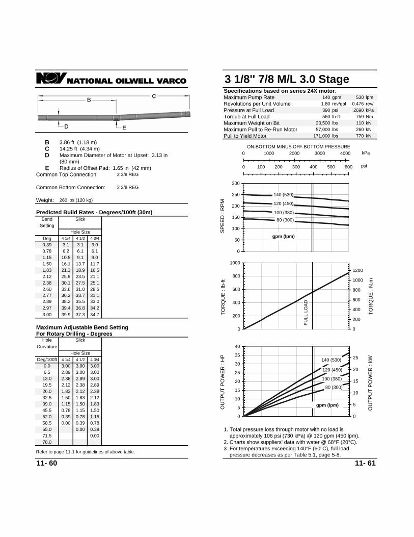
3 1/8'' 7/8 M/L 3.0 StageSpecifications based on series 24X motor.Maximum Pump Rate 140 gpm 530 lpmRevolutions per Unit Volume 1.80 rev/gal 0.476 rev/lPressure at Full Load 390 psi 2690 kPaTorque at Full Load 560 lb-ft 759 NmMaximum Weight on Bit 23,500 lbs 110 kNMaximum Pull to Re-Run Motor 57,000 lbs 260 kNPull to Yield Motor 171,000 lbs 770 kN
B 3.86 ft (1.18 m)C 14.25 ft (4.34 m)D Maximum Diameter of Motor at Upset: 3.13 in
(80 mm)E Radius of Offset Pad: 1.65 in (42 mm)
Common Top Connection: 2 3/8 REG
Common Bottom Connection: 2 3/8 REG
Weight: 260 lbs (120 kg)
11- 60 11- 61
45.5 0.78 1.15 1.50
3. For temperatures exceeding 140°F (60°C), full load pressure decreases as per Table 5.1, page 5-8.Refer to page 11-1 for guidelines of above table.
52.0 0.39 0.78 1.15
78.0 2. Charts show suppliers' data with water @ 68°F (20°C). approximately 106 psi (730 kPa) @ 120 gpm (450 lpm).1. Total pressure loss through motor with no load is
0.00
39.0 1.15 1.50 1.83
13.0 2.38 2.89 3.00
1.83 2.1226.0 1.8332.5 1.50
2.12 2.3819.5 2.12 2.38 2.89
6.5 2.89 3.00 3.00
Curvature
Maximum Adjustable Bend Setting
3.00 39.9 37.3 34.72.97 39.4 36.8 34.22.89 38.2 35.5 33.02.77 36.3 33.7 31.12.60 33.6 31.0 28.52.38 30.1 27.5 25.12.12 25.9 23.5 21.11.83 21.3 18.9 16.51.50 16.1 13.7 11.71.15 10.5 9.1 9.00.78 6.2 6.1 6.10.39 3.1 3.1 3.0
58.5 0.00 0.39 0.78
71.565.0 0.00 0.39
Slick
0.0 3.00 3.00 3.00
Hole SizeDeg/100ft 4 1/4 4 1/2 4 3/4
For Rotary Drilling - DegreesHole Slick
Hole SizeDeg 4 1/4 4 1/2 4 3/4
Predicted Build Rates - Degrees/100ft (30m)
SettingBend 80 (300)
100 (380)
120 (450)
140 (530)
0
50
100
150
200
250
300
SPEE
D :
RPM
gpm (lpm)
kPa0 1000 2000 3000 4000ON-BOTTOM MINUS OFF-BOTTOM PRESSURE
psi0 100 200 300 400 500 600
FULL
LO
AD
0
200
400
600
800
1000
TOR
QU
E : l
b-ft
0
200
400
600
800
1000
1200
TOR
QU
E : N
.m
80 (300)
100 (380)
120 (450)
140 (530)
0
5
10
15
20
25
30
35
40
OU
TPU
T PO
WER
: H
P
0
5
10
15
20
25
OU
TPU
T PO
WER
: kW
gpm (lpm)

3 1/8'' 7/8 M/L 4.0 StageSpecifications based on series 24X motor.Maximum Pump Rate 110 gpm 420 lpmRevolutions per Unit Volume 3.68 rev/gal 0.972 rev/lPressure at Full Load 520 psi 3580 kPaTorque at Full Load 340 lb-ft 461 NmMaximum Weight on Bit 23,500 lbs 110 kNMaximum Pull to Re-Run Motor 57,000 lbs 260 kNPull to Yield Motor 171,000 lbs 770 kN
B 3.86 ft (1.18 m)C 11.58 ft (3.53 m)D Maximum Diameter of Motor at Upset: 3.13 in
(80 mm)E Radius of Offset Pad: 1.65 in (42 mm)
Common Top Connection: 2 3/8 REG
Common Bottom Connection: 2 3/8 REG
Weight: 210 lbs (100 kg)
11- 62 11- 63
Predicted Build Rates - Degrees/100ft (30m)
SettingBend
Hole SizeDeg 4 1/4 4 1/2 4 3/4
For Rotary Drilling - DegreesHole Slick
Hole SizeDeg/100ft 4 1/4 4 1/2 4 3/4
0.0 3.00 3.00 3.00
Slick
60.555.0 0.00 0.3949.5 0.00 0.39 0.78
0.39 2.8 2.7 2.70.78 5.5 5.5 5.41.15 9.3 8.1 8.01.50 14.2 12.1 10.41.83 18.9 16.8 14.72.12 23.0 20.8 18.72.38 26.7 24.5 22.32.60 29.8 27.5 25.42.77 32.2 29.9 27.72.89 33.9 31.6 29.42.97 35.0 32.7 30.53.00 35.4 33.1 30.9
Maximum Adjustable Bend Setting
Curvature
5.5 2.89 3.00 3.00
16.5 2.12 2.38 2.892.12 2.3822.0 1.83
27.5 1.50 1.83 2.12
11.0 2.60 2.89 3.00
33.0 1.15 1.50 1.83
0.002. Charts show suppliers' data with water @ 68°F (20°C). approximately 120 psi (830 kPa) @ 90 gpm (340 lpm).1. Total pressure loss through motor with no load is
44.0 0.39 0.78 1.15
66.03. For temperatures exceeding 140°F (60°C), full load pressure decreases as per Table 5.1, page 5-8.Refer to page 11-1 for guidelines of above table.
38.5 0.78 1.15 1.50
70 (260)
80 (300) 90 (340)
110 (420)
050
100150200250300350400450
SPEE
D :
RPM
gpm (lpm)
kPa0 1000 2000 3000 4000 5000ON-BOTTOM MINUS OFF-BOTTOM PRESSURE
psi0 200 400 600 800
FULL
LO
AD
0
100
200
300
400
500
600
TOR
QU
E : l
b-ft
0
100
200
300
400
500
600
700
800
TOR
QU
E : N
.m
70 (260)
80 (300)
90 (340)
110 (420)
0
5
10
15
20
25
30
35
OU
TPU
T PO
WER
: H
P
0
5
10
15
20
25
OU
TPU
T PO
WER
: kW
gpm (lpm)

3 3/8'' 1/2 H/S 5.5 StageSpecifications based on series 4 motor.Maximum Pump Rate 100 gpm 380 lpmRevolutions per Unit Volume 6.50 rev/gal 1.717 rev/lPressure at Full Load 720 psi 4960 kPaTorque at Full Load 330 lb-ft 447 NmMaximum Weight on Bit 22,000 lbs 100 kNMaximum Pull to Re-Run Motor 60,000 lbs 270 kN
A 1.3 ft (0.4 m) Pull to Yield Motor 144,000 lbs 650 kNB 5.2 ft (1.58 m)C 21.9 ft (6.68 m)D Maximum Diameter of Motor at Upset: 3.38 in
(86 mm)E Radius of Offset Pad: 1.81 in (46 mm)
Common Top Connection: 2 3/8 REG 2 7/8 REG2 3/8 IF
Common Bottom Connection: 2 3/8 REG 2 7/8 REG
Weight: 470 lbs (210 kg)
11- 64 11- 65
28.0 0.78 0.78 1.15
42.0
24.5 1.15 1.15 1.50
2. Charts show suppliers' data with water @ 68°F (20°C). approximately 120 psi (830 kPa) @ 75 gpm (280 lpm).1. Total pressure loss through motor with no load is
0.78 0.780.00 0.000.39 0.39
2.12 1.83
0.78
0.00 0.00 0.00 0.0021.0 1.50 1.50 1.83
0.781.83 1.50
7.0 3.00 3.00 3.00
14.0 2.38 1.15
3.00 2.38 2.60 2.772.60 2.772.12 2.38
2.12 2.12 0.78 0.7817.5 1.83
1.50 1.502.38 2.60 1.50 1.15
1.83 1.831.15
10.5 2.60 2.89 3.00
3.5 3.00 3.00 3.00
Stabilizer Stabilizer
2.89 3.00 3.00
Hole Size Hole Size4 1/4 4 1/2 4 3/4
Curvature
21.122.9
2.12 2.12
Maximum Adjustable Bend Setting
Single Two
3.003.00 3.00
21.7 20.93.00 22.9 21.9 20.9 22.9 21.9 20.9 21.9
21.0 20.42.97 22.7 21.7 20.7 22.7 21.7 20.7 22.7
20.0 19.52.89 22.0 21.0 20.0 22.0 21.0 20.0 22.0
18.6 18.32.77 21.0 20.0 19.1 21.0 20.0 19.5 21.0
16.8 16.82.60 19.6 18.6 17.7 19.6 18.6 18.3 19.6
14.8 15.02.38 17.8 16.8 15.9 17.8 16.8 16.8 17.8
12.8 12.82.12 15.6 14.7 13.7 15.6 14.7 15.0 15.6
10.3 10.31.83 13.2 12.3 11.3 13.2 12.8 12.9 13.2
7.6 7.61.50 10.5 9.6 8.6 10.5 10.4 10.6 10.5
4.8 4.81.15 7.6 6.7 5.8 7.8 8.0 8.2 7.6
1.8 1.80.78 4.5 3.6 3.2 5.2 5.4 5.6 4.8
2.4 2.6 2.8 1.80.39 1.6 1.6 1.6
Two
4 1/2 4 3/4
31.5 0.39 0.39 0.78
38.535.0 0.00 0.00 0.39
0.00
Refer to page 11-1 for guidelines of above table.
Single
0.0 3.00 3.00 3.004 1/4 4 1/2 4 3/4
Hole SizeDeg/100ft 4 1/4 4 1/2 4 3/4
For Rotary Drilling - DegreesHole Slick
Hole Size Hole Size4 1/4 4 1/2 4 3/4 4 1/4Deg 4 1/4 4 1/2 4 3/4
Bend
Hole Size
Slick
3. For temperatures exceeding 140°F (60°C), full load pressure decreases as per Table 5.1, page 5-8.
Predicted Build Rates - Degrees/100ft (30m)
Setting Stabilizer Stabilizers
25 (90)
50 (190)
75 (280)
100 (380)
0
100
200
300
400
500
600
700
SPEE
D :
RPM
gpm (lpm)
kPa0 2000 4000 6000 8000ON-BOTTOM MINUS OFF-BOTTOM PRESSURE
psi0 200 400 600 800 1000 1200
FULL
LO
AD
0
100
200
300
400
500
600
TOR
QU
E : l
b-ft
0
100
200
300
400
500
600
700
800
TOR
QU
E : N
.m
25 (90)
50 (190)
75 (280)
100 (380)
05
101520253035404550
OU
TPU
T PO
WER
: H
P
0
5
10
15
20
25
30
35
OU
TPU
T PO
WER
: kW
gpm (lpm)

3 3/8'' 4/5 M/L 5.0 StageSpecifications based on series 4 motor.Maximum Pump Rate 110 gpm 420 lpmRevolutions per Unit Volume 3.18 rev/gal 0.840 rev/lPressure at Full Load 650 psi 4480 kPaTorque at Full Load 550 lb-ft 745 NmMaximum Weight on Bit 22,000 lbs 100 kNMaximum Pull to Re-Run Motor 60,000 lbs 270 kN
A 1.3 ft (0.4 m) Pull to Yield Motor 144,000 lbs 650 kNB 5.2 ft (1.58 m)C 16.9 ft (5.15 m)D Maximum Diameter of Motor at Upset: 3.38 in
(86 mm)E Radius of Offset Pad: 1.81 in (46 mm)
Common Top Connection: 2 3/8 REG 2 7/8 REG2 3/8 IF
Common Bottom Connection: 2 3/8 REG 2 7/8 REG
Weight: 360 lbs (160 kg)
11- 66 11- 67
Predicted Build Rates - Degrees/100ft (30m)
Setting Stabilizer StabilizersBend
Hole SizeDeg 4 1/4 4 1/2 4 3/4
Hole Size Hole Size4 1/4 4 1/2 4 3/4 4 1/4
For Rotary Drilling - DegreesHole Slick
4 1/4 4 1/2 4 3/4Hole Size
Deg/100ft 4 1/4 4 1/2 4 3/40.0 3.00 3.00 3.00
Slick Single
Refer to page 11-1 for guidelines of above table.
44.040.0 0.00 0.0036.0 0.00 0.39 0.39
Two
4 1/2 4 3/40.39 2.0 2.0 2.3 3.1 3.4 3.7 2.3 2.3 2.30.78 5.7 4.6 4.0 6.3 6.6 7.0 5.6 5.6 5.71.15 9.5 8.4 7.2 9.5 9.7 10.0 9.0 9.0 9.01.50 13.1 12.0 10.8 13.1 12.6 12.9 13.1 12.2 12.21.83 16.6 15.3 14.2 16.6 15.3 15.7 16.6 15.2 15.22.12 19.5 18.3 17.1 19.5 18.3 18.1 19.5 18.3 17.82.38 22.2 21.0 19.8 22.2 21.0 19.8 22.2 21.0 20.22.60 24.5 23.2 22.0 24.5 23.2 22.0 24.5 23.2 22.02.77 26.3 25.0 23.7 26.5 25.0 23.7 26.5 25.0 23.72.89 27.5 26.2 24.9 27.9 26.2 24.9 27.9 26.2 24.92.97 28.3 27.0 25.8 28.8 27.0 25.8 28.8 27.0 25.83.00 28.6 27.3 26.1 29.2 27.3 26.1 27.3
1.83 1.83
Maximum Adjustable Bend Setting
Single Two
3.002.60 2.89
26.129.2
Curvature Stabilizer Stabilizer
2.38 2.60 2.77
Hole Size Hole Size4 1/4 4 1/2 4 3/4
4.0 3.00 3.00 3.00
12.0 2.12 2.38 2.77 1.15 1.152.12 2.38 1.15 0.78
1.50 1.150.78 0.7816.0 1.83
20.0 1.50 1.83 1.83 0.78 0.39
2.12 2.381.83 2.12
2.60 2.12 2.12 2.388.0 2.60 2.89 3.00 1.83 1.50
0.78 0.391.50 1.15
0.39 0.00 0.00 0.0024.0 1.15 1.50 1.50 0.00 0.00 0.00
0.002. Charts show suppliers' data with water @ 68°F (20°C). approximately 150 psi (1030 kPa) @ 85 gpm (320 lpm).1. Total pressure loss through motor with no load is
28.0 0.78 1.15 1.1532.0 0.39 0.78 0.78
48.03. For temperatures exceeding 140°F (60°C), full load pressure decreases as per Table 5.1, page 5-8.
35 (130)
60 (230)
85 (320)
110 (420)
0
50
100
150
200
250
300
350
400
SPEE
D :
RPM
gpm (lpm)
kPa0 2000 4000 6000 8000ON-BOTTOM MINUS OFF-BOTTOM PRESSURE
psi0 200 400 600 800 1000 1200
FULL
LO
AD
0
200
400
600
800
1000
1200
TOR
QU
E : l
b-ft
0
200
400
600
800
1000
1200
1400
1600
TOR
QU
E : N
.m
35 (130)
60 (230)
85 (320)
110 (420)
0
5
10
15
20
25
30
35
40
45
OU
TPU
T PO
WER
: H
P
0
5
10
15
20
25
30
OU
TPU
T PO
WER
: kW
gpm (lpm)

3 3/8'' 7/8 M/L 3.0 StageSpecifications based on series 4 motor.Maximum Pump Rate 110 gpm 420 lpmRevolutions per Unit Volume 1.64 rev/gal 0.433 rev/lPressure at Full Load 390 psi 2690 kPaTorque at Full Load 610 lb-ft 827 NmMaximum Weight on Bit 22,000 lbs 100 kNMaximum Pull to Re-Run Motor 60,000 lbs 270 kN
A 1.3 ft (0.4 m) Pull to Yield Motor 144,000 lbs 650 kNB 5.2 ft (1.58 m)C 17.5 ft (5.33 m)D Maximum Diameter of Motor at Upset: 3.38 in
(86 mm)E Radius of Offset Pad: 1.81 in (46 mm)
Common Top Connection: 2 3/8 REG 2 7/8 REG2 3/8 IF
Common Bottom Connection: 2 3/8 REG 2 7/8 REG
Weight: 370 lbs (170 kg)
11- 68 11- 69
Predicted Build Rates - Degrees/100ft (30m)
Setting Stabilizer StabilizersBend
Hole SizeDeg 4 1/4 4 1/2 4 3/4
Hole Size Hole Size4 1/4 4 1/2 4 3/4 4 1/4
For Rotary Drilling - DegreesHole Slick
4 1/4 4 1/2 4 3/4Hole Size
Deg/100ft 4 1/4 4 1/2 4 3/40.0 3.00 3.00 3.00
Slick Single
Refer to page 11-1 for guidelines of above table.
44.040.0 0.00 0.0036.0 0.00 0.39 0.39
Two
4 1/2 4 3/40.39 2.0 1.9 2.2 2.9 3.3 3.6 2.2 2.2 2.20.78 5.5 4.4 3.9 6.1 6.4 6.7 5.5 5.5 5.51.15 9.2 8.1 7.0 9.2 9.4 9.7 8.8 8.8 8.81.50 12.7 11.6 10.4 12.7 12.3 12.6 12.7 11.9 11.91.83 16.0 14.8 13.7 16.0 14.8 15.2 16.0 14.8 14.82.12 18.9 17.7 16.6 18.9 17.7 17.6 18.9 17.7 17.42.38 21.5 20.3 19.1 21.5 20.3 19.7 21.5 20.3 19.72.60 23.7 22.5 21.3 23.7 22.5 21.3 23.7 22.5 21.42.77 25.4 24.2 23.0 25.5 24.2 23.0 25.5 24.2 23.02.89 26.6 25.4 24.1 26.8 25.4 24.1 26.8 25.4 24.12.97 27.4 26.1 24.9 27.8 26.1 24.9 27.8 26.1 24.93.00 27.7 26.4 25.2 28.1 26.4 25.2 26.4
1.83 1.83
Maximum Adjustable Bend Setting
Single Two
3.002.60 2.89
25.228.1
Curvature Stabilizer Stabilizer
2.38 2.60 2.89
Hole Size Hole Size4 1/4 4 1/2 4 3/4
4.0 3.00 3.00 3.00
12.0 2.12 2.38 2.77 1.15 1.502.12 2.38 1.15 0.78
1.50 1.150.78 1.1516.0 1.83
20.0 1.50 1.83 1.83 0.78 0.39
2.12 2.381.83 2.12
2.12 2.12 2.38 2.388.0 2.60 2.89 3.00 1.83 1.50
0.78 0.391.50 1.15
0.39 0.00 0.00 0.0024.0 1.15 1.50 1.50 0.00 0.00 0.00
2. Charts show suppliers' data with water @ 68°F (20°C). approximately 130 psi (900 kPa) @ 85 gpm (320 lpm).1. Total pressure loss through motor with no load is
28.0 0.78 0.78 1.1532.0 0.39 0.78 0.78
48.03. For temperatures exceeding 140°F (60°C), full load pressure decreases as per Table 5.1, page 5-8.
35 (130)
60 (230)
85 (320)
110 (420)
020406080
100120140160180
SPEE
D :
RPM
gpm (lpm)
kPa0 1000 2000 3000 4000 5000ON-BOTTOM MINUS OFF-BOTTOM PRESSURE
psi0 200 400 600 800
FULL
LO
AD
0
200
400
600
800
1000
1200
1400
TOR
QU
E : l
b-ft
020040060080010001200140016001800
TOR
QU
E : N
.m
35 (130)
60 (230)
85 (320)
110 (420)
0
5
10
15
20
25
30
OU
TPU
T PO
WER
: H
P
0
5
10
15
20
OU
TPU
T PO
WER
: kW
gpm (lpm)

3 1/2'' 4/5 M/L 4.0 StageSpecifications based on series 14 motor.Maximum Pump Rate 160 gpm 610 lpmRevolutions per Unit Volume 2.69 rev/gal 0.711 rev/lPressure at Full Load 520 psi 3580 kPaTorque at Full Load 590 lb-ft 799 NmMaximum Weight on Bit 28,000 lbs 130 kNMaximum Pull to Re-Run Motor 60,000 lbs 270 kNPull to Yield Motor 183,000 lbs 820 kN
B 4.5 ft (1.37 m)C 15.6 ft (4.75 m)D Maximum Diameter of Motor at Upset: 3.5 in
(89 mm)E Radius of Offset Pad: 1.75 in (44 mm)
Common Top Connection: 2 3/8 REG 2 7/8 REG2 3/8 IF
Common Bottom Connection: 2 7/8 REG 2 3/8 REG
Weight: 360 lbs (160 kg)
11- 70 11- 71
3. For temperatures exceeding 140°F (60°C), full load pressure decreases as per Table 5.1, page 5-8.
28.0 0.39 0.78 0.78
42.0
24.5 0.78 0.78 1.15
2. Charts show suppliers' data with water @ 68°F (20°C). approximately 230 psi (1580 kPa) @ 130 gpm (490 lpm).1. Total pressure loss through motor with no load is
0.00
21.0 1.15 1.15 1.50
7.0 2.12 2.38 2.77
1.50 1.8314.0 1.5017.5 1.15
1.83 2.1210.5 1.83 2.12 2.38
3.5 2.60 2.77 3.00
Curvature
Maximum Adjustable Bend Setting
3.00 27.7 26.2 24.82.97 27.3 25.9 24.52.89 26.5 25.1 23.72.77 25.3 23.8 22.52.60 23.5 22.1 20.72.38 21.2 19.8 18.42.12 18.5 17.1 15.81.83 15.4 14.1 12.81.50 12.0 10.7 9.41.15 8.3 7.0 5.90.78 4.4 4.1 4.00.39 2.0 2.0 2.0
31.5 0.00 0.39 0.39
38.535.0 0.00 0.39
Refer to page 11-1 for guidelines of above table.
Slick
0.0 2.89 3.00 3.00
Hole SizeDeg/100ft 4 1/4 4 1/2 4 3/4
For Rotary Drilling - DegreesHole Slick
Hole SizeDeg 4 1/4 4 1/2 4 3/4
Predicted Build Rates - Degrees/100ft (30m)
SettingBend
70 (260)
100 (380)
130 (490)
160 (610)
050
100150200250300350400450
SPEE
D :
RPM
gpm (lpm)
kPa0 1000 2000 3000 4000 5000 6000ON-BOTTOM MINUS OFF-BOTTOM PRESSURE
psi0 200 400 600 800 1000
FULL
LO
AD
0
200
400
600
800
1000
1200
TOR
QU
E : l
b-ft
0
200
400
600
800
1000
1200
1400
1600
TOR
QU
E : N
.m
70 (260)
100 (380)
130 (490)
160 (610)
0
10
20
30
40
50
60
70
OU
TPU
T PO
WER
: H
P
0
10
20
30
40
50
OU
TPU
T PO
WER
: kW
gpm (lpm)

3 1/2'' 5/6 M/L 2.0 StageSpecifications based on series 14 motor.Maximum Pump Rate 160 gpm 610 lpmRevolutions per Unit Volume 2.44 rev/gal 0.645 rev/lPressure at Full Load 260 psi 1790 kPaTorque at Full Load 290 lb-ft 393 NmMaximum Weight on Bit 28,000 lbs 130 kNMaximum Pull to Re-Run Motor 60,000 lbs 270 kNPull to Yield Motor 183,000 lbs 820 kN
B 4.5 ft (1.37 m)C 11.05 ft (3.37 m)D Maximum Diameter of Motor at Upset: 3.5 in
(89 mm)E Radius of Offset Pad: 1.75 in (44 mm)
Common Top Connection: 2 3/8 REG 2 7/8 REG2 3/8 IF
Common Bottom Connection: 2 3/8 REG 2 7/8 REG
Weight: 250 lbs (110 kg)
11- 72 11- 73
36.0 0.00 0.39 0.78
54.0
31.5 0.39 0.78 1.15
2. Charts show suppliers' data with water @ 68°F (20°C). approximately 220 psi (1520 kPa) @ 130 gpm (490 lpm).1. Total pressure loss through motor with no load is
27.0 0.78 1.15 1.50
9.0 1.83 2.12 2.38
18.0 1.151.15 1.5022.5 1.151.50 1.83
13.5 1.50 1.83 2.12
4.5 2.12 2.38 2.77
Curvature
Maximum Adjustable Bend Setting
3.00 38.5 36.4 34.42.97 38.1 36.0 34.02.89 36.9 34.8 32.82.77 35.2 33.1 31.12.60 32.7 30.7 28.72.38 29.5 27.5 25.52.12 25.7 23.7 21.81.83 21.5 19.6 17.71.50 16.7 14.8 13.01.15 11.6 9.7 8.20.78 6.2 5.6 5.60.39 2.9 2.8 2.8
40.5 0.00 0.39 0.39
49.545.0 0.00 0.39
0.00
Refer to page 11-1 for guidelines of above table.
0.0 2.38 2.77 3.00
Hole SizeDeg/100ft 4 1/4 4 1/2 4 3/4
For Rotary Drilling - DegreesHole Slick
Deg 4 1/4 4 1/2 4 3/4
Bend
Hole Size
Slick
3. For temperatures exceeding 140°F (60°C), full load pressure decreases as per Table 5.1, page 5-8.
Predicted Build Rates - Degrees/100ft (30m)
Setting 70 (260)
100 (380)
130 (490)
160 (610)
050
100150200250300350400450
SPEE
D :
RPM
gpm (lpm)
kPa0 500 1000 1500 2000 2500ON-BOTTOM MINUS OFF-BOTTOM PRESSURE
psi0 100 200 300 400
FULL
LO
AD
050
100150200250300350400450500
TOR
QU
E : l
b-ft
0
100
200
300
400
500
600
TOR
QU
E : N
.m
70 (260)
100 (380)
130 (490)
160 (610)
0
5
10
15
20
25
30
35
OU
TPU
T PO
WER
: H
P
0
5
10
15
20
25
OU
TPU
T PO
WER
: kW
gpm (lpm)

3 1/2'' 5/6 M/L 2.0 StageSpecifications based on series 20 motor.Maximum Pump Rate 160 gpm 610 lpmRevolutions per Unit Volume 2.44 rev/gal 0.645 rev/lPressure at Full Load 260 psi 1790 kPaTorque at Full Load 290 lb-ft 393 NmMaximum Weight on Bit 28,000 lbs 130 kNMaximum Pull to Re-Run Motor 60,000 lbs 270 kN
A 0.9 ft (0.27 m) Pull to Yield Motor 143,000 lbs 640 kNB 2.6 ft (0.79 m)C 9.05 ft (2.76 m)D Maximum Diameter of Motor at Upset: 4.75 in
(121 mm)E Radius of Offset Pad: 1.81 in (46 mm)
Common Top Connection: 2 3/8 REG 2 7/8 REG2 3/8 IF
Common Bottom Connection: 2 3/8 REG 2 7/8 REG
Weight: 210 lbs (90 kg)
Bend Slick Single Two
1.04
2.833.06
3.94
Deg/100ft0.0
36.0
72.0
11- 74 11- 75
3. For temperatures exceeding 140°F (60°C), full load pressure decreases as per Table 5.1, page 5-8.
45.342.3
Maximum Adjustable Bend Setting
2. Charts show suppliers' data with water @ 68°F (20°C). approximately 170 psi (1170 kPa) @ 130 gpm (490 lpm).1. Total pressure loss through motor with no load is
Refer to page 11-1 for guidelines of above table.
39.135.5
55.255.054.453.351.9
35.531.7
23.419.0
2.94 3/4
55.255.054.453.351.950.147.845.3
14.111.48.75.8
52.352.051.350.0
66.060.054.0
18.012.0
TwoCurvature Stabilizer Stabilizer
SingleHole Slick
4.00
0.000.350.690.691.041.371.692.00
0.69
1.692.00
3.86
3.98
2.292.573.063.284 3/4
0.000.35
4 3/4
1.04
Hole Size
3.76 48.4
0.000.350.691.041.374 3/4
6.0
24.0
50.13.63 46.2
For Rotary Drilling - Degrees
Hole Size
31.72.29 24.0
47.83.46 43.43.28 40.4
42.339.1
4 3/4 4 3/4
27.7 27.3
14.49.6
22.317.111.87.2
36.732.9
Predicted Build Rates - Degrees/100ft (30m)
Hole SizeDeg
Hole Size Hole Size
48.0
Stabilizers
3.60.350.69
4.9
StabilizerSetting
Hole Size
30.0
1.691.37
2.00 19.1
2.57 28.6
42.0
70 (260)
100 (380)
130 (490)
160 (610)
0
50
100
150
200
250
300
350
400
SPEE
D :
RPM
gpm (lpm)
kPa0 500 1000 1500 2000 2500ON-BOTTOM MINUS OFF-BOTTOM PRESSURE
psi0 100 200 300 400
FULL
LO
AD
050
100150200250300350400450500
TOR
QU
E : l
b-ft
0
100
200
300
400
500
600
TOR
QU
E : N
.m
70 (260)
100 (380)
130 (490)
160 (610)
0
5
10
15
20
25
30
35
OU
TPU
T PO
WER
: H
P
0
5
10
15
20
25
OU
TPU
T PO
WER
: kW
gpm (lpm)
4 Degree Adjustable Housing
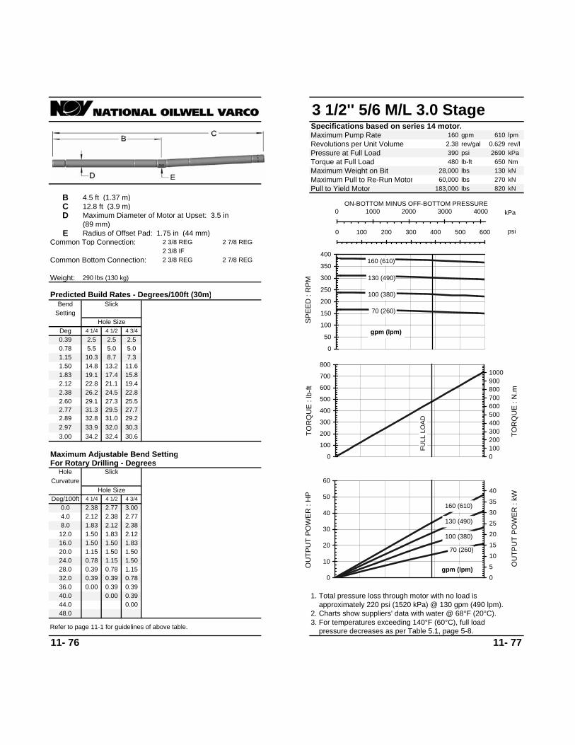
3 1/2'' 5/6 M/L 3.0 StageSpecifications based on series 14 motor.Maximum Pump Rate 160 gpm 610 lpmRevolutions per Unit Volume 2.38 rev/gal 0.629 rev/lPressure at Full Load 390 psi 2690 kPaTorque at Full Load 480 lb-ft 650 NmMaximum Weight on Bit 28,000 lbs 130 kNMaximum Pull to Re-Run Motor 60,000 lbs 270 kNPull to Yield Motor 183,000 lbs 820 kN
B 4.5 ft (1.37 m)C 12.8 ft (3.9 m)D Maximum Diameter of Motor at Upset: 3.5 in
(89 mm)E Radius of Offset Pad: 1.75 in (44 mm)
Common Top Connection: 2 3/8 REG 2 7/8 REG2 3/8 IF
Common Bottom Connection: 2 3/8 REG 2 7/8 REG
Weight: 290 lbs (130 kg)
11- 76 11- 77
3. For temperatures exceeding 140°F (60°C), full load pressure decreases as per Table 5.1, page 5-8.
32.0 0.39 0.39 0.78
48.0
28.0 0.39 0.78 1.15
2. Charts show suppliers' data with water @ 68°F (20°C). approximately 220 psi (1520 kPa) @ 130 gpm (490 lpm).1. Total pressure loss through motor with no load is
0.00
24.0 0.78 1.15 1.50
8.0 1.83 2.12 2.38
1.50 1.5016.0 1.5020.0 1.15
1.50 1.8312.0 1.50 1.83 2.12
4.0 2.12 2.38 2.77
Curvature
Maximum Adjustable Bend Setting
3.00 34.2 32.4 30.62.97 33.9 32.0 30.32.89 32.8 31.0 29.22.77 31.3 29.5 27.72.60 29.1 27.3 25.52.38 26.2 24.5 22.82.12 22.8 21.1 19.41.83 19.1 17.4 15.81.50 14.8 13.2 11.61.15 10.3 8.7 7.30.78 5.5 5.0 5.00.39 2.5 2.5 2.5
36.0 0.00 0.39 0.39
44.040.0 0.00 0.39
Refer to page 11-1 for guidelines of above table.
Slick
0.0 2.38 2.77 3.00
Hole SizeDeg/100ft 4 1/4 4 1/2 4 3/4
For Rotary Drilling - DegreesHole Slick
Hole SizeDeg 4 1/4 4 1/2 4 3/4
Predicted Build Rates - Degrees/100ft (30m)
SettingBend
70 (260)
100 (380)
130 (490)
160 (610)
0
50
100
150
200
250
300
350
400
SPEE
D :
RPM
gpm (lpm)
kPa0 1000 2000 3000 4000ON-BOTTOM MINUS OFF-BOTTOM PRESSURE
psi0 100 200 300 400 500 600
FULL
LO
AD
0
100
200
300
400
500
600
700
800
TOR
QU
E : l
b-ft
01002003004005006007008009001000
TOR
QU
E : N
.m
70 (260)
100 (380)
130 (490)
160 (610)
0
10
20
30
40
50
60
OU
TPU
T PO
WER
: H
P
0
5
10
15
20
25
30
35
40
OU
TPU
T PO
WER
: kW
gpm (lpm)

3 1/2'' 7/8 M/L 3.8 StageSpecifications based on series 14 motor.Maximum Pump Rate 130 gpm 490 lpmRevolutions per Unit Volume 2.31 rev/gal 0.610 rev/lPressure at Full Load 490 psi 3380 kPaTorque at Full Load 810 lb-ft 1098 NmMaximum Weight on Bit 28,000 lbs 130 kNMaximum Pull to Re-Run Motor 60,000 lbs 270 kNPull to Yield Motor 183,000 lbs 820 kN
B 4.5 ft (1.37 m)C 17.3 ft (5.27 m)D Maximum Diameter of Motor at Upset: 3.5 in
(89 mm)E Radius of Offset Pad: 1.75 in (44 mm)
Common Top Connection: 2 3/8 REG 2 7/8 REG2 3/8 IF
Common Bottom Connection: 2 3/8 REG 2 7/8 REG
Weight: 400 lbs (180 kg)
11- 78 11- 79
Predicted Build Rates - Degrees/100ft (30m)
SettingBend
Hole SizeDeg 4 1/4 4 1/2 4 3/4
For Rotary Drilling - DegreesHole Slick
Hole SizeDeg/100ft 4 1/4 4 1/2 4 3/4
0.0 3.00 3.00 3.00
Slick
Refer to page 11-1 for guidelines of above table.
38.535.0 0.00 0.0031.5 0.00 0.39 0.39
0.39 2.0 1.9 1.90.78 4.2 3.9 3.91.15 8.0 6.7 5.71.50 11.5 10.2 9.01.83 14.8 13.5 12.22.12 17.7 16.4 15.12.38 20.3 19.0 17.72.60 22.5 21.2 19.92.77 24.2 22.9 21.52.89 25.4 24.0 22.72.97 26.2 24.8 23.53.00 26.5 25.1 23.8
Maximum Adjustable Bend Setting
Curvature
3.5 2.60 2.89 3.00
10.5 1.83 2.12 2.381.83 2.1214.0 1.50
17.5 1.15 1.50 1.83
7.0 2.38 2.60 2.77
21.0 1.15 1.15 1.50
0.002. Charts show suppliers' data with water @ 68°F (20°C). approximately 160 psi (1100 kPa) @ 110 gpm (420 lpm).1. Total pressure loss through motor with no load is
24.5 0.78 0.78 1.1528.0 0.39 0.39 0.78
42.03. For temperatures exceeding 140°F (60°C), full load pressure decreases as per Table 5.1, page 5-8.
70 (260)
90 (340)
110 (420)
130 (490)
0
50
100
150
200
250
300
350
SPEE
D :
RPM
gpm (lpm)
kPa0 1000 2000 3000 4000 5000ON-BOTTOM MINUS OFF-BOTTOM PRESSURE
psi0 200 400 600 800
FULL
LO
AD
0
200
400
600
800
1000
1200
1400
TOR
QU
E : l
b-ft
020040060080010001200140016001800
TOR
QU
E : N
.m
70 (260)
90 (340)
110 (420)
130 (490)
0
5
10
15
20
25
30
35
40
45
OU
TPU
T PO
WER
: H
P
0
5
10
15
20
25
30
OU
TPU
T PO
WER
: kW
gpm (lpm)

3 1/2'' 7/8 M/L 4.3 StageSpecifications based on series 14 motor.Maximum Pump Rate 110 gpm 420 lpmRevolutions per Unit Volume 1.85 rev/gal 0.489 rev/lPressure at Full Load 560 psi 3860 kPaTorque at Full Load 800 lb-ft 1084 NmMaximum Weight on Bit 28,000 lbs 130 kNMaximum Pull to Re-Run Motor 60,000 lbs 270 kNPull to Yield Motor 183,000 lbs 820 kN
B 4.5 ft (1.37 m)C 17.44 ft (5.32 m)D Maximum Diameter of Motor at Upset: 3.5 in
(89 mm)E Radius of Offset Pad: 1.75 in (44 mm)
Common Top Connection: 3 3/8 REG 3 7/8 REG3 3/8 IF
Common Bottom Connection: 3 3/8 REG 3 7/8 REG
Weight: 400 lbs (180 kg)
11- 80 11- 81
3. For temperatures exceeding 140°F (60°C), full load pressure decreases as per Table 5.1, page 5-8.Refer to page 11-1 for guidelines of above table.
Predicted Build Rates - Degrees/100ft (30m)
SettingSlickBend
Hole SizeDeg 4 1/4 4 1/2 4 3/4
For Rotary Drilling - DegreesHole Slick
Hole SizeDeg/100ft 4 1/4 4 1/2 4 3/4
0.0 3.00 3.00 3.00
38.535.0 0.00 0.00
0.00
31.5 0.00 0.39 0.39
0.39 2.0 2.0 1.90.78 4.2 3.9 3.91.15 8.0 6.7 5.71.50 11.5 10.2 9.01.83 14.8 13.5 12.32.12 17.7 16.4 15.12.38 20.3 19.0 17.72.60 22.5 21.2 19.92.77 24.2 22.9 21.62.89 25.4 24.1 22.82.97 26.2 24.9 23.63.00 26.5 25.2 23.9
Maximum Adjustable Bend Setting
Curvature
3.5 2.60 2.89 3.00
10.5 1.83 2.12 2.381.83 2.1214.0 1.50
17.5 1.15 1.50 1.83
7.0 2.38 2.60 2.77
21.0 1.15 1.15 1.50
2. Charts show suppliers' data with water @ 68°F (20°C). approximately 80 psi (550 kPa) @ 90 gpm (340 lpm).1. Total pressure loss through motor with no load is
24.5 0.78 0.78 1.1528.0 0.39 0.39 0.78
42.0
50 (190)
70 (260)
90 (340)
110 (420)
020406080
100120140160180200220
SPEE
D :
RPM
gpm (lpm)
kPa0 1000 2000 3000 4000 5000ON-BOTTOM MINUS OFF-BOTTOM PRESSURE
psi0 200 400 600 800
FULL
LO
AD
0
200
400
600
800
1000
1200
TOR
QU
E : l
b-ft
0
200
400
600
800
1000
1200
1400
1600
TOR
QU
E : N
.m
50 (190)
70 (260)
90 (340)
110 (420)
0
5
10
15
20
25
30
35
40
45
OU
TPU
T PO
WER
: H
P
0
5
10
15
20
25
30
OU
TPU
T PO
WER
: kWgpm (lpm)

3 3/4'' 1/2 H/S 4.4 StageSpecifications based on series 24 motor.Maximum Pump Rate 140 gpm 530 lpmRevolutions per Unit Volume 4.07 rev/gal 1.075 rev/lPressure at Full Load 570 psi 3930 kPaTorque at Full Load 420 lb-ft 569 NmMaximum Weight on Bit 36,000 lbs 160 kNMaximum Pull to Re-Run Motor 75,000 lbs 340 kNPull to Yield Motor 212,000 lbs 950 kN
B 4 ft (1.22 m)C 20.4 ft (6.22 m)D Maximum Diameter of Motor at Upset: 3.75 in
(95 mm)E Radius of Offset Pad: 2.18 in (55 mm)
Common Top Connection: 2 7/8 REG 3 1/2 REG2 3/8 IF 2 3/8 REG
Common Bottom Connection: 2 7/8 REG 3 1/2 REG2 3/8 REG
Weight: 540 lbs (240 kg)
11- 82 11- 83
28.0 0.39 0.78
42.0
24.5 0.00 0.78 1.15
2. Charts show suppliers' data with water @ 68°F (20°C). approximately 110 psi (760 kPa) @ 115 gpm (440 lpm).1. Total pressure loss through motor with no load is
21.0 0.39 1.15 1.50
7.0 2.12 2.77 3.00
14.0 1.151.50 1.8317.5 0.781.83 2.38
10.5 1.83 2.38 2.60
3.5 2.38 3.00 3.00
Curvature
Maximum Adjustable Bend Setting
3.00 24.1 20.4 18.62.97 23.8 20.1 18.42.89 23.1 19.5 17.72.77 22.1 18.5 16.72.60 20.7 17.1 15.32.38 18.9 15.3 13.52.12 16.7 13.1 11.41.83 14.3 10.7 9.01.50 11.5 8.0 6.31.15 8.5 5.1 4.70.78 5.4 3.2 3.20.39 2.2 1.6 1.6
31.5 0.00 0.39
38.535.0 0.00
Refer to page 11-1 for guidelines of above table.
0.0 3.00 3.00 3.00
Hole SizeDeg/100ft 4 3/4 5 1/2 5 7/8
For Rotary Drilling - DegreesHole Slick
Deg 4 3/4 5 1/2 5 7/8
Bend
Hole Size
Slick
3. For temperatures exceeding 140°F (60°C), full load pressure decreases as per Table 5.1, page 5-8.
Predicted Build Rates - Degrees/100ft (30m)
Setting 65 (250)
90 (340)
115 (440)
140 (530)
0
100
200
300
400
500
600
SPEE
D :
RPM
gpm (lpm)
kPa0 1000 2000 3000 4000 5000 6000ON-BOTTOM MINUS OFF-BOTTOM PRESSURE
psi0 200 400 600 800 1000
FULL
LO
AD
0
100
200
300
400
500
600
700
800
TOR
QU
E : l
b-ft
0
200
400
600
800
1000
TOR
QU
E : N
.m
65 (250)
90 (340)
115 (440)
140 (530)
0
5
10
15
20
25
30
35
40
45
OU
TPU
T PO
WER
: H
P
0
5
10
15
20
25
30
OU
TPU
T PO
WER
: kW
gpm (lpm)

3 3/4'' 3/4 M/L 9.0 StageSpecifications based on series 24 motor.Maximum Pump Rate 150 gpm 570 lpmRevolutions per Unit Volume 5.73 rev/gal 1.514 rev/lPressure at Full Load 1,170 psi 8060 kPaTorque at Full Load 630 lb-ft 854 NmMaximum Weight on Bit 36,000 lbs 160 kNMaximum Pull to Re-Run Motor 75,000 lbs 340 kNPull to Yield Motor 212,000 lbs 950 kN
B 4 ft (1.22 m)C 18 ft (5.49 m)D Maximum Diameter of Motor at Upset: 3.75 in
(95 mm)E Radius of Offset Pad: 2.18 in (55 mm)
Common Top Connection: 2 7/8 REG 3 1/2 REG2 3/8 IF 2 3/8 REG
Common Bottom Connection: 2 7/8 REG 3 1/2 REG2 3/8 REG
Weight: 470 lbs (210 kg)
11- 84 11- 85
Predicted Build Rates - Degrees/100ft (30m)
SettingBend
Hole SizeDeg 4 3/4 5 1/2 5 7/8
For Rotary Drilling - DegreesHole Slick
Hole SizeDeg/100ft 4 3/4 5 1/2 5 7/8
0.0 2.60 3.00 3.00
Slick
Refer to page 11-1 for guidelines of above table.
38.535.0 0.00 0.3931.5 0.39 0.78
0.39 2.6 2.2 1.80.78 6.5 3.7 3.71.15 10.1 6.1 5.41.50 13.5 9.4 7.51.83 16.7 12.6 10.62.12 19.5 15.3 13.32.38 22.1 17.8 15.82.60 24.2 19.9 17.92.77 25.8 21.5 19.52.89 27.0 22.7 20.62.97 27.8 23.4 21.33.00 28.1 23.7 21.6
Maximum Adjustable Bend Setting
Curvature
3.5 2.12 3.00 3.00
10.5 1.50 2.38 2.601.83 2.3814.0 1.15
17.5 0.78 1.50 1.83
7.0 1.83 2.60 3.00
21.0 0.39 1.15 1.50
0.002. Charts show suppliers' data with water @ 68°F (20°C). approximately 260 psi (1790 kPa) @ 125 gpm (470 lpm).1. Total pressure loss through motor with no load is
24.5 0.39 0.78 1.1528.0 0.00 0.78 0.78
42.03. For temperatures exceeding 140°F (60°C), full load pressure decreases as per Table 5.1, page 5-8.
75 (280)
100 (380)
125 (470)
150 (570)
0100200300400500600700800900
SPEE
D :
RPM
gpm (lpm)
kPa0 2000 4000 6000 8000ON-BOTTOM MINUS OFF-BOTTOM PRESSURE
psi0 200 400 600 800 1000 1200 1400
FULL
LO
AD0
100
200
300
400
500
600
700
800
TOR
QU
E : l
b-ft
0
200
400
600
800
1000
TOR
QU
E : N
.m
75 (280)
100 (380)
125 (470)
150 (570)
0
20
40
60
80
100
120
OU
TPU
T PO
WER
: H
P
0
10
20
30
40
50
60
70
80
OU
TPU
T PO
WER
: kW
gpm (lpm)
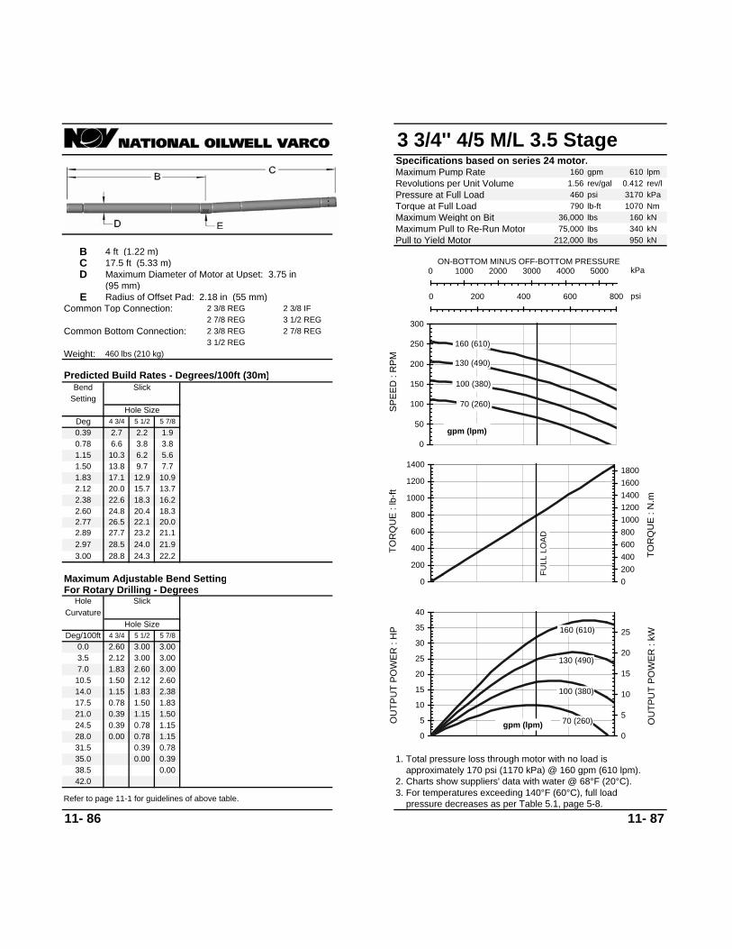
3 3/4'' 4/5 M/L 3.5 StageSpecifications based on series 24 motor.Maximum Pump Rate 160 gpm 610 lpmRevolutions per Unit Volume 1.56 rev/gal 0.412 rev/lPressure at Full Load 460 psi 3170 kPaTorque at Full Load 790 lb-ft 1070 NmMaximum Weight on Bit 36,000 lbs 160 kNMaximum Pull to Re-Run Motor 75,000 lbs 340 kNPull to Yield Motor 212,000 lbs 950 kN
B 4 ft (1.22 m)C 17.5 ft (5.33 m)D Maximum Diameter of Motor at Upset: 3.75 in
(95 mm)E Radius of Offset Pad: 2.18 in (55 mm)
Common Top Connection: 2 3/8 REG 2 3/8 IF2 7/8 REG 3 1/2 REG
Common Bottom Connection: 2 3/8 REG 2 7/8 REG3 1/2 REG
Weight: 460 lbs (210 kg)
11- 86 11- 87
28.0 0.00 0.78 1.15
42.0
24.5 0.39 0.78 1.15
2. Charts show suppliers' data with water @ 68°F (20°C). approximately 170 psi (1170 kPa) @ 160 gpm (610 lpm).1. Total pressure loss through motor with no load is
21.0 0.39 1.15 1.50
7.0 1.83 2.60 3.00
1.50 1.8314.0 1.1517.5 0.78
10.5 1.50 2.12 2.601.83 2.38
3.5 2.12 3.00 3.00
Curvature
Maximum Adjustable Bend Setting
3.00 28.8 24.3 22.22.97 28.5 24.0 21.92.89 27.7 23.2 21.12.77 26.5 22.1 20.02.60 24.8 20.4 18.32.38 22.6 18.3 16.22.12 20.0 15.7 13.71.83 17.1 12.9 10.91.50 13.8 9.7 7.71.15 10.3 6.2 5.60.78 6.6 3.8 3.80.39 2.7 2.2 1.9
31.5 0.39 0.78
38.535.0 0.00 0.39
0.00
0.0 2.60 3.00 3.00
Hole SizeDeg/100ft 4 3/4 5 1/2 5 7/8
For Rotary Drilling - DegreesHole Slick
Deg 4 3/4 5 1/2 5 7/8
Bend
Hole Size
Slick
3. For temperatures exceeding 140°F (60°C), full load pressure decreases as per Table 5.1, page 5-8.Refer to page 11-1 for guidelines of above table.
Predicted Build Rates - Degrees/100ft (30m)
Setting 70 (260)
100 (380)
130 (490)
160 (610)
0
50
100
150
200
250
300
SPEE
D :
RPM
gpm (lpm)
kPa0 1000 2000 3000 4000 5000ON-BOTTOM MINUS OFF-BOTTOM PRESSURE
psi0 200 400 600 800
FULL
LO
AD
0
200
400
600
800
1000
1200
1400
TOR
QU
E : l
b-ft
020040060080010001200140016001800
TOR
QU
E : N
.m
70 (260)
100 (380)
130 (490)
160 (610)
0
5
10
15
20
25
30
35
40
OU
TPU
T PO
WER
: H
P
0
5
10
15
20
25
OU
TPU
T PO
WER
: kW
gpm (lpm)

3 3/4'' 5/6 M/L 5.0 Stage (OS)Specifications based on series 24 motor.Maximum Pump Rate 160 gpm 610 lpmRevolutions per Unit Volume 1.44 rev/gal 0.380 rev/lPressure at Full Load 650 psi 4480 kPaTorque at Full Load 1,100 lb-ft 1491 NmMaximum Weight on Bit 36,000 lbs 160 kNMaximum Pull to Re-Run Motor 75,000 lbs 340 kNPull to Yield Motor 212,000 lbs 950 kN
B 4 ft (1.22 m)C 20.8 ft (6.34 m)D Maximum Diameter of Motor at Upset: 3.75 in
(95 mm)E Radius of Offset Pad: 2.18 in (55 mm)
Common Top Connection: 2 3/8 REG 2 3/8 IF2 7/8 REG 3 1/2 REG
Common Bottom Connection: 2 3/8 REG 2 7/8 REG3 1/2 REG
Weight: 550 lbs (250 kg)
11- 88 11- 89
28.0 0.39 0.78
42.0
24.5 0.00 0.78 1.15
2. Charts show suppliers' data with water @ 68°F (20°C). approximately 200 psi (1380 kPa) @ 130 gpm (490 lpm).1. Total pressure loss through motor with no load is
21.0 0.39 1.15 1.50
7.0 2.12 2.77 3.00
1.50 1.8314.0 1.1517.5 0.78
10.5 1.83 2.38 2.601.83 2.38
3.5 2.38 3.00 3.00
Curvature
Maximum Adjustable Bend Setting
3.00 24.1 20.4 18.62.97 23.8 20.1 18.42.89 23.2 19.5 17.72.77 22.2 18.5 16.72.60 20.7 17.1 15.42.38 18.9 15.3 13.62.12 16.7 13.1 11.41.83 14.3 10.7 9.11.50 11.5 8.0 6.41.15 8.6 5.1 4.70.78 5.4 3.2 3.20.39 2.2 1.6 1.6
31.5 0.00 0.39
38.535.0 0.00
0.0 2.89 3.00 3.00
Hole SizeDeg/100ft 4 3/4 5 1/2 5 7/8
For Rotary Drilling - DegreesHole Slick
Deg 4 3/4 5 1/2 5 7/8
Bend
Hole Size
Slick
3. For temperatures exceeding 140°F (60°C), full load pressure decreases as per Table 5.1, page 5-8.Refer to page 11-1 for guidelines of above table.
Predicted Build Rates - Degrees/100ft (30m)
Setting 70 (260)
100 (380)
130 (490)
160 (610)
0
50
100
150
200
250
SPEE
D :
RPM
gpm (lpm)
kPa0 1000 2000 3000 4000 5000ON-BOTTOM MINUS OFF-BOTTOM PRESSURE
psi0 200 400 600 800
FULL
LO
AD
0
200
400
600
800
1000
1200
1400
TOR
QU
E : l
b-ft
020040060080010001200140016001800
TOR
QU
E : N
.m
70 (260)
100 (380)
130 (490)
160 (610)
0
5
10
15
20
25
30
OU
TPU
T PO
WER
: H
P
0246810121416182022
OU
TPU
T PO
WER
: kW
gpm (lpm)

3 3/4'' 6/7 M/L 3.0 StageSpecifications based on series 24 motor.Maximum Pump Rate 200 gpm 760 lpmRevolutions per Unit Volume 0.80 rev/gal 0.211 rev/lPressure at Full Load 390 psi 2690 kPaTorque at Full Load 1,170 lb-ft 1585 NmMaximum Weight on Bit 36,000 lbs 160 kNMaximum Pull to Re-Run Motor 75,000 lbs 340 kNPull to Yield Motor 212,000 lbs 950 kN
B 4 ft (1.22 m)C 19.21 ft (5.86 m)D Maximum Diameter of Motor at Upset: 3.75 in
(95 mm)E Radius of Offset Pad: 2.18 in (55 mm)
Common Top Connection: 2 3/8 REG 2 3/8 IF2 7/8 REG 3 1/2 REG
Common Bottom Connection: 2 3/8 REG 2 7/8 REG3 1/2 REG
Weight: 500 lbs (230 kg)
11- 90 11- 91
24.5 0.39 0.78 1.15
3. For temperatures exceeding 140°F (60°C), full load pressure decreases as per Table 5.1, page 5-8.Refer to page 11-1 for guidelines of above table.
28.0 0.00 0.39 0.78
42.0 2. Charts show suppliers' data with water @ 68°F (20°C). approximately 145 psi (1000 kPa) @ 160 gpm (610 lpm).1. Total pressure loss through motor with no load is
0.00
21.0 0.39 1.15 1.50
7.0 1.83 2.60 3.00
1.50 1.8314.0 1.1517.5 0.78
1.83 2.3810.5 1.50 2.38 2.60
3.5 2.38 3.00 3.00
Curvature
Maximum Adjustable Bend Setting
3.00 26.5 22.4 20.42.97 26.2 22.1 20.22.89 25.5 21.4 19.42.77 24.4 20.3 18.42.60 22.8 18.8 16.82.38 20.8 16.8 14.92.12 18.4 14.4 12.61.83 15.7 11.8 10.01.50 12.7 8.8 7.01.15 9.4 5.7 5.20.78 6.0 3.5 3.50.39 2.4 1.8 1.8
31.5 0.00 0.39
38.535.0 0.00 0.00
Slick
0.0 2.77 3.00 3.00
Hole SizeDeg/100ft 4 3/4 5 1/2 5 7/8
For Rotary Drilling - DegreesHole Slick
Hole SizeDeg 4 3/4 5 1/2 5 7/8
Predicted Build Rates - Degrees/100ft (30m)
SettingBend
80 (300)
120 (450)
160 (610)
200 (760)
020406080
100120140160180
SPEE
D :
RPM
gpm (lpm)
kPa0 1000 2000 3000 4000ON-BOTTOM MINUS OFF-BOTTOM PRESSURE
psi0 100 200 300 400 500 600
FULL
LO
AD
0
250
500
750
1000
1250
1500
1750
2000
TOR
QU
E : l
b-ft
0
500
1000
1500
2000
2500
TOR
QU
E : N
.m
80 (300)
120 (450)
160 (610)
200 (760)
05
101520253035404550
OU
TPU
T PO
WER
: H
P
0
5
10
15
20
25
30
35
OU
TPU
T PO
WER
: kW
gpm (lpm)

3 3/4'' 7/8 M/L 2.0 StageSpecifications based on series 24 motor.Maximum Pump Rate 160 gpm 610 lpmRevolutions per Unit Volume 0.56 rev/gal 0.148 rev/lPressure at Full Load 260 psi 1790 kPaTorque at Full Load 1,160 lb-ft 1572 NmMaximum Weight on Bit 36,000 lbs 160 kNMaximum Pull to Re-Run Motor 75,000 lbs 340 kNPull to Yield Motor 212,000 lbs 950 kN
B 4 ft (1.22 m)C 19.21 ft (5.86 m)D Maximum Diameter of Motor at Upset: 3.75 in
(95 mm)E Radius of Offset Pad: 2.18 in (55 mm)
Common Top Connection: 2 3/8 REG 2 3/8 IF2 7/8 REG 3 1/2 REG
Common Bottom Connection: 2 3/8 REG 2 7/8 REG3 1/2 REG
Weight: 500 lbs (230 kg)
11- 92 11- 93
28.0 0.00 0.39 0.78
42.0
24.5 0.39 0.78 1.15
2. Charts show suppliers' data with water @ 68°F (20°C). approximately 145 psi (1000 kPa) @ 140 gpm (530 lpm).1. Total pressure loss through motor with no load is
21.0 0.39 1.15 1.50
7.0 1.83 2.60 3.00
1.50 1.8314.0 1.1517.5 0.78
1.83 2.3810.5 1.50 2.38 2.60
3.5 2.38 3.00 3.00
Curvature
Maximum Adjustable Bend Setting
3.00 26.5 22.4 20.42.97 26.2 22.1 20.22.89 25.5 21.4 19.42.77 24.4 20.3 18.42.60 22.8 18.8 16.82.38 20.8 16.8 14.92.12 18.4 14.4 12.61.83 15.7 11.8 10.01.50 12.7 8.8 7.01.15 9.4 5.7 5.20.78 6.0 3.5 3.50.39 2.4 1.8 1.8
31.5 0.00 0.39
38.535.0 0.00 0.00
0.00
0.0 2.77 3.00 3.00
Hole SizeDeg/100ft 4 3/4 5 1/2 5 7/8
For Rotary Drilling - DegreesHole Slick
Deg 4 3/4 5 1/2 5 7/8
Bend
Hole Size
Slick
3. For temperatures exceeding 140°F (60°C), full load pressure decreases as per Table 5.1, page 5-8.Refer to page 11-1 for guidelines of above table.
Predicted Build Rates - Degrees/100ft (30m)
Setting
100 (380)
120 (450)
140 (530)
160 (610)
0102030405060708090
100
SPEE
D :
RPM
gpm (lpm)
kPa0 500 1000 1500 2000 2500ON-BOTTOM MINUS OFF-BOTTOM PRESSURE
0 100 200 300 400
FULL
LO
AD
0
250
500
750
1000
1250
1500
1750
2000
TOR
QU
E : l
b-ft
0
500
1000
1500
2000
2500
TOR
QU
E : N
.m
100 (380)
120 (450)
140 (530)
160 (610)
0
5
10
15
20
25
OU
TPU
T PO
WER
: H
P
024681012141618
OU
TPU
T PO
WER
: kW
gpm (lpm)
psi

3 3/4'' 7/8 M/L 2.3 StageSpecifications based on series 24 motor.Maximum Pump Rate 160 gpm 610 lpmRevolutions per Unit Volume 0.88 rev/gal 0.232 rev/lPressure at Full Load 300 psi 2070 kPaTorque at Full Load 920 lb-ft 1247 NmMaximum Weight on Bit 36,000 lbs 160 kNMaximum Pull to Re-Run Motor 75,000 lbs 340 kNPull to Yield Motor 212,000 lbs 950 kN
B 4 ft (1.22 m)C 17.5 ft (5.33 m)D Maximum Diameter of Motor at Upset: 3.75 in
(95 mm)E Radius of Offset Pad: 2.18 in (55 mm)
Common Top Connection: 2 3/8 REG 2 3/8 IF2 7/8 REG 3 1/2 REG
Common Bottom Connection: 2 3/8 REG 2 7/8 REG3 1/2 REG
Weight: 460 lbs (210 kg)
11- 94 11- 95
Predicted Build Rates - Degrees/100ft (30m)
SettingBend
Hole SizeDeg 4 3/4 5 1/2 5 7/8
For Rotary Drilling - DegreesHole Slick
Hole SizeDeg/100ft 4 3/4 5 1/2 5 7/8
0.0 2.60 3.00 3.00
Slick
38.535.0 0.00 0.3931.5 0.39 0.78
0.39 2.7 2.2 1.90.78 6.6 3.8 3.81.15 10.3 6.2 5.61.50 13.8 9.7 7.71.83 17.1 12.9 10.92.12 20.0 15.7 13.72.38 22.6 18.3 16.22.60 24.8 20.4 18.32.77 26.5 22.1 20.02.89 27.7 23.2 21.12.97 28.5 24.0 21.93.00 28.8 24.3 22.2
Maximum Adjustable Bend Setting
Curvature
3.5 2.12 3.00 3.00
10.5 1.50 2.12 2.601.83 2.3814.0 1.15
17.5 0.78 1.50 1.83
7.0 1.83 2.60 3.00
21.0 0.39 1.15 1.50
0.002. Charts show suppliers' data with water @ 68°F (20°C). approximately 180 psi (1240 kPa) @ 140 gpm (530 lpm).1. Total pressure loss through motor with no load is
28.0 0.00 0.78 1.15
42.03. For temperatures exceeding 140°F (60°C), full load pressure decreases as per Table 5.1, page 5-8.Refer to page 11-1 for guidelines of above table.
24.5 0.39 0.78 1.15
100 (380)
120 (450)
140 (530)
160 (610)
0
20
40
60
80
100
120
140
SPEE
D :
RPM
gpm (lpm)
kPa0 500 1000 1500 2000 2500ON-BOTTOM MINUS OFF-BOTTOM PRESSURE
psi0 100 200 300 400
FULL
LO
AD
0
200
400
600
800
1000
1200
1400
TOR
QU
E : l
b-ft
020040060080010001200140016001800
TOR
QU
E : N
.m
100 (380)
120 (450)
140 (530)
160 (610)
02468
1012141618202224
OU
TPU
T PO
WER
: H
P
0
2
4
6
8
10
12
14
16
OU
TPU
T PO
WER
: kW
gpm (lpm)

3 3/4'' 7/8 M/L 2.3 StageSpecifications based on series 20 motor.Maximum Pump Rate 160 gpm 610 lpmRevolutions per Unit Volume 0.88 rev/gal 0.232 rev/lPressure at Full Load 300 psi 2070 kPaTorque at Full Load 920 lb-ft 1247 NmMaximum Weight on Bit 27,000 lbs 120 kNMaximum Pull to Re-Run Motor 72,000 lbs 320 kN
A 1 ft (0.3 m) Pull to Yield Motor 174,000 lbs 780 kNB 3 ft (0.91 m)C 16.2 ft (4.94 m)D Maximum Diameter of Motor at Upset: 4.37 in
(111 mm)E Radius of Offset Pad: 2.18 in (55 mm)
Common Top Connection: 2 3/8 REG 2 3/8 IF2 7/8 REG 3 1/2 REG
Common Bottom Connection: 2 3/8 REG 2 7/8 REG3 1/2 REG
Weight: 430 lbs (190 kg)
Bend Slick Single Two
1.04 9.1 5.4 5.3 9.1 9.5 9.9 8.7 8.2 8.2
2.83 27.9 22.1 19.3 27.9 25.7 26.0 27.9 25.7 26.03.06 30.3 24.4 21.6 30.3 27.8 28.0 30.3 27.8 28.0
3.94 39.5 33.4 30.6 39.5 35.8 35.9 39.5 35.8 35.9
Deg/100ft 4 3/4 5 1/2 5 7/8 4 3/4 5 1/2 5 7/8 4 3/4 5 1/2 5 7/80.0 2.29 3.28 3.63 2.00 2.00 2.29 1.69 1.69 1.69
24.0 0.35 1.04 1.69
48.0
11- 96 11- 97
Predicted Build Rates - Degrees/100ft (30m)
3. For temperatures exceeding 140°F (60°C), full load pressure decreases as per Table 5.1, page 5-8.Refer to page 11-1 for guidelines of above table.
Hole Size5 7/8
2.1
Hole SizeDeg 4 3/4
4.50.35 1.8 1.8
36.3 36.5
Stabilizer StabilizersHole Size
4 3/4 5 1/2 5 7/81.8
0.69 5.42.1
3.6 3.5 5.43.2 3.7 2.1
34.1
6.3 4.62.1
6.7
1.04 1.04
Hole Size Hole Size
1.69 1.691.04 1.04
1.69 1.37
Hole Size
3.86 38.7 32.6 29.8
12.0 1.372.57 3.062.29 2.57
8.0 1.691.37 1.37
1.37 1.37 1.37 1.044.0 2.00 2.83 3.28
1.04 0.69 0.69 0.6916.0 1.04 2.00 2.29 0.69 0.69 0.69 0.35 0.35 0.35
0.00 0.00
2. Charts show suppliers' data with water @ 68°F (20°C). approximately 170 psi (1170 kPa) @ 140 gpm (530 lpm).1. Total pressure loss through motor with no load is
0.0020.0 0.69 1.37 2.00
28.0 0.00
Setting
5 1/2 5 7/8 4 3/4 5 1/2
4.6
1.37 12.6 7.1 7.0 12.6 12.5 12.9 12.6 11.6 11.61.69 15.9 10.4 8.6 15.9 15.4 15.7 15.9 14.9 14.92.00 19.2 13.5 10.9 19.2 18.2 18.5 19.2 18.1 18.12.29 22.2 16.5 13.8 22.2 20.8 21.1 22.2 20.8 21.12.57 25.2 19.4 16.7 25.2 23.3 23.6 25.2 23.3 23.6
3.28 32.6 26.7 23.9 32.6 29.8 30.0 32.6 29.8 30.03.46 34.5 28.5 25.7 34.5 31.4 31.6 34.5 31.4 31.63.63 36.3 30.3 27.4 36.3 32.9 33.1 36.3 32.9 33.13.76 37.6 31.6 28.7 37.6 34.1 34.3 37.6 34.3
38.7 35.0 35.2 38.7 35.0 35.2
3.98 39.9 33.8 31.0 39.9 36.1 36.3 39.9 36.1 36.34.00 40.2 34.1 31.2 40.2 36.3 36.5 40.2
Maximum Adjustable Bend SettingFor Rotary Drilling - Degrees
TwoHole SlickCurvature Stabilizer Stabilizer
Single
0.69 1.37
0.00 0.35 0.00
32.0 0.35 1.0436.0 0.00 0.6940.0 0.00 0.3544.0 0.00
100 (380)
120 (450)
140 (530)
160 (610)
0
20
40
60
80
100
120
140
SPEE
D :
RPM
gpm (lpm)
kPa0 500 1000 1500 2000 2500ON-BOTTOM MINUS OFF-BOTTOM PRESSURE
psi0 100 200 300 400
FULL
LO
AD
0
200
400
600
800
1000
1200
1400
TOR
QU
E : l
b-ft
020040060080010001200140016001800
TOR
QU
E : N
.m
100 (380)
120 (450)
140 (530)
160 (610)
02468
1012141618202224
OU
TPU
T PO
WER
: H
P
0
2
4
6
8
10
12
14
16
OU
TPU
T PO
WER
: kW
gpm (lpm)
4 Degree Adjustable Housing

3 3/4'' 7/8 M/L 6.7 StageSpecifications based on series 24 motor.Maximum Pump Rate 160 gpm 610 lpmRevolutions per Unit Volume 1.75 rev/gal 0.462 rev/lPressure at Full Load 870 psi 5990 kPaTorque at Full Load 1,260 lb-ft 1707 NmMaximum Weight on Bit 36,000 lbs 160 kNMaximum Pull to Re-Run Motor 75,000 lbs 340 kNPull to Yield Motor 212,000 lbs 950 kN
B 4 ft (1.22 m)C 20.8 ft (6.34 m)D Maximum Diameter of Motor at Upset: 3.75 in
(95 mm)E Radius of Offset Pad: 2.18 in (55 mm)
Common Top Connection: 2 7/8 REG 3 1/2 REG2 3/8 IF 2 3/8 REG
Common Bottom Connection: 2 7/8 REG 3 1/2 REG2 3/8 REG
Weight: 550 lbs (250 kg)
11- 98 11- 99
3. For temperatures exceeding 140°F (60°C), full load pressure decreases as per Table 5.1, page 5-8.
Predicted Build Rates - Degrees/100ft (30m)
SettingBend
Hole Size
Slick
Deg 4 3/4 5 1/2 5 7/8
For Rotary Drilling - DegreesHole Slick
Hole SizeDeg/100ft 4 3/4 5 1/2 5 7/8
0.0 2.89 3.00 3.00
Refer to page 11-1 for guidelines of above table.
38.535.0 0.0031.5 0.00 0.39
0.39 2.2 1.6 1.60.78 5.4 3.2 3.21.15 8.6 5.1 4.71.50 11.5 8.0 6.41.83 14.3 10.7 9.12.12 16.7 13.1 11.42.38 18.9 15.3 13.62.60 20.7 17.1 15.42.77 22.2 18.5 16.72.89 23.2 19.5 17.72.97 23.8 20.1 18.43.00 24.1 20.4 18.6
Maximum Adjustable Bend Setting
Curvature
3.5 2.38 3.00 3.00
10.5 1.83 2.38 2.60
17.5 0.781.83 2.381.50 1.83
7.0 2.12 2.77 3.00
14.0 1.15
21.0 0.39 1.15 1.50
2. Charts show suppliers' data with water @ 68°F (20°C). approximately 230 psi (1580 kPa) @ 140 gpm (530 lpm).1. Total pressure loss through motor with no load is
24.5 0.00 0.78 1.1528.0 0.39 0.78
42.0
100 (380)
120 (450)
140 (530)
160 (610)
0
50
100
150
200
250
300
SPEE
D :
RPM
gpm (lpm)
kPa0 2000 4000 6000 8000ON-BOTTOM MINUS OFF-BOTTOM PRESSURE
psi0 200 400 600 800 1000 1200 1400
FULL
LO
AD
0200400600800
1000120014001600180020002200
TOR
QU
E : l
b-ft
0
500
1000
1500
2000
2500
TOR
QU
E : N
.m
100 (380)
120 (450)
140 (530)
160 (610)
0
10
20
30
40
50
60
70
OU
TPU
T PO
WER
: H
P
0
10
20
30
40
50
OU
TPU
T PO
WER
: kW
gpm (lpm)

3 3/4'' 7/8 M/L 10.1 StageSpecifications based on series 24 motor.Maximum Pump Rate 210 gpm 790 lpmRevolutions per Unit Volume 1.98 rev/gal 0.523 rev/lPressure at Full Load 1,310 psi 9030 kPaTorque at Full Load 1,830 lb-ft 2480 NmMaximum Weight on Bit 36,000 lbs 160 kNMaximum Pull to Re-Run Motor 75,000 lbs 340 kNPull to Yield Motor 212,000 lbs 950 kN
B 4 ft (1.22 m)C 24.6 ft (7.5 m)D Maximum Diameter of Motor at Upset: 3.75 in
(95 mm)E Radius of Offset Pad: 2.18 in (55 mm)
Common Top Connection: 2 7/8 REG 3 1/2 REG2 3/8 IF 2 3/8 REG
Common Bottom Connection: 2 7/8 REG 3 1/2 REG2 3/8 REG
Weight: 650 lbs (290 kg)
11- 100 11- 101
3. For temperatures exceeding 140°F (60°C), full load pressure decreases as per Table 5.1, page 5-8.
Predicted Build Rates - Degrees/100ft (30m)
SettingBend
Hole Size
Slick
Deg 4 3/4 5 1/2 5 7/8
For Rotary Drilling - DegreesHole Slick
Hole SizeDeg/100ft 4 3/4 5 1/2 5 7/8
0.0 3.00 3.00 3.00
Refer to page 11-1 for guidelines of above table.
33.030.0 0.00 0.39
0.00
27.0 0.39 0.78
0.39 1.8 1.4 1.40.78 4.6 2.8 2.81.15 7.3 4.3 4.11.50 9.8 6.8 5.41.83 12.2 9.2 7.82.12 14.3 11.3 9.82.38 16.2 13.1 11.72.60 17.8 14.7 13.22.77 19.0 15.9 14.42.89 19.9 16.8 15.32.97 20.5 17.3 15.83.00 20.7 17.6 16.0
Maximum Adjustable Bend Setting
Curvature
3.0 2.89 3.00 3.00
9.0 2.12 2.77 3.00
15.0 1.152.38 2.601.83 2.12
6.0 2.38 3.00 3.00
12.0 1.83
18.0 0.78 1.50 1.83
2. Charts show suppliers' data with water @ 68°F (20°C). approximately 240 psi (1650 kPa) @ 160 gpm (610 lpm).1. Total pressure loss through motor with no load is
21.0 0.39 1.15 1.5024.0 0.00 0.78 1.15
36.0
80 (300)
120 (450)
160 (610)
210 (790)
050
100150200250300350400450
SPEE
D :
RPM
gpm (lpm)
kPa0 2000 4000 6000 8000 10000ON-BOTTOM MINUS OFF-BOTTOM PRESSURE
psi0 200 400 600 800 1000 1200 1400 1600
FULL
LO
AD
0
500
1000
1500
2000
2500
TOR
QU
E : l
b-ft
0
500
1000
1500
2000
2500
3000
TOR
QU
E : N
.m
80 (300)
120 (450)
160 (610)
210 (790)
0
20
40
60
80
100
120
140
160
OU
TPU
T PO
WER
: H
P
0
20
40
60
80
100
OU
TPU
T PO
WER
: kW
gpm (lpm)

4 3/4'' 1/2 H/S 3.0 StageSpecifications based on series 24X motor.Maximum Pump Rate 200 gpm 760 lpmRevolutions per Unit Volume 2.25 rev/gal 0.594 rev/lPressure at Full Load 390 psi 2690 kPaTorque at Full Load 510 lb-ft 691 NmMaximum Weight on Bit 69,000 lbs 310 kNMaximum Pull to Re-Run Motor 144,000 lbs 650 kN
A 2 ft (0.61 m) Pull to Yield Motor 331,000 lbs 1490 kNB 5.4 ft (1.65 m)C 20.2 ft (6.16 m)D Maximum Diameter of Motor at Upset: 5.38 in
(137 mm)E Radius of Offset Pad: 2.65 in (67 mm)
Common Top Connection: 3 1/2 IF 3 1/2 REG
Common Bottom Connection: 3 1/2 REG
Weight: 850 lbs (390 kg)
11- 102 11- 103
0.000.0028.0 0.39 0.39 0.78
42.0
0.39 0.39 0.39 0.0024.5 0.78 0.78 1.150.00 0.00 0.00
2. Charts show suppliers' data with water @ 68°F (20°C). approximately 90 psi (620 kPa) @ 170 gpm (640 lpm).1. Total pressure loss through motor with no load is
0.39 0.390.78 0.78 0.78 0.3921.0 1.15 1.15 1.831.50 0.78 1.15 1.15
1.83 2.38
1.15 1.501.50 1.83
7.0 2.60 2.89 3.003.00 2.12 2.12 2.892.38 2.38
1.83 2.12
1.83 2.12 0.78 1.1514.0 1.8317.5 1.50
2.38 1.152.12 2.38 1.15 1.50
1.50 1.831.83 0.78
10.5 2.38 2.38 2.89
3.5 3.00 3.00 3.00
Stabilizer Stabilizer
2.38 2.60 3.00
Hole Size Hole Size6 6 1/4 6 3/4
Curvature
22.023.823.8 22.8
2.77 1.83
Maximum Adjustable Bend Setting
Single Two
3.002.60 2.89
22.0 22.83.00 23.8 22.8 20.921.8 23.5 22.5 21.82.97 23.5 22.5 20.6
22.8 21.8 21.223.5 22.5
21.8 20.8 20.42.89 22.8 21.8 19.9 22.8 21.8 21.2
20.4 19.4 19.22.77 21.8 20.8 18.9 21.8 20.8 20.4
18.5 17.5 17.62.60 20.4 19.4 17.5 20.4 19.4 19.2
16.3 15.5 15.72.38 18.5 17.5 15.7 18.5 17.5 17.6
13.8 13.4 13.42.12 16.3 15.3 13.5 16.3 15.3 15.8
11.0 10.8 10.81.83 13.8 12.9 11.1 13.8 13.4 13.7
8.0 8.0 8.01.50 11.0 10.1 8.3 11.0 11.1 11.4
5.1 5.1 5.11.15 8.0 7.1 5.4 8.4 8.6 9.0
2.0 2.0 2.00.78 4.9 4.0 3.3 5.7 5.9 6.3
6 1/4 6 3/4
Stabilizers
0.39 1.7 1.7 1.9 2.9 3.2 3.6
31.5 0.00 0.39 0.39
38.535.0 0.00 0.39
0.00
0.0 3.00 3.00 3.006 6 1/4 6 3/4
Hole SizeDeg/100ft 6 6 1/4 6 3/4
For Rotary Drilling - DegreesHole Slick
6 6 1/4 6 3/4 6Deg 6 6 1/4 6 3/4
Bend
Hole Size Hole Size Hole Size
Slick Single Two
3. For temperatures exceeding 140°F (60°C), full load pressure decreases as per Table 5.1, page 5-8.Refer to page 11-1 for guidelines of above table.
Predicted Build Rates - Degrees/100ft (30m)
Setting Stabilizer 110 (420)
140 (530)
170 (640)
200 (760)
050
100150200250300350400450500
SPEE
D :
RPM
gpm (lpm)
kPa0 1000 2000 3000 4000ON-BOTTOM MINUS OFF-BOTTOM PRESSURE
psi0 100 200 300 400 500 600
FULL
LO
AD
0
100
200
300
400
500
600
700
800
TOR
QU
E : l
b-ft
0
200
400
600
800
1000
TOR
QU
E : N
.m
110 (420)
140 (530)
170 (640)
200 (760)
05
101520253035404550
OU
TPU
T PO
WER
: H
P
0
5
10
15
20
25
30
35
OU
TPU
T PO
WER
: kW
gpm (lpm)

4 3/4'' 1/2 H/S 4.0 StageSpecifications based on series 24X motor.Maximum Pump Rate 200 gpm 760 lpmRevolutions per Unit Volume 3.10 rev/gal 0.819 rev/lPressure at Full Load 520 psi 3580 kPaTorque at Full Load 500 lb-ft 678 NmMaximum Weight on Bit 69,000 lbs 310 kNMaximum Pull to Re-Run Motor 144,000 lbs 650 kN
A 2 ft (0.61 m) Pull to Yield Motor 331,000 lbs 1490 kNB 5.4 ft (1.65 m)C 20.2 ft (6.16 m)D Maximum Diameter of Motor at Upset: 5.38 in
(137 mm)E Radius of Offset Pad: 2.65 in (67 mm)
Common Top Connection: 3 1/2 IF 3 1/2 REG
Common Bottom Connection: 3 1/2 REG
Weight: 850 lbs (390 kg)
11- 104 11- 105
0.000.0028.0 0.39 0.39 0.78
42.0
0.39 0.39 0.39 0.0024.5 0.78 0.78 1.150.00 0.00 0.00
2. Charts show suppliers' data with water @ 68°F (20°C). approximately 130 psi (900 kPa) @ 150 gpm (570 lpm).1. Total pressure loss through motor with no load is
0.39 0.390.78 0.78 0.78 0.3921.0 1.15 1.15 1.831.50 0.78 1.15 1.15
1.83 2.38
1.15 1.501.50 1.83
7.0 2.60 2.89 3.003.00 2.12 2.12 2.892.38 2.38
1.83 2.12
1.83 2.12 0.78 1.1514.0 1.8317.5 1.50
2.38 1.152.12 2.38 1.15 1.50
1.50 1.831.83 0.78
10.5 2.38 2.38 2.89
3.5 3.00 3.00 3.00
Stabilizer Stabilizer
2.38 2.60 3.00
Hole Size Hole Size6 6 1/4 6 3/4
Curvature
22.023.823.8 22.8
2.77 1.83
Maximum Adjustable Bend Setting
Single Two
3.002.60 2.89
22.0 22.83.00 23.8 22.8 20.921.8 23.5 22.5 21.82.97 23.5 22.5 20.6
22.8 21.8 21.223.5 22.5
21.8 20.8 20.42.89 22.8 21.8 19.9 22.8 21.8 21.2
20.4 19.4 19.22.77 21.8 20.8 18.9 21.8 20.8 20.4
18.5 17.5 17.62.60 20.4 19.4 17.5 20.4 19.4 19.2
16.3 15.5 15.72.38 18.5 17.5 15.7 18.5 17.5 17.6
13.8 13.4 13.42.12 16.3 15.3 13.5 16.3 15.3 15.8
11.0 10.8 10.81.83 13.8 12.9 11.1 13.8 13.4 13.7
8.0 8.0 8.01.50 11.0 10.1 8.3 11.0 11.1 11.4
5.1 5.1 5.11.15 8.0 7.1 5.4 8.4 8.6 9.0
2.0 2.0 2.00.78 4.9 4.0 3.3 5.7 5.9 6.3
6 1/4 6 3/4
Stabilizers
0.39 1.7 1.7 1.9 2.9 3.2 3.6
31.5 0.00 0.39 0.39
38.535.0 0.00 0.39
0.00
0.0 3.00 3.00 3.006 6 1/4 6 3/4
Hole SizeDeg/100ft 6 6 1/4 6 3/4
For Rotary Drilling - DegreesHole Slick
6 6 1/4 6 3/4 6Deg 6 6 1/4 6 3/4
Bend
Hole Size Hole Size Hole Size
Slick Single Two
3. For temperatures exceeding 140°F (60°C), full load pressure decreases as per Table 5.1, page 5-8.Refer to page 11-1 for guidelines of above table.
Predicted Build Rates - Degrees/100ft (30m)
Setting Stabilizer
50 (190)
100 (380)
150 (570)
200 (760)
0
100
200
300
400
500
600
700
SPEE
D :
RPM
gpm (lpm)
kPa0 1000 2000 3000 4000 5000ON-BOTTOM MINUS OFF-BOTTOM PRESSURE
psi0 200 400 600 800
FULL
LO
AD
0
100
200
300
400
500
600
700
800
TOR
QU
E : l
b-ft
0
200
400
600
800
1000
TOR
QU
E : N
.m
50 (190)
100 (380)
150 (570)
200 (760)
0
10
20
30
40
50
60
OU
TPU
T PO
WER
: H
P
0
10
20
30
40
OU
TPU
T PO
WER
: kW
gpm (lpm)
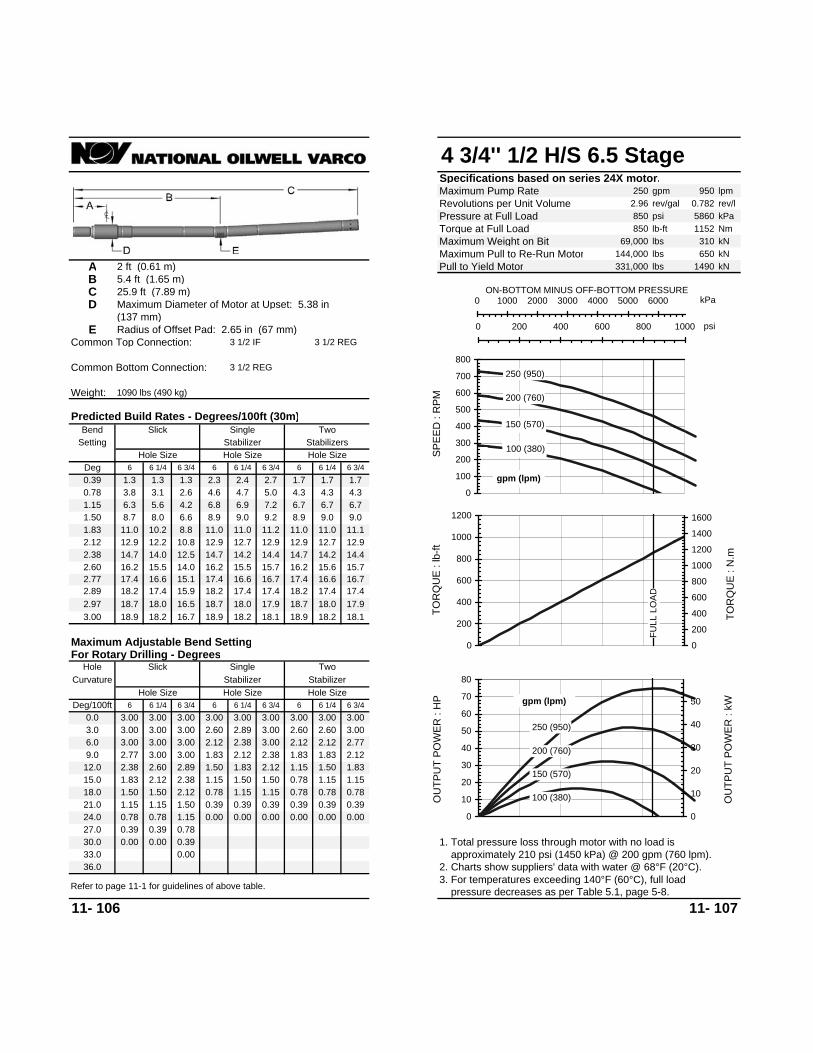
4 3/4'' 1/2 H/S 6.5 StageSpecifications based on series 24X motor.Maximum Pump Rate 250 gpm 950 lpmRevolutions per Unit Volume 2.96 rev/gal 0.782 rev/lPressure at Full Load 850 psi 5860 kPaTorque at Full Load 850 lb-ft 1152 NmMaximum Weight on Bit 69,000 lbs 310 kNMaximum Pull to Re-Run Motor 144,000 lbs 650 kN
A 2 ft (0.61 m) Pull to Yield Motor 331,000 lbs 1490 kNB 5.4 ft (1.65 m)C 25.9 ft (7.89 m)D Maximum Diameter of Motor at Upset: 5.38 in
(137 mm)E Radius of Offset Pad: 2.65 in (67 mm)
Common Top Connection: 3 1/2 IF 3 1/2 REG
Common Bottom Connection: 3 1/2 REG
Weight: 1090 lbs (490 kg)
11- 106 11- 107
Predicted Build Rates - Degrees/100ft (30m)
Setting Stabilizer StabilizersBend
Hole SizeDeg 6 6 1/4 6 3/4
Hole Size Hole Size6 6 1/4 6 3/4 6
For Rotary Drilling - DegreesHole Slick
6 6 1/4 6 3/4Hole Size
Deg/100ft 6 6 1/4 6 3/40.0 3.00 3.00 3.00
Slick Single
33.030.0 0.00 0.00 0.3927.0 0.39 0.39 0.78
Two
6 1/4 6 3/40.39 1.3 1.3 1.3 2.3 2.4 2.7 1.7 1.7 1.70.78 3.8 3.1 2.6 4.6 4.7 5.0 4.3 4.3 4.31.15 6.3 5.6 4.2 6.8 6.9 7.2 6.7 6.7 6.71.50 8.7 8.0 6.6 8.9 9.0 9.2 8.9 9.0 9.01.83 11.0 10.2 8.8 11.0 11.0 11.2 11.0 11.0 11.12.12 12.9 12.2 10.8 12.9 12.7 12.9 12.9 12.7 12.92.38 14.7 14.0 12.5 14.7 14.2 14.4 14.7 14.2 14.42.60 16.2 15.5 14.0 16.2 15.5 15.7 16.2 15.6 15.72.77 17.4 16.6 15.1 17.4 16.6 16.7 17.4 16.6 16.72.89 18.2 17.4 15.9 18.2 17.4 17.4 18.2 17.4 17.42.97 18.7 18.0 16.5 18.7 18.0 17.9 18.7 18.0 17.93.00 18.9 18.2 16.7 18.9 18.2 18.1 18.2
3.00 2.12
Maximum Adjustable Bend Setting
Single Two
3.003.00 3.00
18.118.9
Curvature Stabilizer Stabilizer
3.00 3.00 3.00
Hole Size Hole Size6 6 1/4 6 3/4
3.0 3.00 3.00 3.00
9.0 2.77 3.00 3.00 2.38 1.832.60 2.89 1.50 1.83
1.83 2.122.12 1.1512.0 2.38
15.0 1.83 2.12 2.38 1.15 1.50
2.60 2.892.12 2.38
3.00 2.60 2.60 3.006.0 3.00 3.00 3.00 2.12 2.77
1.50 1.831.83 2.12
1.50 0.78 1.15 1.1518.0 1.50 1.50 2.12 0.780.78 1.15 1.15 0.78
0.00 0.00
0.002. Charts show suppliers' data with water @ 68°F (20°C). approximately 210 psi (1450 kPa) @ 200 gpm (760 lpm).1. Total pressure loss through motor with no load is
0.00 0.00 0.00 0.000.39
24.0 0.78 0.78 1.15
36.0
0.39
3. For temperatures exceeding 140°F (60°C), full load pressure decreases as per Table 5.1, page 5-8.Refer to page 11-1 for guidelines of above table.
21.0 1.15 0.39 0.39 0.39 0.391.15 1.500.78
100 (380)
150 (570)
200 (760)
250 (950)
0
100
200
300
400
500
600
700
800
SPEE
D :
RPM
gpm (lpm)
kPa0 1000 2000 3000 4000 5000 6000ON-BOTTOM MINUS OFF-BOTTOM PRESSURE
psi0 200 400 600 800 1000
FULL
LO
AD
0
200
400
600
800
1000
1200
TOR
QU
E : l
b-ft
0
200
400
600
800
1000
1200
1400
1600
TOR
QU
E : N
.m
100 (380)
150 (570)
200 (760)
250 (950)
0
10
20
30
40
50
60
70
80
OU
TPU
T PO
WER
: H
P
0
10
20
30
40
50
OU
TPU
T PO
WER
: kWgpm (lpm)

4 3/4'' 2/3 M/L 8.0 StageSpecifications based on series 24X motor.Maximum Pump Rate 265 gpm 1000 lpmRevolutions per Unit Volume 1.98 rev/gal 0.523 rev/lPressure at Full Load 1,040 psi 7170 kPaTorque at Full Load 1,300 lb-ft 1762 NmMaximum Weight on Bit 69,000 lbs 310 kNMaximum Pull to Re-Run Motor 144,000 lbs 650 kN
A 2 ft (0.61 m) Pull to Yield Motor 331,000 lbs 1490 kNB 5.4 ft (1.65 m)C 29.66 ft (9.04 m)D Maximum Diameter of Motor at Upset: 5.38 in
(137 mm)E Radius of Offset Pad: 2.65 in (67 mm)
Common Top Connection: 3 1/2 IF 3 1/2 REG
Common Bottom Connection: 3 1/2 REG
Weight: 1250 lbs (570 kg)
11- 108 11- 109
3. For temperatures exceeding 140°F (60°C), full load pressure decreases as per Table 5.1, page 5-8.Refer to page 11-1 for guidelines of above table.
Predicted Build Rates - Degrees/100ft (30m)
Setting StabilizerHole Size Hole Size
Slick Single TwoBend
Hole SizeDeg 6 6 1/4 6 3/4 6 6 1/4 6 3/4 6
For Rotary Drilling - DegreesHole Slick
6 6 1/4 6 3/4Hole Size
Deg/100ft 6 6 1/4 6 3/40.0 3.00 3.00 3.00
33.030.0 0.00 0.0027.0 0.00 0.39 0.78
6 1/4 6 3/4
Stabilizers
0.39 1.2 1.2 1.2 2.0 2.1 2.3 1.5 1.5 1.60.78 3.3 2.7 2.3 4.1 4.2 4.4 3.8 3.8 3.81.15 5.6 5.0 3.7 6.1 6.2 6.4 6.0 6.0 6.01.50 7.7 7.1 5.8 8.0 8.1 8.2 8.0 8.1 8.11.83 9.7 9.1 7.8 9.7 9.8 10.0 9.8 9.8 10.02.12 11.5 10.8 9.6 11.5 11.4 11.6 11.5 11.4 11.62.38 13.1 12.4 11.1 13.1 12.8 12.9 13.1 12.8 12.92.60 14.4 13.7 12.4 14.4 14.0 14.1 14.4 14.0 14.12.77 15.4 14.7 13.4 15.4 14.7 15.0 15.4 14.9 15.02.89 16.1 15.5 14.2 16.1 15.5 15.7 16.1 15.6 15.7
16.6 16.02.97 16.6 16.0 14.6 16.1 16.6 16.0 16.116.3 16.13.00 16.8 16.1 14.8
3.00 2.38
Maximum Adjustable Bend Setting
Single Two
3.003.00 3.00
16.316.816.8 16.1
Curvature Stabilizer Stabilizer
3.00 3.00 3.00
Hole Size Hole Size6 6 1/4 6 3/4
3.0 3.00 3.00 3.00
9.0 3.00 3.00 3.00 2.60 1.832.77 3.00 1.50 1.83
1.83 2.122.12 1.5012.0 2.60
15.0 2.12 2.12 2.60 1.15 1.50
3.00 3.002.38 2.60
3.00 2.77 3.00 3.006.0 3.00 3.00 3.00 2.38 3.00
1.83 1.831.83 2.38
1.50 0.78 1.15 1.1518.0 1.50 1.83 2.12 0.78 0.78 0.78 0.78 0.78 0.78
2. Charts show suppliers' data with water @ 68°F (20°C). approximately 230 psi (1580 kPa) @ 200 gpm (760 lpm).1. Total pressure loss through motor with no load is
0.00 0.00 0.0021.0 1.15 1.15 1.50 0.39 0.39 0.39 0.39 0.3924.0 0.78 0.78 1.15
36.0
0.39
100 (380)
150 (570)
200 (760)
265 (1000)
0
100
200
300
400
500
600
SPEE
D :
RPM
gpm (lpm)
kPa0 2000 4000 6000 8000ON-BOTTOM MINUS OFF-BOTTOM PRESSURE
psi0 200 400 600 800 1000 1200
FULL
LO
AD
0
200
400
600
800
1000
1200
1400
1600
TOR
QU
E : l
b-ft
0
500
1000
1500
2000
TOR
QU
E : N
.m
100 (380)
150 (570)
200 (760)
265 (1000)
0102030405060708090
100110
OU
TPU
T PO
WER
: H
P
0
10
20
30
40
50
60
70
80
OU
TPU
T PO
WER
: kWgpm (lpm)
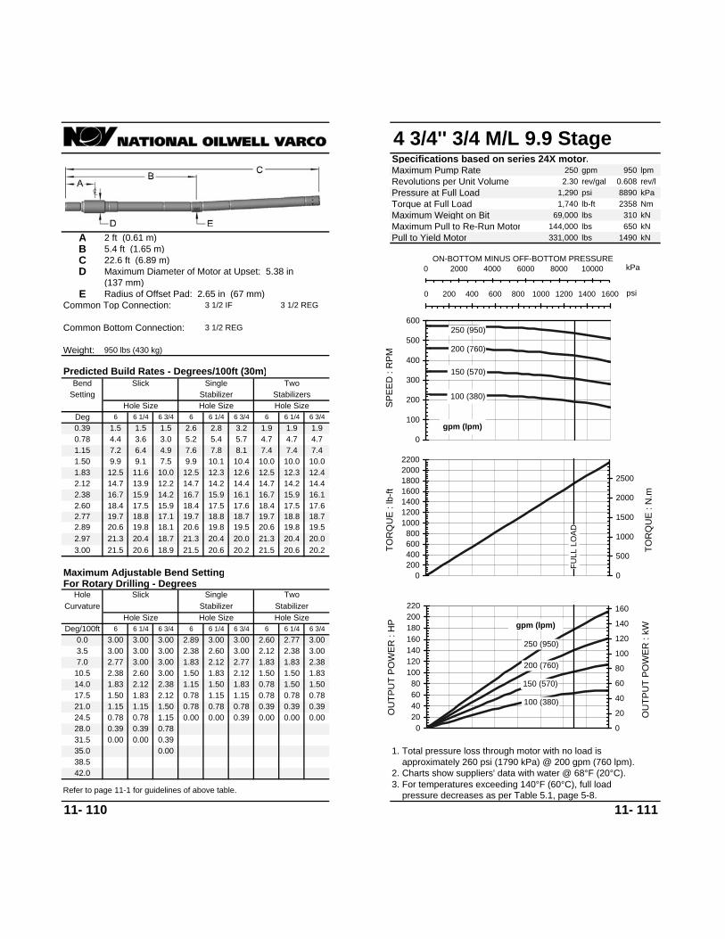
4 3/4'' 3/4 M/L 9.9 StageSpecifications based on series 24X motor.Maximum Pump Rate 250 gpm 950 lpmRevolutions per Unit Volume 2.30 rev/gal 0.608 rev/lPressure at Full Load 1,290 psi 8890 kPaTorque at Full Load 1,740 lb-ft 2358 NmMaximum Weight on Bit 69,000 lbs 310 kNMaximum Pull to Re-Run Motor 144,000 lbs 650 kN
A 2 ft (0.61 m) Pull to Yield Motor 331,000 lbs 1490 kNB 5.4 ft (1.65 m)C 22.6 ft (6.89 m)D Maximum Diameter of Motor at Upset: 5.38 in
(137 mm)E Radius of Offset Pad: 2.65 in (67 mm)
Common Top Connection: 3 1/2 IF 3 1/2 REG
Common Bottom Connection: 3 1/2 REG
Weight: 950 lbs (430 kg)
11- 110 11- 111
Predicted Build Rates - Degrees/100ft (30m)
Setting Stabilizer StabilizersBend
Hole SizeDeg 6 6 1/4 6 3/4
Hole Size Hole Size6 6 1/4 6 3/4 6
For Rotary Drilling - DegreesHole Slick
6 6 1/4 6 3/4Hole Size
Deg/100ft 6 6 1/4 6 3/40.0 3.00 3.00 3.00
Slick Single
38.535.0 0.0031.5 0.00 0.00 0.39
Two
6 1/4 6 3/40.39 1.5 1.5 1.5 2.6 2.8 3.2 1.9 1.9 1.90.78 4.4 3.6 3.0 5.2 5.4 5.7 4.7 4.7 4.71.15 7.2 6.4 4.9 7.6 7.8 8.1 7.4 7.4 7.41.50 9.9 9.1 7.5 9.9 10.1 10.4 10.0 10.0 10.01.83 12.5 11.6 10.0 12.5 12.3 12.6 12.5 12.3 12.42.12 14.7 13.9 12.2 14.7 14.2 14.4 14.7 14.2 14.42.38 16.7 15.9 14.2 16.7 15.9 16.1 16.7 15.9 16.12.60 18.4 17.5 15.9 18.4 17.5 17.6 18.4 17.5 17.62.77 19.7 18.8 17.1 19.7 18.8 18.7 19.7 18.8 18.72.89 20.6 19.8 18.1 20.6 19.8 19.5 20.6 19.8 19.52.97 21.3 20.4 18.7 21.3 20.4 20.0 21.3 20.4 20.03.00 21.5 20.6 18.9 21.5 20.6 20.2 20.6
2.77 1.83
Maximum Adjustable Bend Setting
Single Two
3.002.89 3.00
20.221.5
Curvature Stabilizer Stabilizer
2.60 2.77 3.00
Hole Size Hole Size6 6 1/4 6 3/4
3.5 3.00 3.00 3.00
10.5 2.38 2.60 3.00 2.12 1.502.12 2.38 1.15 1.50
1.50 1.831.83 0.7814.0 1.83
17.5 1.50 1.83 2.12 0.78 1.15
2.38 2.601.83 2.12
3.00 2.12 2.38 3.007.0 2.77 3.00 3.00 1.83 2.38
1.50 1.501.50 1.83
1.15 0.78 0.78 0.7821.0 1.15 1.15 1.50 0.390.78 0.78 0.78 0.39
2. Charts show suppliers' data with water @ 68°F (20°C). approximately 260 psi (1790 kPa) @ 200 gpm (760 lpm).1. Total pressure loss through motor with no load is
0.0028.0 0.39 0.39 0.78
42.0
0.00
3. For temperatures exceeding 140°F (60°C), full load pressure decreases as per Table 5.1, page 5-8.Refer to page 11-1 for guidelines of above table.
24.5 0.78 0.00 0.00 0.39 0.000.78 1.150.39
100 (380)
150 (570)
200 (760)
250 (950)
0
100
200
300
400
500
600
SPEE
D :
RPM
gpm (lpm)
kPa0 2000 4000 6000 8000 10000ON-BOTTOM MINUS OFF-BOTTOM PRESSURE
psi0 200 400 600 800 1000 1200 1400 1600
FULL
LO
AD
0200400600800
1000120014001600180020002200
TOR
QU
E : l
b-ft
0
500
1000
1500
2000
2500
TOR
QU
E : N
.m
100 (380)
150 (570)
200 (760)
250 (950)
020406080
100120140160180200220
OU
TPU
T PO
WER
: H
P
0
20
40
60
80
100
120
140
160
OU
TPU
T PO
WER
: kW
gpm (lpm)

4 3/4'' 4/5 M/L 3.5 StageSpecifications based on series 24X motor.Maximum Pump Rate 250 gpm 950 lpmRevolutions per Unit Volume 1.08 rev/gal 0.285 rev/lPressure at Full Load 460 psi 3170 kPaTorque at Full Load 1,210 lb-ft 1640 NmMaximum Weight on Bit 69,000 lbs 310 kNMaximum Pull to Re-Run Motor 144,000 lbs 650 kN
A 2 ft (0.61 m) Pull to Yield Motor 331,000 lbs 1490 kNB 5.4 ft (1.65 m)C 18 ft (5.49 m)D Maximum Diameter of Motor at Upset: 5.38 in
(137 mm)E Radius of Offset Pad: 2.65 in (67 mm)
Common Top Connection: 3 1/2 IF 3 1/2 REG
Common Bottom Connection: 3 1/2 REG
Weight: 760 lbs (340 kg)
11- 112 11- 113
0.390.3928.0 0.39 0.78 1.15
42.0
0.39 0.39 0.78 0.3924.5 0.78 1.15 1.500.00 0.00 0.39 0.00
2. Charts show suppliers' data with water @ 68°F (20°C). approximately 150 psi (1030 kPa) @ 200 gpm (760 lpm).1. Total pressure loss through motor with no load is
0.78
0.00 0.00
0.780.78 1.15 1.15 0.3921.0 1.15 1.50 1.831.50 0.78 1.15 1.15
1.83 2.38
1.15 1.501.50 1.83
7.0 2.60 2.77 3.003.00 1.83 2.12 2.772.12 2.38
1.83 2.12
1.83 2.12 0.78 1.5014.0 1.8317.5 1.50
2.38 1.152.12 2.38 1.15 1.50
1.50 1.831.83 0.78
10.5 2.12 2.38 2.89
3.5 2.89 3.00 3.00
Stabilizer Stabilizer
2.38 2.38 2.77
Hole Size Hole Size6 6 1/4 6 3/4
Curvature
23.926.626.6 25.2
2.77 1.50
Maximum Adjustable Bend Setting
Single Two
3.002.60 2.77
23.9 25.23.00 26.3 25.2 23.023.7 26.3 24.9 23.72.97 26.0 24.9 22.7
25.4 24.1 23.126.3 24.9
24.2 23.0 22.22.89 25.2 24.1 22.0 25.4 24.1 23.1
22.5 21.4 20.92.77 24.1 23.0 20.9 24.2 23.0 22.2
20.5 19.4 19.22.60 22.5 21.4 19.4 22.5 21.4 20.9
18.0 17.0 17.02.38 20.5 19.4 17.3 20.5 19.4 19.2
15.3 14.5 14.52.12 18.0 17.0 15.0 18.0 17.0 17.2
12.1 11.7 11.71.83 15.3 14.3 12.3 15.3 14.3 15.0
8.7 8.7 8.71.50 12.2 11.2 9.3 12.2 12.1 12.5
5.5 5.5 5.51.15 9.0 8.0 6.1 9.0 9.4 9.9
2.1 2.1 2.20.78 5.5 4.5 3.6 6.3 6.6 7.1
6 1/4 6 3/4
Stabilizers
0.39 1.8 1.8 2.1 3.3 3.6 4.1
31.5 0.00 0.39 0.78
38.535.0 0.00 0.00 0.39
0.00
0.00
0.0 3.00 3.00 3.006 6 1/4 6 3/4
Hole SizeDeg/100ft 6 6 1/4 6 3/4
For Rotary Drilling - DegreesHole Slick
6 6 1/4 6 3/4 6Deg 6 6 1/4 6 3/4
Bend
Hole Size Hole Size Hole Size
Slick Single Two
3. For temperatures exceeding 140°F (60°C), full load pressure decreases as per Table 5.1, page 5-8.Refer to page 11-1 for guidelines of above table.
Predicted Build Rates - Degrees/100ft (30m)
Setting Stabilizer 100 (380)
150 (570)
200 (760)
250 (950)
0
50
100
150
200
250
300
SPEE
D :
RPM
gpm (lpm)
kPa0 1000 2000 3000 4000 5000ON-BOTTOM MINUS OFF-BOTTOM PRESSURE
psi0 200 400 600 800
FULL
LO
AD
0
500
1000
1500
2000
2500
TOR
QU
E : l
b-ft
0
500
1000
1500
2000
2500
3000
TOR
QU
E : N
.m
100 (380)
150 (570)
200 (760)
250 (950)
0
10
20
30
40
50
60
70
OU
TPU
T PO
WER
: H
P
0
10
20
30
40
50
OU
TPU
T PO
WER
: kW
gpm (lpm)

4 3/4'' 4/5 M/L 6.0 StageSpecifications based on series 24X motor.Maximum Pump Rate 250 gpm 950 lpmRevolutions per Unit Volume 1.08 rev/gal 0.285 rev/lPressure at Full Load 780 psi 5370 kPaTorque at Full Load 2,080 lb-ft 2818 NmMaximum Weight on Bit 69,000 lbs 310 kNMaximum Pull to Re-Run Motor 144,000 lbs 650 kN
A 2 ft (0.61 m) Pull to Yield Motor 331,000 lbs 1490 kNB 5.4 ft (1.65 m)C 25.1 ft (7.65 m)D Maximum Diameter of Motor at Upset: 5.38 in
(137 mm)E Radius of Offset Pad: 2.65 in (67 mm)
Common Top Connection: 3 1/2 IF 3 1/2 REG
Common Bottom Connection: 3 1/2 REG
Weight: 1060 lbs (480 kg)
11- 114 11- 115
3. For temperatures exceeding 140°F (60°C), full load pressure decreases as per Table 5.1, page 5-8.Refer to page 11-1 for guidelines of above table.
Predicted Build Rates - Degrees/100ft (30m)
Setting StabilizerHole Size Hole Size
Slick Single TwoBend
Hole SizeDeg 6 6 1/4 6 3/4 6 6 1/4 6 3/4 6
For Rotary Drilling - DegreesHole Slick
6 6 1/4 6 3/4Hole Size
Deg/100ft 6 6 1/4 6 3/40.0 3.00 3.00 3.00
33.030.0 0.00 0.00 0.39
0.00
27.0 0.39 0.39 0.78
6 1/4 6 3/4
Stabilizers
0.39 1.4 1.4 1.4 2.5 2.6 2.9 1.8 1.8 1.80.78 4.1 3.4 2.8 4.9 5.1 5.4 4.5 4.5 4.51.15 6.8 6.1 4.6 7.3 7.4 7.7 7.1 7.1 7.11.50 9.4 8.6 7.1 9.4 9.6 9.9 9.5 9.5 9.51.83 11.8 11.0 9.5 11.8 11.7 12.0 11.8 11.7 11.82.12 13.9 13.1 11.6 13.9 13.6 13.8 13.9 13.6 13.82.38 15.8 15.0 13.5 15.8 15.0 15.4 15.8 15.2 15.42.60 17.5 16.6 15.1 17.5 16.6 16.8 17.5 16.6 16.82.77 18.7 17.9 16.3 18.7 17.9 17.8 18.7 17.9 17.82.89 19.6 18.8 17.1 19.6 18.8 18.6 19.6 18.8 18.6
20.2 19.32.97 20.2 19.3 17.7 19.1 20.2 19.3 19.119.3 19.63.00 20.4 19.6 17.9
3.00 2.12
Maximum Adjustable Bend Setting
Single Two
3.003.00 3.00
19.320.420.4 19.6
Curvature Stabilizer Stabilizer
2.77 3.00 3.00
Hole Size Hole Size6 6 1/4 6 3/4
3.0 3.00 3.00 3.00
2.12 1.159.0 2.60 2.89 3.00
2.38 2.77 1.50 1.8312.0 2.1215.0 1.83 2.12 2.38 1.15 1.50
2.60 2.772.12 2.38
3.00 2.38 2.60 3.00
1.83 2.126.0 3.00 3.00 3.00
2.38 1.501.83 1.83
18.0 1.50 1.50 2.12 0.78 1.15 1.15 0.78 0.78
0.00 0.00
0.781.15 1.15
2.12 2.60
1.50 0.781.50 1.83
2. Charts show suppliers' data with water @ 68°F (20°C). approximately 150 psi (1030 kPa) @ 200 gpm (760 lpm).1. Total pressure loss through motor with no load is
0.00 0.00 0.39 0.0021.0 1.15 1.15 1.50 0.39 0.78 0.78 0.39 0.3924.0 0.78 0.78 1.15
36.0
0.39
100 (380)
150 (570)
200 (760)
250 (950)
0
50
100
150
200
250
300
SPEE
D :
RPM
gpm (lpm)
kPa0 1000 2000 3000 4000 5000 6000ON-BOTTOM MINUS OFF-BOTTOM PRESSURE
psi0 200 400 600 800 1000
FULL
LO
AD
0
500
1000
1500
2000
2500
3000
TOR
QU
E : l
b-ft
0
500
1000
1500
2000
2500
3000
3500
4000
TOR
QU
E : N
.m
100 (380)
150 (570)
200 (760)
250 (950)
0
20
40
60
80
100
120
OU
TPU
T PO
WER
: H
P
0
10
20
30
40
50
60
70
80
OU
TPU
T PO
WER
: kW
gpm (lpm)

4 3/4'' 4/5 M/L 6.3 StageSpecifications based on series 24X motor.Maximum Pump Rate 250 gpm 950 lpmRevolutions per Unit Volume 1.08 rev/gal 0.285 rev/lPressure at Full Load 820 psi 5650 kPaTorque at Full Load 2,180 lb-ft 2954 NmMaximum Weight on Bit 69,000 lbs 310 kNMaximum Pull to Re-Run Motor 144,000 lbs 650 kN
A 2 ft (0.61 m) Pull to Yield Motor 331,000 lbs 1490 kNB 5.4 ft (1.65 m)C 25.66 ft (7.82 m)D Maximum Diameter of Motor at Upset: 5.38 in
(137 mm)E Radius of Offset Pad: 2.65 in (67 mm)
Common Top Connection: 3 1/2 IF 3 1/2 REG
Common Bottom Connection: 3 1/2 REG
Weight: 1080 lbs (490 kg)
11- 116 11- 117
21.0 1.15 0.39 0.39 0.39 0.391.15 1.500.78
3. For temperatures exceeding 140°F (60°C), full load pressure decreases as per Table 5.1, page 5-8.Refer to page 11-1 for guidelines of above table.
0.390.3924.0 0.78 0.78 1.15
36.0
0.00 0.00 0.00 0.00
2. Charts show suppliers' data with water @ 68°F (20°C). approximately 150 psi (1030 kPa) @ 200 gpm (760 lpm).1. Total pressure loss through motor with no load is
0.00
0.00 0.00
0.780.78 1.15 1.15 0.7818.0 1.50 1.50 2.121.50 0.78 1.15 1.15
2.12 2.77
1.50 1.831.83 2.12
6.0 3.00 3.00 3.003.00 2.60 2.60 3.002.60 2.89
2.12 2.38
2.12 2.38 1.15 1.5012.0 2.3815.0 1.83
2.38 1.502.60 2.89 1.50 1.83
1.83 2.122.12 1.15
9.0 2.77 3.00 3.00
3.0 3.00 3.00 3.00
Stabilizer Stabilizer
3.00 3.00 3.00
Hole Size Hole Size6 6 1/4 6 3/4
Curvature
18.219.1
3.00 2.12
Maximum Adjustable Bend Setting
Single Two
3.003.00 3.00
18.2 18.13.00 19.1 18.4 16.8 19.1 18.4 18.2 18.4
17.6 17.62.97 18.9 18.2 16.6 18.9 18.2 18.1 18.9
16.8 16.92.89 18.4 17.6 16.1 18.4 17.6 17.6 18.4
15.6 15.92.77 17.5 16.8 15.3 17.5 16.8 16.9 17.5
14.4 14.62.60 16.4 15.6 14.1 16.4 15.6 15.9 16.4
12.8 13.02.38 14.9 14.1 12.6 14.9 14.4 14.6 14.9
11.1 11.22.12 13.1 12.3 10.9 13.1 12.8 13.0 13.1
9.0 9.01.83 11.1 10.3 8.9 11.1 11.1 11.3 11.1
6.7 6.71.50 8.8 8.1 6.7 9.0 9.1 9.3 9.0
4.3 4.31.15 6.4 5.7 4.3 6.9 7.0 7.2 6.7
1.7 1.70.78 3.8 3.1 2.7 4.6 4.8 5.0 4.3
2.3 2.4 2.7 1.70.39 1.4 1.3 1.3
Two
6 1/4 6 3/4
27.0 0.39 0.39 0.78
33.030.0 0.00 0.00 0.39
Slick Single
0.0 3.00 3.00 3.006 6 1/4 6 3/4
Hole SizeDeg/100ft 6 6 1/4 6 3/4
For Rotary Drilling - DegreesHole Slick
Hole Size Hole Size6 6 1/4 6 3/4 6
Hole SizeDeg 6 6 1/4 6 3/4
Predicted Build Rates - Degrees/100ft (30m)
Setting Stabilizer StabilizersBend
100 (380)
150 (570)
200 (760)
250 (950)
0
50
100
150
200
250
300
SPEE
D :
RPM
gpm (lpm)
kPa0 2000 4000 6000 8000ON-BOTTOM MINUS OFF-BOTTOM PRESSURE
psi0 200 400 600 800 1000 1200
FULL
LO
AD
0
500
1000
1500
2000
2500
3000
3500
TOR
QU
E : l
b-ft
050010001500200025003000350040004500
TOR
QU
E : N
.m
100 (380)
150 (570)
200 (760)
250 (950)
0
20
40
60
80
100
120
OU
TPU
T PO
WER
: H
P
0
10
20
30
40
50
60
70
80
OU
TPU
T PO
WER
: kW
gpm (lpm)

4 3/4'' 5/6 M/L 3.0 StageSpecifications based on series 24X motor.Maximum Pump Rate 250 gpm 950 lpmRevolutions per Unit Volume 1.12 rev/gal 0.296 rev/lPressure at Full Load 390 psi 2690 kPaTorque at Full Load 940 lb-ft 1274 NmMaximum Weight on Bit 69,000 lbs 310 kNMaximum Pull to Re-Run Motor 144,000 lbs 650 kN
A 2 ft (0.61 m) Pull to Yield Motor 331,000 lbs 1490 kNB 5.4 ft (1.65 m)C 16 ft (4.88 m)D Maximum Diameter of Motor at Upset: 5.38 in
(137 mm)E Radius of Offset Pad: 2.65 in (67 mm)
Common Top Connection: 3 1/2 IF 3 1/2 REG
Common Bottom Connection: 3 1/2 REG
Weight: 670 lbs (310 kg)
11- 118 11- 119
28.0 0.78 0.00 0.39 0.39 0.000.78 1.150.39
3. For temperatures exceeding 140°F (60°C), full load pressure decreases as per Table 5.1, page 5-8.Refer to page 11-1 for guidelines of above table.
0.000.0032.0 0.39 0.39 1.15
48.0
0.00
2. Charts show suppliers' data with water @ 68°F (20°C). approximately 150 psi (1030 kPa) @ 200 gpm (760 lpm).1. Total pressure loss through motor with no load is
0.00
0.390.78 0.78 0.78 0.3924.0 1.15 1.15 1.501.15 0.39 0.78 0.78
1.50 2.12
1.15 1.151.15 1.50
8.0 2.38 2.60 3.003.00 1.83 1.83 2.602.12 2.38
1.83 1.83
1.50 2.12 0.78 1.1516.0 1.8320.0 1.50
2.12 1.151.83 2.38 1.15 1.50
1.50 1.501.50 0.78
12.0 2.12 2.12 2.77
4.0 2.77 3.00 3.00
Stabilizer Stabilizer
2.12 2.38 2.60
Hole Size Hole Size6 6 1/4 6 3/4
Curvature
26.030.0
2.60 1.50
Maximum Adjustable Bend Setting
Single Two
3.002.38 2.60
27.6 25.73.00 29.1 27.9 25.5 30.0 27.9 25.5 27.9
26.8 25.12.97 28.8 27.6 25.2 29.6 27.6 25.2 29.6
25.5 24.12.89 28.0 26.8 24.4 28.6 26.8 24.4 28.6
23.8 22.72.77 26.7 25.5 23.2 27.2 25.5 23.2 27.2
21.5 20.72.60 25.0 23.8 21.4 25.2 23.8 22.7 25.2
18.9 18.32.38 22.7 21.5 19.2 22.7 21.5 20.9 22.7
15.6 15.62.12 20.0 18.9 16.6 20.0 18.9 18.8 20.0
12.5 12.51.83 17.0 15.9 13.7 17.0 15.9 16.5 17.0
9.3 9.31.50 13.6 12.5 10.3 13.6 13.2 13.8 13.3
5.9 5.91.15 10.0 8.9 6.8 10.0 10.3 10.9 9.3
2.4 2.40.78 6.2 5.1 4.0 7.0 7.3 7.9 5.9
3.7 4.1 4.7 2.40.39 2.2 2.0 2.4
Two
6 1/4 6 3/4
36.0 0.00 0.39 0.78
44.040.0 0.00 0.39
Slick Single
0.0 3.00 3.00 3.006 6 1/4 6 3/4
Hole SizeDeg/100ft 6 6 1/4 6 3/4
For Rotary Drilling - DegreesHole Slick
Hole Size Hole Size6 6 1/4 6 3/4 6
Hole SizeDeg 6 6 1/4 6 3/4
Predicted Build Rates - Degrees/100ft (30m)
Setting Stabilizer StabilizersBend
100 (380)
150 (570)
200 (760)
250 (950)
0
50
100
150
200
250
300
SPEE
D :
RPM
gpm (lpm)
kPa0 1000 2000 3000 4000ON-BOTTOM MINUS OFF-BOTTOM PRESSURE
psi0 100 200 300 400 500 600
FULL
LO
AD
0
200
400
600
800
1000
1200
1400
1600
TOR
QU
E : l
b-ft
0
500
1000
1500
2000
TOR
QU
E : N
.m
100 (380)
150 (570)
200 (760)
250 (950)
05
101520253035404550
OU
TPU
T PO
WER
: H
P
0
5
10
15
20
25
30
35
OU
TPU
T PO
WER
: kW
gpm (lpm)

4 3/4'' 5/6 M/L 3.0 StageSpecifications based on series 20 motor.Maximum Pump Rate 250 gpm 950 lpmRevolutions per Unit Volume 1.12 rev/gal 0.296 rev/lPressure at Full Load 390 psi 2690 kPaTorque at Full Load 940 lb-ft 1274 NmMaximum Weight on Bit 50,000 lbs 230 kNMaximum Pull to Re-Run Motor 99,000 lbs 450 kN
A 1.8 ft (0.55 m) Pull to Yield Motor 331,000 lbs 1490 kNB 3.8 ft (1.16 m)C 13.9 ft (4.24 m)D Maximum Diameter of Motor at Upset: 5.38 in
(137 mm)E Radius of Offset Pad: 2.65 in (67 mm)
Common Top Connection: 3 1/2 IF 3 1/2 REG
Common Bottom Connection: 3 1/2 REG
Weight: 590 lbs (270 kg)
Bend Slick Single Two
1.04 8.4 6.8 5.8 10.8 11.2 11.8 10.2 10.2 10.2
2.83 28.8 26.9 23.5 28.8 28.8 29.2 28.8 28.8 29.23.06 31.4 29.5 26.0 31.4 31.1 31.4 31.4 31.1 31.4
3.94 41.3 39.4 35.7 41.3 39.4 40.0 41.3 39.4 40.0
Deg/100ft 6 6 1/4 6 3/4 6 6 1/4 6 3/4 6 6 1/4 6 3/40.0 2.83 3.06 3.76 2.29 2.57 2.83 2.00 2.29 2.29
27.0 0.69 1.04 1.69 0.35 0.35 0.35 0.00 0.00 0.00
54.0
11- 120 11- 121
49.5 0.0045.0 0.3540.5 0.00 0.00 0.6936.0 0.35 0.35 1.04
0.69 0.69 0.35
0.000.69 1.37 0.00 0.00
Curvature Stabilizer StabilizerSingle TwoHole Slick
Maximum Adjustable Bend SettingFor Rotary Drilling - Degrees
39.9 40.44.00 42.0 40.1 36.4 42.0 40.1 40.6 42.0
38.5 39.2
3.98 41.8 39.9 36.2 41.8 39.9 40.4 41.8
40.4 38.5 39.2 40.4
37.03.76 39.3 37.4 33.7 39.3 37.4 38.2 39.3 38.2
35.33.63 37.8 35.9 32.3 37.8 35.9 37.0 37.8 36.7
33.63.46 35.9 34.0 30.4 35.9 34.0 35.3 35.9 35.0
26.7
3.28 33.9 32.0 28.4 33.9 33.2 33.6 33.9 33.2
24.02.57 25.8 24.0 20.6 25.8 26.2 26.7 25.8 26.2
21.22.29 22.6 20.9 17.5 22.6 23.5 24.0 23.2 23.5
17.72.00 19.3 17.6 14.3 20.3 20.6 21.2 20.3 20.6
14.01.69 15.8 14.1 10.8 17.3 17.6 18.2 17.3 17.6
6.2
1.37 12.2 10.5 7.6 14.1 14.4 15.0 14.0 14.0
6 1/4 6 3/4 6 6 1/4
Setting
31.5 0.69
0.6922.5 1.04 1.37 2.00
2. Charts show suppliers' data with water @ 68°F (20°C). approximately 150 psi (1030 kPa) @ 200 gpm (760 lpm).1. Total pressure loss through motor with no load is
0.69 0.690.35 0.35
1.04 1.04 1.04 0.6918.0 1.37 1.69 2.291.69 1.04 1.04 1.04
4.5 2.57 2.83 3.28 2.00 2.001.69 2.00 2.00 1.69
13.5 2.002.57 3.062.00 2.57
9.0 2.29
Hole Size
3.86 40.4 38.5 34.8
1.37 1.37
Hole Size Hole Size
2.29 2.291.69 1.37
2.29 2.00
4.4 5.1 2.4
37.9
7.7 6.22.4
8.41.9
0.69 4.54.0
3.9 3.8 7.3
StabilizersHole Size
6 6 1/4 6 3/4
40.1 40.6
Stabilizer
Deg 6
6.20.35 2.0 2.4
Predicted Build Rates - Degrees/100ft (30m)
3. For temperatures exceeding 140°F (60°C), full load pressure decreases as per Table 5.1, page 5-8.Refer to page 11-1 for guidelines of above table.
Hole Size6 3/4
2.4
Hole Size 100 (380)
150 (570)
200 (760)
250 (950)
0
50
100
150
200
250
300
SPEE
D :
RPM
gpm (lpm)
kPa0 1000 2000 3000 4000ON-BOTTOM MINUS OFF-BOTTOM PRESSURE
psi0 100 200 300 400 500 600
FULL
LO
AD
0
200
400
600
800
1000
1200
1400
1600
TOR
QU
E : l
b-ft
0
500
1000
1500
2000
TOR
QU
E : N
.m
100 (380)
150 (570)
200 (760)
250 (950)
05
101520253035404550
OU
TPU
T PO
WER
: H
P
0
10
20
30
OU
TPU
T PO
WER
: kW
gpm (lpm)
4 Degree Adjustable Housing

4 3/4'' 5/6 M/L 8.3 StageSpecifications based on series 24X motor.Maximum Pump Rate 300 gpm 1140 lpmRevolutions per Unit Volume 1.09 rev/gal 0.288 rev/lPressure at Full Load 1,080 psi 7440 kPaTorque at Full Load 2,890 lb-ft 3916 NmMaximum Weight on Bit 69,000 lbs 310 kNMaximum Pull to Re-Run Motor 144,000 lbs 650 kN
A 2 ft (0.61 m) Pull to Yield Motor 331,000 lbs 1490 kNB 5.4 ft (1.65 m)C 28.6 ft (8.72 m)D Maximum Diameter of Motor at Upset: 5.38 in
(137 mm)E Radius of Offset Pad: 2.65 in (67 mm)
Common Top Connection: 3 1/2 IF 3 1/2 REG
Common Bottom Connection: 3 1/2 REG
Weight: 1200 lbs (550 kg)
11- 122 11- 123
Predicted Build Rates - Degrees/100ft (30m)
Setting Stabilizer StabilizersBend
Hole SizeDeg 6 6 1/4 6 3/4
Hole Size Hole Size6 6 1/4 6 3/4 6
For Rotary Drilling - DegreesHole Slick
6 6 1/4 6 3/4Hole Size
Deg/100ft 6 6 1/4 6 3/40.0 3.00 3.00 3.00
Slick Single
33.030.0 0.00 0.3927.0 0.39 0.39 0.78
Two
6 1/4 6 3/40.39 1.2 1.2 1.2 2.0 2.2 2.4 1.6 1.6 1.60.78 3.4 2.8 2.4 4.2 4.3 4.5 3.9 3.9 3.91.15 5.8 5.1 3.9 6.3 6.4 6.6 6.2 6.2 6.21.50 8.0 7.3 6.0 8.2 8.3 8.5 8.2 8.3 8.31.83 10.0 9.4 8.1 10.0 10.1 10.3 10.0 10.1 10.32.12 11.8 11.2 9.8 11.8 11.7 11.9 11.8 11.7 11.92.38 13.4 12.8 11.4 13.4 13.2 13.3 13.4 13.2 13.32.60 14.8 14.1 12.8 14.8 14.4 14.5 14.8 14.4 14.52.77 15.9 15.2 13.9 15.9 15.2 15.4 15.9 15.3 15.42.89 16.6 15.9 14.6 16.6 15.9 16.1 16.6 15.9 16.12.97 17.1 16.4 15.1 17.1 16.4 16.5 17.1 16.4 16.53.00 17.3 16.6 15.3 17.3 16.6 16.7 16.6
3.00 2.12
Maximum Adjustable Bend Setting
Single Two
3.003.00 3.00
16.717.3
Curvature Stabilizer Stabilizer
3.00 3.00 3.00
Hole Size Hole Size6 6 1/4 6 3/4
3.0 3.00 3.00 3.00
9.0 3.00 3.00 3.00 2.60 1.832.60 3.00 1.50 1.83
1.83 2.122.12 1.5012.0 2.38
15.0 2.12 2.12 2.60 1.15 1.50
2.89 3.002.38 2.60
3.00 2.77 2.89 3.006.0 3.00 3.00 3.00 2.38 2.89
1.83 1.831.83 2.38
1.50 0.78 1.15 1.1518.0 1.50 1.83 2.12 0.780.78 0.78 0.78 0.78
2. Charts show suppliers' data with water @ 68°F (20°C). approximately 200 psi (1380 kPa) @ 250 gpm (950 lpm).1. Total pressure loss through motor with no load is
0.00 0.00 0.000.39
24.0 0.78 0.78 1.15
36.0
0.39
3. For temperatures exceeding 140°F (60°C), full load pressure decreases as per Table 5.1, page 5-8.Refer to page 11-1 for guidelines of above table.
21.0 1.15 0.39 0.39 0.39 0.391.15 1.500.78
150 (570)
200 (760)
250 (950)
300 (1140)
0
50
100
150
200
250
300
350
SPEE
D :
RPM
gpm (lpm)
kPa0 2000 4000 6000 8000ON-BOTTOM MINUS OFF-BOTTOM PRESSURE
psi0 200 400 600 800 1000 1200
FULL
LO
AD
0
500
1000
1500
2000
2500
3000
3500
TOR
QU
E : l
b-ft
050010001500200025003000350040004500
TOR
QU
E : N
.m
150 (570)
200 (760)
250 (950)
300 (1140)
0
50
100
150
200
OU
TPU
T PO
WER
: H
P
0
25
50
75
100
125
OU
TPU
T PO
WER
: kW
gpm (lpm)

4 3/4'' 6/7 M/L 6.0 StageSpecifications based on series 24X motor.Maximum Pump Rate 350 gpm 1320 lpmRevolutions per Unit Volume 0.87 rev/gal 0.230 rev/lPressure at Full Load 780 psi 5370 kPaTorque at Full Load 2,230 lb-ft 3022 NmMaximum Weight on Bit 69,000 lbs 310 kNMaximum Pull to Re-Run Motor 144,000 lbs 650 kN
A 2 ft (0.61 m) Pull to Yield Motor 331,000 lbs 1490 kNB 5.4 ft (1.65 m)C 23.6 ft (7.19 m)D Maximum Diameter of Motor at Upset: 5.38 in
(137 mm)E Radius of Offset Pad: 2.65 in (67 mm)
Common Top Connection: 3 1/2 IF 3 1/2 REG
Common Bottom Connection: 3 1/2 REG
Weight: 990 lbs (450 kg)
11- 124 11- 125
21.0 1.15 0.39 0.78 0.78 0.391.15 1.500.78
3. For temperatures exceeding 140°F (60°C), full load pressure decreases as per Table 5.1, page 5-8.Refer to page 11-1 for guidelines of above table.
0.390.3924.0 0.78 0.78 1.15
0.0036.0
0.00 0.00 0.39 0.00
2. Charts show suppliers' data with water @ 68°F (20°C). approximately 150 psi (1030 kPa) @ 300 gpm (1140 lpm).1. Total pressure loss through motor with no load is
0.00
0.00 0.00
0.780.78 1.15 1.15 0.7818.0 1.50 1.50 2.121.50 0.78 1.15 1.15
2.12 2.60
1.50 1.831.83 2.12
6.0 3.00 3.00 3.003.00 2.38 2.60 3.002.60 2.77
2.12 2.38
2.12 2.38 1.15 1.5012.0 2.1215.0 1.83
2.38 1.502.38 2.77 1.50 1.83
1.83 1.832.12 1.15
9.0 2.60 2.77 3.00
3.0 3.00 3.00 3.00
Stabilizer Stabilizer
2.77 2.89 3.00
Hole Size Hole Size6 6 1/4 6 3/4
Curvature
19.520.7
3.00 1.83
Maximum Adjustable Bend Setting
Single Two
3.003.00 3.00
19.6 19.33.00 20.7 19.8 18.2 20.7 19.8 19.5 19.8
19.0 18.82.97 20.4 19.6 18.0 20.4 19.6 19.3 20.4
18.1 18.12.89 19.8 19.0 17.4 19.8 19.0 18.8 19.8
16.9 17.02.77 19.0 18.1 16.5 19.0 18.1 18.1 19.0
15.4 15.62.60 17.7 16.9 15.3 17.7 16.9 17.0 17.7
13.7 13.92.38 16.1 15.2 13.6 16.1 15.2 15.6 16.1
11.9 12.02.12 14.1 13.3 11.8 14.1 13.7 13.9 14.1
9.7 9.71.83 12.0 11.2 9.6 12.0 11.9 12.1 12.0
7.2 7.21.50 9.5 8.7 7.2 9.5 9.8 10.0 9.6
4.6 4.61.15 6.9 6.2 4.7 7.4 7.5 7.8 7.2
1.8 1.80.78 4.2 3.4 2.9 5.0 5.2 5.5 4.6
2.5 2.7 3.0 1.80.39 1.5 1.4 1.4
Two
6 1/4 6 3/4
27.0 0.39 0.39 0.78
33.030.0 0.00 0.00 0.39
0.00
Slick Single
0.0 3.00 3.00 3.006 6 1/4 6 3/4
Hole SizeDeg/100ft 6 6 1/4 6 3/4
For Rotary Drilling - DegreesHole Slick
Hole Size Hole Size6 6 1/4 6 3/4 6
Hole SizeDeg 6 6 1/4 6 3/4
Predicted Build Rates - Degrees/100ft (30m)
Setting Stabilizer StabilizersBend 200 (760)
250 (950)
300 (1140)
350 (1320)
0
50
100
150
200
250
300
350
SPEE
D :
RPM
gpm (lpm)
kPa0 2000 4000 6000 8000ON-BOTTOM MINUS OFF-BOTTOM PRESSURE
psi0 200 400 600 800 1000 1200
FULL
LO
AD
0
500
1000
1500
2000
2500
3000
3500
TOR
QU
E : l
b-ft
050010001500200025003000350040004500
TOR
QU
E : N
.m
200 (760)
250 (950)
300 (1140)
350 (1320)
0
20
40
60
80
100
120
140
160
OU
TPU
T PO
WER
: H
P
0
20
40
60
80
100
OU
TPU
T PO
WER
: kW
gpm (lpm)

4 3/4'' 7/8 M/L 2.0 Stage (Air)Specifications based on series 24X motor.Maximum Pump Rate 250 gpm 950 lpmRevolutions per Unit Volume 0.32 rev/gal 0.085 rev/lPressure at Full Load 260 psi 1790 kPaTorque at Full Load 2,150 lb-ft 2913 NmMaximum Weight on Bit 69,000 lbs 310 kNMaximum Pull to Re-Run Motor 144,000 lbs 650 kN
A 2 ft (0.61 m) Pull to Yield Motor 331,000 lbs 1490 kNB 5.4 ft (1.65 m)C 22.5 ft (6.86 m)D Maximum Diameter of Motor at Upset: 5.38 in
(137 mm)E Radius of Offset Pad: 2.65 in (67 mm)
Common Top Connection: 3 1/2 IF 3 1/2 REG
Common Bottom Connection: 3 1/2 REG
Weight: 950 lbs (430 kg)
11- 126 11- 127
Predicted Build Rates - Degrees/100ft (30m)
Setting Stabilizer StabilizersBend
Hole SizeDeg 6 6 1/4 6 3/4
Hole Size Hole Size6 6 1/4 6 3/4 6
For Rotary Drilling - DegreesHole Slick
6 6 1/4 6 3/4Hole Size
Deg/100ft 6 6 1/4 6 3/40.0 3.00 3.00 3.00
Slick Single
0.00
33.030.0 0.00 0.00 0.3927.0 0.39 0.39 0.78
Two
6 1/4 6 3/40.39 1.5 1.5 1.4 2.5 2.7 3.0 1.8 1.8 1.80.78 4.2 3.5 2.9 5.0 5.2 5.5 4.6 4.6 4.61.15 7.0 6.2 4.7 7.4 7.6 7.9 7.2 7.2 7.21.50 9.6 8.8 7.3 9.6 9.8 10.1 9.7 9.7 9.71.83 12.1 11.3 9.7 12.1 11.9 12.2 12.1 11.9 12.02.12 14.2 13.4 11.8 14.2 13.8 14.0 14.2 13.8 14.02.38 16.2 15.3 13.7 16.2 15.3 15.7 16.2 15.5 15.72.60 17.8 17.0 15.4 17.8 17.0 17.1 17.8 17.0 17.12.77 19.1 18.2 16.6 19.1 18.2 18.2 19.1 18.2 18.22.89 20.0 19.1 17.5 20.0 19.1 18.9 20.0 19.1 18.92.97 20.6 19.7 18.1 20.6 19.7 19.4 20.6 19.7 19.43.00 20.8 20.0 18.3 20.8 20.0 19.6 20.0
3.00 1.83
Maximum Adjustable Bend Setting
Single Two
3.002.89 3.00
19.620.8
Curvature Stabilizer Stabilizer
2.77 2.89 3.00
Hole Size Hole Size6 6 1/4 6 3/4
3.0 3.00 3.00 3.00
9.0 2.60 2.77 3.00 2.38 1.502.38 2.77 1.50 1.83
1.83 1.832.12 1.1512.0 2.12
15.0 1.83 2.12 2.38 1.15 1.50
2.60 2.772.12 2.38
3.00 2.38 2.38 3.006.0 3.00 3.00 3.00 2.12 2.60
1.50 1.831.83 2.12
1.50 0.78 1.15 1.1518.0 1.50 1.50 2.12 0.780.78 1.15 1.15 0.78
0.00 0.00
0.002. Charts show suppliers' data with water @ 68°F (20°C). approximately 50 psi (340 kPa) @ 200 gpm (760 lpm).1. Total pressure loss through motor with no load is
0.00 0.00 0.39 0.000.39
24.0 0.78 0.78 1.15
0.0036.0
0.39
3. For temperatures exceeding 140°F (60°C), full load pressure decreases as per Table 5.1, page 5-8.Refer to page 11-1 for guidelines of above table.
21.0 1.15 0.39 0.78 0.78 0.391.15 1.500.78
100 (380)
150 (570)
200 (760)
250 (950)
0102030405060708090
SPEE
D :
RPM
gpm (lpm)
kPa0 500 1000 1500 2000 2500ON-BOTTOM MINUS OFF-BOTTOM PRESSURE
0 100 200 300 400
FULL
LO
AD
0
500
1000
1500
2000
2500
3000
3500
TOR
QU
E : l
b-ft
050010001500200025003000350040004500
TOR
QU
E : N
.m
100 (380)
150 (570)
200 (760)
250 (950)
0
5
10
15
20
25
30
35
40
45
OU
TPU
T PO
WER
: H
P
0
5
10
15
20
25
30
OU
TPU
T PO
WER
: kW
gpm (lpm)
psi

4 3/4'' 7/8 M/L 2.0 StageSpecifications based on series 20 motor.Maximum Pump Rate 250 gpm 950 lpmRevolutions per Unit Volume 0.32 rev/gal 0.085 rev/lPressure at Full Load 260 psi 1790 kPaTorque at Full Load 940 lb-ft 1274 NmMaximum Weight on Bit 50,000 lbs 230 kNMaximum Pull to Re-Run Motor 99,000 lbs 450 kN
A 1.8 ft (0.55 m) Pull to Yield Motor 331,000 lbs 1490 kNB 3.8 ft (1.16 m)C 20.8 ft (6.34 m)D Maximum Diameter of Motor at Upset: 5.38 in
(137 mm)E Radius of Offset Pad: 2.65 in (67 mm)
Common Top Connection: 3 1/2 IF 3 1/2 REG
Common Bottom Connection: 3 1/2 REG
Weight: 880 lbs (400 kg)
Bend Slick Single Two
1.04 6.2 4.9 4.4 8.1 8.3 8.7 7.9 7.9 7.9
2.83 21.6 20.3 17.7 22.1 22.2 22.5 22.1 22.2 22.53.06 23.6 22.2 19.6 23.9 24.0 24.2 23.9 24.0 24.2
3.94 31.1 29.7 27.1 31.1 30.9 31.0 31.1 30.9 31.0
Deg/100ft 6 6 1/4 6 3/4 6 6 1/4 6 3/4 6 6 1/4 6 3/40.0 3.46 3.63 4.00 2.83 2.83 3.06 2.57 2.57 2.57
21.0 1.04 1.37 1.69 0.35 0.35 0.69 0.35 0.35 0.35
42.0
11- 128 11- 129
Predicted Build Rates - Degrees/100ft (30m)
Hole Size6 3/4
StabilizerSetting
6 1/41.83.4
6 1/4 6 3/4 6Hole Size
Deg 6
31.3 31.4
StabilizersHole Size
6 6 1/4 6 3/41.8
29.5 29.6
1.86.0 4.8
0.35 1.5 1.5 1.50.69 3.1
2.7 2.9
Hole Size
3.86 30.4 29.1 26.4
10.5 2.292.83 3.282.57 2.83
7.0 2.571.69 1.69
Hole Size Hole Size
2.57 2.572.00 2.00
1.69 1.37
3.5 3.06 3.28 3.76
1.37 1.3714.0 2.00 2.00 2.57 1.37 1.37 1.37 1.04 1.04 1.04
0.69 0.69
2. Charts show suppliers' data with water @ 68°F (20°C). approximately 100 psi (690 kPa) @ 200 gpm (760 lpm).1. Total pressure loss through motor with no load is
1.04 1.04 0.69
0.00 0.00
0.6917.5 1.69 1.69 2.29
24.5 0.69
3.0 3.4 5.4 5.6 4.8 4.8
1.37 9.0 7.8 5.8 10.7 10.9 11.2 10.7 10.8 10.81.69 11.8 10.5 8.0 13.2 13.4 13.7 13.2 13.4 13.62.00 14.4 13.2 10.7 15.6 15.8 16.1 15.6 15.8 16.12.29 16.9 15.6 13.1 17.9 18.0 18.3 17.9 18.0 18.32.57 19.3 18.0 15.5 20.1 20.2 20.5 20.1 20.2 20.5
3.28 25.5 24.1 21.5 25.5 25.7 25.9 25.5 25.7 25.93.46 27.0 25.6 23.0 27.0 27.1 27.3 27.0 27.1 27.33.63 28.5 27.1 24.4 28.5 28.5 28.6 28.5 28.5 28.63.76 29.6 28.2 25.5 29.6 29.5 29.6 29.6
30.4 30.2 30.4 30.4 30.2 30.4
3.98 31.5 30.1 27.4 31.5 31.2 31.3 31.5 31.2 31.34.00 31.6 30.3 27.6 31.6 31.3 31.4 31.6
Maximum Adjustable Bend SettingFor Rotary Drilling - Degrees
TwoHole SlickCurvature Stabilizer Stabilizer
Single
2.57 2.29 2.29 2.292.00 2.00 2.29 2.00
1.04 1.37 0.00 0.00 0.00 0.0028.0 0.35 0.69 1.0431.5 0.00 0.35 0.6935.0 0.00 0.35
3. For temperatures exceeding 140°F (60°C), full load pressure decreases as per Table 5.1, page 5-8.Refer to page 11-1 for guidelines of above table.
38.5 0.00
100 (380)
150 (570)
200 (760)
250 (950)
020406080
100120140160180
SPEE
D :
RPM
gpm (lpm)
kPa0 500 1000 1500 2000 2500ON-BOTTOM MINUS OFF-BOTTOM PRESSURE
0 100 200 300 400
FULL
LO
AD
0
250
500
750
1000
1250
1500
TOR
QU
E : l
b-ft
0
250
500
750
1000
1250
1500
1750
2000
TOR
QU
E : N
.m
100 (380)
150 (570)
200 (760)
250 (950)
0
5
10
15
20
25
30
35
40
45
OU
TPU
T PO
WER
: H
P
0
5
10
15
20
25
30
OU
TPU
T PO
WER
: kW
gpm (lpm)
psi
4 Degree Adjustable Housing

4 3/4'' 7/8 M/L 2.2 StageSpecifications based on series 24X motor.Maximum Pump Rate 250 gpm 950 lpmRevolutions per Unit Volume 0.56 rev/gal 0.148 rev/lPressure at Full Load 290 psi 2000 kPaTorque at Full Load 1,340 lb-ft 1816 NmMaximum Weight on Bit 69,000 lbs 310 kNMaximum Pull to Re-Run Motor 144,000 lbs 650 kN
A 2 ft (0.61 m) Pull to Yield Motor 331,000 lbs 1490 kNB 5.4 ft (1.65 m)C 18.5 ft (5.64 m)D Maximum Diameter of Motor at Upset: 5.38 in
(137 mm)E Radius of Offset Pad: 2.65 in (67 mm)
Common Top Connection: 3 1/2 IF 3 1/2 REG
Common Bottom Connection: 3 1/2 REG
Weight: 780 lbs (350 kg)
11- 130 11- 131
0.390.3928.0 0.39 0.78 1.15
42.0
0.39 0.39 0.78 0.3924.5 0.78 1.15 1.500.00 0.00 0.39 0.00
2. Charts show suppliers' data with water @ 68°F (20°C). approximately 150 psi (1030 kPa) @ 200 gpm (760 lpm).1. Total pressure loss through motor with no load is
0.78
0.00 0.00
0.780.78 1.15 1.15 0.3921.0 1.15 1.50 1.831.50 0.78 1.15 1.15
1.83 2.38
1.15 1.501.50 1.83
7.0 2.60 2.77 3.003.00 1.83 2.12 2.772.12 2.38
1.83 2.12
1.83 2.12 0.78 1.5014.0 1.8317.5 1.50
2.38 1.152.12 2.38 1.15 1.50
1.50 1.831.83 0.78
10.5 2.12 2.38 2.89
3.5 2.89 3.00 3.00
Stabilizer Stabilizer
2.38 2.38 2.77
Hole Size Hole Size6 6 1/4 6 3/4
Curvature
23.926.626.6 25.2
2.77 1.50
Maximum Adjustable Bend Setting
Single Two
3.002.60 2.77
23.9 25.23.00 26.3 25.2 23.023.7 26.3 24.9 23.72.97 26.0 24.9 22.7
25.4 24.1 23.126.3 24.9
24.2 23.0 22.22.89 25.2 24.1 22.0 25.4 24.1 23.1
22.5 21.4 20.92.77 24.1 23.0 20.9 24.2 23.0 22.2
20.5 19.4 19.22.60 22.5 21.4 19.4 22.5 21.4 20.9
18.0 17.0 17.02.38 20.5 19.4 17.3 20.5 19.4 19.2
15.3 14.5 14.52.12 18.0 17.0 15.0 18.0 17.0 17.2
12.1 11.7 11.71.83 15.3 14.3 12.3 15.3 14.3 15.0
8.7 8.7 8.71.50 12.2 11.2 9.3 12.2 12.1 12.5
5.5 5.5 5.51.15 9.0 8.0 6.1 9.0 9.4 9.9
2.1 2.1 2.20.78 5.5 4.5 3.6 6.3 6.6 7.1
6 1/4 6 3/4
Stabilizers
0.39 1.8 1.8 2.1 3.3 3.6 4.1
31.5 0.00 0.39 0.78
38.535.0 0.00 0.00 0.39
0.00
0.00
0.0 3.00 3.00 3.006 6 1/4 6 3/4
Hole SizeDeg/100ft 6 6 1/4 6 3/4
For Rotary Drilling - DegreesHole Slick
6 6 1/4 6 3/4 6Deg 6 6 1/4 6 3/4
Bend
Hole Size Hole Size Hole Size
Slick Single Two
3. For temperatures exceeding 140°F (60°C), full load pressure decreases as per Table 5.1, page 5-8.Refer to page 11-1 for guidelines of above table.
Predicted Build Rates - Degrees/100ft (30m)
Setting Stabilizer 100 (380)
150 (570)
200 (760)
250 (950)
0
25
50
75
100
125
150
SPEE
D :
RPM
gpm (lpm)
kPa0 500 1000 1500 2000 2500ON-BOTTOM MINUS OFF-BOTTOM PRESSURE
0 50 100 150 200 250 300 350 400 psi
FULL
LO
AD
0
500
1000
1500
2000
TOR
QU
E : l
b-ft
0
500
1000
1500
2000
2500
TOR
QU
E : N
.m
100 (380)
150 (570)
200 (760)
250 (950)
0
5
10
15
20
25
30
35
40
OU
TPU
T PO
WER
: H
P
0
5
10
15
20
25
OU
TPU
T PO
WER
: kWgpm (lpm)

4 3/4'' 7/8 M/L 2.2 StageSpecifications based on series 20 motor.Maximum Pump Rate 250 gpm 950 lpmRevolutions per Unit Volume 0.56 rev/gal 0.148 rev/lPressure at Full Load 290 psi 2000 kPaTorque at Full Load 1,330 lb-ft 1802 NmMaximum Weight on Bit 50,000 lbs 230 kNMaximum Pull to Re-Run Motor 99,000 lbs 450 kN
A 0.9 ft (0.27 m) Pull to Yield Motor 331,000 lbs 1490 kNB 3.8 ft (1.16 m)C 15.2 ft (4.63 m)D Maximum Diameter of Motor at Upset: 5.38 in
(137 mm)E Radius of Offset Pad: 2.65 in (67 mm)
Common Top Connection: 3 1/2 IF 3 1/2 REG
Common Bottom Connection: 3 1/2 REG
Weight: 640 lbs (290 kg)
Bend Slick Single Two
1.04 7.4 6.0 5.2 9.7 9.9 10.5 9.2 9.2 9.2
2.83 25.7 24.1 21.0 25.7 26.0 26.4 25.7 26.0 26.43.06 28.0 26.4 23.3 28.0 28.1 28.4 28.0 28.1 28.4
3.94 37.0 35.3 32.0 37.0 35.3 36.2 37.0 36.0 36.2
Deg/100ft 6 6 1/4 6 3/4 6 6 1/4 6 3/4 6 6 1/4 6 3/40.0 3.06 3.28 3.76 2.29 2.83 2.83 2.29 2.57 2.57
24.0 1.04 1.37 1.69 0.35 0.35 0.35 0.00 0.00 0.00
48.0
11- 132 11- 133
3. For temperatures exceeding 140°F (60°C), full load pressure decreases as per Table 5.1, page 5-8.Refer to page 11-1 for guidelines of above table.
Predicted Build Rates - Degrees/100ft (30m)
Hole Size6 3/4
StabilizerSetting
6 1/42.12.14.4
6Hole Size
Deg 6 6 1/4 6 3/4
36.5 36.7
StabilizersHole Size
6 6 1/4 6 3/42.1
34.4 34.6
7.4 5.60.35 1.8 2.1 1.80.69 3.9
3.4 3.7
Hole Size
3.86 36.1 34.5 31.2
12.0 2.002.57 3.062.29 2.83
8.0 2.291.37 1.69
Hole Size Hole Size
2.29 2.291.69 1.69
1.69 1.37
4.0 2.57 2.83 3.46
1.37 1.3716.0 1.69 2.00 2.29 1.04 1.04 1.37 1.04 1.04 1.04
0.35 0.35
2. Charts show suppliers' data with water @ 68°F (20°C). approximately 140 psi (960 kPa) @ 200 gpm (760 lpm).1. Total pressure loss through motor with no load is
0.69 0.69 0.35
0.00
0.6920.0 1.37 1.69 2.00
28.0 0.69
3.5 4.2 6.5 6.8 5.6 5.6
1.37 10.8 9.3 6.8 12.6 12.9 13.4 12.6 12.7 12.71.69 14.1 12.6 9.6 15.5 15.8 16.3 15.5 15.8 16.02.00 17.2 15.7 12.7 18.3 18.6 19.0 18.3 18.6 19.02.29 20.2 18.6 15.6 21.0 21.2 21.6 21.0 21.2 21.62.57 23.0 21.4 18.4 23.0 23.7 24.1 23.5 23.7 24.1
3.28 30.3 28.6 25.5 30.3 30.1 30.4 30.3 30.1 30.43.46 32.1 30.4 27.3 32.1 31.7 31.9 32.1 31.7 31.93.63 33.8 32.2 28.9 33.8 33.2 33.5 33.8 33.2 33.53.76 35.1 33.5 30.2 35.1 34.4 34.6 35.1
36.1 35.3 35.5 36.1 35.3 35.5
3.98 37.4 35.7 32.4 37.4 35.7 36.6 37.4 36.4 36.64.00 37.6 35.9 32.6 37.6 35.9 36.7 37.6
Maximum Adjustable Bend SettingFor Rotary Drilling - Degrees
TwoHole SlickCurvature Stabilizer Stabilizer
Single
2.57 2.00 2.00 2.002.00 2.00 2.00 1.69
1.04 1.37 0.00 0.0032.0 0.35 0.69 1.0436.0 0.00 0.35 0.6940.0 0.00 0.3544.0 0.00
100 (380)
150 (570)
200 (760)
250 (950)
0
25
50
75
100
125
150
SPEE
D :
RPM
gpm (lpm)
kPa0 500 1000 1500 2000 2500ON-BOTTOM MINUS OFF-BOTTOM PRESSURE
0 50 100 150 200 250 300 350 400 psi
FULL
LO
AD
0
500
1000
1500
2000
TOR
QU
E : l
b-ft
0
500
1000
1500
2000
2500
TOR
QU
E : N
.m
100 (380)
150 (570)
200 (760)
250 (950)
0
5
10
15
20
25
30
35
40
OU
TPU
T PO
WER
: H
P
0
5
10
15
20
25
OU
TPU
T PO
WER
: kW
gpm (lpm)
4 Degree Adjustable Housing

4 3/4'' 7/8 M/L 3.8 StageSpecifications based on series 24X motor.Maximum Pump Rate 250 gpm 950 lpmRevolutions per Unit Volume 0.56 rev/gal 0.148 rev/lPressure at Full Load 490 psi 3380 kPaTorque at Full Load 2,430 lb-ft 3293 NmMaximum Weight on Bit 69,000 lbs 310 kNMaximum Pull to Re-Run Motor 144,000 lbs 650 kN
A 2 ft (0.61 m) Pull to Yield Motor 331,000 lbs 1490 kNB 5.4 ft (1.65 m)C 23.9 ft (7.28 m)D Maximum Diameter of Motor at Upset: 5.38 in
(137 mm)E Radius of Offset Pad: 2.65 in (67 mm)
Common Top Connection: 3 1/2 IF 3 1/2 REG
Common Bottom Connection: 3 1/2 REG
Weight: 1010 lbs (460 kg)
11- 134 11- 135
21.0 1.15 0.39 0.78 0.78 0.391.15 1.500.78
3. For temperatures exceeding 140°F (60°C), full load pressure decreases as per Table 5.1, page 5-8.Refer to page 11-1 for guidelines of above table.
0.390.3924.0 0.78 0.78 1.15
36.0
0.00 0.00 0.39 0.00
2. Charts show suppliers' data with water @ 68°F (20°C). approximately 210 psi (1450 kPa) @ 220 gpm (830 lpm).1. Total pressure loss through motor with no load is
0.00
0.00 0.00
0.780.78 1.15 1.15 0.7818.0 1.50 1.50 2.121.50 0.78 1.15 1.15
2.12 2.60
1.50 1.831.83 2.12
6.0 3.00 3.00 3.003.00 2.38 2.60 3.002.60 2.77
2.12 2.38
2.12 2.38 1.15 1.5012.0 2.1215.0 1.83
2.38 1.502.38 2.77 1.50 1.83
1.83 1.832.12 1.15
9.0 2.60 2.89 3.00
3.0 3.00 3.00 3.00
Stabilizer Stabilizer
2.77 3.00 3.00
Hole Size Hole Size6 6 1/4 6 3/4
Curvature
19.320.4
3.00 2.12
Maximum Adjustable Bend Setting
Single Two
3.003.00 3.00
19.3 19.13.00 20.4 19.6 17.9 20.4 19.6 19.3 19.6
18.8 18.62.97 20.2 19.3 17.7 20.2 19.3 19.1 20.2
17.9 17.82.89 19.6 18.8 17.1 19.6 18.8 18.6 19.6
16.6 16.82.77 18.7 17.9 16.3 18.7 17.9 17.8 18.7
15.2 15.42.60 17.5 16.6 15.1 17.5 16.6 16.8 17.5
13.6 13.82.38 15.8 15.0 13.5 15.8 15.0 15.4 15.8
11.7 11.82.12 13.9 13.1 11.6 13.9 13.6 13.8 13.9
9.5 9.51.83 11.8 11.0 9.5 11.8 11.7 12.0 11.8
7.1 7.11.50 9.4 8.6 7.1 9.4 9.6 9.9 9.5
4.5 4.51.15 6.8 6.1 4.6 7.3 7.4 7.7 7.1
1.8 1.80.78 4.1 3.4 2.8 4.9 5.1 5.4 4.5
2.5 2.6 2.9 1.80.39 1.4 1.4 1.4
Two
6 1/4 6 3/4
27.0 0.39 0.39 0.78
33.030.0 0.00 0.00 0.39
Slick Single
0.0 3.00 3.00 3.006 6 1/4 6 3/4
Hole SizeDeg/100ft 6 6 1/4 6 3/4
For Rotary Drilling - DegreesHole Slick
Hole Size Hole Size6 6 1/4 6 3/4 6
Hole SizeDeg 6 6 1/4 6 3/4
Predicted Build Rates - Degrees/100ft (30m)
Setting Stabilizer StabilizersBend
160 (610) 190 (720) 220 (830)
250 (950)
0
25
50
75
100
125
150
SPEE
D :
RPM
gpm (lpm)
kPa0 1000 2000 3000 4000ON-BOTTOM MINUS OFF-BOTTOM PRESSURE
0 100 200 300 400 500 600
FULL
LO
AD
0
500
1000
1500
2000
2500
3000
TOR
QU
E : l
b-ft
0
500
1000
1500
2000
2500
3000
3500
4000
TOR
QU
E : N
.m
160 (610)
190 (720)
220 (830)
250 (950)
0
10
20
30
40
50
60
70
OU
TPU
T PO
WER
: H
P
0
10
20
30
40
50
OU
TPU
T PO
WER
: kW
gpm (lpm)
psi

5'' 6/7 M/L 6.0 StageSpecifications based on series 24X motor.Maximum Pump Rate 350 gpm 1320 lpmRevolutions per Unit Volume 0.86 rev/gal 0.227 rev/lPressure at Full Load 780 psi 5370 kPaTorque at Full Load 2,250 lb-ft 3049 NmMaximum Weight on Bit 69,000 lbs 310 kNMaximum Pull to Re-Run Motor 144,000 lbs 650 kN
A 2.1 ft (0.64 m) Pull to Yield Motor 400,000 lbs 1800 kNB 5.4 ft (1.65 m)C 24.92 ft (7.6 m)D Maximum Diameter of Motor at Upset: 5.38 in
(137 mm)E Radius of Offset Pad: 2.78 in (71 mm)
Common Top Connection: 3 1/2 IF 3 1/2 REG
Common Bottom Connection: 3 1/2 REG
Weight: 1160 lbs (530 kg)
11- 136 11- 137
3. For temperatures exceeding 140°F (60°C), full load pressure decreases as per Table 5.1, page 5-8.
Predicted Build Rates - Degrees/100ft (30m)
Setting Stabilizer StabilizersBend
Hole Size
Slick
Deg 6 6 1/4 6 3/4Hole Size Hole Size
6 6 1/4 6 3/4 6
For Rotary Drilling - DegreesHole Slick
6 6 1/4 6 3/4Hole Size
Deg/100ft 6 6 1/4 6 3/40.0 3.00 3.00 3.00
Single
Refer to page 11-1 for guidelines of above table.
27.525.0 0.00 0.00
0.00
22.5 0.00 0.00 0.39
Two
6 1/4 6 3/40.39 2.0 1.4 1.6 2.2 2.4 2.7 1.8 1.8 1.80.78 4.7 4.0 2.7 4.7 4.8 5.1 4.5 4.4 4.41.15 7.4 6.6 5.2 7.4 7.1 7.3 7.4 6.9 6.91.50 9.9 9.1 7.6 9.9 9.1 9.5 9.9 9.2 9.31.83 12.2 11.5 10.0 12.2 11.5 11.5 12.2 11.5 11.52.12 14.3 13.5 12.0 14.3 13.5 13.3 14.3 13.5 13.32.38 16.2 15.4 13.8 16.2 15.4 14.9 16.2 15.4 14.92.60 17.7 16.9 15.4 17.7 16.9 16.2 17.7 16.9 16.22.77 18.9 18.1 16.6 19.1 18.1 17.2 19.1 18.1 17.22.89 19.8 19.0 17.4 20.0 19.0 18.0 20.0 19.0 18.02.97 20.4 19.5 18.0 20.6 19.5 18.5 20.6 19.5 18.53.00 20.6 19.8 18.2 20.9 19.8 18.7 19.8
2.38 1.50
Maximum Adjustable Bend Setting
Single Two
2.892.12 2.38
18.720.9
Curvature Stabilizer Stabilizer
2.12 2.12 2.60
Hole Size Hole Size6 6 1/4 6 3/4
2.5 2.60 2.77 3.00
0.787.5 1.83 2.12 2.38
12.5 1.15
1.83 1.151.83 2.12 0.78 1.15
1.15 1.50
1.50 1.83 0.78 0.78
1.83 2.121.50 1.83
2.60 1.83 1.83 2.38
1.151.15 1.50
5.0 2.38 2.38 2.77
10.0 1.50 1.50
15.0 0.78 1.15 1.50 0.39 0.78 0.78 0.00 0.39 0.390.78 0.78
1.50 2.12
0.781.15 0.39
2. Charts show suppliers' data with water @ 68°F (20°C). approximately 205 psi (1410 kPa) @ 300 gpm (1140 lpm).1. Total pressure loss through motor with no load is
0.00 0.00 0.0017.5 0.78 0.78 1.15 0.00 0.39 0.39 0.00 0.0020.0 0.39 0.39 0.78
30.0
0.00
200 (760)
250 (950)
300 (1140)
350 (1320)
0
50
100
150
200
250
300
350
SPEE
D :
RPM
gpm (lpm)
kPa0 1000 2000 3000 4000 5000 6000ON-BOTTOM MINUS OFF-BOTTOM PRESSURE
psi0 200 400 600 800 1000
FULL
LO
AD
0
500
1000
1500
2000
2500
3000
TOR
QU
E : l
b-ft
0
500
1000
1500
2000
2500
3000
3500
4000
TOR
QU
E : N
.m
200 (760)
250 (950)
300 (1140)
350 (1320)
0
20
40
60
80
100
120
140
160
OU
TPU
T PO
WER
: H
P
0
20
40
60
80
100
OU
TPU
T PO
WER
: kW
gpm (lpm)

5'' 6/7 M/L 7.0 StageSpecifications based on series 24X motor.Maximum Pump Rate 350 gpm 1320 lpmRevolutions per Unit Volume 0.86 rev/gal 0.227 rev/lPressure at Full Load 910 psi 6270 kPaTorque at Full Load 2,620 lb-ft 3550 NmMaximum Weight on Bit 69,000 lbs 310 kNMaximum Pull to Re-Run Motor 144,000 lbs 650 kN
A 2.1 ft (0.64 m) Pull to Yield Motor 400,000 lbs 1800 kNB 5.4 ft (1.65 m)C 27.3 ft (8.32 m)D Maximum Diameter of Motor at Upset: 5.38 in
(137 mm)E Radius of Offset Pad: 2.78 in (71 mm)
Common Top Connection: 3 1/2 IF 3 1/2 REG
Common Bottom Connection: 3 1/2 REG
Weight: 1270 lbs (580 kg)
11- 138 11- 139
3. For temperatures exceeding 140°F (60°C), full load pressure decreases as per Table 5.1, page 5-8.Refer to page 11-1 for guidelines of above table.
Predicted Build Rates - Degrees/100ft (30m)
Setting StabilizerHole Size Hole Size
Slick Single TwoBend
Hole SizeDeg 6 6 1/4 6 3/4 6 6 1/4 6 3/4 6
For Rotary Drilling - DegreesHole Slick
6 6 1/4 6 3/4Hole Size
Deg/100ft 6 6 1/4 6 3/40.0 3.00 3.00 3.00
27.525.0 0.0022.5 0.00 0.00 0.39
6 1/4 6 3/4
Stabilizers
0.39 1.8 1.3 1.4 2.0 2.2 2.4 1.7 1.7 1.70.78 4.4 3.7 2.5 4.4 4.4 4.7 4.2 4.1 4.11.15 6.8 6.1 4.8 6.8 6.6 6.8 6.8 6.5 6.51.50 9.1 8.4 7.1 9.1 8.6 8.8 9.1 8.6 8.71.83 11.3 10.6 9.2 11.3 10.6 10.7 11.3 10.6 10.72.12 13.2 12.5 11.1 13.2 12.5 12.4 13.2 12.5 12.42.38 14.9 14.2 12.8 14.9 14.2 13.9 14.9 14.2 13.92.60 16.4 15.6 14.2 16.4 15.6 15.1 16.4 15.6 15.12.77 17.5 16.8 15.3 17.5 16.8 16.1 17.5 16.8 16.12.89 18.3 17.5 16.1 18.3 17.5 16.8 18.3 17.5 16.8
18.9 18.12.97 18.8 18.1 16.6 17.2 18.9 18.1 17.217.4 18.33.00 19.0 18.3 16.8
2.38 1.50
Maximum Adjustable Bend Setting
Single Two
3.002.38 2.60
17.419.119.1 18.3
Curvature Stabilizer Stabilizer
2.12 2.38 2.89
Hole Size Hole Size6 6 1/4 6 3/4
2.5 2.77 3.00 3.00
1.50 0.787.5 2.12 2.12 2.60
1.83 2.12 0.78 1.1510.0 1.5012.5 1.15 1.50 1.83 0.39 0.78
2.12 2.121.50 1.83
2.77 1.83 2.12 2.60
1.15 1.835.0 2.38 2.60 3.00
1.83 1.151.15 1.50
15.0 0.78 1.15 1.50 0.39 0.78 0.78 0.00 0.39 0.390.78 0.78
1.50 2.12
1.15 0.390.78 1.15
2. Charts show suppliers' data with water @ 68°F (20°C). approximately 205 psi (1410 kPa) @ 300 gpm (1140 lpm).1. Total pressure loss through motor with no load is
0.0017.5 0.78 0.78 1.15 0.00 0.00 0.39 0.00 0.0020.0 0.39 0.39 0.78
30.0
0.00
200 (760)
250 (950)
300 (1140)
350 (1320)
0
50
100
150
200
250
300
350
SPEE
D :
RPM
gpm (lpm)
kPa0 2000 4000 6000 8000ON-BOTTOM MINUS OFF-BOTTOM PRESSURE
psi0 200 400 600 800 1000 1200
FULL
LO
AD
0
500
1000
1500
2000
2500
3000
3500
TOR
QU
E : l
b-ft
050010001500200025003000350040004500
TOR
QU
E : N
.m
200 (760)
250 (950)
300 (1140)
350 (1320)
0
20
40
60
80
100
120
140
160
180
OU
TPU
T PO
WER
: H
P
0
20
40
60
80
100
120
OU
TPU
T PO
WER
: kW
gpm (lpm)

5'' 6/7 M/L 8.0 StageSpecifications based on series 24X motor.Maximum Pump Rate 350 gpm 1320 lpmRevolutions per Unit Volume 0.86 rev/gal 0.227 rev/lPressure at Full Load 1,040 psi 7170 kPaTorque at Full Load 3,000 lb-ft 4065 NmMaximum Weight on Bit 69,000 lbs 310 kNMaximum Pull to Re-Run Motor 144,000 lbs 650 kN
A 2.1 ft (0.64 m) Pull to Yield Motor 400,000 lbs 1800 kNB 5.4 ft (1.65 m)C 30.4 ft (9.27 m)D Maximum Diameter of Motor at Upset: 5.38 in
(137 mm)E Radius of Offset Pad: 2.78 in (71 mm)
Common Top Connection: 3 1/2 IF 3 1/2 REG
Common Bottom Connection: 3 1/2 REG
Weight: 1420 lbs (640 kg)
11- 140 11- 141
0.000.0020.0 0.39 0.39 0.78
30.0
0.00 0.00 0.00 0.0017.5 0.39 0.78 1.15
2. Charts show suppliers' data with water @ 68°F (20°C). approximately 205 psi (1410 kPa) @ 300 gpm (1140 lpm).1. Total pressure loss through motor with no load is
1.15 0.391.15 1.15
0.39 0.390.78 0.78
1.83 2.12
0.00 0.39 0.39 0.0015.0 1.15 1.15 1.50
1.50 1.835.0 2.60 2.77 3.00
1.83 1.151.50 1.50
2.89 2.12 2.12 2.602.12 2.381.83 1.83
1.50 1.83 0.39 0.7810.0 1.8312.5 1.50
1.50 0.787.5 2.12 2.38 2.60
1.83 2.12 0.78 1.15
2.5 3.00 3.00 3.00
Stabilizer Stabilizer
2.38 2.60 3.00
Hole Size Hole Size6 6 1/4 6 3/4
Curvature
15.917.217.2 16.5
2.38 1.50
Maximum Adjustable Bend Setting
Single Two
3.002.60 2.77
15.9 16.53.00 17.2 16.5 15.215.8 17.0 16.3 15.82.97 17.0 16.3 15.0
16.5 15.8 15.317.0 16.3
15.8 15.1 14.72.89 16.5 15.8 14.6 16.5 15.8 15.3
14.8 14.1 13.82.77 15.8 15.1 13.8 15.8 15.1 14.7
13.5 12.8 12.62.60 14.8 14.1 12.8 14.8 14.1 13.8
11.9 11.3 11.32.38 13.5 12.8 11.5 13.5 12.8 12.6
10.2 9.6 9.72.12 11.9 11.3 10.0 11.9 11.3 11.3
8.2 7.8 7.91.83 10.2 9.5 8.3 10.2 9.5 9.7
6.1 5.9 5.91.50 8.2 7.6 6.4 8.2 7.8 8.0
3.8 3.8 3.81.15 6.1 5.5 4.3 6.1 6.0 6.2
1.5 1.5 1.50.78 3.9 3.3 2.3 3.9 4.0 4.2
6 1/4 6 3/4
Stabilizers
0.39 1.6 1.2 1.3 1.8 1.9 2.1
22.5 0.00 0.00 0.39
27.525.0 0.00
0.0 3.00 3.00 3.006 6 1/4 6 3/4
Hole SizeDeg/100ft 6 6 1/4 6 3/4
For Rotary Drilling - DegreesHole Slick
6 6 1/4 6 3/4 6Deg 6 6 1/4 6 3/4
Bend
Hole Size Hole Size Hole Size
Slick Single Two
3. For temperatures exceeding 140°F (60°C), full load pressure decreases as per Table 5.1, page 5-8.Refer to page 11-1 for guidelines of above table.
Predicted Build Rates - Degrees/100ft (30m)
Setting Stabilizer 200 (760)
250 (950)
300 (1140)
350 (1320)
0
50
100
150
200
250
300
350
SPEE
D :
RPM
gpm (lpm)
kPa0 2000 4000 6000 8000ON-BOTTOM MINUS OFF-BOTTOM PRESSURE
psi0 200 400 600 800 1000 1200 1400
FULL
LO
AD
0500
10001500200025003000350040004500
TOR
QU
E : l
b-ft
0
1000
2000
3000
4000
5000
6000
TOR
QU
E : N
.m
200 (760)
250 (950)
300 (1140)
350 (1320)
0
25
50
75
100
125
150
175
200
OU
TPU
T PO
WER
: H
P
0
25
50
75
100
125
OU
TPU
T PO
WER
: kW
gpm (lpm)

6 1/4'' 1/2 H/S 4.0 StageSpecifications based on series 24X motor.Maximum Pump Rate 350 gpm 1320 lpmRevolutions per Unit Volume 1.31 rev/gal 0.346 rev/lPressure at Full Load 520 psi 3580 kPaTorque at Full Load 1,160 lb-ft 1572 NmMaximum Weight on Bit 87,000 lbs 390 kNMaximum Pull to Re-Run Motor 215,000 lbs 970 kN
A 2.3 ft (0.7 m) Pull to Yield Motor 642,000 lbs 2890 kNB 6.6 ft (2.01 m)C 22.9 ft (6.98 m)D Maximum Diameter of Motor at Upset: 7.12 in
(181 mm)E Radius of Offset Pad: 3.44 in (87 mm)
Common Top Connection: 4 1/2 REG 4 1/2 XH4 1/2 H-90
Common Bottom Connection: 4 1/2 REG
Weight: 1670 lbs (760 kg)
11- 142 11- 143
Predicted Build Rates - Degrees/100ft (30m)
Setting Stabilizer StabilizersBend
Hole SizeDeg 7 7/8 8 1/2 8 3/4
Hole Size Hole Size7 7/8 8 1/2 8 3/4 7 7/8
For Rotary Drilling - DegreesHole Slick
7 7/8 8 1/2 8 3/4Hole Size
Deg/100ft 7 7/8 8 1/2 8 3/40.0 3.00 3.00 3.00
Slick Single
Refer to page 11-1 for guidelines of above table.
33.030.0 0.0027.0 0.00 0.39
Two
8 1/2 8 3/40.39 1.4 1.7 1.4 2.8 3.2 3.3 1.9 1.9 1.90.78 3.8 2.8 2.8 5.1 5.5 5.6 4.5 4.5 4.51.15 6.5 5.0 4.4 7.4 7.7 7.8 7.0 7.0 7.01.50 9.1 7.5 6.9 9.5 9.8 9.9 9.4 9.4 9.41.83 11.5 9.9 9.2 11.5 11.8 11.9 11.5 11.6 11.62.12 13.6 12.0 11.3 13.6 13.5 13.6 13.6 13.5 13.62.38 15.5 13.8 13.2 15.5 15.1 15.2 15.5 15.1 15.22.60 17.1 15.4 14.7 17.1 16.4 16.5 17.1 16.4 16.52.77 18.3 16.6 16.0 18.3 17.4 17.5 18.3 17.4 17.52.89 19.2 17.5 16.8 19.2 18.1 18.2 19.2 18.1 18.22.97 19.8 18.0 17.4 19.8 18.0 18.7 19.8 18.6 18.73.00 20.0 18.3 17.6 20.0 18.3 18.9 18.8
2.12 1.50
Maximum Adjustable Bend Setting
Single Two
3.002.38 3.00
18.920.0
Curvature Stabilizer Stabilizer
2.12 2.60 2.60
Hole Size Hole Size7 7/8 8 1/2 8 3/4
3.0 2.60 3.00 3.00
9.0 1.83 2.38 2.38 1.50 1.151.83 2.12 1.15 1.15
1.15 1.501.15 0.7812.0 1.50
15.0 1.15 1.50 1.83 0.39 0.78
2.12 2.381.50 2.12
2.60 1.83 2.12 2.126.0 2.38 2.77 2.89 1.50 1.50
0.78 0.781.15 1.15
0.78 0.39 0.39 0.3918.0 0.78 1.15 1.50 0.00 0.00 0.00 0.00 0.00 0.00
2. Charts show suppliers' data with water @ 68°F (20°C). approximately 80 psi (550 kPa) @ 290 gpm (1100 lpm).1. Total pressure loss through motor with no load is
21.0 0.39 0.78 1.1524.0 0.00 0.39 0.78
36.03. For temperatures exceeding 140°F (60°C), full load pressure decreases as per Table 5.1, page 5-8.
170 (640)
230 (870)
290 (1100)
350 (1320)
050
100150200250300350400450500
SPEE
D :
RPM
gpm (lpm)
kPa0 1000 2000 3000 4000 5000ON-BOTTOM MINUS OFF-BOTTOM PRESSURE
psi0 200 400 600 800
FULL
LO
AD
0200400600800
10001200140016001800
TOR
QU
E : l
b-ft
0
500
1000
1500
2000
TOR
QU
E : N
.m
170 (640)
230 (870)
290 (1100)
350 (1320)
0102030405060708090
100
OU
TPU
T PO
WER
: H
P
0
10
20
30
40
50
60
70
OU
TPU
T PO
WER
: kW
gpm (lpm)
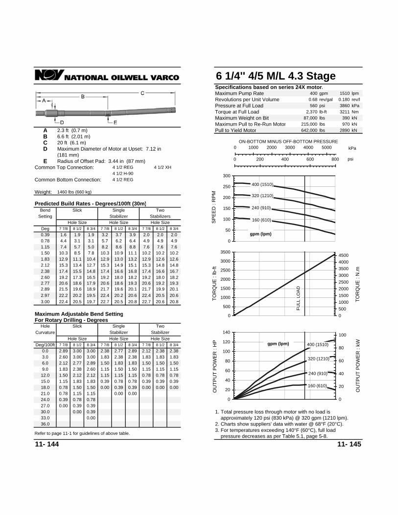
6 1/4'' 4/5 M/L 4.3 StageSpecifications based on series 24X motor.Maximum Pump Rate 400 gpm 1510 lpmRevolutions per Unit Volume 0.68 rev/gal 0.180 rev/lPressure at Full Load 560 psi 3860 kPaTorque at Full Load 2,370 lb-ft 3211 NmMaximum Weight on Bit 87,000 lbs 390 kNMaximum Pull to Re-Run Motor 215,000 lbs 970 kN
A 2.3 ft (0.7 m) Pull to Yield Motor 642,000 lbs 2890 kNB 6.6 ft (2.01 m)C 20 ft (6.1 m)D Maximum Diameter of Motor at Upset: 7.12 in
(181 mm)E Radius of Offset Pad: 3.44 in (87 mm)
Common Top Connection: 4 1/2 REG 4 1/2 XH4 1/2 H-90
Common Bottom Connection: 4 1/2 REG
Weight: 1460 lbs (660 kg)
11- 144 11- 145
Predicted Build Rates - Degrees/100ft (30m)
Setting Stabilizer StabilizersBend
Hole SizeDeg 7 7/8 8 1/2 8 3/4
Slick
Hole Size Hole Size
Single Two
7 7/8 8 1/2 8 3/4 7 7/8
For Rotary Drilling - DegreesHole Slick
7 7/8 8 1/2 8 3/4Hole Size
Deg/100ft 7 7/8 8 1/2 8 3/40.0 2.89 3.00 3.00
33.030.0 0.00 0.3927.0 0.00 0.39 0.39
8 1/2 8 3/40.39 1.6 1.9 1.9 3.2 3.7 3.9 2.0 2.0 2.00.78 4.4 3.1 3.1 5.7 6.2 6.4 4.9 4.9 4.91.15 7.4 5.7 5.0 8.2 8.6 8.8 7.6 7.6 7.61.50 10.3 8.5 7.8 10.3 10.9 11.1 10.2 10.2 10.21.83 12.9 11.1 10.4 12.9 13.0 13.2 12.9 12.6 12.62.12 15.3 13.4 12.7 15.3 14.9 15.1 15.3 14.8 14.82.38 17.4 15.5 14.8 17.4 16.6 16.8 17.4 16.6 16.72.60 19.2 17.3 16.5 19.2 18.0 18.2 19.2 18.0 18.22.77 20.6 18.6 17.9 20.6 18.6 19.3 20.6 19.2 19.32.89 21.5 19.6 18.9 21.7 19.6 20.1 21.7 19.9 20.12.97 22.2 20.2 19.5 22.4 20.2 20.6 22.4 20.5 20.63.00 22.4 20.5 19.7 22.7 20.5 20.8 20.6
1.83 1.50
Maximum Adjustable Bend Setting
Single Two
2.892.38 2.77
20.822.7
Curvature Stabilizer Stabilizer
2.12 2.38 2.38
Hole Size Hole Size7 7/8 8 1/2 8 3/4
3.0 2.60 3.00 3.00
9.0 1.83 2.38 2.60 1.50 1.152.12 2.12 1.15 1.15
1.15 1.501.15 0.7812.0 1.50
15.0 1.15 1.83 1.83 0.39 0.78
1.83 2.381.50 1.83
2.38 1.83 1.83 1.836.0 2.12 2.77 2.89 1.50 1.50
0.78 0.781.15 1.15
0.78 0.39 0.39 0.3918.0 0.78 1.50 1.50 0.000.00 0.39 0.39 0.00
0.002. Charts show suppliers' data with water @ 68°F (20°C). approximately 120 psi (830 kPa) @ 320 gpm (1210 lpm).1. Total pressure loss through motor with no load is
Refer to page 11-1 for guidelines of above table.
24.0 0.39 0.78 0.78
36.03. For temperatures exceeding 140°F (60°C), full load pressure decreases as per Table 5.1, page 5-8.
21.0 0.78 0.00 0.001.15 1.150.00
160 (610)
240 (910)
320 (1210)
400 (1510)
0
50
100
150
200
250
300
SPEE
D :
RPM
gpm (lpm)
kPa0 1000 2000 3000 4000 5000ON-BOTTOM MINUS OFF-BOTTOM PRESSURE
psi0 200 400 600 800
FULL
LO
AD
0
500
1000
1500
2000
2500
3000
3500
TOR
QU
E : l
b-ft
050010001500200025003000350040004500
TOR
QU
E : N
.m
160 (610)
240 (910)
320 (1210)
400 (1510)
0
20
40
60
80
100
120
140
OU
TPU
T PO
WER
: H
P
0
20
40
60
80
100
OU
TPU
T PO
WER
: kWgpm (lpm)

6 1/4'' 4/5 M/L 7.5 StageSpecifications based on series 24X motor.Maximum Pump Rate 400 gpm 1510 lpmRevolutions per Unit Volume 0.68 rev/gal 0.180 rev/lPressure at Full Load 980 psi 6750 kPaTorque at Full Load 4,170 lb-ft 5650 NmMaximum Weight on Bit 87,000 lbs 390 kNMaximum Pull to Re-Run Motor 215,000 lbs 970 kN
A 2.3 ft (0.7 m) Pull to Yield Motor 642,000 lbs 2890 kNB 6.6 ft (2.01 m)C 26.6 ft (8.11 m)D Maximum Diameter of Motor at Upset: 7.12 in
(181 mm)E Radius of Offset Pad: 3.44 in (87 mm)
Common Top Connection: 4 1/2 REG 4 1/2 XH4 1/2 H-90
Common Bottom Connection: 4 1/2 REG
Weight: 1940 lbs (880 kg)
11- 146 11- 147
Predicted Build Rates - Degrees/100ft (30m)
Setting Stabilizer StabilizersBend
Hole SizeDeg 7 7/8 8 1/2 8 3/4
Hole Size Hole Size7 7/8 8 1/2 8 3/4 7 7/8
For Rotary Drilling - DegreesHole Slick
7 7/8 8 1/2 8 3/4Hole Size
Deg/100ft 7 7/8 8 1/2 8 3/40.0 3.00 3.00 3.00
Slick Single
27.525.0 0.00 0.3922.5 0.00 0.39 0.39
Two
8 1/2 8 3/40.39 1.3 1.4 1.2 2.4 2.7 2.8 1.7 1.7 1.70.78 3.3 2.5 2.5 4.5 4.8 4.9 4.1 4.1 4.11.15 5.7 4.3 3.8 6.5 6.8 6.9 6.3 6.3 6.31.50 7.9 6.6 6.0 8.4 8.7 8.8 8.4 8.4 8.41.83 10.0 8.6 8.1 10.0 10.5 10.6 10.2 10.4 10.42.12 11.9 10.5 9.9 11.9 12.0 12.1 11.9 12.0 12.12.38 13.6 12.1 11.6 13.6 13.4 13.5 13.6 13.4 13.52.60 15.0 13.5 12.9 15.0 14.6 14.7 15.0 14.6 14.72.77 16.1 14.6 14.0 16.1 15.6 15.6 16.1 15.6 15.62.89 16.8 15.3 14.8 16.8 16.2 16.3 16.8 16.2 16.32.97 17.3 15.9 15.3 17.3 16.6 16.7 17.3 16.6 16.73.00 17.5 16.0 15.5 17.5 16.8 16.9 16.8
2.38 1.50
Maximum Adjustable Bend Setting
Single Two
3.002.60 3.00
16.917.5
Curvature Stabilizer Stabilizer
2.38 2.89 3.00
Hole Size Hole Size7 7/8 8 1/2 8 3/4
2.5 3.00 3.00 3.00
7.5 2.12 2.60 2.77 1.83 1.152.12 2.38 1.15 1.50
1.50 1.831.50 1.1510.0 1.83
12.5 1.50 1.83 2.12 0.78 1.15
2.12 2.771.83 2.38
2.77 2.12 2.38 2.385.0 2.60 3.00 3.00 2.12 2.12
1.15 1.151.50 1.50
1.15 0.78 0.78 0.7815.0 1.15 1.50 1.50 0.390.39 0.39 0.78 0.39
0.002. Charts show suppliers' data with water @ 68°F (20°C). approximately 170 psi (1170 kPa) @ 320 gpm (1210 lpm).1. Total pressure loss through motor with no load is
0.0020.0 0.39 0.78 0.78
30.0
0.00
3. For temperatures exceeding 140°F (60°C), full load pressure decreases as per Table 5.1, page 5-8.Refer to page 11-1 for guidelines of above table.
17.5 0.78 0.00 0.00 0.00 0.001.15 1.150.39
160 (610)
240 (910)
320 (1210)
400 (1510)
0
50
100
150
200
250
300
SPEE
D :
RPM
gpm (lpm)
kPa0 2000 4000 6000 8000ON-BOTTOM MINUS OFF-BOTTOM PRESSURE
psi0 200 400 600 800 1000 1200 1400
FULL
LO
AD
0500
100015002000250030003500400045005000550060006500
TOR
QU
E : l
b-ft
0
1000
2000
3000
4000
5000
6000
7000
8000
TOR
QU
E : N
.m
160 (610)
240 (910)
320 (1210)
400 (1510)
0
40
80
120
160
200
240
OU
TPU
T PO
WER
: H
P
0
40
80
120
160
OU
TPU
T PO
WER
: kWgpm (lpm)

6 1/4'' 5/6 M/L 5.0 StageSpecifications based on series 24X motor.Maximum Pump Rate 400 gpm 1510 lpmRevolutions per Unit Volume 0.73 rev/gal 0.193 rev/lPressure at Full Load 650 psi 4480 kPaTorque at Full Load 2,820 lb-ft 3821 NmMaximum Weight on Bit 87,000 lbs 390 kNMaximum Pull to Re-Run Motor 215,000 lbs 970 kN
A 2.3 ft (0.7 m) Pull to Yield Motor 642,000 lbs 2890 kNB 6.6 ft (2.01 m)C 19.9 ft (6.07 m)D Maximum Diameter of Motor at Upset: 7.12 in
(181 mm)E Radius of Offset Pad: 3.44 in (87 mm)
Common Top Connection: 4 1/2 REG 4 1/2 XH4 1/2 H90
Common Bottom Connection: 4 1/2 REG
Weight: 1450 lbs (660 kg)
11- 148 11- 149
Predicted Build Rates - Degrees/100ft (30m)
Setting Stabilizer StabilizersBend
Hole SizeDeg 7 7/8 8 1/2 8 3/4
Hole Size Hole Size7 7/8 8 1/2 8 3/4 7 7/8
For Rotary Drilling - DegreesHole Slick
7 7/8 8 1/2 8 3/4Hole Size
Deg/100ft 7 7/8 8 1/2 8 3/40.0 2.89 3.00 3.00
Slick Single
33.030.0 0.00 0.3927.0 0.00 0.39 0.39
Two
8 1/2 8 3/40.39 1.6 1.9 1.9 3.2 3.7 3.9 2.0 2.0 2.00.78 4.4 3.1 3.1 5.7 6.2 6.4 4.9 4.9 4.91.15 7.4 5.7 5.0 8.2 8.6 8.8 7.6 7.6 7.61.50 10.3 8.5 7.8 10.3 10.9 11.1 10.2 10.2 10.21.83 13.0 11.1 10.4 13.0 13.0 13.2 13.0 12.7 12.62.12 15.3 13.5 12.7 15.3 14.9 15.1 15.3 14.8 14.82.38 17.4 15.5 14.8 17.4 16.6 16.8 17.4 16.6 16.72.60 19.2 17.3 16.6 19.2 18.1 18.2 19.2 18.1 18.22.77 20.6 18.7 17.9 20.6 18.7 19.3 20.6 19.2 19.32.89 21.6 19.6 18.9 21.7 19.6 20.1 21.7 19.9 20.12.97 22.2 20.3 19.5 22.5 20.3 20.6 22.5 20.5 20.63.00 22.5 20.5 19.7 22.7 20.5 20.8 20.7
1.83 1.50
Maximum Adjustable Bend Setting
Single Two
2.892.38 2.77
20.822.7
Curvature Stabilizer Stabilizer
2.12 2.38 2.38
Hole Size Hole Size7 7/8 8 1/2 8 3/4
3.0 2.60 3.00 3.00
9.0 1.83 2.38 2.60 1.50 1.152.12 2.12 1.15 1.15
1.15 1.501.15 0.7812.0 1.50
15.0 1.15 1.83 1.83 0.39 0.78
1.83 2.381.50 1.83
2.38 1.83 1.83 1.836.0 2.12 2.77 2.89 1.50 1.50
0.78 0.781.15 1.15
0.78 0.39 0.39 0.3918.0 0.78 1.50 1.50 0.000.00 0.39 0.39 0.00
0.002. Charts show suppliers' data with water @ 68°F (20°C). approximately 140 psi (960 kPa) @ 340 gpm (1290 lpm).1. Total pressure loss through motor with no load is
24.0 0.39 0.78 0.78
36.03. For temperatures exceeding 140°F (60°C), full load pressure decreases as per Table 5.1, page 5-8.Refer to page 11-1 for guidelines of above table.
21.0 0.78 0.00 0.001.15 1.150.00
220 (830)
280 (1060)
340 (1290)
400 (1510)
0
50
100
150
200
250
300
SPEE
D :
RPM
gpm (lpm)
kPa0 1000 2000 3000 4000 5000 6000ON-BOTTOM MINUS OFF-BOTTOM PRESSURE
psi0 200 400 600 800 1000
FULL
LO
AD
0500
10001500200025003000350040004500
TOR
QU
E : l
b-ft
0
1000
2000
3000
4000
5000
6000
TOR
QU
E : N
.m
220 (830)
280 (1060)
340 (1290)
400 (1510)
020406080
100120140160180200220
OU
TPU
T PO
WER
: H
P
0
20
40
60
80
100
120
140
160
OU
TPU
T PO
WER
: kW
gpm (lpm)

6 1/4'' 5/6 M/L 5.5 StageSpecifications based on series 24X motor.Maximum Pump Rate 500 gpm 1890 lpmRevolutions per Unit Volume 0.46 rev/gal 0.122 rev/lPressure at Full Load 715 psi 4930 kPaTorque at Full Load 4,170 lb-ft 5650 NmMaximum Weight on Bit 87,000 lbs 390 kNMaximum Pull to Re-Run Motor 215,000 lbs 970 kN
A 2.3 ft (0.7 m) Pull to Yield Motor 642,000 lbs 2890 kNB 6.6 ft (2.01 m)C 26.6 ft (8.11 m)D Maximum Diameter of Motor at Upset: 7.12 in
(181 mm)E Radius of Offset Pad: 3.44 in (87 mm)
Common Top Connection: 4 1/2 REG 4 1/2 XH4 1/2 H90
Common Bottom Connection: 4 1/2 REG
Weight: 1940 lbs (880 kg)
11- 150 11- 151
0.000.0020.0 0.39 0.78 0.78
30.0
0.00 0.00 0.00 0.0017.5 0.78 1.15 1.15
2. Charts show suppliers' data with water @ 68°F (20°C). approximately 210 psi (1450 kPa) @ 400 gpm (1510 lpm).1. Total pressure loss through motor with no load is
0.39 0.390.39 0.39 0.78 0.3915.0 1.15 1.50 1.501.15 0.78 0.78 0.78
2.12 2.12
1.15 1.151.50 1.50
5.0 2.60 3.00 3.002.77 2.12 2.38 2.382.12 2.77
1.83 2.38
1.83 2.12 0.78 1.1510.0 1.8312.5 1.50
1.83 1.152.12 2.38 1.15 1.50
1.50 1.831.50 1.15
7.5 2.12 2.60 2.77
2.5 3.00 3.00 3.00
Stabilizer Stabilizer
2.38 2.89 3.00
Hole Size Hole Size7 7/8 8 1/2 8 3/4
Curvature
16.917.517.5 16.8
2.38 1.50
Maximum Adjustable Bend Setting
Single Two
3.002.60 3.00
16.9 16.83.00 17.5 16.1 15.516.7 17.3 16.7 16.72.97 17.3 15.9 15.3
16.8 16.2 16.317.3 16.7
16.1 15.6 15.62.89 16.8 15.4 14.8 16.8 16.2 16.3
15.0 14.6 14.72.77 16.1 14.6 14.0 16.1 15.6 15.6
13.6 13.5 13.52.60 15.0 13.5 13.0 15.0 14.6 14.7
11.9 12.0 12.12.38 13.6 12.1 11.6 13.6 13.5 13.5
10.2 10.5 10.42.12 11.9 10.5 9.9 11.9 12.0 12.1
8.4 8.4 8.41.83 10.0 8.6 8.1 10.0 10.5 10.6
6.3 6.3 6.31.50 7.9 6.6 6.0 8.4 8.7 8.8
4.1 4.1 4.11.15 5.7 4.3 3.8 6.5 6.8 6.9
1.7 1.7 1.70.78 3.3 2.5 2.5 4.5 4.8 4.9
8 1/2 8 3/4
Stabilizers
0.39 1.3 1.4 1.2 2.4 2.7 2.8
22.5 0.00 0.39 0.39
27.525.0 0.00 0.39
0.00
0.0 3.00 3.00 3.007 7/8 8 1/2 8 3/4
Hole SizeDeg/100ft 7 7/8 8 1/2 8 3/4
For Rotary Drilling - DegreesHole Slick
7 7/8 8 1/2 8 3/4 7 7/8Deg 7 7/8 8 1/2 8 3/4
Bend
Hole Size Hole Size Hole Size
Slick Single Two
3. For temperatures exceeding 140°F (60°C), full load pressure decreases as per Table 5.1, page 5-8.Refer to page 11-1 for guidelines of above table.
Predicted Build Rates - Degrees/100ft (30m)
Setting Stabilizer 200 (760)
300 (1140)
400 (1510)
500 (1890)
0
50
100
150
200
250
SPEE
D :
RPM
gpm (lpm)
kPa0 1000 2000 3000 4000 5000 6000ON-BOTTOM MINUS OFF-BOTTOM PRESSURE
psi0 200 400 600 800 1000
FULL
LO
AD
0
1000
2000
3000
4000
5000
6000
TOR
QU
E : l
b-ft
0
1000
2000
3000
4000
5000
6000
7000
8000
TOR
QU
E : N
.m
200 (760)
300 (1140)
400 (1510)
500 (1890)
0
50
100
150
200
250
OU
TPU
T PO
WER
: H
P
0
25
50
75
100
125
150
175
OU
TPU
T PO
WER
: kW
gpm (lpm)

6 1/4'' 7/8 M/L 2.8 StageSpecifications based on series 24X motor.Maximum Pump Rate 400 gpm 1510 lpmRevolutions per Unit Volume 0.34 rev/gal 0.090 rev/lPressure at Full Load 360 psi 2480 kPaTorque at Full Load 2,770 lb-ft 3753 NmMaximum Weight on Bit 87,000 lbs 390 kNMaximum Pull to Re-Run Motor 215,000 lbs 970 kN
A 2.3 ft (0.7 m) Pull to Yield Motor 642,000 lbs 2890 kNB 6.6 ft (2.01 m)C 20 ft (6.1 m)D Maximum Diameter of Motor at Upset: 7.12 in
(181 mm)E Radius of Offset Pad: 3.44 in (87 mm)
Common Top Connection: 4 1/2 REG 4 1/2 XH4 1/2 H-90
Common Bottom Connection: 4 1/2 REG
Weight: 1460 lbs (660 kg)
11- 152 11- 153
21.0 0.78 0.00 0.001.15 1.150.00
3. For temperatures exceeding 140°F (60°C), full load pressure decreases as per Table 5.1, page 5-8.Refer to page 11-1 for guidelines of above table.
24.0 0.39 0.78 0.78
36.0 2. Charts show suppliers' data with water @ 68°F (20°C). approximately 110 psi (760 kPa) @ 340 gpm (1290 lpm).1. Total pressure loss through motor with no load is
0.00
0.000.00 0.39 0.39 0.0018.0 0.78 1.50 1.500.78 0.39 0.39 0.39
1.50 1.50
0.78 0.781.15 1.15
6.0 2.12 2.77 2.892.38 1.83 1.83 1.831.83 2.38
1.50 1.83
1.83 1.83 0.39 0.7812.0 1.5015.0 1.15
1.50 1.152.12 2.12 1.15 1.15
1.15 1.501.15 0.78
9.0 1.83 2.38 2.60
3.0 2.60 3.00 3.00
Stabilizer Stabilizer
2.12 2.38 2.38
Hole Size Hole Size7 7/8 8 1/2 8 3/4
Curvature
20.822.7
1.83 1.50
Maximum Adjustable Bend Setting
Single Two
2.892.38 2.77
20.5 20.63.00 22.4 20.5 19.7 22.7 20.5 20.8 20.6
19.9 20.12.97 22.2 20.2 19.5 22.4 20.2 20.6 22.4
19.2 19.32.89 21.5 19.6 18.9 21.7 19.6 20.1 21.7
18.0 18.22.77 20.6 18.6 17.9 20.6 18.6 19.3 20.6
16.6 16.72.60 19.2 17.3 16.5 19.2 18.0 18.2 19.2
14.8 14.82.38 17.4 15.5 14.8 17.4 16.6 16.8 17.4
12.6 12.62.12 15.3 13.4 12.7 15.3 14.9 15.1 15.3
10.2 10.21.83 12.9 11.1 10.4 12.9 13.0 13.2 12.9
7.6 7.61.50 10.3 8.5 7.8 10.3 10.9 11.1 10.2
4.9 4.91.15 7.4 5.7 5.0 8.2 8.6 8.8 7.6
2.0 2.00.78 4.4 3.1 3.1 5.7 6.2 6.4 4.9
3.2 3.7 3.9 2.00.39 1.6 1.9 1.9
Two
8 1/2 8 3/4
27.0 0.00 0.39 0.39
33.030.0 0.00 0.39
Slick Single
0.0 2.89 3.00 3.007 7/8 8 1/2 8 3/4
Hole SizeDeg/100ft 7 7/8 8 1/2 8 3/4
For Rotary Drilling - DegreesHole Slick
Hole Size Hole Size7 7/8 8 1/2 8 3/4 7 7/8
Hole SizeDeg 7 7/8 8 1/2 8 3/4
Predicted Build Rates - Degrees/100ft (30m)
Setting Stabilizer StabilizersBend 220 (830)
280 (1060)
340 (1290)
400 (1510)
0
20
40
60
80
100
120
140
SPEE
D :
RPM
gpm (lpm)
kPa0 1000 2000 3000 4000ON-BOTTOM MINUS OFF-BOTTOM PRESSURE
0 100 200 300 400 500 600
FULL
LO
AD
0500
10001500200025003000350040004500
TOR
QU
E : l
b-ft
0
1000
2000
3000
4000
5000
6000
TOR
QU
E : N
.m
220 (830)
280 (1060)
340 (1290)
400 (1510)
0
10
20
30
40
50
60
70
80
90
OU
TPU
T PO
WER
: H
P
0
10
20
30
40
50
60
OU
TPU
T PO
WER
: kW
gpm (lpm)
psi

6 1/4'' 7/8 M/L 2.9 StageSpecifications based on series 24X motor.Maximum Pump Rate 500 gpm 1890 lpmRevolutions per Unit Volume 0.17 rev/gal 0.045 rev/lPressure at Full Load 380 psi 2620 kPaTorque at Full Load 5,590 lb-ft 7574 NmMaximum Weight on Bit 87,000 lbs 390 kNMaximum Pull to Re-Run Motor 215,000 lbs 970 kN
A 2.3 ft (0.7 m) Pull to Yield Motor 642,000 lbs 2890 kNB 6.6 ft (2.01 m)C 28 ft (8.53 m)D Maximum Diameter of Motor at Upset: 7.12 in
(181 mm)E Radius of Offset Pad: 3.44 in (87 mm)
Common Top Connection: 4 1/2 REG 4 1/2 XH4 1/2 H-90
Common Bottom Connection: 4 1/2 REG
Weight: 2040 lbs (930 kg)
11- 154 11- 155
17.5 0.78 0.00 0.00 0.00 0.001.15 1.150.39
3. For temperatures exceeding 140°F (60°C), full load pressure decreases as per Table 5.1, page 5-8.Refer to page 11-1 for guidelines of above table.
0.000.0020.0 0.39 0.78 0.78
30.0 2. Charts show suppliers' data with water @ 68°F (20°C). approximately 120 psi (830 kPa) @ 400 gpm (1510 lpm).1. Total pressure loss through motor with no load is
0.390.39 0.39 0.78 0.3915.0 1.15 1.50 1.501.15 0.78 0.78 0.78
2.12 2.12
1.15 1.151.50 1.50
5.0 2.60 3.00 3.002.89 2.12 2.60 2.602.12 2.89
1.83 2.38
1.83 2.12 1.15 1.1510.0 1.8312.5 1.50
1.83 1.152.12 2.38 1.50 1.50
1.50 1.831.50 1.15
7.5 2.12 2.60 2.77
2.5 3.00 3.00 3.00
Stabilizer Stabilizer
2.38 3.00 3.00
Hole Size Hole Size7 7/8 8 1/2 8 3/4
Curvature
16.216.8
2.38 1.83
Maximum Adjustable Bend Setting
Single Two
3.002.60 3.00
16.0 16.13.00 16.8 15.3 14.8 16.8 16.2 16.2 16.2
15.6 15.72.97 16.6 15.2 14.6 16.6 16.0 16.1 16.6
15.0 15.02.89 16.1 14.7 14.1 16.1 15.6 15.7 16.1
14.1 14.12.77 15.3 14.0 13.4 15.3 15.0 15.0 15.3
12.9 13.02.60 14.3 12.9 12.4 14.3 14.1 14.1 14.3
11.6 11.62.38 13.0 11.6 11.1 13.0 12.9 13.0 13.0
10.1 10.12.12 11.4 10.0 9.5 11.4 11.6 11.6 11.4
8.1 8.11.83 9.6 8.3 7.7 9.8 10.1 10.1 9.8
6.1 6.11.50 7.6 6.3 5.7 8.1 8.3 8.4 8.1
3.9 3.91.15 5.4 4.1 3.6 6.2 6.5 6.6 6.1
1.6 1.60.78 3.2 2.4 2.4 4.3 4.6 4.7 3.9
2.2 2.5 2.6 1.60.39 1.2 1.4 1.2
Two
8 1/2 8 3/4
22.5 0.00 0.39 0.39
27.525.0 0.00 0.00
Slick Single
0.0 3.00 3.00 3.007 7/8 8 1/2 8 3/4
Hole SizeDeg/100ft 7 7/8 8 1/2 8 3/4
For Rotary Drilling - DegreesHole Slick
Hole Size Hole Size7 7/8 8 1/2 8 3/4 7 7/8
Hole SizeDeg 7 7/8 8 1/2 8 3/4
Predicted Build Rates - Degrees/100ft (30m)
Setting Stabilizer StabilizersBend
200 (760)
300 (1140)
400 (1510)
500 (1890)
0102030405060708090
SPEE
D :
RPM
gpm (lpm)
0 1000 2000 3000 4000ON-BOTTOM MINUS OFF-BOTTOM PRESSURE
kPa
0 100 200 300 400 500 600
FULL
LO
AD
0100020003000400050006000700080009000
10000
TOR
QU
E : l
b-ft
0
2000
4000
6000
8000
10000
12000
TOR
QU
E : N
.m
200 (760)
300 (1140)
400 (1510)
500 (1890)
0
10
20
30
40
50
60
70
80
90
OU
TPU
T PO
WER
: H
P
0
10
20
30
40
50
60
OU
TPU
T PO
WER
: kW
gpm (lpm)
psi

6 1/4'' 7/8 M/L 3.0 StageSpecifications based on series 24X motor.Maximum Pump Rate 400 gpm 1510 lpmRevolutions per Unit Volume 0.39 rev/gal 0.104 rev/lPressure at Full Load 390 psi 2690 kPaTorque at Full Load 3,120 lb-ft 4228 NmMaximum Weight on Bit 87,000 lbs 390 kNMaximum Pull to Re-Run Motor 215,000 lbs 970 kN
A 2.3 ft (0.7 m) Pull to Yield Motor 642,000 lbs 2890 kNB 6.6 ft (2.01 m)C 20 ft (6.1 m)D Maximum Diameter of Motor at Upset: 7.12 in
(181 mm)E Radius of Offset Pad: 3.44 in (87 mm)
Common Top Connection: 4 1/2 REG 4 1/2 XH4 1/2 H-90
Common Bottom Connection: 4 1/2 REG
Weight: 1460 lbs (660 kg)
11- 156 11- 157
21.0 0.78 0.00 0.001.15 1.150.00
3. For temperatures exceeding 140°F (60°C), full load pressure decreases as per Table 5.1, page 5-8.Refer to page 11-1 for guidelines of above table.
24.0 0.39 0.78 0.78
36.0 2. Charts show suppliers' data with water @ 68°F (20°C). approximately 115 psi (790 kPa) @ 340 gpm (1290 lpm).1. Total pressure loss through motor with no load is
0.00
0.000.00 0.39 0.39 0.0018.0 0.78 1.50 1.500.78 0.39 0.39 0.39
1.50 1.50
0.78 0.781.15 1.15
6.0 2.12 2.77 2.892.38 1.83 1.83 1.831.83 2.38
1.50 1.83
1.83 1.83 0.39 0.7812.0 1.5015.0 1.15
1.50 1.152.12 2.12 1.15 1.15
1.15 1.501.15 0.78
9.0 1.83 2.38 2.60
3.0 2.60 3.00 3.00
Stabilizer Stabilizer
2.12 2.38 2.38
Hole Size Hole Size7 7/8 8 1/2 8 3/4
Curvature
20.822.7
1.83 1.50
Maximum Adjustable Bend Setting
Single Two
2.892.38 2.77
20.5 20.63.00 22.5 20.5 19.7 22.7 20.5 20.8 20.7
19.9 20.12.97 22.2 20.3 19.5 22.5 20.3 20.6 22.5
19.2 19.32.89 21.6 19.6 18.9 21.7 19.6 20.1 21.7
18.1 18.22.77 20.6 18.7 17.9 20.6 18.7 19.3 20.6
16.6 16.72.60 19.2 17.3 16.6 19.2 18.1 18.2 19.2
14.8 14.82.38 17.4 15.5 14.8 17.4 16.6 16.8 17.4
12.7 12.62.12 15.3 13.5 12.7 15.3 14.9 15.1 15.3
10.2 10.21.83 13.0 11.1 10.4 13.0 13.0 13.2 13.0
7.6 7.61.50 10.3 8.5 7.8 10.3 10.9 11.1 10.2
4.9 4.91.15 7.4 5.7 5.0 8.2 8.6 8.8 7.6
2.0 2.00.78 4.4 3.1 3.1 5.7 6.2 6.4 4.9
3.2 3.7 3.9 2.00.39 1.6 1.9 1.9
Two
8 1/2 8 3/4
27.0 0.00 0.39 0.39
33.030.0 0.00 0.39
Slick Single
0.0 2.89 3.00 3.007 7/8 8 1/2 8 3/4
Hole SizeDeg/100ft 7 7/8 8 1/2 8 3/4
For Rotary Drilling - DegreesHole Slick
Hole Size Hole Size7 7/8 8 1/2 8 3/4 7 7/8
Hole SizeDeg 7 7/8 8 1/2 8 3/4
Predicted Build Rates - Degrees/100ft (30m)
Setting Stabilizer StabilizersBend 220 (830)
280 (1060)
340 (1290)
400 (1510)
0
20
40
60
80
100
120
140
160
SPEE
D :
RPM
gpm (lpm)
kPa0 500 1000 1500 2000 2500 3000 3500 4000ON-BOTTOM MINUS OFF-BOTTOM PRESSURE
0 100 200 300 400 500 600
FULL
LO
AD
0500
100015002000250030003500400045005000
TOR
QU
E : l
b-ft
0
1000
2000
3000
4000
5000
6000
TOR
QU
E : N
.m
220 (830)
280 (1060)
340 (1290)
400 (1510)
0102030405060708090
100110120
OU
TPU
T PO
WER
: H
P
0
10
20
30
40
50
60
70
80
OU
TPU
T PO
WER
: kW
gpm (lpm)
psi

6 1/4'' 7/8 M/L 4.8 StageSpecifications based on series 24X motor.Maximum Pump Rate 400 gpm 1510 lpmRevolutions per Unit Volume 0.35 rev/gal 0.092 rev/lPressure at Full Load 620 psi 4270 kPaTorque at Full Load 4,840 lb-ft 6558 NmMaximum Weight on Bit 87,000 lbs 390 kNMaximum Pull to Re-Run Motor 215,000 lbs 970 kN
A 2.3 ft (0.7 m) Pull to Yield Motor 642,000 lbs 2890 kNB 6.6 ft (2.01 m)C 26.6 ft (8.11 m)D Maximum Diameter of Motor at Upset: 7.12 in
(181 mm)E Radius of Offset Pad: 3.44 in (87 mm)
Common Top Connection: 4 1/2 REG 4 1/2 XH4 1/2 H-90
Common Bottom Connection: 4 1/2 REG
Weight: 1940 lbs (880 kg)
11- 158 11- 159
0.000.0020.0 0.39 0.78 0.78
30.0
0.00 0.00 0.00 0.0017.5 0.78 1.15 1.15
2. Charts show suppliers' data with water @ 68°F (20°C). approximately 140 psi (960 kPa) @ 320 gpm (1210 lpm).1. Total pressure loss through motor with no load is
1.15 0.781.15 1.15
0.39 0.390.78 0.78
2.12 2.12
0.39 0.39 0.78 0.3915.0 1.15 1.50 1.50
1.50 1.505.0 2.60 3.00 3.00
1.83 1.151.50 1.83
2.77 2.12 2.38 2.382.12 2.771.83 2.38
1.83 2.12 0.78 1.1510.0 1.8312.5 1.50
1.50 1.157.5 2.12 2.60 2.77
2.12 2.38 1.15 1.50
2.5 3.00 3.00 3.00
Stabilizer Stabilizer
2.38 2.89 3.00
Hole Size Hole Size7 7/8 8 1/2 8 3/4
Curvature
16.917.517.5 16.8
2.38 1.50
Maximum Adjustable Bend Setting
Single Two
3.002.60 3.00
16.9 16.83.00 17.5 16.1 15.516.7 17.3 16.7 16.72.97 17.3 15.9 15.3
16.8 16.2 16.317.3 16.7
16.1 15.6 15.62.89 16.8 15.4 14.8 16.8 16.2 16.3
15.0 14.7 14.72.77 16.1 14.6 14.0 16.1 15.6 15.6
13.6 13.5 13.52.60 15.0 13.5 13.0 15.0 14.7 14.7
11.9 12.1 12.12.38 13.6 12.1 11.6 13.6 13.5 13.5
10.2 10.5 10.52.12 11.9 10.5 9.9 11.9 12.1 12.1
8.4 8.4 8.41.83 10.0 8.7 8.1 10.0 10.5 10.6
6.3 6.3 6.31.50 7.9 6.6 6.0 8.4 8.7 8.8
4.1 4.1 4.11.15 5.7 4.3 3.8 6.5 6.8 6.9
1.7 1.7 1.70.78 3.3 2.5 2.5 4.5 4.8 4.9
8 1/2 8 3/4
Stabilizers
0.39 1.3 1.4 1.2 2.4 2.7 2.8
22.5 0.00 0.39 0.39
27.525.0 0.00 0.39
0.00
0.0 3.00 3.00 3.007 7/8 8 1/2 8 3/4
Hole SizeDeg/100ft 7 7/8 8 1/2 8 3/4
For Rotary Drilling - DegreesHole Slick
7 7/8 8 1/2 8 3/4 7 7/8Deg 7 7/8 8 1/2 8 3/4
Bend
Hole Size Hole Size Hole Size
Slick Single Two
3. For temperatures exceeding 140°F (60°C), full load pressure decreases as per Table 5.1, page 5-8.Refer to page 11-1 for guidelines of above table.
Predicted Build Rates - Degrees/100ft (30m)
Setting Stabilizer 160 (610)
240 (910)
320 (1210)
400 (1510)
0
20
40
60
80
100
120
140
SPEE
D :
RPM
gpm (lpm)
kPa0 1000 2000 3000 4000 5000 6000ON-BOTTOM MINUS OFF-BOTTOM PRESSURE
psi0 200 400 600 800 1000
FULL
LO
AD
0
1000
2000
3000
4000
5000
6000
7000
8000
TOR
QU
E : l
b-ft
0
2000
4000
6000
8000
10000
TOR
QU
E : N
.m
160 (610)
240 (910)
320 (1210)
400 (1510)
0
25
50
75
100
125
150
OU
TPU
T PO
WER
: H
P
0
20
40
60
80
100
OU
TPU
T PO
WER
: kW
gpm (lpm)

6 3/4'' 1/2 H/S 3.0 StageSpecifications based on series 24X motor.Maximum Pump Rate 500 gpm 1890 lpmRevolutions per Unit Volume 0.97 rev/gal 0.256 rev/lPressure at Full Load 390 psi 2690 kPaTorque at Full Load 990 lb-ft 1341 NmMaximum Weight on Bit 122,000 lbs 550 kNMaximum Pull to Re-Run Motor 277,000 lbs 1250 kN
A 2.3 ft (0.7 m) Pull to Yield Motor 672,000 lbs 3020 kNB 6.6 ft (2.01 m)C 20.8 ft (6.34 m)D Maximum Diameter of Motor at Upset: 7.63 in
(194 mm)E Radius of Offset Pad: 3.63 in (92 mm)
Common Top Connection: 4 1/2 REG 4 1/2 IF4 1/2 H-90 5 H-90
Common Bottom Connection: 4 1/2 REG 6 5/8 REG
Weight: 1770 lbs (800 kg)
11- 160 11- 161
3. For temperatures exceeding 140°F (60°C), full load pressure decreases as per Table 5.1, page 5-8.Refer to page 11-1 for guidelines of above table.
Predicted Build Rates - Degrees/100ft (30m)
Setting StabilizerHole Size Hole Size
Slick Single TwoBend
Hole SizeDeg 8 1/2 8 3/4 9 7/8 8 1/2 8 3/4 9 7/8 8 1/2
For Rotary Drilling - DegreesHole Slick
8 1/2 8 3/4 9 7/8Hole Size
Deg/100ft 8 1/2 8 3/4 9 7/80.0 3.00 3.00 3.00
38.535.0 0.0031.5 0.39
8 3/4 9 7/8
Stabilizers
0.39 1.5 1.8 1.5 3.0 3.2 4.0 1.9 1.9 1.90.78 3.4 3.0 2.9 5.5 5.6 6.4 4.6 4.6 4.61.15 6.3 5.6 4.3 7.8 7.9 8.6 7.3 7.3 7.31.50 9.0 8.3 5.6 10.0 10.1 10.8 9.8 9.8 9.71.83 11.5 10.8 7.9 12.0 12.2 12.8 12.0 12.1 12.12.12 13.8 13.1 10.1 13.8 14.0 14.6 13.9 14.0 14.12.38 15.8 15.1 12.0 15.8 15.1 16.2 15.8 15.6 16.02.60 17.5 16.7 13.7 17.5 16.7 17.5 17.5 17.0 17.52.77 18.8 18.1 14.9 18.8 18.1 18.5 18.8 18.1 18.52.89 19.7 19.0 15.8 19.7 19.0 19.3 19.7 19.0 19.3
20.3 19.62.97 20.3 19.6 16.4 19.8 20.3 19.6 19.820.0 19.83.00 20.5 19.8 16.7
1.50 1.15
Maximum Adjustable Bend Setting
Single Two
2.602.60 2.77
20.020.520.5 19.8
Curvature Stabilizer Stabilizer
2.12 2.38 2.12
Hole Size Hole Size8 1/2 8 3/4 9 7/8
3.5 2.77 2.89 3.00
10.5 1.83 2.12 2.89 1.15 0.391.50 2.38 0.39 0.39
0.78 0.780.39 0.0014.0 1.50
17.5 1.15 1.15 2.12 0.00 0.00
2.12 1.831.15 1.50
2.12 1.83 1.50 1.507.0 2.38 2.38 3.00 1.15 1.15
0.00 0.000.39 0.39
0.0021.0 0.78 0.78 1.50
2. Charts show suppliers' data with water @ 68°F (20°C). approximately 180 psi (1240 kPa) @ 400 gpm (1510 lpm).1. Total pressure loss through motor with no load is
24.5 0.39 0.39 1.1528.0 0.00 0.00 0.78
42.0
200 (760)
300 (1140)
400 (1510)
500 (1890)
050
100150200250300350400450500
SPEE
D :
RPM
gpm (lpm)
kPa0 1000 2000 3000 4000ON-BOTTOM MINUS OFF-BOTTOM PRESSURE
psi0 100 200 300 400 500 600
FULL
LO
AD
0
200
400
600
800
1000
1200
1400
1600
TOR
QU
E : l
b-ft
0
400
800
1200
1600
2000
TOR
QU
E : N
.m
200 (760)
300 (1140)
400 (1510)
500 (1890)
0
10
20
30
40
50
60
70
OU
TPU
T PO
WER
: H
P
0
10
20
30
40
50
OU
TPU
T PO
WER
: kW
gpm (lpm)

6 3/4'' 1/2 H/S 4.0 StageSpecifications based on series 24X motor.Maximum Pump Rate 500 gpm 1890 lpmRevolutions per Unit Volume 1.00 rev/gal 0.264 rev/lPressure at Full Load 520 psi 3580 kPaTorque at Full Load 1,580 lb-ft 2141 NmMaximum Weight on Bit 122,000 lbs 550 kNMaximum Pull to Re-Run Motor 277,000 lbs 1250 kN
A 2.3 ft (0.7 m) Pull to Yield Motor 672,000 lbs 3020 kNB 6.6 ft (2.01 m)C 24.1 ft (7.35 m)D Maximum Diameter of Motor at Upset: 7.63 in
(194 mm)E Radius of Offset Pad: 3.63 in (92 mm)
Common Top Connection: 4 1/2 REG 4 1/2 IF4 1/2 H-90 5 H-90
Common Bottom Connection: 4 1/2 REG 6 5/8 REG
Weight: 2050 lbs (930 kg)
11- 162 11- 163
Predicted Build Rates - Degrees/100ft (30m)
Setting Stabilizer StabilizersBend
Hole SizeDeg 8 1/2 8 3/4 9 7/8
Hole Size Hole Size8 1/2 8 3/4 9 7/8 8 1/2
For Rotary Drilling - DegreesHole Slick
8 1/2 8 3/4 9 7/8Hole Size
Deg/100ft 8 1/2 8 3/4 9 7/80.0 3.00 3.00 3.00
Slick Single
33.030.0 0.3927.0 0.00 0.00 0.78
Two
8 3/4 9 7/80.39 1.3 1.6 1.3 2.6 2.7 3.3 1.7 1.7 1.70.78 3.0 2.7 2.6 4.8 4.9 5.5 4.2 4.2 4.31.15 5.5 4.9 3.8 6.9 7.1 7.6 6.6 6.6 6.61.50 7.9 7.3 5.0 8.9 9.1 9.6 8.9 8.9 8.91.83 10.2 9.6 7.0 10.8 10.9 11.4 10.8 10.9 11.02.12 12.1 11.5 8.9 12.1 12.6 13.0 12.5 12.6 12.92.38 13.9 13.3 10.6 13.9 14.1 14.5 13.9 14.1 14.52.60 15.4 14.8 12.1 15.4 15.3 15.7 15.4 15.3 15.72.77 16.6 16.0 13.2 16.6 16.0 16.7 16.6 16.3 16.72.89 17.4 16.8 14.0 17.4 16.8 17.3 17.4 17.0 17.32.97 18.0 17.3 14.6 18.0 17.3 17.8 18.0 17.3 17.83.00 18.2 17.5 14.8 18.2 17.5 18.0 17.5
1.83 1.15
Maximum Adjustable Bend Setting
Single Two
2.772.60 2.89
18.018.2
Curvature Stabilizer Stabilizer
2.38 2.60 2.12
Hole Size Hole Size8 1/2 8 3/4 9 7/8
3.0 3.00 3.00 3.00
9.0 2.12 2.38 3.00 1.15 0.781.83 2.60 0.39 0.78
1.15 1.150.78 0.3912.0 1.83
15.0 1.50 1.50 2.12 0.00 0.00
2.12 2.121.50 1.50
2.12 2.12 1.83 1.836.0 2.60 2.77 3.00 1.15 1.15
0.39 0.390.78 0.78
0.39 0.00 0.00 0.0018.0 0.78 1.15 1.83
0.002. Charts show suppliers' data with water @ 68°F (20°C). approximately 180 psi (1240 kPa) @ 400 gpm (1510 lpm).1. Total pressure loss through motor with no load is
24.0 0.39 0.39 1.15
36.03. For temperatures exceeding 140°F (60°C), full load pressure decreases as per Table 5.1, page 5-8.Refer to page 11-1 for guidelines of above table.
21.0 0.39 0.78 1.50
200 (760)
300 (1140)
400 (1510)
500 (1890)
0
100
200
300
400
500
600
SPEE
D :
RPM
gpm (lpm)
kPa0 1000 2000 3000 4000 5000ON-BOTTOM MINUS OFF-BOTTOM PRESSURE
psi0 100 200 300 400 500 600 700 800
FULL
LO
AD
0
500
1000
1500
2000
2500
TOR
QU
E : l
b-ft
0
500
1000
1500
2000
2500
3000
TOR
QU
E : N
.m
200 (760)
300 (1140)
400 (1510)
500 (1890)
0
20
40
60
80
100
120
140
160
OU
TPU
T PO
WER
: H
P
0
20
40
60
80
100
OU
TPU
T PO
WER
: kW
gpm (lpm)

6 3/4'' 2/3 M/L 7.0 Stage (OS)Specifications based on series 24X motor.Maximum Pump Rate 600 gpm 2270 lpmRevolutions per Unit Volume 0.85 rev/gal 0.225 rev/lPressure at Full Load 910 psi 6270 kPaTorque at Full Load 2,820 lb-ft 3821 NmMaximum Weight on Bit 122,000 lbs 550 kNMaximum Pull to Re-Run Motor 277,000 lbs 1250 kN
A 2.3 ft (0.7 m) Pull to Yield Motor 672,000 lbs 3020 kNB 6.6 ft (2.01 m)C 26.2 ft (7.99 m)D Maximum Diameter of Motor at Upset: 7.63 in
(194 mm)E Radius of Offset Pad: 3.63 in (92 mm)
Common Top Connection: 4 1/2 REG 4 1/2 IF4 1/2 H-90 5 H-90
Common Bottom Connection: 4 1/2 REG 6 5/8 REG
Weight: 2230 lbs (1010 kg)
11- 164 11- 165
Predicted Build Rates - Degrees/100ft (30m)
Setting Stabilizer StabilizersBend
Hole SizeDeg 8 1/2 8 3/4 9 7/8
Hole Size Hole Size8 1/2 8 3/4 9 7/8 8 1/2
For Rotary Drilling - DegreesHole Slick
8 1/2 8 3/4 9 7/8Hole Size
Deg/100ft 8 1/2 8 3/4 9 7/80.0 3.00 3.00 3.00
Slick Single
33.030.0 0.0027.0 0.00 0.39
Two
8 3/4 9 7/80.39 1.3 1.4 1.2 2.4 2.5 3.0 1.6 1.6 1.70.78 2.7 2.5 2.4 4.5 4.6 5.1 4.0 4.0 4.01.15 5.1 4.6 3.6 6.5 6.6 7.1 6.3 6.3 6.31.50 7.3 6.8 4.7 8.4 8.5 8.9 8.4 8.4 8.41.83 9.4 8.9 6.5 10.2 10.3 10.7 10.2 10.3 10.42.12 11.3 10.7 8.3 11.7 11.8 12.2 11.7 11.8 12.12.38 13.0 12.4 9.9 13.0 13.2 13.6 13.2 13.2 13.62.60 14.4 13.8 11.3 14.4 14.4 14.8 14.4 14.4 14.82.77 15.4 14.9 12.3 15.4 15.3 15.7 15.4 15.3 15.72.89 16.2 15.6 13.1 16.2 15.6 16.3 16.2 16.0 16.32.97 16.7 16.1 13.6 16.7 16.1 16.7 16.7 16.4 16.73.00 16.9 16.3 13.8 16.9 16.3 16.9 16.6
1.83 1.50
Maximum Adjustable Bend Setting
Single Two
2.772.77 3.00
16.916.9
Curvature Stabilizer Stabilizer
2.60 2.60 2.38
Hole Size Hole Size8 1/2 8 3/4 9 7/8
3.0 3.00 3.00 3.00
9.0 2.12 2.38 3.00 1.15 0.781.83 2.60 0.39 0.78
1.15 1.150.78 0.3912.0 1.83
15.0 1.15 1.50 2.12 0.00 0.00
2.38 2.121.50 1.50
2.12 2.12 1.83 1.836.0 2.60 2.77 3.00 1.50 1.50
0.39 0.390.78 0.78
0.39 0.00 0.00 0.0018.0 0.78 1.15 1.83
2. Charts show suppliers' data with water @ 68°F (20°C). approximately 110 psi (760 kPa) @ 500 gpm (1890 lpm).1. Total pressure loss through motor with no load is
24.0 0.00 0.39 0.78
36.03. For temperatures exceeding 140°F (60°C), full load pressure decreases as per Table 5.1, page 5-8.Refer to page 11-1 for guidelines of above table.
21.0 0.39 0.78 1.15
300 (1140)
400 (1510)
500 (1890)
600 (2270)
0
100
200
300
400
500
600
SPEE
D :
RPM
gpm (lpm)
kPa0 2000 4000 6000 8000ON-BOTTOM MINUS OFF-BOTTOM PRESSURE
psi0 200 400 600 800 1000 1200
FULL
LO
AD
0
500
1000
1500
2000
2500
3000
3500
4000
TOR
QU
E : l
b-ft
0
1000
2000
3000
4000
5000
TOR
QU
E : N
.m
300 (1140)
400 (1510)
500 (1890)
600 (2270)
0
40
80
120
160
200
240
OU
TPU
T PO
WER
: H
P
0
25
50
75
100
125
150
175
OU
TPU
T PO
WER
: kW
gpm (lpm)

6 3/4'' 4/5 M/L 4.8 StageSpecifications based on series 24X motor.Maximum Pump Rate 600 gpm 2270 lpmRevolutions per Unit Volume 0.52 rev/gal 0.137 rev/lPressure at Full Load 620 psi 4270 kPaTorque at Full Load 3,440 lb-ft 4661 NmMaximum Weight on Bit 122,000 lbs 550 kNMaximum Pull to Re-Run Motor 277,000 lbs 1250 kN
A 2.3 ft (0.7 m) Pull to Yield Motor 672,000 lbs 3020 kNB 6.6 ft (2.01 m)C 21.9 ft (6.68 m)D Maximum Diameter of Motor at Upset: 7.63 in
(194 mm)E Radius of Offset Pad: 3.63 in (92 mm)
Common Top Connection: 4 1/2 REG 4 1/2 IF4 1/2 H-90 5 H-90
Common Bottom Connection: 4 1/2 REG 6 5/8 REG
Weight: 1860 lbs (840 kg)
11- 166 11- 167
24.5 0.39 0.39 1.15
3. For temperatures exceeding 140°F (60°C), full load pressure decreases as per Table 5.1, page 5-8.Refer to page 11-1 for guidelines of above table.
28.0 0.00 0.00 0.78
42.0 2. Charts show suppliers' data with water @ 68°F (20°C). approximately 190 psi (1310 kPa) @ 500 gpm (1890 lpm).1. Total pressure loss through motor with no load is
21.0 0.78 0.78 1.500.00
1.15 1.15
0.00 0.000.39 0.39
7.0 2.38 2.60 3.002.12 1.83 1.50 1.502.12 1.83
1.50 1.50
1.15 2.12 0.0014.0 1.5017.5 1.15
1.15 0.391.50 2.38 0.39 0.39
0.78 0.780.39 0.00
10.5 1.83 2.12 2.89
3.5 2.77 3.00 3.00
Stabilizer Stabilizer
2.38 2.38 2.12
Hole Size Hole Size8 1/2 8 3/4 9 7/8
Curvature
19.219.7
1.50 1.15
Maximum Adjustable Bend Setting
Single Two
2.602.60 2.77
18.8 19.13.00 19.7 19.0 16.0 19.7 19.0 19.2 19.0
18.2 18.62.97 19.5 18.8 15.8 19.5 18.8 19.1 19.5
17.3 17.92.89 18.9 18.2 15.2 18.9 18.2 18.6 18.9
16.4 16.92.77 18.0 17.3 14.3 18.0 17.3 17.9 18.0
15.1 15.52.60 16.7 16.0 13.1 16.7 16.0 16.9 16.7
13.5 13.72.38 15.1 14.4 11.5 15.1 15.1 15.6 15.1
11.7 11.72.12 13.2 12.5 9.6 13.2 13.5 14.0 13.4
9.5 9.41.83 11.0 10.4 7.6 11.6 11.7 12.3 11.6
7.1 7.01.50 8.6 7.9 5.4 9.6 9.7 10.3 9.5
4.5 4.51.15 6.0 5.4 4.1 7.5 7.6 8.3 7.1
1.8 1.80.78 3.2 2.9 2.8 5.2 5.4 6.1 4.5
2.8 3.0 3.7 1.80.39 1.5 1.7 1.4
Two
8 3/4 9 7/8
31.5 0.39
38.535.0 0.00
Slick Single
0.0 3.00 3.00 3.008 1/2 8 3/4 9 7/8
Hole SizeDeg/100ft 8 1/2 8 3/4 9 7/8
For Rotary Drilling - DegreesHole Slick
Hole Size Hole Size8 1/2 8 3/4 9 7/8 8 1/2
Hole SizeDeg 8 1/2 8 3/4 9 7/8
Predicted Build Rates - Degrees/100ft (30m)
Setting Stabilizer StabilizersBend
300 (1140)
400 (1510)
500 (1890)
600 (2270)
0
50
100
150
200
250
300
350
SPEE
D :
RPM
gpm (lpm)
kPa0 1000 2000 3000 4000 5000 6000ON-BOTTOM MINUS OFF-BOTTOM PRESSURE
psi0 200 400 600 800 1000
FULL
LO
AD
0
1000
2000
3000
4000
5000
6000
TOR
QU
E : l
b-ft
0
1000
2000
3000
4000
5000
6000
7000
8000
TOR
QU
E : N
.m
300 (1140)
400 (1510)
500 (1890)
600 (2270)
020406080
100120140160180200
OU
TPU
T PO
WER
: H
P
0
20
40
60
80
100
120
140
OU
TPU
T PO
WER
: kW
gpm (lpm)

6 3/4'' 4/5 M/L 7.0 StageSpecifications based on series 24X motor.Maximum Pump Rate 600 gpm 2270 lpmRevolutions per Unit Volume 0.50 rev/gal 0.132 rev/lPressure at Full Load 910 psi 6270 kPaTorque at Full Load 5,160 lb-ft 6992 NmMaximum Weight on Bit 122,000 lbs 550 kNMaximum Pull to Re-Run Motor 277,000 lbs 1250 kN
A 2.3 ft (0.7 m) Pull to Yield Motor 672,000 lbs 3020 kNB 6.6 ft (2.01 m)C 27 ft (8.23 m)D Maximum Diameter of Motor at Upset: 7.63 in
(194 mm)E Radius of Offset Pad: 3.63 in (92 mm)
Common Top Connection: 4 1/2 REG 4 1/2 IF4 1/2 H-90 5 H-90
Common Bottom Connection: 4 1/2 REG 6 5/8 REG
Weight: 2300 lbs (1040 kg)
11- 168 11- 169
Predicted Build Rates - Degrees/100ft (30m)
Setting Stabilizer StabilizersBend
Hole SizeDeg 8 1/2 8 3/4 9 7/8
Hole Size Hole Size8 1/2 8 3/4 9 7/8 8 1/2
For Rotary Drilling - DegreesHole Slick
8 1/2 8 3/4 9 7/8Hole Size
Deg/100ft 8 1/2 8 3/4 9 7/80.0 3.00 3.00 3.00
Slick Single
33.030.0 0.0027.0 0.39
Two
8 3/4 9 7/80.39 1.2 1.4 1.2 2.3 2.4 2.9 1.6 1.6 1.60.78 2.7 2.4 2.8 4.4 4.5 5.0 3.9 3.9 3.91.15 5.0 4.4 3.5 6.3 6.4 6.9 6.1 6.1 6.11.50 7.1 6.6 4.6 8.2 8.3 8.7 8.2 8.2 8.21.83 9.2 8.7 6.3 9.9 10.0 10.4 9.9 10.0 10.22.12 11.0 10.5 8.1 11.5 11.6 11.9 11.5 11.6 11.92.38 12.6 12.1 9.7 12.6 12.9 13.3 12.9 12.9 13.32.60 14.0 13.4 11.0 14.0 14.1 14.4 14.0 14.1 14.42.77 15.0 14.5 12.0 15.0 15.0 15.3 15.0 15.0 15.32.89 15.8 15.2 12.8 15.8 15.6 15.9 15.8 15.6 15.92.97 16.3 15.7 13.2 16.3 15.7 16.3 16.3 16.1 16.33.00 16.5 15.9 13.4 16.5 15.9 16.5 16.2
1.83 1.50
Maximum Adjustable Bend Setting
Single Two
2.892.77 3.00
16.516.5
Curvature Stabilizer Stabilizer
2.60 2.77 2.38
Hole Size Hole Size8 1/2 8 3/4 9 7/8
3.0 3.00 3.00 3.00
9.0 2.12 2.38 3.00 1.15 0.781.83 2.60 0.39 0.78
1.15 1.150.78 0.3912.0 1.83
15.0 1.15 1.50 2.12 0.00 0.00
2.38 2.121.50 1.50
2.38 2.12 1.83 1.836.0 2.60 2.77 3.00 1.50 1.50
0.39 0.390.78 0.78
0.00 0.00 0.00 0.0018.0 0.78 1.15 1.83
2. Charts show suppliers' data with water @ 68°F (20°C). approximately 210 psi (1450 kPa) @ 500 gpm (1890 lpm).1. Total pressure loss through motor with no load is
24.0 0.00 0.00 0.78
36.03. For temperatures exceeding 140°F (60°C), full load pressure decreases as per Table 5.1, page 5-8.Refer to page 11-1 for guidelines of above table.
21.0 0.39 0.78 1.15
300 (1140)
400 (1510)
500 (1890)
600 (2270)
0
50
100
150
200
250
300
350
SPEE
D :
RPM
gpm (lpm)
kPa0 2000 4000 6000 8000ON-BOTTOM MINUS OFF-BOTTOM PRESSURE
psi0 200 400 600 800 1000 1200
FULL
LO
AD
0
1000
2000
3000
4000
5000
6000
7000
TOR
QU
E : l
b-ft
0100020003000400050006000700080009000
TOR
QU
E : N
.m
300 (1140)
400 (1510)
500 (1890)
600 (2270)
0
50
100
150
200
250
300
350
OU
TPU
T PO
WER
: H
P
0
50
100
150
200
250
OU
TPU
T PO
WER
: kWgpm (lpm)

6 3/4'' 5/6 M/L 5.0 StageSpecifications based on series 24X motor.Maximum Pump Rate 600 gpm 2270 lpmRevolutions per Unit Volume 0.47 rev/gal 0.124 rev/lPressure at Full Load 650 psi 4480 kPaTorque at Full Load 4,380 lb-ft 5935 NmMaximum Weight on Bit 122,000 lbs 550 kNMaximum Pull to Re-Run Motor 277,000 lbs 1250 kN
A 2.3 ft (0.7 m) Pull to Yield Motor 672,000 lbs 3020 kNB 6.6 ft (2.01 m)C 21.9 ft (6.68 m)D Maximum Diameter of Motor at Upset: 7.63 in
(194 mm)E Radius of Offset Pad: 3.63 in (92 mm)
Common Top Connection: 4 1/2 REG 4 1/2 IF4 1/2 H-90 5 H-90
Common Bottom Connection: 4 1/2 REG 6 5/8 REG
Weight: 1860 lbs (840 kg)
11- 170 11- 171
3. For temperatures exceeding 140°F (60°C), full load pressure decreases as per Table 5.1, page 5-8.
28.0 0.00 0.00 0.78
42.0
24.5 0.39 0.39 1.15
2. Charts show suppliers' data with water @ 68°F (20°C). approximately 200 psi (1380 kPa) @ 470 gpm (1780 lpm).1. Total pressure loss through motor with no load is
21.0 0.78 0.78 1.500.00
1.15 1.15
0.00 0.000.39 0.39
7.0 2.38 2.60 3.002.12 1.83 1.50 1.502.12 1.83
1.50 1.50
1.15 2.12 0.0014.0 1.5017.5 1.15
1.15 0.391.50 2.38 0.39 0.39
0.78 0.780.39 0.00
10.5 1.83 2.12 2.89
3.5 2.77 3.00 3.00
Stabilizer Stabilizer
2.38 2.38 2.12
Hole Size Hole Size8 1/2 8 3/4 9 7/8
Curvature
19.219.7
1.50 1.15
Maximum Adjustable Bend Setting
Single Two
2.602.60 2.77
18.8 19.13.00 19.7 19.0 16.0 19.7 19.0 19.2 19.0
18.2 18.62.97 19.5 18.8 15.8 19.5 18.8 19.1 19.5
17.3 17.92.89 18.9 18.2 15.2 18.9 18.2 18.6 18.9
16.4 16.92.77 18.0 17.3 14.3 18.0 17.3 17.9 18.0
15.1 15.52.60 16.7 16.0 13.1 16.7 16.0 16.9 16.7
13.5 13.72.38 15.1 14.4 11.5 15.1 15.1 15.6 15.1
11.7 11.72.12 13.2 12.5 9.6 13.2 13.5 14.0 13.4
9.5 9.41.83 11.0 10.4 7.6 11.6 11.7 12.3 11.6
7.1 7.01.50 8.6 7.9 5.4 9.6 9.7 10.3 9.5
4.5 4.51.15 6.0 5.4 4.1 7.5 7.6 8.3 7.1
1.8 1.80.78 3.2 2.9 2.8 5.2 5.4 6.1 4.5
2.8 3.0 3.7 1.80.39 1.5 1.7 1.4
Two
8 3/4 9 7/8
31.5 0.39
38.535.0 0.00
Refer to page 11-1 for guidelines of above table.
Slick Single
0.0 3.00 3.00 3.008 1/2 8 3/4 9 7/8
Hole SizeDeg/100ft 8 1/2 8 3/4 9 7/8
For Rotary Drilling - DegreesHole Slick
Hole Size Hole Size8 1/2 8 3/4 9 7/8 8 1/2
Hole SizeDeg 8 1/2 8 3/4 9 7/8
Predicted Build Rates - Degrees/100ft (30m)
Setting Stabilizer StabilizersBend
210 (790)
340 (1290)
470 (1780)
600 (2270)
0
50
100
150
200
250
300
SPEE
D :
RPM
gpm (lpm)
kPa0 1000 2000 3000 4000 5000 6000ON-BOTTOM MINUS OFF-BOTTOM PRESSURE
psi0 200 400 600 800 1000
FULL
LO
AD
0
1000
2000
3000
4000
5000
6000
7000
TOR
QU
E : l
b-ft
0100020003000400050006000700080009000
TOR
QU
E : N
.m
210 (790)
340 (1290)
470 (1780)
600 (2270)
0
50
100
150
200
250
300
350
OU
TPU
T PO
WER
: H
P
0
50
100
150
200
250
OU
TPU
T PO
WER
: kW
gpm (lpm)

6 3/4'' 6/7 M/L 5.0 StageSpecifications based on series 24X motor.Maximum Pump Rate 600 gpm 2270 lpmRevolutions per Unit Volume 0.29 rev/gal 0.077 rev/lPressure at Full Load 650 psi 4480 kPaTorque at Full Load 5,410 lb-ft 7331 NmMaximum Weight on Bit 122,000 lbs 550 kNMaximum Pull to Re-Run Motor 277,000 lbs 1250 kN
A 2.3 ft (0.7 m) Pull to Yield Motor 672,000 lbs 3020 kNB 6.6 ft (2.01 m)C 26.2 ft (7.99 m)D Maximum Diameter of Motor at Upset: 7.63 in
(194 mm)E Radius of Offset Pad: 3.63 in (92 mm)
Common Top Connection: 4 1/2 REG 4 1/2 IF4 1/2 H-90 5 H-90
Common Bottom Connection: 4 1/2 REG 6 5/8 REG
Weight: 2230 lbs (1010 kg)
11- 172 11- 173
24.0 0.00 0.39 0.78
36.0
21.0 0.39 0.78 1.15
2. Charts show suppliers' data with water @ 68°F (20°C). approximately 170 psi (1170 kPa) @ 500 gpm (1890 lpm).1. Total pressure loss through motor with no load is
18.0 0.78 1.15 1.830.39 0.00 0.00 0.00
1.50 1.50
0.39 0.390.78 0.78
6.0 2.60 2.77 3.002.12 2.12 1.83 1.832.38 2.12
1.50 1.50
1.50 2.12 0.00 0.0012.0 1.8315.0 1.15
1.15 0.781.83 2.60 0.39 0.78
1.15 1.150.78 0.39
9.0 2.12 2.38 3.00
3.0 3.00 3.00 3.00
Stabilizer Stabilizer
2.60 2.60 2.38
Hole Size Hole Size8 1/2 8 3/4 9 7/8
Curvature
16.916.916.9 16.3
1.83 1.50
Maximum Adjustable Bend Setting
Single Two
2.772.77 3.00
16.9 16.63.00 16.9 16.3 13.816.7 16.7 16.4 16.72.97 16.7 16.1 13.6
16.2 16.0 16.316.7 16.1
15.4 15.4 15.72.89 16.2 15.6 13.1 16.2 15.6 16.3
14.4 14.4 14.82.77 15.4 14.9 12.3 15.4 15.4 15.7
13.2 13.2 13.62.60 14.4 13.8 11.3 14.4 14.4 14.8
11.8 11.8 12.12.38 13.0 12.4 9.9 13.0 13.2 13.6
10.2 10.3 10.42.12 11.3 10.7 8.3 11.8 11.8 12.2
8.4 8.4 8.41.83 9.4 8.9 6.5 10.2 10.3 10.7
6.3 6.3 6.31.50 7.3 6.8 4.7 8.4 8.5 8.9
4.0 4.0 4.01.15 5.1 4.6 3.6 6.5 6.6 7.1
1.6 1.6 1.70.78 2.7 2.5 2.4 4.5 4.6 5.1
8 3/4 9 7/8
Stabilizers
0.39 1.3 1.4 1.2 2.4 2.5 3.0
27.0 0.00 0.39
33.030.0 0.00
0.0 3.00 3.00 3.008 1/2 8 3/4 9 7/8
Hole SizeDeg/100ft 8 1/2 8 3/4 9 7/8
For Rotary Drilling - DegreesHole Slick
8 1/2 8 3/4 9 7/8 8 1/2Deg 8 1/2 8 3/4 9 7/8
Bend
Hole Size Hole Size Hole Size
Slick Single Two
3. For temperatures exceeding 140°F (60°C), full load pressure decreases as per Table 5.1, page 5-8.Refer to page 11-1 for guidelines of above table.
Predicted Build Rates - Degrees/100ft (30m)
Setting Stabilizer 300 (1140)
400 (1510)
500 (1890)
600 (2270)
020406080
100120140160180200
SPEE
D :
RPM
gpm (lpm)
kPa0 1000 2000 3000 4000 5000 6000ON-BOTTOM MINUS OFF-BOTTOM PRESSURE
0 200 400 600 800 1000
FULL
LO
AD
0
1000
2000
3000
4000
5000
6000
7000
8000
9000
TOR
QU
E : l
b-ft
0
2000
4000
6000
8000
10000
12000
TOR
QU
E : N
.m
300 (1140)
400 (1510)
500 (1890)
600 (2270)
0
25
50
75
100
125
150
175
200
225
OU
TPU
T PO
WER
: H
P
0
20
40
60
80
100
120
140
160
OU
TPU
T PO
WER
: kW
gpm (lpm)
psi

6 3/4'' 6/7 M/L 6.0 StageSpecifications based on series 24X motor.Maximum Pump Rate 600 gpm 2270 lpmRevolutions per Unit Volume 0.29 rev/gal 0.077 rev/lPressure at Full Load 780 psi 5370 kPaTorque at Full Load 6,500 lb-ft 8808 NmMaximum Weight on Bit 122,000 lbs 550 kNMaximum Pull to Re-Run Motor 277,000 lbs 1250 kN
A 2.3 ft (0.7 m) Pull to Yield Motor 672,000 lbs 3020 kNB 6.6 ft (2.01 m)C 31.47 ft (9.59 m)D Maximum Diameter of Motor at Upset: 7.63 in
(194 mm)E Radius of Offset Pad: 3.63 in (92 mm)
Common Top Connection: 4 1/2 REG 4 1/2 IF4 1/2 H-90 5 H-90
Common Bottom Connection: 4 1/2 REG 6 5/8 REG
Weight: 2680 lbs (1210 kg)
11- 174 11- 175
3. For temperatures exceeding 140°F (60°C), full load pressure decreases as per Table 5.1, page 5-8.Refer to page 11-1 for guidelines of above table.
Predicted Build Rates - Degrees/100ft (30m)
Setting StabilizerHole Size Hole Size
Slick Single TwoBend
Hole SizeDeg 8 1/2 8 3/4 9 7/8 8 1/2 8 3/4 9 7/8 8 1/2
For Rotary Drilling - DegreesHole Slick
8 1/2 8 3/4 9 7/8Hole Size
Deg/100ft 8 1/2 8 3/4 9 7/80.0 3.00 3.00 3.00
27.525.0 0.00 0.39
0.00
22.5 0.00 0.39 0.78
8 3/4 9 7/8
Stabilizers
0.39 1.1 1.3 1.1 2.0 2.1 2.5 1.5 1.5 1.50.78 2.4 2.2 2.5 3.9 4.0 4.4 3.6 3.6 3.61.15 4.5 4.0 3.2 5.8 5.8 6.2 5.6 5.6 5.61.50 6.4 5.9 4.1 7.5 7.5 7.9 7.5 7.5 7.51.83 8.3 7.8 5.7 9.1 9.2 9.5 9.1 9.2 9.32.12 9.9 9.4 7.3 10.5 10.6 10.9 10.5 10.6 10.92.38 11.4 10.9 8.7 11.8 11.8 12.1 11.8 11.8 12.12.60 12.6 12.1 9.9 12.6 12.9 13.2 12.8 12.9 13.22.77 13.6 13.1 10.9 13.6 13.7 14.0 13.6 13.7 14.02.89 14.3 13.7 11.5 14.3 14.3 14.5 14.3 14.3 14.5
14.7 14.72.97 14.7 14.2 12.0 14.9 14.7 14.7 14.915.1 14.93.00 14.9 14.4 12.1
2.12 1.83
Maximum Adjustable Bend Setting
Single Two
3.003.00 3.00
15.114.914.9 14.9
Curvature Stabilizer Stabilizer
2.77 3.00 2.77
Hole Size Hole Size8 1/2 8 3/4 9 7/8
2.5 3.00 3.00 3.00
1.15 0.787.5 2.60 2.77 3.00
2.38 3.00 0.78 1.1510.0 2.1212.5 1.83 1.83 2.38 0.39 0.39
2.60 2.381.83 1.83
2.60 2.38 2.12 2.12
1.15 1.155.0 3.00 3.00 3.00
1.50 1.151.50 1.50
15.0 1.15 1.50 2.12 0.00 0.00 0.00 0.00 0.00 0.000.39 0.39
1.83 1.83
0.39 0.390.78 0.78
2. Charts show suppliers' data with water @ 68°F (20°C). approximately 180 psi (1240 kPa) @ 500 gpm (1890 lpm).1. Total pressure loss through motor with no load is
17.5 0.78 1.15 1.5020.0 0.39 0.78 1.15
30.0
300 (1140)
400 (1510)
500 (1890)
600 (2270)
020406080
100120140160180
SPEE
D :
RPM
gpm (lpm)
kPa0 1000 2000 3000 4000 5000 6000ON-BOTTOM MINUS OFF-BOTTOM PRESSURE
0 200 400 600 800 1000
FULL
LO
AD
0
1000
2000
3000
4000
5000
6000
7000
8000
9000
TOR
QU
E : l
b-ft
0
2000
4000
6000
8000
10000
12000
TOR
QU
E : N
.m
300 (1140)
400 (1510)
500 (1890)
600 (2270)
0
40
80
120
160
200
240
OU
TPU
T PO
WER
: H
P
0
25
50
75
100
125
150
175
OU
TPU
T PO
WER
: kW
gpm (lpm)
psi

6 3/4'' 7/8 M/L 2.0 Stage (Air)Specifications based on series 24X motor.Maximum Pump Rate 600 gpm 2270 lpmRevolutions per Unit Volume 0.14 rev/gal 0.037 rev/lPressure at Full Load 260 psi 1790 kPaTorque at Full Load 4,730 lb-ft 6409 NmMaximum Weight on Bit 122,000 lbs 550 kNMaximum Pull to Re-Run Motor 277,000 lbs 1250 kN
A 2.3 ft (0.7 m) Pull to Yield Motor 672,000 lbs 3020 kNB 6.6 ft (2.01 m)C 22.4 ft (6.83 m)D Maximum Diameter of Motor at Upset: 7.63 in
(194 mm)E Radius of Offset Pad: 3.63 in (92 mm)
Common Top Connection: 4 1/2 REG 4 1/2 IF4 1/2 H-90 5 H-90
Common Bottom Connection: 4 1/2 REG 6 5/8 REG
Weight: 1910 lbs (860 kg)
11- 176 11- 177
3. For temperatures exceeding 140°F (60°C), full load pressure decreases as per Table 5.1, page 5-8.Refer to page 11-1 for guidelines of above table.
Predicted Build Rates - Degrees/100ft (30m)
Setting StabilizerHole Size Hole Size
Slick Single TwoBend
Hole SizeDeg 8 1/2 8 3/4 9 7/8 8 1/2 8 3/4 9 7/8 8 1/2
For Rotary Drilling - DegreesHole Slick
8 1/2 8 3/4 9 7/8Hole Size
Deg/100ft 8 1/2 8 3/4 9 7/80.0 3.00 3.00 3.00
33.030.0 0.39
0.00
27.0 0.00 0.00 0.78
8 3/4 9 7/8
Stabilizers
0.39 1.4 1.7 1.4 2.8 3.0 3.6 1.8 1.8 1.80.78 3.2 2.8 2.8 5.1 5.3 5.9 4.5 4.5 4.51.15 5.9 5.3 4.1 7.4 7.5 8.1 7.0 7.0 7.01.50 8.4 7.8 5.3 9.5 9.6 10.2 9.3 9.3 9.31.83 10.8 10.2 7.4 11.5 11.6 12.1 11.5 11.6 11.62.12 13.0 12.3 9.5 13.0 13.3 13.8 13.2 13.3 13.52.38 14.9 14.2 11.3 14.9 14.9 15.3 14.9 14.9 15.32.60 16.5 15.8 12.9 16.5 15.8 16.6 16.5 16.2 16.62.77 17.7 17.0 14.1 17.7 17.0 17.6 17.7 17.2 17.62.89 18.6 17.9 14.9 18.6 17.9 18.3 18.6 17.9 18.3
19.2 18.52.97 19.2 18.5 15.5 18.8 19.2 18.5 18.819.0 18.73.00 19.4 18.7 15.7
1.83 1.15
Maximum Adjustable Bend Setting
Single Two
2.602.60 2.77
19.019.419.4 18.7
Curvature Stabilizer Stabilizer
2.38 2.38 2.12
Hole Size Hole Size8 1/2 8 3/4 9 7/8
3.0 2.89 3.00 3.00
9.0 2.12 2.38 3.00 1.15 0.781.83 2.60 0.78 0.78
1.15 1.150.78 0.3912.0 1.83
15.0 1.50 1.50 2.38 0.00 0.00
2.12 2.121.50 1.50
2.12 1.83 1.83 1.836.0 2.38 2.60 3.00 1.15 1.15
0.39 0.390.78 0.78
0.39 0.00 0.00 0.0018.0 1.15 1.15 1.83 0.00
2. Charts show suppliers' data with water @ 68°F (20°C). approximately 160 psi (1100 kPa) @ 500 gpm (1890 lpm).1. Total pressure loss through motor with no load is
21.0 0.78 0.78 1.5024.0 0.39 0.39 1.15
36.0
300 (1140)
400 (1510)
500 (1890)
600 (2270)
0102030405060708090
SPEE
D :
RPM
gpm (lpm)
0 500 1000 1500 2000 2500ON-BOTTOM MINUS OFF-BOTTOM PRESSURE
0 100 200 300 400
FULL
LO
AD
0
1000
2000
3000
4000
5000
6000
7000
8000
TOR
QU
E : l
b-ft
0
2000
4000
6000
8000
10000
TOR
QU
E : N
.m
300 (1140)
400 (1510)
500 (1890)
600 (2270)
0
10
20
30
40
50
60
70
80
OU
TPU
T PO
WER
: H
P
0
10
20
30
40
50
OU
TPU
T PO
WER
: kW
gpm (lpm)
psi
kPa

6 3/4'' 7/8 M/L 2.9 StageSpecifications based on series 24X motor.Maximum Pump Rate 500 gpm 1890 lpmRevolutions per Unit Volume 0.17 rev/gal 0.045 rev/lPressure at Full Load 515 psi 3550 kPaTorque at Full Load 7,450 lb-ft 10095 NmMaximum Weight on Bit 122,000 lbs 550 kNMaximum Pull to Re-Run Motor 277,000 lbs 1250 kN
A 2.3 ft (0.7 m) Pull to Yield Motor 672,000 lbs 3020 kNB 6.6 ft (2.01 m)C 28.2 ft (8.6 m)D Maximum Diameter of Motor at Upset: 7.63 in
(194 mm)E Radius of Offset Pad: 3.63 in (92 mm)
Common Top Connection: 4 1/2 REG 4 1/2 IF4 1/2 H-90 5 H-90
Common Bottom Connection: 4 1/2 REG 6 5/8 REG
Weight: 2400 lbs (1090 kg)
11- 178 11- 179
20.0 0.39 0.39 1.15
30.0
17.5 0.78 0.78 1.50
2. Charts show suppliers' data with water @ 68°F (20°C). approximately 220 psi (1520 kPa) @ 400 gpm (1510 lpm).1. Total pressure loss through motor with no load is
0.78 0.390.78 0.78
0.00 0.000.39 0.39
1.50 1.50
0.00 0.00 0.00 0.0015.0 1.15 1.15 1.83
1.15 1.155.0 2.77 2.89 3.00
1.50 1.151.50 1.50
2.38 2.12 2.12 2.122.38 2.381.83 1.83
1.83 2.38 0.39 0.3910.0 1.8312.5 1.50
1.15 0.787.5 2.38 2.38 3.00
2.12 2.77 0.78 0.78
2.5 3.00 3.00 3.00
Stabilizer Stabilizer
2.60 2.77 2.60
Hole Size Hole Size8 1/2 8 3/4 9 7/8
Curvature
15.915.815.8 15.6
1.83 1.50
Maximum Adjustable Bend Setting
Single Two
3.002.77 3.00
15.9 15.63.00 15.8 15.2 12.915.7 15.6 15.5 15.72.97 15.6 15.1 12.7
15.1 15.1 15.315.6 15.5
14.4 14.5 14.72.89 15.1 14.6 12.2 15.1 15.1 15.3
13.5 13.6 13.92.77 14.4 13.9 11.5 14.4 14.5 14.7
12.4 12.5 12.82.60 13.4 12.9 10.5 13.4 13.6 13.9
11.1 11.1 11.42.38 12.1 11.6 9.3 12.4 12.5 12.8
9.6 9.7 9.82.12 10.5 10.0 7.7 11.1 11.1 11.5
7.9 7.9 7.91.83 8.8 8.3 6.0 9.6 9.7 10.0
5.9 5.9 5.91.50 6.8 6.3 4.4 7.9 8.0 8.3
3.8 3.8 3.81.15 4.7 4.2 3.4 6.1 6.2 6.6
1.6 1.6 1.60.78 2.5 2.3 2.7 4.2 4.3 4.7
8 3/4 9 7/8
Stabilizers
0.39 1.2 1.3 1.1 2.2 2.3 2.8
22.5 0.00 0.39 0.78
27.525.0 0.00 0.39
0.00
0.0 3.00 3.00 3.008 1/2 8 3/4 9 7/8
Hole SizeDeg/100ft 8 1/2 8 3/4 9 7/8
For Rotary Drilling - DegreesHole Slick
8 1/2 8 3/4 9 7/8 8 1/2Deg 8 1/2 8 3/4 9 7/8
Bend
Hole Size Hole Size Hole Size
Slick Single Two
3. For temperatures exceeding 140°F (60°C), full load pressure decreases as per Table 5.1, page 5-8.Refer to page 11-1 for guidelines of above table.
Predicted Build Rates - Degrees/100ft (30m)
Setting Stabilizer 200 (760)
300 (1140)
400 (1510)
500 (1890)
0102030405060708090
SPEE
D :
RPM
gpm (lpm)
0 1000 2000 3000 4000ON-BOTTOM MINUS OFF-BOTTOM PRESSURE
0 100 200 300 400 500 600
FULL
LO
AD
0100020003000400050006000700080009000
10000
TOR
QU
E : l
b-ft
0
2000
4000
6000
8000
10000
12000
TOR
QU
E : N
.m
200 (760)
300 (1140)
400 (1510)
500 (1890)
0
20
40
60
80
100
120
140
OU
TPU
T PO
WER
: H
P
0
20
40
60
80
100
OU
TPU
T PO
WER
: kW
gpm (lpm)
psi
kPa

6 3/4'' 7/8 M/L 3.0 StageSpecifications based on series 24X motor.Maximum Pump Rate 600 gpm 2270 lpmRevolutions per Unit Volume 0.28 rev/gal 0.074 rev/lPressure at Full Load 390 psi 2690 kPaTorque at Full Load 3,490 lb-ft 4729 NmMaximum Weight on Bit 122,000 lbs 550 kNMaximum Pull to Re-Run Motor 277,000 lbs 1250 kN
A 2.3 ft (0.7 m) Pull to Yield Motor 672,000 lbs 3020 kNB 6.6 ft (2.01 m)C 20 ft (6.1 m)D Maximum Diameter of Motor at Upset: 7.63 in
(194 mm)E Radius of Offset Pad: 3.63 in (92 mm)
Common Top Connection: 4 1/2 REG 4 1/2 IF4 1/2 H-90 5 H-90
Common Bottom Connection: 4 1/2 REG 6 5/8 REG
Weight: 1700 lbs (770 kg)
11- 180 11- 181
Predicted Build Rates - Degrees/100ft (30m)
Setting Stabilizer StabilizersBend
Hole SizeDeg 8 1/2 8 3/4 9 7/8
Hole Size Hole Size8 1/2 8 3/4 9 7/8 8 1/2
For Rotary Drilling - DegreesHole Slick
8 1/2 8 3/4 9 7/8Hole Size
Deg/100ft 8 1/2 8 3/4 9 7/80.0 3.00 3.00 3.00
Slick Single
38.535.0 0.3931.5 0.00 0.39
Two
8 3/4 9 7/80.39 1.6 1.9 1.5 3.1 3.3 4.2 1.9 1.9 1.90.78 3.6 3.1 3.0 5.6 5.8 6.6 4.7 4.8 4.81.15 6.5 5.8 4.5 8.0 8.2 8.9 7.5 7.5 7.41.50 9.3 8.6 5.8 10.3 10.4 11.1 10.0 10.0 10.01.83 11.9 11.2 8.2 11.9 12.6 13.2 12.4 12.4 12.42.12 14.3 13.5 10.4 14.3 14.4 15.0 14.3 14.4 14.52.38 16.3 15.6 12.4 16.3 15.6 16.7 16.3 16.1 16.42.60 18.1 17.4 14.1 18.1 17.4 18.0 18.1 17.5 18.02.77 19.5 18.7 15.5 19.5 18.7 19.1 19.5 18.7 19.12.89 20.4 19.7 16.4 20.4 19.7 19.9 20.4 19.7 19.92.97 21.0 20.3 17.0 21.0 20.3 20.4 21.0 20.3 20.43.00 21.3 20.5 17.2 21.3 20.5 20.5 20.5
1.50 1.15
Maximum Adjustable Bend Setting
Single Two
2.602.60 2.77
20.521.3
Curvature Stabilizer Stabilizer
2.12 2.38 2.12
Hole Size Hole Size8 1/2 8 3/4 9 7/8
3.5 2.60 2.89 3.00
10.5 1.83 2.12 2.89 1.15 0.391.83 2.38 0.39 0.39
0.78 0.780.39 0.0014.0 1.50
17.5 1.15 1.15 2.12 0.00 0.00
2.12 1.831.15 1.50
2.12 1.83 1.50 1.507.0 2.38 2.38 3.00 1.15 1.15
0.00 0.000.39 0.39
0.0021.0 0.78 0.78 1.83
0.002. Charts show suppliers' data with water @ 68°F (20°C). approximately 200 psi (1380 kPa) @ 500 gpm (1890 lpm).1. Total pressure loss through motor with no load is
28.0 0.00 0.00 0.78
42.03. For temperatures exceeding 140°F (60°C), full load pressure decreases as per Table 5.1, page 5-8.Refer to page 11-1 for guidelines of above table.
24.5 0.39 0.39 1.15
300 (1140)
400 (1510)
500 (1890)
600 (2270)
020406080
100120140160180
SPEE
D :
RPM
gpm (lpm)
kPa0 1000 2000 3000 4000ON-BOTTOM MINUS OFF-BOTTOM PRESSURE
0 100 200 300 400 500 600
FULL
LO
AD
0
1000
2000
3000
4000
5000
6000
TOR
QU
E : l
b-ft
0
1000
2000
3000
4000
5000
6000
7000
8000
TOR
QU
E : N
.m
300 (1140)
400 (1510)
500 (1890)
600 (2270)
0
20
40
60
80
100
120
140
OU
TPU
T PO
WER
: H
P
0102030405060708090100
OU
TPU
T PO
WER
: kW
gpm (lpm)
psi

6 3/4'' 7/8 M/L 3.5 StageSpecifications based on series 24X motor.Maximum Pump Rate 600 gpm 2270 lpmRevolutions per Unit Volume 0.15 rev/gal 0.040 rev/lPressure at Full Load 460 psi 3170 kPaTorque at Full Load 7,830 lb-ft 10610 NmMaximum Weight on Bit 122,000 lbs 550 kNMaximum Pull to Re-Run Motor 277,000 lbs 1250 kN
A 2.3 ft (0.7 m) Pull to Yield Motor 672,000 lbs 3020 kNB 6.6 ft (2.01 m)C 31.3 ft (9.54 m)D Maximum Diameter of Motor at Upset: 7.63 in
(194 mm)E Radius of Offset Pad: 3.63 in (92 mm)
Common Top Connection: 4 1/2 REG 4 1/2 IF4 1/2 H-90 5 H-90
Common Bottom Connection: 4 1/2 REG 6 5/8 REG
Weight: 2660 lbs (1210 kg)
11- 182 11- 183
20.0 0.39 0.78 1.15
30.0
17.5 0.78 1.15 1.50
2. Charts show suppliers' data with water @ 68°F (20°C). approximately 220 psi (1520 kPa) @ 500 gpm (1890 lpm).1. Total pressure loss through motor with no load is
0.39 0.390.78 0.78
0.00 0.000.39 0.39
1.83 1.83
0.00 0.00 0.00 0.0015.0 1.15 1.50 2.12
1.15 1.155.0 3.00 3.00 3.00
1.50 1.151.50 1.50
2.60 2.38 2.38 2.122.60 2.381.83 1.83
1.83 2.38 0.39 0.3910.0 2.1212.5 1.83
1.15 0.787.5 2.60 2.77 3.00
2.38 3.00 1.15 1.15
2.5 3.00 3.00 3.00
Stabilizer Stabilizer
2.89 3.00 2.77
Hole Size Hole Size8 1/2 8 3/4 9 7/8
Curvature
14.714.514.5 14.5
2.12 2.12
Maximum Adjustable Bend Setting
Single Two
3.003.00 3.00
14.7 14.53.00 14.5 14.0 11.914.6 14.3 14.4 14.62.97 14.3 13.8 11.7
13.9 14.0 14.214.3 14.4
13.4 13.4 13.72.89 13.9 13.4 11.3 13.9 14.0 14.2
12.6 12.6 12.92.77 13.2 12.8 10.6 13.2 13.4 13.7
11.5 11.6 11.82.60 12.3 11.8 9.7 12.6 12.6 12.9
10.3 10.3 10.62.38 11.1 10.6 8.5 11.5 11.6 11.8
8.9 8.9 9.12.12 9.7 9.2 7.1 10.3 10.3 10.6
7.3 7.4 7.41.83 8.1 7.6 5.6 8.9 8.9 9.2
5.5 5.5 5.51.50 6.3 5.8 4.0 7.3 7.4 7.7
3.5 3.5 3.51.15 4.3 3.9 3.1 5.6 5.7 6.0
1.5 1.5 1.50.78 2.3 2.1 2.4 3.8 3.9 4.3
8 3/4 9 7/8
Stabilizers
0.39 1.1 1.2 1.1 2.0 2.1 2.5
22.5 0.00 0.39 0.78
27.525.0 0.00 0.39
0.00
0.0 3.00 3.00 3.008 1/2 8 3/4 9 7/8
Hole SizeDeg/100ft 8 1/2 8 3/4 9 7/8
For Rotary Drilling - DegreesHole Slick
8 1/2 8 3/4 9 7/8 8 1/2Deg 8 1/2 8 3/4 9 7/8
Bend
Hole Size Hole Size Hole Size
Slick Single Two
3. For temperatures exceeding 140°F (60°C), full load pressure decreases as per Table 5.1, page 5-8.Refer to page 11-1 for guidelines of above table.
Predicted Build Rates - Degrees/100ft (30m)
Setting Stabilizer 300 (1140)
400 (1510)
500 (1890)
600 (2270)
0102030405060708090
100
SPEE
D :
RPM
gpm (lpm)
0 1000 2000 3000 4000ON-BOTTOM MINUS OFF-BOTTOM PRESSURE
0 100 200 300 400 500 600
FULL
LO
AD
0
2000
4000
6000
8000
10000
12000
TOR
QU
E : l
b-ft
0
2000
4000
6000
8000
10000
12000
14000
16000
TOR
QU
E : N
.m
300 (1140)
400 (1510)
500 (1890)
600 (2270)
0
20
40
60
80
100
120
140
160
OU
TPU
T PO
WER
: H
P
0
20
40
60
80
100
OU
TPU
T PO
WER
: kW
gpm (lpm)
psi
kPa

6 3/4'' 7/8 M/L 5.0 StageSpecifications based on series 24X motor.Maximum Pump Rate 600 gpm 2270 lpmRevolutions per Unit Volume 0.28 rev/gal 0.074 rev/lPressure at Full Load 650 psi 4480 kPaTorque at Full Load 5,950 lb-ft 8062 NmMaximum Weight on Bit 122,000 lbs 550 kNMaximum Pull to Re-Run Motor 277,000 lbs 1250 kN
A 2.3 ft (0.7 m) Pull to Yield Motor 672,000 lbs 3020 kNB 6.6 ft (2.01 m)C 25.8 ft (7.86 m)D Maximum Diameter of Motor at Upset: 7.63 in
(194 mm)E Radius of Offset Pad: 3.63 in (92 mm)
Common Top Connection: 4 1/2 REG 4 1/2 IF4 1/2 H-90 5 H-90
Common Bottom Connection: 4 1/2 REG 6 5/8 REG
Weight: 2190 lbs (1000 kg)
11- 184 11- 185
3. For temperatures exceeding 140°F (60°C), full load pressure decreases as per Table 5.1, page 5-8.Refer to page 11-1 for guidelines of above table.
Predicted Build Rates - Degrees/100ft (30m)
Setting StabilizerHole Size Hole Size
Slick Single TwoBend
Hole SizeDeg 8 1/2 8 3/4 9 7/8 8 1/2 8 3/4 9 7/8 8 1/2
For Rotary Drilling - DegreesHole Slick
8 1/2 8 3/4 9 7/8Hole Size
Deg/100ft 8 1/2 8 3/4 9 7/80.0 3.00 3.00 3.00
33.030.0 0.0027.0 0.00 0.39
8 3/4 9 7/8
Stabilizers
0.39 1.3 1.5 1.2 2.4 2.5 3.1 1.7 1.7 1.70.78 2.8 2.5 2.5 4.6 4.7 5.2 4.1 4.1 4.11.15 5.2 4.6 3.6 6.6 6.7 7.2 6.3 6.3 6.31.50 7.4 6.9 4.8 8.5 8.6 9.1 8.5 8.5 8.51.83 9.6 9.0 6.6 10.3 10.4 10.8 10.3 10.4 10.52.12 11.5 10.9 8.4 11.9 12.0 12.4 11.9 12.0 12.32.38 13.2 12.6 10.1 13.2 13.4 13.8 13.3 13.4 13.82.60 14.6 14.0 11.4 14.6 14.6 15.0 14.6 14.6 15.02.77 15.7 15.1 12.5 15.7 15.5 15.9 15.7 15.5 15.92.89 16.5 15.9 13.3 16.5 15.9 16.5 16.5 16.2 16.5
17.0 16.42.97 17.0 16.4 13.8 16.9 17.0 16.6 16.917.1 16.83.00 17.2 16.6 14.0
1.83 1.50
Maximum Adjustable Bend Setting
Single Two
2.772.77 2.89
17.117.217.2 16.6
Curvature Stabilizer Stabilizer
2.60 2.60 2.38
Hole Size Hole Size8 1/2 8 3/4 9 7/8
3.0 3.00 3.00 3.00
0.78 0.399.0 2.12 2.38 3.00
1.83 2.60 0.39 0.7812.0 1.8315.0 1.50 1.50 2.12 0.00 0.00
2.38 2.121.50 1.50
2.12 2.12 1.83 1.83
0.78 0.786.0 2.60 2.77 3.00
1.15 0.781.15 1.15
18.0 0.78 1.15 1.830.00 0.00
1.50 1.50
0.39 0.000.39 0.39
2. Charts show suppliers' data with water @ 68°F (20°C). approximately 220 psi (1520 kPa) @ 500 gpm (1890 lpm).1. Total pressure loss through motor with no load is
21.0 0.39 0.78 1.1524.0 0.00 0.39 0.78
36.0
300 (1140)
400 (1510)
500 (1890)
600 (2270)
020406080
100120140160180
SPEE
D :
RPM
gpm (lpm)
kPa0 1000 2000 3000 4000 5000 6000ON-BOTTOM MINUS OFF-BOTTOM PRESSURE
0 200 400 600 800 1000
FULL
LO
AD
0100020003000400050006000700080009000
10000
TOR
QU
E : l
b-ft
0
2000
4000
6000
8000
10000
12000
TOR
QU
E : N
.m
300 (1140)
400 (1510)
500 (1890)
600 (2270)
0
40
80
120
160
200
240
OU
TPU
T PO
WER
: H
P
0
20
40
60
80
100
120
140
160
OU
TPU
T PO
WER
: kW
gpm (lpm)
psi

6 3/4'' 7/8 M/L 5.7 StageSpecifications based on series 24X motor.Maximum Pump Rate 600 gpm 2270 lpmRevolutions per Unit Volume 0.24 rev/gal 0.064 rev/lPressure at Full Load 740 psi 5100 kPaTorque at Full Load 8,010 lb-ft 10854 NmMaximum Weight on Bit 122,000 lbs 550 kNMaximum Pull to Re-Run Motor 277,000 lbs 1250 kN
A 2.3 ft (0.7 m) Pull to Yield Motor 672,000 lbs 3020 kNB 6.6 ft (2.01 m)C 31.3 ft (9.54 m)D Maximum Diameter of Motor at Upset: 7.63 in
(194 mm)E Radius of Offset Pad: 3.63 in (92 mm)
Common Top Connection: 4 1/2 REG 4 1/2 IF4 1/2 H-90 5 H-90
Common Bottom Connection: 4 1/2 REG 6 5/8 REG
Weight: 2660 lbs (1210 kg)
11- 186 11- 187
17.5 0.78 1.15 1.500.00
3. For temperatures exceeding 140°F (60°C), full load pressure decreases as per Table 5.1, page 5-8.Refer to page 11-1 for guidelines of above table.
20.0 0.39 0.78 1.15
30.0 2. Charts show suppliers' data with water @ 68°F (20°C). approximately 220 psi (1520 kPa) @ 500 gpm (1890 lpm).1. Total pressure loss through motor with no load is
0.00
0.000.00 0.00 0.00 0.0015.0 1.15 1.50 2.120.39 0.39 0.39 0.39
1.83 1.83
0.78 0.781.15 1.15
5.0 3.00 3.00 3.002.60 2.38 2.38 2.122.60 2.38
1.83 1.83
1.83 2.38 0.39 0.3910.0 2.1212.5 1.83
1.50 1.152.38 3.00 1.15 1.15
1.50 1.501.15 0.78
7.5 2.60 2.77 3.00
2.5 3.00 3.00 3.00
Stabilizer Stabilizer
2.89 3.00 2.77
Hole Size Hole Size8 1/2 8 3/4 9 7/8
Curvature
14.714.5
2.12 2.12
Maximum Adjustable Bend Setting
Single Two
3.003.00 3.00
14.4 14.63.00 14.5 14.0 11.9 14.5 14.5 14.7 14.5
14.0 14.22.97 14.3 13.8 11.7 14.3 14.4 14.6 14.3
13.4 13.72.89 13.9 13.4 11.3 13.9 14.0 14.2 13.9
12.6 12.92.77 13.2 12.8 10.6 13.2 13.4 13.7 13.4
11.6 11.82.60 12.3 11.8 9.7 12.6 12.6 12.9 12.6
10.3 10.62.38 11.1 10.6 8.5 11.5 11.6 11.8 11.5
8.9 9.12.12 9.7 9.2 7.1 10.3 10.3 10.6 10.3
7.4 7.41.83 8.1 7.6 5.6 8.9 8.9 9.2 8.9
5.5 5.51.50 6.3 5.8 4.0 7.3 7.4 7.7 7.3
3.5 3.51.15 4.3 3.9 3.1 5.6 5.7 6.0 5.5
1.5 1.50.78 2.3 2.1 2.4 3.8 3.9 4.3 3.5
2.0 2.1 2.5 1.50.39 1.1 1.2 1.1
Two
8 3/4 9 7/8
22.5 0.00 0.39 0.78
27.525.0 0.00 0.39
Slick Single
0.0 3.00 3.00 3.008 1/2 8 3/4 9 7/8
Hole SizeDeg/100ft 8 1/2 8 3/4 9 7/8
For Rotary Drilling - DegreesHole Slick
Hole Size Hole Size8 1/2 8 3/4 9 7/8 8 1/2
Hole SizeDeg 8 1/2 8 3/4 9 7/8
Predicted Build Rates - Degrees/100ft (30m)
Setting Stabilizer StabilizersBend 300 (1140)
400 (1510)
500 (1890)
600 (2270)
0
20
40
60
80
100
120
140
160
SPEE
D :
RPM
gpm (lpm)
kPa0 1000 2000 3000 4000 5000 6000ON-BOTTOM MINUS OFF-BOTTOM PRESSURE
0 200 400 600 800 1000
FULL
LO
AD
0
2000
4000
6000
8000
10000
12000
TOR
QU
E : l
b-ft
0
2500
5000
7500
10000
12500
15000
TOR
QU
E : N
.m
300 (1140)
400 (1510)
500 (1890)
600 (2270)
0
50
100
150
200
250
OU
TPU
T PO
WER
: H
P
0
25
50
75
100
125
150
175
OU
TPU
T PO
WER
: kW
gpm (lpm)
psi

6 3/4'' 7/8 M/L 6.4 StageSpecifications based on series 24X motor.Maximum Pump Rate 600 gpm 2270 lpmRevolutions per Unit Volume 0.31 rev/gal 0.082 rev/lPressure at Full Load 830 psi 5720 kPaTorque at Full Load 6,340 lb-ft 8591 NmMaximum Weight on Bit 122,000 lbs 550 kNMaximum Pull to Re-Run Motor 277,000 lbs 1250 kN
A 2.3 ft (0.7 m) Pull to Yield Motor 672,000 lbs 3020 kNB 6.6 ft (2.01 m)C 30.5 ft (9.3 m)D Maximum Diameter of Motor at Upset: 7.63 in
(194 mm)E Radius of Offset Pad: 3.63 in (92 mm)
Common Top Connection: 4 1/2 REG 4 1/2 IF4 1/2 H-90 5 H-90
Common Bottom Connection: 4 1/2 REG 6 5/8 REG
Weight: 2590 lbs (1180 kg)
11- 188 11- 189
Predicted Build Rates - Degrees/100ft (30m)
Setting Stabilizer StabilizersBend
Hole SizeDeg 8 1/2 8 3/4 9 7/8
Hole Size Hole Size8 1/2 8 3/4 9 7/8 8 1/2
For Rotary Drilling - DegreesHole Slick
8 1/2 8 3/4 9 7/8Hole Size
Deg/100ft 8 1/2 8 3/4 9 7/80.0 3.00 3.00 3.00
Slick Single
27.525.0 0.00 0.3922.5 0.00 0.39 0.78
Two
8 3/4 9 7/80.39 1.1 1.3 1.1 2.0 2.1 2.5 1.5 1.5 1.50.78 2.4 2.2 2.5 3.9 4.0 4.4 3.6 3.6 3.61.15 4.4 4.0 3.2 5.7 5.8 6.2 5.6 5.6 5.61.50 6.4 5.9 4.1 7.5 7.5 7.9 7.5 7.5 7.51.83 8.3 7.8 5.7 9.1 9.1 9.4 9.1 9.1 9.32.12 9.9 9.4 7.3 10.5 10.5 10.8 10.5 10.5 10.82.38 11.4 10.9 8.7 11.7 11.8 12.1 11.7 11.8 12.12.60 12.6 12.1 9.9 12.6 12.9 13.1 12.8 12.9 13.12.77 13.6 13.0 10.9 13.6 13.7 13.9 13.6 13.7 13.92.89 14.2 13.7 11.5 14.2 14.3 14.5 14.2 14.3 14.52.97 14.7 14.2 12.0 14.7 14.7 14.9 14.7 14.7 14.93.00 14.8 14.3 12.1 14.8 14.8 15.0 14.8
2.12 1.83
Maximum Adjustable Bend Setting
Single Two
3.003.00 3.00
15.014.8
Curvature Stabilizer Stabilizer
2.77 3.00 2.77
Hole Size Hole Size8 1/2 8 3/4 9 7/8
2.5 3.00 3.00 3.00
7.5 2.60 2.77 3.00 1.50 1.152.38 3.00 0.78 1.15
1.50 1.501.15 0.7810.0 2.12
12.5 1.83 1.83 2.38 0.39 0.39
2.60 2.381.83 1.83
2.60 2.38 2.12 2.125.0 3.00 3.00 3.00 1.83 1.83
0.78 0.781.15 1.15
0.39 0.39 0.39 0.3915.0 1.15 1.50 2.12 0.000.00 0.00 0.00 0.00
0.002. Charts show suppliers' data with water @ 68°F (20°C). approximately 300 psi (2070 kPa) @ 500 gpm (1890 lpm).1. Total pressure loss through motor with no load is
20.0 0.39 0.78 1.15
30.03. For temperatures exceeding 140°F (60°C), full load pressure decreases as per Table 5.1, page 5-8.Refer to page 11-1 for guidelines of above table.
17.5 0.78 1.15 1.500.00
300 (1140)
400 (1510)
500 (1890)
600 (2270)
020406080
100120140160180200
SPEE
D :
RPM
gpm (lpm)
kPa0 1000 2000 3000 4000 5000 6000ON-BOTTOM MINUS OFF-BOTTOM PRESSURE
psi0 200 400 600 800 1000
FULL
LO
AD
0
1000
2000
3000
4000
5000
6000
7000
8000
TOR
QU
E : l
b-ft
0
2000
4000
6000
8000
10000
TOR
QU
E : N
.m
300 (1140)
400 (1510)
500 (1890)
600 (2270)
0
50
100
150
200
250
OU
TPU
T PO
WER
: H
P
0
25
50
75
100
125
150
175
OU
TPU
T PO
WER
: kW
gpm (lpm)

7'' 7/8 M/L 6.0 StageSpecifications based on series 24X motor.Maximum Pump Rate 600 gpm 2270 lpmRevolutions per Unit Volume 0.31 rev/gal 0.082 rev/lPressure at Full Load 780 psi 5370 kPaTorque at Full Load 5,940 lb-ft 8049 NmMaximum Weight on Bit 122,000 lbs 550 kNMaximum Pull to Re-Run Motor 277,000 lbs 1250 kN
A 2.3 ft (0.7 m) Pull to Yield Motor 672,000 lbs 3020 kNB 6.6 ft (2.01 m)C 26.2 ft (7.99 m)D Maximum Diameter of Motor at Upset: 7.63 in
(194 mm)E Radius of Offset Pad: 3.63 in (92 mm)
Common Top Connection: 4 1/2 REG 4 1/2 IF4 1/2 H-90 5 H-90
Common Bottom Connection: 4 1/2 REG 6 5/8 REG
Weight: 2400 lbs (1090 kg)
11- 190 11- 191
17.5 0.39 0.39 1.15
3. For temperatures exceeding 140°F (60°C), full load pressure decreases as per Table 5.1, page 5-8.Refer to page 11-1 for guidelines of above table.
20.0 0.00 0.39 0.78
30.0 2. Charts show suppliers' data with water @ 68°F (20°C). approximately 260 psi (1790 kPa) @ 500 gpm (1890 lpm).1. Total pressure loss through motor with no load is
15.0 0.78 0.78 1.500.00
1.15 1.15
0.00 0.000.39 0.39
5.0 2.12 2.38 3.001.83 1.50 1.50 1.501.50 1.50
1.15 1.15
1.15 1.83 0.00 0.0010.0 1.5012.5 1.15
0.78 0.781.50 2.12 0.39 0.39
0.78 0.780.39 0.00
7.5 1.83 1.83 2.60
2.5 2.60 2.60 3.00
Stabilizer Stabilizer
2.38 1.83 1.83
Hole Size Hole Size8 1/2 8 3/4 9 7/8
Curvature
16.816.8
1.15 1.15
Maximum Adjustable Bend Setting
Single Two
2.122.60 2.12
16.3 16.63.00 16.8 16.2 13.6 16.8 16.2 16.8 16.5
15.9 16.22.97 16.6 16.0 13.4 16.6 16.0 16.6 16.6
15.2 15.52.89 16.1 15.5 12.9 16.1 15.9 16.2 16.1
14.3 14.62.77 15.3 14.7 12.2 15.3 15.2 15.5 15.3
13.1 13.52.60 14.2 13.6 11.1 14.2 14.3 14.6 14.2
11.7 12.12.38 12.8 12.2 9.8 12.8 13.1 13.5 13.0
10.1 10.42.12 11.1 10.6 8.1 11.6 11.7 12.1 11.6
8.4 8.41.83 9.3 8.7 6.3 10.0 10.1 10.5 10.0
6.3 6.31.50 7.2 6.6 4.7 8.3 8.4 8.8 8.3
4.0 4.01.15 4.9 4.4 3.6 6.4 6.5 6.9 6.3
1.6 1.70.78 2.6 2.5 2.9 4.3 4.5 5.0 4.0
2.2 2.4 2.9 1.60.39 1.3 1.2 1.2
Two
8 3/4 9 7/8
22.5 0.00 0.39
27.525.0 0.00
Slick Single
0.0 2.89 3.00 3.008 1/2 8 3/4 9 7/8
Hole SizeDeg/100ft 8 1/2 8 3/4 9 7/8
For Rotary Drilling - DegreesHole Slick
Hole Size Hole Size8 1/2 8 3/4 9 7/8 8 1/2
Hole SizeDeg 8 1/2 8 3/4 9 7/8
Predicted Build Rates - Degrees/100ft (30m)
Setting Stabilizer StabilizersBend
300 (1140)
400 (1510)
500 (1890)
600 (2270)
020406080
100120140160180200
SPEE
D :
RPM
gpm (lpm)
kPa0 1000 2000 3000 4000 5000 6000ON-BOTTOM MINUS OFF-BOTTOM PRESSURE
psi0 200 400 600 800 1000
FULL
LO
AD
0
1000
2000
3000
4000
5000
6000
7000
8000
TOR
QU
E : l
b-ft
0
2000
4000
6000
8000
10000
TOR
QU
E : N
.m
300 (1140)
400 (1510)
500 (1890)
600 (2270)
0
50
100
150
200
250
OU
TPU
T PO
WER
: H
P
0
25
50
75
100
125
150
175
OU
TPU
T PO
WER
: kW
gpm (lpm)
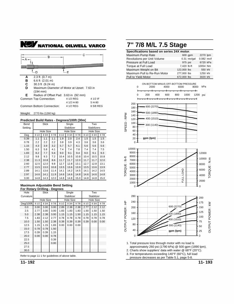
7'' 7/8 M/L 7.5 StageSpecifications based on series 24X motor.Maximum Pump Rate 600 gpm 2270 lpmRevolutions per Unit Volume 0.31 rev/gal 0.082 rev/lPressure at Full Load 975 psi 6720 kPaTorque at Full Load 7,420 lb-ft 10054 NmMaximum Weight on Bit 122,000 lbs 550 kNMaximum Pull to Re-Run Motor 277,000 lbs 1250 kN
A 2.3 ft (0.7 m) Pull to Yield Motor 672,000 lbs 3020 kNB 6.6 ft (2.01 m)C 30.3 ft (9.24 m)D Maximum Diameter of Motor at Upset: 7.63 in
(194 mm)E Radius of Offset Pad: 3.63 in (92 mm)
Common Top Connection: 4 1/2 REG 4 1/2 IF4 1/2 H-90 5 H-90
Common Bottom Connection: 4 1/2 REG 6 5/8 REG
Weight: 2770 lbs (1260 kg)
11- 192 11- 193
Predicted Build Rates - Degrees/100ft (30m)
Setting Stabilizer StabilizersBend
Hole SizeDeg 8 1/2 8 3/4 9 7/8
Hole Size Hole Size8 1/2 8 3/4 9 7/8 8 1/2
For Rotary Drilling - DegreesHole Slick
8 1/2 8 3/4 9 7/8Hole Size
Deg/100ft 8 1/2 8 3/4 9 7/80.0 3.00 3.00 3.00
Slick Single
27.525.0 0.0022.5 0.39
Two
8 3/4 9 7/80.39 1.1 1.1 1.1 1.9 2.0 2.4 1.5 1.5 1.50.78 2.2 2.2 2.2 3.8 3.9 4.3 3.6 3.6 3.61.15 4.3 3.9 3.2 5.7 5.7 6.1 5.6 5.6 5.61.50 6.3 5.8 4.1 7.4 7.4 7.8 7.4 7.4 7.51.83 8.2 7.7 5.6 9.0 9.1 9.4 9.0 9.1 9.32.12 9.8 9.3 7.2 10.4 10.5 10.8 10.4 10.5 10.82.38 11.3 10.8 8.6 11.7 11.7 12.0 11.7 11.7 12.02.60 12.5 12.0 9.8 12.7 12.8 13.1 12.7 12.8 13.12.77 13.5 13.0 10.8 13.5 13.6 13.9 13.5 13.6 13.92.89 14.1 13.6 11.4 14.1 14.2 14.5 14.1 14.2 14.52.97 14.6 14.1 11.9 14.6 14.6 14.8 14.6 14.6 14.83.00 14.8 14.3 12.0 14.8 14.8 15.0 14.8
1.50 1.15
Maximum Adjustable Bend Setting
Single Two
2.382.89 2.38
15.014.8
Curvature Stabilizer Stabilizer
2.77 2.12 2.12
Hole Size Hole Size8 1/2 8 3/4 9 7/8
2.5 2.77 3.00 3.00
7.5 1.83 2.12 2.77 0.78 0.781.50 2.38 0.39 0.39
0.78 0.780.39 0.3910.0 1.50
12.5 1.15 1.15 1.83 0.00 0.00
1.83 1.831.15 1.15
1.83 1.50 1.50 1.505.0 2.38 2.38 3.00 1.15 1.15
0.00 0.000.78 0.78
0.0015.0 0.78 0.78 1.50
2. Charts show suppliers' data with water @ 68°F (20°C). approximately 260 psi (1790 kPa) @ 500 gpm (1890 lpm).1. Total pressure loss through motor with no load is
20.0 0.00 0.00 0.78
30.03. For temperatures exceeding 140°F (60°C), full load pressure decreases as per Table 5.1, page 5-8.Refer to page 11-1 for guidelines of above table.
17.5 0.39 0.39 1.15
300 (1140)
400 (1510)
500 (1890)
600 (2270)
020406080
100120140160180200
SPEE
D :
RPM
gpm (lpm)
kPa0 2000 4000 6000 8000ON-BOTTOM MINUS OFF-BOTTOM PRESSURE
psi0 200 400 600 800 1000 1200
FULL
LO
AD0
100020003000400050006000700080009000
10000
TOR
QU
E : l
b-ft
0
2000
4000
6000
8000
10000
12000
TOR
QU
E : N
.m
300 (1140)
400 (1510)
500 (1890)
600 (2270)
0
40
80
120
160
200
240
280
OU
TPU
T PO
WER
: H
P
0
25
50
75
100
125
150
175
200
OU
TPU
T PO
WER
: kW
gpm (lpm)

7 3/4'' (8") 1/2 H/S 4.0 StageSpecifications based on series 24 motor.Maximum Pump Rate 600 gpm 2270 lpmRevolutions per Unit Volume 0.70 rev/gal 0.185 rev/lPressure at Full Load 520 psi 3580 kPaTorque at Full Load 2,210 lb-ft 2995 NmMaximum Weight on Bit 142,000 lbs 640 kNMaximum Pull to Re-Run Motor 349,000 lbs 1570 kN
A 2.3 ft (0.7 m) Pull to Yield Motor 775,000 lbs 3490 kNB 6.7 ft (2.04 m)C 25.6 ft (7.8 m)D Maximum Diameter of Motor at Upset: 8.63 in
(219 mm)E Radius of Offset Pad: 4.13 in (105 mm)
Common Top Connection: 6 5/8 REG 7 H-90
Common Bottom Connection: 6 5/8 REG
Weight: 2870 lbs (1300 kg)
11- 194 11- 195
3. For temperatures exceeding 140°F (60°C), full load pressure decreases as per Table 5.1, page 5-8.Refer to page 11-1 for guidelines of above table.
Predicted Build Rates - Degrees/100ft (30m)
Setting StabilizerHole Size Hole Size
Slick Single TwoBend
Hole SizeDeg 9 7/8 10 5/8 12 1/4 9 7/8 10 5/8 12 1/4 9 7/8
For Rotary Drilling - DegreesHole Slick
9 7/8 10 5/8 12 1/4Hole Size
Deg/100ft 9 7/8 10 5/8 12 1/40.0 3.00 3.00 3.00
33.030.0 0.3927.0 0.78
10 5/8 12 1/4
Stabilizers
0.39 1.4 1.2 1.2 2.6 2.9 3.6 1.7 1.7 1.80.78 2.4 2.4 2.3 4.6 4.9 5.6 4.1 4.1 4.11.15 4.2 3.5 4.2 6.6 6.9 7.4 6.3 6.3 6.31.50 6.4 4.9 4.4 8.4 8.7 9.2 8.4 8.4 8.41.83 8.4 6.9 5.4 10.2 10.4 10.9 10.2 10.4 10.42.12 10.2 8.7 6.3 11.7 12.0 12.4 11.7 12.0 12.12.38 11.8 10.2 7.1 13.1 13.3 13.7 13.1 13.3 13.72.60 13.2 11.6 8.4 14.3 14.5 14.9 14.3 14.5 14.92.77 14.2 12.6 9.4 15.2 15.4 15.7 15.2 15.4 15.72.89 14.9 13.3 10.1 15.8 16.0 16.3 15.8 16.0 16.3
16.2 16.42.97 15.4 13.8 10.5 16.7 16.2 16.4 16.716.9 16.63.00 15.6 14.0 10.7
1.50 1.15
Maximum Adjustable Bend Setting
Single Two
2.602.38 2.38
16.916.416.4 16.6
Curvature Stabilizer Stabilizer
2.12 2.12 2.12
Hole Size Hole Size9 7/8 10 5/8 12 1/4
3.0 2.77 3.00 3.00
0.39 0.009.0 1.83 2.38 3.00
1.83 2.89 0.39 0.3912.0 1.5015.0 1.15 1.50 2.38 0.00
1.83 1.831.15 1.50
2.12 1.50 1.50 1.50
0.39 0.396.0 2.38 2.77 3.00
1.15 0.390.78 0.78
18.0 0.78 1.15 1.83
1.15 0.78
0.000.00 0.00
2. Charts show suppliers' data with water @ 68°F (20°C). approximately 90 psi (620 kPa) @ 500 gpm (1890 lpm).1. Total pressure loss through motor with no load is
21.0 0.00 0.78 1.5024.0 0.00 1.15
36.0
300 (1140)
400 (1510)
500 (1890)
600 (2270)
050
100150200250300350400450
SPEE
D :
RPM
gpm (lpm)
kPa0 1000 2000 3000 4000 5000ON-BOTTOM MINUS OFF-BOTTOM PRESSURE
psi0 100 200 300 400 500 600 700 800
FULL
LO
AD
0
500
1000
1500
2000
2500
3000
3500
TOR
QU
E : l
b-ft
050010001500200025003000350040004500
TOR
QU
E : N
.m
300 (1140)
400 (1510)
500 (1890)
600 (2270)
0
20
40
60
80
100
120
140
160
180
OU
TPU
T PO
WER
: H
P
0
20
40
60
80
100
120
OU
TPU
T PO
WER
: kW
gpm (lpm)

7 3/4'' (8") 4/5 M/L 3.6 StageSpecifications based on series 24 motor.Maximum Pump Rate 900 gpm 3410 lpmRevolutions per Unit Volume 0.26 rev/gal 0.069 rev/lPressure at Full Load 470 psi 3240 kPaTorque at Full Load 5,160 lb-ft 6992 NmMaximum Weight on Bit 142,000 lbs 640 kNMaximum Pull to Re-Run Motor 349,000 lbs 1570 kN
A 2.3 ft (0.7 m) Pull to Yield Motor 775,000 lbs 3490 kNB 6.7 ft (2.04 m)C 23.4 ft (7.13 m)D Maximum Diameter of Motor at Upset: 8.63 in
(219 mm)E Radius of Offset Pad: 4.13 in (105 mm)
Common Top Connection: 6 5/8 REG 7 H-90
Common Bottom Connection: 6 5/8 REG
Weight: 2620 lbs (1190 kg)
11- 196 11- 197
Predicted Build Rates - Degrees/100ft (30m)
Setting Stabilizer StabilizersBend
Hole SizeDeg 9 7/8 10 5/8 12 1/4
Hole Size Hole Size9 7/8 10 5/8 12 1/4 9 7/8
For Rotary Drilling - DegreesHole Slick
9 7/8 10 5/8 12 1/4Hole Size
Deg/100ft 9 7/8 10 5/8 12 1/40.0 3.00 3.00 3.00
Slick Single
33.030.0 0.3927.0 0.00 0.78
Two
10 5/8 12 1/40.39 1.6 1.3 1.2 2.8 3.2 4.0 1.8 1.8 1.90.78 2.6 2.6 2.5 5.0 5.4 6.1 4.3 4.3 4.31.15 4.6 3.8 4.5 7.1 7.4 8.1 6.7 6.7 6.71.50 6.9 5.3 4.8 9.0 9.4 10.0 9.0 9.0 8.91.83 9.1 7.4 5.8 10.9 11.2 11.8 10.9 11.1 11.12.12 11.0 9.3 6.7 12.5 12.8 13.3 12.5 12.8 12.92.38 12.7 11.0 7.6 14.0 14.2 14.7 14.0 14.2 14.62.60 14.2 12.5 9.0 15.2 15.5 15.9 15.2 15.5 15.92.77 15.3 13.6 10.1 16.2 16.4 16.8 16.2 16.4 16.82.89 16.1 14.3 10.8 16.8 17.1 17.5 16.8 17.1 17.52.97 16.6 14.9 11.3 17.3 17.5 17.9 17.3 17.5 17.93.00 16.8 15.1 11.5 17.5 17.7 18.1 17.7
1.50 0.78
Maximum Adjustable Bend Setting
Single Two
2.602.12 2.38
18.117.5
Curvature Stabilizer Stabilizer
1.83 1.83 1.83
Hole Size Hole Size9 7/8 10 5/8 12 1/4
3.0 2.77 3.00 3.00
9.0 1.83 2.38 3.00 1.15 0.391.83 3.00 0.39 0.39
0.78 0.780.39 0.0012.0 1.50
15.0 1.15 1.50 2.60 0.00 0.00
1.83 1.831.15 1.15
2.12 1.50 1.50 1.506.0 2.38 2.77 3.00 0.78 0.78
0.00 0.000.39 0.39
0.0018.0 0.78 1.15 2.12
0.002. Charts show suppliers' data with water @ 68°F (20°C). approximately 150 psi (1030 kPa) @ 700 gpm (2650 lpm).1. Total pressure loss through motor with no load is
24.0 0.00 0.39 1.50
36.03. For temperatures exceeding 140°F (60°C), full load pressure decreases as per Table 5.1, page 5-8.Refer to page 11-1 for guidelines of above table.
21.0 0.39 0.78 1.83
300 (1140)
500 (1890)
700 (2650)
900 (3410)
0
50
100
150
200
250
SPEE
D :
RPM
gpm (lpm)
kPa0 1000 2000 3000 4000 5000ON-BOTTOM MINUS OFF-BOTTOM PRESSURE
0 200 400 600 800
FULL
LO
AD
0100020003000400050006000700080009000
TOR
QU
E : l
b-ft
0
2000
4000
6000
8000
10000
12000
TOR
QU
E : N
.m
300 (1140)
500 (1890)
700 (2650)
900 (3410)
0
25
50
75
100
125
150
175
200
225
OU
TPU
T PO
WER
: H
P
0
25
50
75
100
125
150
OU
TPU
T PO
WER
: kWgpm (lpm)
psi

7 3/4'' (8") 4/5 M/L 5.3 StageSpecifications based on series 24 motor.Maximum Pump Rate 900 gpm 3410 lpmRevolutions per Unit Volume 0.26 rev/gal 0.069 rev/lPressure at Full Load 690 psi 4750 kPaTorque at Full Load 7,680 lb-ft 10406 NmMaximum Weight on Bit 142,000 lbs 640 kNMaximum Pull to Re-Run Motor 349,000 lbs 1570 kN
A 2.3 ft (0.7 m) Pull to Yield Motor 775,000 lbs 3490 kNB 6.7 ft (2.04 m)C 29 ft (8.84 m)D Maximum Diameter of Motor at Upset: 8.63 in
(219 mm)E Radius of Offset Pad: 4.13 in (105 mm)
Common Top Connection: 6 5/8 REG 7 H-90
Common Bottom Connection: 6 5/8 REG
Weight: 3250 lbs (1470 kg)
11- 198 11- 199
17.5 0.39 0.78 1.83
3. For temperatures exceeding 140°F (60°C), full load pressure decreases as per Table 5.1, page 5-8.Refer to page 11-1 for guidelines of above table.
20.0 0.00 0.39 1.50
30.0 2. Charts show suppliers' data with water @ 68°F (20°C). approximately 190 psi (1310 kPa) @ 700 gpm (2650 lpm).1. Total pressure loss through motor with no load is
0.00
0.0015.0 0.78 1.15 2.120.39 0.00 0.00 0.00
1.15 1.15
0.39 0.390.78 0.78
5.0 2.60 3.00 3.002.12 1.83 1.83 1.832.12 2.12
1.50 1.50
1.83 2.60 0.00 0.0010.0 1.8312.5 1.15
1.15 0.782.12 3.00 0.39 0.78
1.15 1.150.78 0.39
7.5 2.12 2.60 3.00
2.5 3.00 3.00 3.00
Stabilizer Stabilizer
2.12 2.12 2.12
Hole Size Hole Size9 7/8 10 5/8 12 1/4
Curvature
15.415.0
1.83 1.15
Maximum Adjustable Bend Setting
Single Two
2.772.38 2.60
15.0 15.23.00 14.1 12.7 9.7 15.0 15.1 15.4 15.1
14.6 14.92.97 13.9 12.5 9.5 14.8 15.0 15.2 14.8
14.0 14.32.89 13.5 12.0 9.1 14.4 14.6 14.9 14.4
13.2 13.52.77 12.8 11.4 8.5 13.8 14.0 14.3 13.8
12.1 12.52.60 11.9 10.5 7.6 13.0 13.2 13.5 13.0
10.9 11.12.38 10.7 9.2 6.4 11.9 12.1 12.5 11.9
9.5 9.52.12 9.2 7.8 5.7 10.7 10.9 11.2 10.7
7.7 7.71.83 7.6 6.2 4.9 9.3 9.5 9.9 9.3
5.8 5.81.50 5.7 4.4 4.0 7.7 7.9 8.3 7.7
3.7 3.71.15 3.8 3.2 3.7 6.0 6.2 6.7 5.8
1.6 1.60.78 2.2 2.2 2.1 4.1 4.4 4.9 3.7
2.2 2.5 3.1 1.60.39 1.1 1.1 1.1
Two
10 5/8 12 1/4
22.5 0.00 0.78
27.525.0 0.39
Slick Single
0.0 3.00 3.00 3.009 7/8 10 5/8 12 1/4
Hole SizeDeg/100ft 9 7/8 10 5/8 12 1/4
For Rotary Drilling - DegreesHole Slick
Hole Size Hole Size9 7/8 10 5/8 12 1/4 9 7/8
Hole SizeDeg 9 7/8 10 5/8 12 1/4
Predicted Build Rates - Degrees/100ft (30m)
Setting Stabilizer StabilizersBend
300 (1140)
500 (1890)
700 (2650)
900 (3410)
0
50
100
150
200
250
SPEE
D :
RPM
gpm (lpm)
kPa0 1000 2000 3000 4000 5000 6000ON-BOTTOM MINUS OFF-BOTTOM PRESSURE
0 200 400 600 800 1000 psi
FULL
LO
AD
0
2000
4000
6000
8000
10000
12000
TOR
QU
E : l
b-ft
0
2000
4000
6000
8000
10000
12000
14000
16000
TOR
QU
E : N
.m
300 (1140)
500 (1890)
700 (2650)
900 (3410)
0
50
100
150
200
250
300
350
OU
TPU
T PO
WER
: H
P
0
50
100
150
200
250
OU
TPU
T PO
WER
: kWgpm (lpm)

7 3/4'' (8") 5/6 M/L 5.0 StageSpecifications based on series 24 motor.Maximum Pump Rate 900 gpm 3410 lpmRevolutions per Unit Volume 0.29 rev/gal 0.077 rev/lPressure at Full Load 650 psi 4480 kPaTorque at Full Load 5,410 lb-ft 7331 NmMaximum Weight on Bit 142,000 lbs 640 kNMaximum Pull to Re-Run Motor 349,000 lbs 1570 kN
A 2.3 ft (0.7 m) Pull to Yield Motor 775,000 lbs 3490 kNB 6.7 ft (2.04 m)C 24 ft (7.32 m)D Maximum Diameter of Motor at Upset: 8.63 in
(219 mm)E Radius of Offset Pad: 4.13 in (105 mm)
Common Top Connection: 6 5/8 REG 7 H-90
Common Bottom Connection: 6 5/8 REG
Weight: 2690 lbs (1220 kg)
11- 200 11- 201
24.0 0.00 0.39 1.15
36.0
21.0 0.39 0.78 1.50
2. Charts show suppliers' data with water @ 68°F (20°C). approximately 180 psi (1240 kPa) @ 770 gpm (2910 lpm).1. Total pressure loss through motor with no load is
0.000.00 0.00
0.78 0.78
18.0 0.78 1.15 2.12
0.39 0.396.0 2.38 2.77 3.00
1.15 0.390.78 0.78
2.12 1.50 1.50 1.501.83 1.831.15 1.15
1.50 2.60 0.0012.0 1.5015.0 1.15
0.39 0.009.0 1.83 2.38 3.00
1.83 3.00 0.39 0.39
3.0 2.77 3.00 3.00
Stabilizer Stabilizer
1.83 1.83 1.83
Hole Size Hole Size9 7/8 10 5/8 12 1/4
Curvature
17.717.117.1 17.3
1.50 0.78
Maximum Adjustable Bend Setting
Single Two
2.602.12 2.38
17.7 17.33.00 16.4 14.7 11.317.5 17.0 17.2 17.52.97 16.3 14.5 11.1
16.5 16.7 17.117.0 17.2
15.9 16.1 16.52.89 15.7 14.0 10.6 16.5 16.7 17.1
14.9 15.1 15.62.77 15.0 13.3 9.8 15.9 16.1 16.5
13.7 13.9 14.32.60 13.9 12.2 8.8 14.9 15.1 15.6
12.3 12.5 12.72.38 12.4 10.8 7.4 13.7 13.9 14.4
10.7 10.9 10.82.12 10.8 9.1 6.6 12.3 12.5 13.0
8.8 8.8 8.81.83 8.9 7.3 5.7 10.7 11.0 11.5
6.6 6.6 6.61.50 6.7 5.2 4.7 8.8 9.2 9.7
4.3 4.3 4.31.15 4.5 3.7 4.4 6.9 7.2 7.9
1.8 1.8 1.80.78 2.5 2.5 2.4 4.9 5.2 5.9
10 5/8 12 1/4
Stabilizers
0.39 1.5 1.3 1.2 2.7 3.1 3.8
27.0 0.00 0.78
33.030.0 0.39
0.00
0.0 3.00 3.00 3.009 7/8 10 5/8 12 1/4
Hole SizeDeg/100ft 9 7/8 10 5/8 12 1/4
For Rotary Drilling - DegreesHole Slick
9 7/8 10 5/8 12 1/4 9 7/8Deg 9 7/8 10 5/8 12 1/4
Bend
Hole Size Hole Size Hole Size
Slick Single Two
3. For temperatures exceeding 140°F (60°C), full load pressure decreases as per Table 5.1, page 5-8.Refer to page 11-1 for guidelines of above table.
Predicted Build Rates - Degrees/100ft (30m)
Setting Stabilizer 510 (1930)
640 (2420)
770 (2910)
900 (3410)
0
50
100
150
200
250
300
SPEE
D :
RPM
gpm (lpm)
kPa0 1000 2000 3000 4000 5000 6000ON-BOTTOM MINUS OFF-BOTTOM PRESSURE
0 200 400 600 800 1000
FULL
LO
AD
0
1000
2000
3000
4000
5000
6000
7000
8000
9000
TOR
QU
E : l
b-ft
0
2000
4000
6000
8000
10000
12000
TOR
QU
E : N
.m
510 (1930)
640 (2420)
770 (2910)
900 (3410)
0
50
100
150
200
250
300
350
OU
TPU
T PO
WER
: H
P
0
50
100
150
200
250
OU
TPU
T PO
WER
: kW
gpm (lpm)
psi

7 3/4'' (8") 6/7 M/L 4.0 StageSpecifications based on series 24 motor.Maximum Pump Rate 900 gpm 3410 lpmRevolutions per Unit Volume 0.17 rev/gal 0.045 rev/lPressure at Full Load 520 psi 3580 kPaTorque at Full Load 7,680 lb-ft 10406 NmMaximum Weight on Bit 142,000 lbs 640 kNMaximum Pull to Re-Run Motor 349,000 lbs 1570 kN
A 2.3 ft (0.7 m) Pull to Yield Motor 775,000 lbs 3490 kNB 6.7 ft (2.04 m)C 27.2 ft (8.29 m)D Maximum Diameter of Motor at Upset: 8.63 in
(219 mm)E Radius of Offset Pad: 4.13 in (105 mm)
Common Top Connection: 6 5/8 REG 7 H-90
Common Bottom Connection: 6 5/8 REG
Weight: 3050 lbs (1380 kg)
11- 202 11- 203
Predicted Build Rates - Degrees/100ft (30m)
Setting Stabilizer StabilizersBend
Hole SizeDeg 9 7/8 10 5/8 12 1/4
Hole Size Hole Size9 7/8 10 5/8 12 1/4 9 7/8
For Rotary Drilling - DegreesHole Slick
9 7/8 10 5/8 12 1/4Hole Size
Deg/100ft 9 7/8 10 5/8 12 1/40.0 3.00 3.00 3.00
Slick Single
33.030.0 0.0027.0 0.39
Two
10 5/8 12 1/40.39 1.2 1.1 1.1 2.4 2.7 3.3 1.7 1.7 1.70.78 2.3 2.3 2.2 4.4 4.7 5.2 3.9 3.9 3.91.15 4.0 3.3 3.9 6.3 6.5 7.1 6.1 6.1 6.11.50 6.1 4.7 4.2 8.1 8.3 8.8 8.1 8.1 8.11.83 8.0 6.6 5.2 9.7 10.0 10.4 9.7 10.0 10.02.12 9.7 8.3 6.0 11.2 11.4 11.8 11.2 11.4 11.62.38 11.2 9.8 6.7 12.5 12.7 13.1 12.5 12.7 13.12.60 12.5 11.0 8.0 13.7 13.8 14.2 13.7 13.8 14.22.77 13.5 12.0 8.9 14.5 14.7 15.0 14.5 14.7 15.02.89 14.2 12.7 9.6 15.1 15.3 15.6 15.1 15.3 15.62.97 14.7 13.2 10.1 15.5 15.7 16.0 15.5 15.7 16.03.00 14.9 13.4 10.2 15.7 15.9 16.2 15.9
1.50 1.15
Maximum Adjustable Bend Setting
Single Two
2.602.38 2.38
16.215.7
Curvature Stabilizer Stabilizer
2.12 2.12 2.12
Hole Size Hole Size9 7/8 10 5/8 12 1/4
3.0 2.89 3.00 3.00
9.0 1.83 2.38 3.00 1.15 0.391.83 2.77 0.39 0.39
0.78 0.780.39 0.0012.0 1.50
15.0 0.78 1.50 2.38
1.83 1.831.15 1.50
2.12 1.50 1.50 1.506.0 2.38 2.77 3.00 1.15 1.15
0.00 0.000.39 0.39
0.0018.0 0.39 0.78 1.83
2. Charts show suppliers' data with water @ 68°F (20°C). approximately 195 psi (1340 kPa) @ 700 gpm (2650 lpm).1. Total pressure loss through motor with no load is
24.0 0.00 0.78
36.03. For temperatures exceeding 140°F (60°C), full load pressure decreases as per Table 5.1, page 5-8.Refer to page 11-1 for guidelines of above table.
21.0 0.00 0.39 1.50
300 (1140)
500 (1890)
700 (2650)
900 (3410)
020406080
100120140160180
SPEE
D :
RPM
gpm (lpm)
kPa0 1000 2000 3000 4000 5000ON-BOTTOM MINUS OFF-BOTTOM PRESSURE
0 200 400 600 800
FULL
LO
AD
0
2000
4000
6000
8000
10000
12000
TOR
QU
E : l
b-ft
0
2000
4000
6000
8000
10000
12000
14000
16000
TOR
QU
E : N
.m
300 (1140)
500 (1890)
700 (2650)
900 (3410)
0
50
100
150
200
250
300
OU
TPU
T PO
WER
: H
P
0
25
50
75
100
125
150
175
200
OU
TPU
T PO
WER
: kWgpm (lpm)
psi

7 3/4'' (8") 7/8 M/L 2.0 Stage (Air)Specifications based on series 24 motor.Maximum Pump Rate 1,100 gpm 4160 lpmRevolutions per Unit Volume 0.08 rev/gal 0.020 rev/lPressure at Full Load 260 psi 1790 kPaTorque at Full Load 9,040 lb-ft 12249 NmMaximum Weight on Bit 142,000 lbs 640 kNMaximum Pull to Re-Run Motor 349,000 lbs 1570 kN
A 2.3 ft (0.7 m) Pull to Yield Motor 775,000 lbs 3490 kNB 6.7 ft (2.04 m)C 27.4 ft (8.35 m)D Maximum Diameter of Motor at Upset: 8.63 in
(219 mm)E Radius of Offset Pad: 4.13 in (105 mm)
Common Top Connection: 6 5/8 REG 7 H-90
Common Bottom Connection: 6 5/8 REG
Weight: 3070 lbs (1390 kg)
11- 204 11- 205
Predicted Build Rates - Degrees/100ft (30m)
Setting Stabilizer StabilizersBend
Hole SizeDeg 9 7/8 10 5/8 12 1/4
Hole Size Hole Size9 7/8 10 5/8 12 1/4 9 7/8
For Rotary Drilling - DegreesHole Slick
9 7/8 10 5/8 12 1/4Hole Size
Deg/100ft 9 7/8 10 5/8 12 1/40.0 3.00 3.00 3.00
Slick Single
33.030.0 0.0027.0 0.39
Two
10 5/8 12 1/40.39 1.1 1.1 1.1 2.4 2.7 3.3 1.7 1.7 1.70.78 2.3 2.3 2.2 4.4 4.6 5.2 3.9 3.9 3.91.15 4.0 3.3 3.9 6.2 6.5 7.0 6.0 6.0 6.01.50 6.0 4.6 4.2 8.0 8.3 8.7 8.0 8.0 8.01.83 8.0 6.5 5.2 9.7 9.9 10.4 9.7 9.9 9.92.12 9.7 8.2 6.0 11.2 11.4 11.8 11.2 11.4 11.62.38 11.2 9.7 6.7 12.5 12.7 13.1 12.5 12.7 13.12.60 12.5 11.0 7.9 13.6 13.8 14.1 13.6 13.8 14.12.77 13.5 12.0 8.9 14.5 14.6 15.0 14.5 14.6 15.02.89 14.2 12.6 9.6 15.1 15.2 15.5 15.1 15.2 15.52.97 14.6 13.1 10.0 15.5 15.6 15.9 15.5 15.6 15.93.00 14.8 13.3 10.2 15.6 15.8 16.1 15.8
1.50 1.15
Maximum Adjustable Bend Setting
Single Two
2.602.38 2.38
16.115.6
Curvature Stabilizer Stabilizer
2.12 2.12 2.12
Hole Size Hole Size9 7/8 10 5/8 12 1/4
3.0 2.89 3.00 3.00
9.0 1.83 2.38 3.00 0.78 0.391.83 2.77 0.39 0.39
0.78 0.780.39 0.0012.0 1.50
15.0 0.78 1.50 2.38
1.83 1.831.15 1.50
2.12 1.50 1.50 1.506.0 2.38 2.77 3.00 1.15 1.15
0.00 0.000.39 0.39
0.0018.0 0.39 0.78 1.83
2. Charts show suppliers' data with water @ 68°F (20°C). approximately 90 psi (620 kPa) @ 950 gpm (3600 lpm).1. Total pressure loss through motor with no load is
24.0 0.00 0.78
36.03. For temperatures exceeding 140°F (60°C), full load pressure decreases as per Table 5.1, page 5-8.Refer to page 11-1 for guidelines of above table.
21.0 0.00 0.39 1.50
650 (2460)
800 (3030)
950 (3600)
1100 (4160)
0102030405060708090
100
SPEE
D :
RPM
gpm (lpm)
0 500 1000 1500 2000 2500ON-BOTTOM MINUS OFF-BOTTOM PRESSURE
0 100 200 300 400
FULL
LO
AD
0
2000
4000
6000
8000
10000
12000
14000
TOR
QU
E : l
b-ft
0
3000
6000
9000
12000
15000
18000
TOR
QU
E : N
.m
650 (2460)
800 (3030)
950 (3600)
1100 (4160)
020406080
100120140160180200
OU
TPU
T PO
WER
: H
P
0
20
40
60
80
100
120
140
OU
TPU
T PO
WER
: kW
gpm (lpm)
kPa
psi

7 3/4'' (8") 7/8 M/L 3.0 StageSpecifications based on series 24 motor.Maximum Pump Rate 900 gpm 3410 lpmRevolutions per Unit Volume 0.17 rev/gal 0.045 rev/lPressure at Full Load 390 psi 2690 kPaTorque at Full Load 6,220 lb-ft 8428 NmMaximum Weight on Bit 142,000 lbs 640 kNMaximum Pull to Re-Run Motor 349,000 lbs 1570 kN
A 2.3 ft (0.7 m) Pull to Yield Motor 775,000 lbs 3490 kNB 6.7 ft (2.04 m)C 23.4 ft (7.13 m)D Maximum Diameter of Motor at Upset: 8.63 in
(219 mm)E Radius of Offset Pad: 4.13 in (105 mm)
Common Top Connection: 6 5/8 REG 7 H-90
Common Bottom Connection: 6 5/8 REG
Weight: 2620 lbs (1190 kg)
11- 206 11- 207
24.0 0.00 0.39 1.50
36.0
21.0 0.39 0.78 1.83
2. Charts show suppliers' data with water @ 68°F (20°C). approximately 180 psi (1240 kPa) @ 700 gpm (2650 lpm).1. Total pressure loss through motor with no load is
0.000.00 0.00
0.78 0.78
18.0 0.78 1.15 2.12
0.39 0.396.0 2.38 2.77 3.00
1.15 0.390.78 0.78
2.12 1.50 1.50 1.501.83 1.831.15 1.15
1.50 2.60 0.00 0.0012.0 1.5015.0 1.15
0.39 0.009.0 1.83 2.38 3.00
1.83 3.00 0.39 0.39
3.0 2.77 3.00 3.00
Stabilizer Stabilizer
1.83 1.83 1.83
Hole Size Hole Size9 7/8 10 5/8 12 1/4
Curvature
18.117.517.5 17.7
1.50 0.78
Maximum Adjustable Bend Setting
Single Two
2.602.12 2.38
18.1 17.73.00 16.8 15.1 11.517.9 17.3 17.5 17.92.97 16.6 14.9 11.3
16.8 17.1 17.517.3 17.5
16.2 16.4 16.82.89 16.1 14.3 10.8 16.8 17.1 17.5
15.2 15.5 15.92.77 15.3 13.6 10.1 16.2 16.4 16.8
14.0 14.2 14.62.60 14.2 12.5 9.0 15.2 15.5 15.9
12.5 12.8 12.92.38 12.7 11.0 7.6 14.0 14.2 14.7
10.9 11.1 11.12.12 11.0 9.3 6.7 12.5 12.8 13.3
9.0 9.0 8.91.83 9.1 7.4 5.8 10.9 11.2 11.8
6.7 6.7 6.71.50 6.9 5.3 4.8 9.0 9.4 10.0
4.3 4.3 4.31.15 4.6 3.8 4.5 7.1 7.4 8.1
1.8 1.8 1.90.78 2.6 2.6 2.5 5.0 5.4 6.1
10 5/8 12 1/4
Stabilizers
0.39 1.6 1.3 1.2 2.8 3.2 4.0
27.0 0.00 0.78
33.030.0 0.39
0.00
0.0 3.00 3.00 3.009 7/8 10 5/8 12 1/4
Hole SizeDeg/100ft 9 7/8 10 5/8 12 1/4
For Rotary Drilling - DegreesHole Slick
9 7/8 10 5/8 12 1/4 9 7/8Deg 9 7/8 10 5/8 12 1/4
Bend
Hole Size Hole Size Hole Size
Slick Single Two
3. For temperatures exceeding 140°F (60°C), full load pressure decreases as per Table 5.1, page 5-8.Refer to page 11-1 for guidelines of above table.
Predicted Build Rates - Degrees/100ft (30m)
Setting Stabilizer
300 (1140)
500 (1890)
700 (2650)
900 (3410)
0
20
40
60
80
100
120
140
160
SPEE
D :
RPM
gpm (lpm)
0 1000 2000 3000 4000ON-BOTTOM MINUS OFF-BOTTOM PRESSURE
kPa
0 100 200 300 400 500 600
FULL
LO
AD
0
2000
4000
6000
8000
10000
TOR
QU
E : l
b-ft
0
2000
4000
6000
8000
10000
12000
TOR
QU
E : N
.m
300 (1140)
500 (1890)
700 (2650)
900 (3410)
0
25
50
75
100
125
150
175
200
OU
TPU
T PO
WER
: H
P
0
25
50
75
100
125
OU
TPU
T PO
WER
: kW
gpm (lpm)
psi

7 3/4'' (8") 7/8 M/L 4.0 StageSpecifications based on series 24 motor.Maximum Pump Rate 900 gpm 3410 lpmRevolutions per Unit Volume 0.16 rev/gal 0.042 rev/lPressure at Full Load 520 psi 3580 kPaTorque at Full Load 8,660 lb-ft 11734 NmMaximum Weight on Bit 142,000 lbs 640 kNMaximum Pull to Re-Run Motor 349,000 lbs 1570 kN
A 2.3 ft (0.7 m) Pull to Yield Motor 775,000 lbs 3490 kNB 6.7 ft (2.04 m)C 27 ft (8.23 m)D Maximum Diameter of Motor at Upset: 8.63 in
(219 mm)E Radius of Offset Pad: 4.13 in (105 mm)
Common Top Connection: 6 5/8 REG 7 H-90
Common Bottom Connection: 6 5/8 REG
Weight: 3030 lbs (1370 kg)
11- 208 11- 209
24.0 0.00 0.78
36.0
21.0 0.00 0.39 1.50
2. Charts show suppliers' data with water @ 68°F (20°C). approximately 230 psi (1580 kPa) @ 700 gpm (2650 lpm).1. Total pressure loss through motor with no load is
0.000.00 0.00
1.15 1.15
18.0 0.39 0.78 1.83
0.39 0.396.0 2.38 2.77 3.00
1.15 0.390.78 0.78
2.12 1.50 1.50 1.501.83 1.831.15 1.50
1.50 2.3812.0 1.5015.0 1.15
0.39 0.009.0 1.83 2.38 3.00
1.83 2.77 0.39 0.39
3.0 2.77 3.00 3.00
Stabilizer Stabilizer
2.12 2.12 2.12
Hole Size Hole Size9 7/8 10 5/8 12 1/4
Curvature
16.315.815.8 16.0
1.50 1.15
Maximum Adjustable Bend Setting
Single Two
2.602.38 2.38
16.3 16.03.00 15.0 13.4 10.316.1 15.6 15.8 16.12.97 14.8 13.3 10.1
15.2 15.4 15.715.6 15.8
14.6 14.8 15.12.89 14.3 12.8 9.7 15.2 15.4 15.7
13.7 13.9 14.32.77 13.6 12.1 9.0 14.6 14.8 15.1
12.6 12.8 13.22.60 12.6 11.1 8.0 13.7 13.9 14.3
11.3 11.5 11.72.38 11.3 9.8 6.8 12.6 12.8 13.2
9.8 10.0 10.02.12 9.8 8.3 6.0 11.3 11.5 11.9
8.1 8.1 8.11.83 8.1 6.6 5.2 9.8 10.0 10.5
6.1 6.1 6.11.50 6.1 4.7 4.3 8.1 8.4 8.8
3.9 3.9 3.91.15 4.1 3.4 4.0 6.3 6.6 7.1
1.7 1.7 1.70.78 2.3 2.3 2.2 4.4 4.7 5.3
10 5/8 12 1/4
Stabilizers
0.39 1.2 1.1 1.1 2.4 2.7 3.4
27.0 0.39
33.030.0 0.00
0.0 3.00 3.00 3.009 7/8 10 5/8 12 1/4
Hole SizeDeg/100ft 9 7/8 10 5/8 12 1/4
For Rotary Drilling - DegreesHole Slick
9 7/8 10 5/8 12 1/4 9 7/8Deg 9 7/8 10 5/8 12 1/4
Bend
Hole Size Hole Size Hole Size
Slick Single Two
3. For temperatures exceeding 140°F (60°C), full load pressure decreases as per Table 5.1, page 5-8.Refer to page 11-1 for guidelines of above table.
Predicted Build Rates - Degrees/100ft (30m)
Setting Stabilizer
300 (1140)
500 (1890)
700 (2650)
900 (3410)
0
20
40
60
80
100
120
140
160
SPEE
D :
RPM
gpm (lpm)
kPa0 1000 2000 3000 4000 5000 6000ON-BOTTOM MINUS OFF-BOTTOM PRESSURE
0 100 200 300 400 500 600 700 800
FULL
LO
AD
0
2000
4000
6000
8000
10000
12000
14000
TOR
QU
E : l
b-ft
0
2500
5000
7500
10000
12500
15000
17500
TOR
QU
E : N
.m
300 (1140)
500 (1890)
700 (2650)
900 (3410)
0
50
100
150
200
250
OU
TPU
T PO
WER
: H
P
0
25
50
75
100
125
150
175
OU
TPU
T PO
WER
: kW
gpm (lpm)
psi

8" 6/7 M/L 5.0 StageSpecifications based on series 24 motor.Maximum Pump Rate 900 gpm 3410 lpmRevolutions per Unit Volume 0.17 rev/gal 0.045 rev/lPressure at Full Load 650 psi 4480 kPaTorque at Full Load 9,590 lb-ft 12994 NmMaximum Weight on Bit 142,000 lbs 640 kNMaximum Pull to Re-Run Motor 349,000 lbs 1570 kN
A 2.3 ft (0.7 m) Pull to Yield Motor 775,000 lbs 3490 kNB 6.7 ft (2.04 m)C 30.9 ft (9.42 m)D Maximum Diameter of Motor at Upset: 8.63 in
(219 mm)E Radius of Offset Pad: 4.13 in (105 mm)
Common Top Connection: 6 5/8 REG 7 H-90
Common Bottom Connection: 6 5/8 REG
Weight: 3690 lbs (1670 kg)
11- 210 11- 211
20.0 0.00 1.15
30.0
17.5 0.00 0.39 1.50
2. Charts show suppliers' data with water @ 68°F (20°C). approximately 195 psi (1340 kPa) @ 700 gpm (2650 lpm).1. Total pressure loss through motor with no load is
0.00 0.00
0.78 0.78
15.0 0.78 1.15 1.83
0.39 0.395.0 2.38 2.77 3.00
0.78 0.390.39 0.78
1.83 1.50 1.50 1.501.50 1.501.15 1.15
1.50 2.3810.0 1.5012.5 1.15
0.39 0.007.5 1.83 2.38 3.00
1.83 2.77 0.00 0.00
2.5 2.77 3.00 3.00
Stabilizer Stabilizer
1.83 1.83 1.83
Hole Size Hole Size9 7/8 10 5/8 12 1/4
Curvature
14.614.214.2 14.3
1.15 0.78
Maximum Adjustable Bend Setting
Single Two
2.382.12 2.12
14.6 14.33.00 13.5 12.2 9.414.5 14.1 14.2 14.52.97 13.4 12.0 9.2
13.7 13.8 14.114.1 14.2
13.1 13.3 13.52.89 13.0 11.6 8.8 13.7 13.8 14.1
12.3 12.5 12.82.77 12.3 11.0 8.2 13.1 13.3 13.5
11.3 11.5 11.82.60 11.4 10.1 7.3 12.3 12.5 12.8
10.1 10.3 10.62.38 10.3 8.9 6.2 11.3 11.5 11.8
8.7 8.9 9.12.12 8.9 7.6 5.4 10.1 10.3 10.6
7.2 7.4 7.31.83 7.4 6.0 4.7 8.7 8.9 9.3
5.5 5.5 5.51.50 5.6 4.3 3.8 7.2 7.4 7.8
3.6 3.6 3.61.15 3.7 3.0 3.5 5.6 5.8 6.2
1.5 1.5 1.50.78 2.1 2.1 2.0 3.8 4.1 4.5
10 5/8 12 1/4
Stabilizers
0.39 1.0 1.0 1.0 2.0 2.3 2.8
22.5 0.39
27.525.0 0.00
0.0 3.00 3.00 3.009 7/8 10 5/8 12 1/4
Hole SizeDeg/100ft 9 7/8 10 5/8 12 1/4
For Rotary Drilling - DegreesHole Slick
9 7/8 10 5/8 12 1/4 9 7/8Deg 9 7/8 10 5/8 12 1/4
Bend
Hole Size Hole Size Hole Size
Slick Single Two
3. For temperatures exceeding 140°F (60°C), full load pressure decreases as per Table 5.1, page 5-8.Refer to page 11-1 for guidelines of above table.
Predicted Build Rates - Degrees/100ft (30m)
Setting Stabilizer
300 (1140)
500 (1890)
700 (2650)
900 (3410)
020406080
100120140160180
SPEE
D :
RPM
gpm (lpm)
kPa0 1000 2000 3000 4000 5000 6000ON-BOTTOM MINUS OFF-BOTTOM PRESSURE
0 200 400 600 800 1000
FULL
LO
AD
0
2000
4000
6000
8000
10000
12000
14000
16000
TOR
QU
E : l
b-ft
0
2500
5000
7500
10000
12500
15000
17500
20000
TOR
QU
E : N
.m
300 (1140)
500 (1890)
700 (2650)
900 (3410)
0
50
100
150
200
250
300
350
OU
TPU
T PO
WER
: H
P
0
50
100
150
200
250
OU
TPU
T PO
WER
: kW
gpm (lpm)
psi

9 5/8'' 1/2 H/S 4.0 StageSpecifications based on series 17 motor.Maximum Pump Rate 900 gpm 3410 lpmRevolutions per Unit Volume 0.46 rev/gal 0.122 rev/lPressure at Full Load 520 psi 3580 kPaTorque at Full Load 3,410 lb-ft 4621 NmMaximum Weight on Bit 251,000 lbs 1130 kNMaximum Pull to Re-Run Motor 581,000 lbs 2610 kN
A 2.9 ft (0.88 m) Pull to Yield Motor 1,280,000 lbs 5760 kNB 7.5 ft (2.29 m)C 27 ft (8.23 m)D Maximum Diameter of Motor at Upset: 10.75 in
(273 mm)E Radius of Offset Pad: 5 in (127 mm)
Common Top Connection: 6 5/8 REG 7 5/8 REG7 H-90
Common Bottom Connection: 6 5/8 REG 7 5/8 REG
Weight: 4670 lbs (2120 kg)
11- 212 11- 213
24.5 0.78 2.12
3. For temperatures exceeding 140°F (60°C), full load pressure decreases as per Table 5.1, page 5-8.Refer to page 11-1 for guidelines of above table.
28.0 0.00 1.50
42.0 2. Charts show suppliers' data with water @ 68°F (20°C). approximately 170 psi (1170 kPa) @ 770 gpm (2910 lpm).1. Total pressure loss through motor with no load is
0.00
21.0 0.00 1.15 2.60
0.39 0.390.00 0.00
7.0 1.83 3.00 3.002.12 1.15 1.15 1.151.50 1.83
0.78 1.15
1.50 3.0014.0 0.7817.5 0.39
0.78 0.002.12 3.00 0.00
0.39 0.390.00
10.5 1.15 2.77 3.00
3.5 2.38 3.00 3.00
Stabilizer Stabilizer
1.83 1.83 1.83
Hole Size Hole Size12 1/4 14 3/4 17 1/2
Curvature
16.515.6
1.50 0.39
Maximum Adjustable Bend Setting
Single Two
2.772.12 2.38
15.9 16.33.00 14.1 9.8 8.1 15.6 16.1 16.5 16.1
15.6 15.92.97 14.0 9.6 8.0 15.4 15.9 16.4 15.4
15.0 15.22.89 13.5 9.2 7.8 15.0 15.6 16.0 15.0
14.2 14.22.77 12.8 8.5 7.5 14.4 15.0 15.4 14.4
13.1 13.02.60 11.8 7.5 7.0 13.6 14.2 14.7 13.6
11.6 11.52.38 10.5 6.7 6.4 12.5 13.1 13.6 12.5
9.9 9.92.12 9.0 6.0 5.7 11.2 11.9 12.4 11.2
8.0 8.01.83 7.3 5.2 4.9 9.8 10.5 11.1 9.8
6.0 6.01.50 5.3 4.2 4.1 8.1 8.9 9.6 8.1
3.9 3.91.15 3.4 3.3 3.1 6.4 7.2 8.0 6.1
1.7 1.70.78 2.3 2.2 2.1 4.6 5.5 6.3 3.9
2.6 3.6 4.5 1.70.39 1.2 1.1 1.1
Two
14 3/4 17 1/2
31.5 1.15
38.535.0 0.39
Slick Single
0.0 2.89 3.00 3.0012 1/4 14 3/4 17 1/2
Hole SizeDeg/100ft 12 1/4 14 3/4 17 1/2
For Rotary Drilling - DegreesHole Slick
Hole Size Hole Size12 1/4 14 3/4 17 1/2 12 1/4
Hole SizeDeg 12 1/4 14 3/4 17 1/2
Predicted Build Rates - Degrees/100ft (30m)
Setting Stabilizer StabilizersBend 510 (1930)
640 (2420)
770 (2910)
900 (3410)
050
100150200250300350400450
SPEE
D :
RPM
gpm (lpm)
kPa0 1000 2000 3000 4000 5000ON-BOTTOM MINUS OFF-BOTTOM PRESSURE
0 200 400 600 800
FULL
LO
AD
0
1000
2000
3000
4000
5000
6000
TOR
QU
E : l
b-ft
0
1000
2000
3000
4000
5000
6000
7000
8000
TOR
QU
E : N
.m
510 (1930)
640 (2420)
770 (2910)
900 (3410)
0255075
100125150175200225250
OU
TPU
T PO
WER
: H
P
0
25
50
75
100
125
150
175
OU
TPU
T PO
WER
: kW
gpm (lpm)
psi

9 5/8'' 2/3 M/L 7.5 StageSpecifications based on series 17 motor.Maximum Pump Rate 1,200 gpm 4540 lpmRevolutions per Unit Volume 0.49 rev/gal 0.129 rev/lPressure at Full Load 975 psi 6720 kPaTorque at Full Load 5,490 lb-ft 7439 NmMaximum Weight on Bit 251,000 lbs 1130 kNMaximum Pull to Re-Run Motor 581,000 lbs 2610 kN
A 2.9 ft (0.88 m) Pull to Yield Motor 1,280,000 lbs 5760 kNB 7.5 ft (2.29 m)C 28.56 ft (8.71 m)D Maximum Diameter of Motor at Upset: 10.75 in
(273 mm)E Radius of Offset Pad: 5 in (127 mm)
Common Top Connection: 6 5/8 REG 7 5/8 REG7 H-90
Common Bottom Connection: 6 5/8 REG 7 5/8 REG
Weight: 4930 lbs (2240 kg)
11- 214 11- 215
Predicted Build Rates - Degrees/100ft (30m)
Setting Stabilizer StabilizersBend
Hole SizeDeg 12 1/4 14 3/4 17 1/2
Hole Size Hole Size12 1/4 14 3/4 17 1/2 12 1/4
For Rotary Drilling - DegreesHole Slick
12 1/4 14 3/4 17 1/2Hole Size
Deg/100ft 12 1/4 14 3/4 17 1/20.0 3.00 3.00 3.00
Slick Single
38.535.0 0.0031.5 0.78
Two
14 3/4 17 1/20.39 1.1 1.1 1.0 2.5 3.3 4.1 1.6 1.6 1.70.78 2.2 2.1 2.0 4.3 5.1 5.9 3.8 3.8 3.81.15 3.2 3.1 3.0 6.1 6.8 7.5 5.8 5.8 5.81.50 5.1 4.0 3.9 7.8 8.4 9.1 7.7 7.7 7.71.83 6.9 4.9 4.7 9.3 10.0 10.5 9.3 9.5 9.52.12 8.5 5.7 5.5 10.7 11.3 11.8 10.7 11.1 11.02.38 10.0 6.4 6.1 11.9 12.5 13.0 11.9 12.5 12.42.60 11.2 7.2 6.7 13.0 13.5 13.9 13.0 13.5 13.62.77 12.1 8.1 7.1 13.8 14.3 14.7 13.8 14.3 14.62.89 12.8 8.7 7.5 14.4 14.8 15.2 14.4 14.8 15.22.97 13.3 9.2 7.7 14.7 15.2 15.6 14.7 15.2 15.63.00 13.4 9.3 7.7 14.9 15.3 15.7 15.3
1.50 0.78
Maximum Adjustable Bend Setting
Single Two
2.772.12 2.38
15.714.9
Curvature Stabilizer Stabilizer
1.83 1.83 1.83
Hole Size Hole Size12 1/4 14 3/4 17 1/2
3.5 2.38 3.00 3.00
10.5 1.15 2.60 3.00 0.78 0.002.12 3.00 0.00
0.39 0.390.0014.0 0.78
17.5 0.39 1.50 3.00
1.50 1.830.78 1.15
2.12 1.15 1.15 1.157.0 1.83 3.00 3.00 0.39 0.39
0.00 0.00
21.0 0.78 2.38
2. Charts show suppliers' data with water @ 68°F (20°C). approximately 170 psi (1170 kPa) @ 1000 gpm (3790 lpm).1. Total pressure loss through motor with no load is
28.0 0.00 1.15
42.03. For temperatures exceeding 140°F (60°C), full load pressure decreases as per Table 5.1, page 5-8.Refer to page 11-1 for guidelines of above table.
24.5 0.39 1.83
600 (2270)
800 (3030)
1000 (3790)
1200 (4540)
0
100
200
300
400
500
600
700
SPEE
D :
RPM
gpm (lpm)
kPa0 2000 4000 6000 8000ON-BOTTOM MINUS OFF-BOTTOM PRESSURE
psi0 200 400 600 800 1000 1200
FULL
LO
AD0
1000
2000
3000
4000
5000
6000
7000
TOR
QU
E : l
b-ft
0100020003000400050006000700080009000
TOR
QU
E : N
.m
600 (2270)
800 (3030)
1000 (3790)
1200 (4540)
0
100
200
300
400
500
600
700
OU
TPU
T PO
WER
: H
P
050100150200250300350400450500
OU
TPU
T PO
WER
: kW
gpm (lpm)

9 5/8'' 3/4 M/L 4.5 StageSpecifications based on series 17 motor.Maximum Pump Rate 1,200 gpm 4540 lpmRevolutions per Unit Volume 0.23 rev/gal 0.061 rev/lPressure at Full Load 590 psi 4070 kPaTorque at Full Load 7,450 lb-ft 10095 NmMaximum Weight on Bit 251,000 lbs 1130 kNMaximum Pull to Re-Run Motor 581,000 lbs 2610 kN
A 2.9 ft (0.88 m) Pull to Yield Motor 1,280,000 lbs 5760 kNB 7.5 ft (2.29 m)C 25.9 ft (7.89 m)D Maximum Diameter of Motor at Upset: 10.75 in
(273 mm)E Radius of Offset Pad: 5 in (127 mm)
Common Top Connection: 6 5/8 REG 7 5/8 REG7 H-90
Common Bottom Connection: 6 5/8 REG 7 5/8 REG
Weight: 4480 lbs (2030 kg)
11- 216 11- 217
3. For temperatures exceeding 140°F (60°C), full load pressure decreases as per Table 5.1, page 5-8.Refer to page 11-1 for guidelines of above table.
Predicted Build Rates - Degrees/100ft (30m)
Setting StabilizerHole Size Hole Size
Slick Single TwoBend
Hole SizeDeg 12 1/4 14 3/4 17 1/2 12 1/4 14 3/4 17 1/2 12 1/4
For Rotary Drilling - DegreesHole Slick
12 1/4 14 3/4 17 1/2Hole Size
Deg/100ft 12 1/4 14 3/4 17 1/20.0 2.89 3.00 3.00
38.535.0 0.78
0.39
31.5 1.15
14 3/4 17 1/2
Stabilizers
0.39 1.2 1.1 1.1 2.7 3.7 4.7 1.7 1.7 1.80.78 2.4 2.3 2.2 4.7 5.7 6.5 4.0 4.0 4.01.15 3.5 3.3 3.2 6.6 7.5 8.2 6.2 6.2 6.21.50 5.5 4.4 4.2 8.4 9.2 9.9 8.3 8.2 8.21.83 7.5 5.3 5.1 10.0 10.8 11.4 10.0 10.2 10.12.12 9.2 6.1 5.9 11.5 12.2 12.8 11.5 11.9 11.82.38 10.8 6.9 6.6 12.8 13.5 14.0 12.8 13.4 13.32.60 12.1 7.7 7.2 13.9 14.5 15.1 13.9 14.5 14.62.77 13.2 8.7 7.7 14.8 15.4 15.9 14.8 15.4 15.62.89 13.9 9.4 8.0 15.4 16.0 16.4 15.4 16.0 16.2
15.8 16.42.97 14.4 9.9 8.2 16.8 15.8 16.4 16.716.9 16.53.00 14.5 10.1 8.3
1.50 0.39
Maximum Adjustable Bend Setting
Single Two
2.772.12 2.38
16.916.016.0 16.5
Curvature Stabilizer Stabilizer
1.83 1.83 1.83
Hole Size Hole Size12 1/4 14 3/4 17 1/2
3.5 2.38 3.00 3.00
0.3910.5 1.50 2.77 3.00
2.12 3.00 0.0014.0 0.7817.5 0.39 1.83 3.00
1.50 1.830.78 1.15
2.12 1.15 1.15 1.15
0.00 0.007.0 1.83 3.00 3.00
0.78 0.000.39 0.39
21.0 0.00 1.15 2.77
0.39 0.39
2. Charts show suppliers' data with water @ 68°F (20°C). approximately 160 psi (1100 kPa) @ 1000 gpm (3790 lpm).1. Total pressure loss through motor with no load is
24.5 0.78 2.1228.0 0.39 1.83
42.0
600 (2270)
800 (3030)
1000 (3790)
1200 (4540)
0
50
100
150
200
250
300
SPEE
D :
RPM
gpm (lpm)
kPa0 1000 2000 3000 4000 5000ON-BOTTOM MINUS OFF-BOTTOM PRESSURE
0 200 400 600 800
FULL
LO
AD
0
2000
4000
6000
8000
10000
12000
TOR
QU
E : l
b-ft
0
2000
4000
6000
8000
10000
12000
14000
16000
TOR
QU
E : N
.m
600 (2270)
800 (3030)
1000 (3790)
1200 (4540)
0
50
100
150
200
250
300
350
OU
TPU
T PO
WER
: H
P
0
50
100
150
200
250
OU
TPU
T PO
WER
: kW
gpm (lpm)
psi

9 5/8'' 3/4 M/L 6.0 StageSpecifications based on series 17 motor.Maximum Pump Rate 1,200 gpm 4540 lpmRevolutions per Unit Volume 0.22 rev/gal 0.058 rev/lPressure at Full Load 780 psi 5370 kPaTorque at Full Load 10,170 lb-ft 13780 NmMaximum Weight on Bit 251,000 lbs 1130 kNMaximum Pull to Re-Run Motor 581,000 lbs 2610 kN
A 2.9 ft (0.88 m) Pull to Yield Motor 1,280,000 lbs 5760 kNB 7.5 ft (2.29 m)C 30.3 ft (9.24 m)D Maximum Diameter of Motor at Upset: 10.75 in
(273 mm)E Radius of Offset Pad: 5 in (127 mm)
Common Top Connection: 6 5/8 REG 7 5/8 REG7 H-90
Common Bottom Connection: 6 5/8 REG 7 5/8 REG
Weight: 5240 lbs (2370 kg)
11- 218 11- 219
21.0 0.78 2.12
3. For temperatures exceeding 140°F (60°C), full load pressure decreases as per Table 5.1, page 5-8.Refer to page 11-1 for guidelines of above table.
24.0 0.39 1.50
36.0 2. Charts show suppliers' data with water @ 68°F (20°C). approximately 180 psi (1240 kPa) @ 1000 gpm (3790 lpm).1. Total pressure loss through motor with no load is
0.00
18.0 0.00 1.15 2.60
0.78 0.780.00 0.00
6.0 2.12 3.00 3.002.12 1.50 1.50 1.151.83 1.83
1.15 1.15
1.83 3.0012.0 1.1515.0 0.39
0.78 0.392.38 3.00 0.00 0.00
0.39 0.780.39
9.0 1.50 2.77 3.00
3.0 2.60 3.00 3.00
Stabilizer Stabilizer
2.12 1.83 1.83
Hole Size Hole Size12 1/4 14 3/4 17 1/2
Curvature
15.014.3
1.50 0.78
Maximum Adjustable Bend Setting
Single Two
2.772.38 2.60
14.6 14.93.00 12.8 8.9 7.4 14.3 14.7 15.0 14.7
14.2 14.62.97 12.7 8.8 7.3 14.2 14.6 14.9 14.2
13.7 14.02.89 12.2 8.3 7.1 13.8 14.2 14.6 13.8
12.9 13.12.77 11.6 7.7 6.9 13.2 13.7 14.1 13.2
11.9 12.02.60 10.7 6.9 6.4 12.5 12.9 13.3 12.5
10.7 10.62.38 9.5 6.1 5.9 11.5 11.9 12.4 11.5
9.1 9.12.12 8.1 5.5 5.2 10.3 10.8 11.3 10.3
7.4 7.41.83 6.6 4.7 4.5 8.9 9.5 10.0 8.9
5.6 5.61.50 4.8 3.9 3.7 7.4 8.0 8.6 7.4
3.6 3.61.15 3.1 3.0 2.8 5.8 6.5 7.1 5.6
1.6 1.60.78 2.1 2.0 1.9 4.1 4.8 5.5 3.6
2.3 3.1 3.9 1.60.39 1.0 1.0 1.0
Two
14 3/4 17 1/2
27.0 0.00 1.15
33.030.0 0.78
Slick Single
0.0 3.00 3.00 3.0012 1/4 14 3/4 17 1/2
Hole SizeDeg/100ft 12 1/4 14 3/4 17 1/2
For Rotary Drilling - DegreesHole Slick
Hole Size Hole Size12 1/4 14 3/4 17 1/2 12 1/4
Hole SizeDeg 12 1/4 14 3/4 17 1/2
Predicted Build Rates - Degrees/100ft (30m)
Setting Stabilizer StabilizersBend
600 (2270)
800 (3030)
1000 (3790)
1200 (4540)
0
50
100
150
200
250
300
SPEE
D :
RPM
gpm (lpm)
kPa0 1000 2000 3000 4000 5000 6000ON-BOTTOM MINUS OFF-BOTTOM PRESSURE
0 200 400 600 800 1000
FULL
LO
AD
0
2000
4000
6000
8000
10000
12000
14000
TOR
QU
E : l
b-ft
0
2500
5000
7500
10000
12500
15000
17500
TOR
QU
E : N
.m
600 (2270)
800 (3030)
1000 (3790)
1200 (4540)
050
100150200250300350400450500
OU
TPU
T PO
WER
: H
P
0
50
100
150
200
250
300
350
OU
TPU
T PO
WER
: kW
gpm (lpm)
psi

9 5/8'' 5/6 M/L 3.0 StageSpecifications based on series 17 motor.Maximum Pump Rate 1,200 gpm 4540 lpmRevolutions per Unit Volume 0.11 rev/gal 0.029 rev/lPressure at Full Load 390 psi 2690 kPaTorque at Full Load 9,450 lb-ft 12805 NmMaximum Weight on Bit 251,000 lbs 1130 kNMaximum Pull to Re-Run Motor 581,000 lbs 2610 kN
A 2.9 ft (0.88 m) Pull to Yield Motor 1,280,000 lbs 5760 kNB 7.5 ft (2.29 m)C 25.9 ft (7.89 m)D Maximum Diameter of Motor at Upset: 10.75 in
(273 mm)E Radius of Offset Pad: 5 in (127 mm)
Common Top Connection: 6 5/8 REG 7 5/8 REG7 H-90
Common Bottom Connection: 6 5/8 REG 7 5/8 REG
Weight: 4480 lbs (2030 kg)
11- 220 11- 221
3. For temperatures exceeding 140°F (60°C), full load pressure decreases as per Table 5.1, page 5-8.Refer to page 11-1 for guidelines of above table.
Predicted Build Rates - Degrees/100ft (30m)
Setting StabilizerHole Size Hole Size
Slick Single TwoBend
Hole SizeDeg 12 1/4 14 3/4 17 1/2 12 1/4 14 3/4 17 1/2 12 1/4
For Rotary Drilling - DegreesHole Slick
12 1/4 14 3/4 17 1/2Hole Size
Deg/100ft 12 1/4 14 3/4 17 1/20.0 2.89 3.00 3.00
38.535.0 0.78
0.39
31.5 1.15
14 3/4 17 1/2
Stabilizers
0.39 1.2 1.1 1.1 2.7 3.7 4.7 1.7 1.7 1.80.78 2.4 2.3 2.2 4.7 5.7 6.5 4.0 4.0 4.01.15 3.5 3.3 3.2 6.6 7.5 8.2 6.2 6.2 6.21.50 5.5 4.4 4.2 8.4 9.2 9.9 8.3 8.2 8.21.83 7.5 5.3 5.1 10.0 10.8 11.4 10.0 10.2 10.12.12 9.2 6.1 5.9 11.5 12.2 12.8 11.5 11.9 11.82.38 10.8 6.9 6.6 12.8 13.5 14.0 12.8 13.4 13.32.60 12.1 7.7 7.2 13.9 14.5 15.1 13.9 14.5 14.62.77 13.2 8.7 7.7 14.8 15.4 15.9 14.8 15.4 15.62.89 13.9 9.4 8.0 15.4 16.0 16.4 15.4 16.0 16.2
15.8 16.42.97 14.4 9.9 8.2 16.8 15.8 16.4 16.716.9 16.53.00 14.5 10.1 8.3
1.50 0.39
Maximum Adjustable Bend Setting
Single Two
2.772.12 2.38
16.916.016.0 16.5
Curvature Stabilizer Stabilizer
1.83 1.83 1.83
Hole Size Hole Size12 1/4 14 3/4 17 1/2
3.5 2.38 3.00 3.00
0.3910.5 1.50 2.77 3.00
2.12 3.00 0.0014.0 0.7817.5 0.39 1.83 3.00
1.50 1.830.78 1.15
2.12 1.15 1.15 1.15
0.00 0.007.0 1.83 3.00 3.00
0.78 0.000.39 0.39
21.0 0.00 1.15 2.77
0.39 0.39
2. Charts show suppliers' data with water @ 68°F (20°C). approximately 160 psi (1100 kPa) @ 1000 gpm (3790 lpm).1. Total pressure loss through motor with no load is
24.5 0.78 2.1228.0 0.39 1.83
42.0
600 (2270)
800 (3030)
1000 (3790)
1200 (4540)
0
20
40
60
80
100
120
140
SPEE
D :
RPM
gpm (lpm)
0 1000 2000 3000 4000ON-BOTTOM MINUS OFF-BOTTOM PRESSURE
0 100 200 300 400 500 600
FULL
LO
AD
0
2000
4000
6000
8000
10000
12000
14000
16000
TOR
QU
E : l
b-ft
0
2500
5000
7500
10000
12500
15000
17500
20000
TOR
QU
E : N
.m
600 (2270)
800 (3030)
1000 (3790)
1200 (4540)
0255075
100125150175200225250
OU
TPU
T PO
WER
: H
P
0
25
50
75
100
125
150
175
OU
TPU
T PO
WER
: kW
gpm (lpm)
kPa
psi

9 5/8'' 5/6 M/L 4.0 StageSpecifications based on series 17 motor.Maximum Pump Rate 1,200 gpm 4540 lpmRevolutions per Unit Volume 0.12 rev/gal 0.032 rev/lPressure at Full Load 520 psi 3580 kPaTorque at Full Load 12,580 lb-ft 17046 NmMaximum Weight on Bit 251,000 lbs 1130 kNMaximum Pull to Re-Run Motor 581,000 lbs 2610 kN
A 2.9 ft (0.88 m) Pull to Yield Motor 1,280,000 lbs 5760 kNB 7.5 ft (2.29 m)C 30.3 ft (9.24 m)D Maximum Diameter of Motor at Upset: 10.75 in
(273 mm)E Radius of Offset Pad: 5 in (127 mm)
Common Top Connection: 6 5/8 REG 7 5/8 REG7 H-90
Common Bottom Connection: 6 5/8 REG 7 5/8 REG
Weight: 5240 lbs (2370 kg)
11- 222 11- 223
3. For temperatures exceeding 140°F (60°C), full load pressure decreases as per Table 5.1, page 5-8.Refer to page 11-1 for guidelines of above table.
Predicted Build Rates - Degrees/100ft (30m)
Setting StabilizerHole Size Hole Size
Slick Single TwoBend
Hole SizeDeg 12 1/4 14 3/4 17 1/2 12 1/4 14 3/4 17 1/2 12 1/4
For Rotary Drilling - DegreesHole Slick
12 1/4 14 3/4 17 1/2Hole Size
Deg/100ft 12 1/4 14 3/4 17 1/20.0 3.00 3.00 3.00
33.030.0 0.78
0.00
27.0 0.00 1.15
14 3/4 17 1/2
Stabilizers
0.39 1.0 1.0 1.0 2.3 3.1 3.9 1.6 1.6 1.60.78 2.1 2.0 1.9 4.1 4.8 5.5 3.6 3.6 3.61.15 3.1 3.0 2.8 5.8 6.5 7.1 5.6 5.6 5.61.50 4.8 3.9 3.7 7.4 8.0 8.6 7.4 7.4 7.41.83 6.6 4.7 4.5 8.9 9.5 10.0 8.9 9.1 9.12.12 8.1 5.5 5.2 10.3 10.8 11.3 10.3 10.7 10.62.38 9.5 6.1 5.9 11.5 11.9 12.4 11.5 11.9 12.02.60 10.7 6.9 6.4 12.5 12.9 13.3 12.5 12.9 13.12.77 11.6 7.7 6.9 13.2 13.7 14.1 13.2 13.7 14.02.89 12.2 8.3 7.1 13.8 14.2 14.6 13.8 14.2 14.6
14.2 14.62.97 12.7 8.8 7.3 14.9 14.2 14.6 14.915.0 14.73.00 12.8 8.9 7.4
1.50 0.78
Maximum Adjustable Bend Setting
Single Two
2.772.38 2.60
15.014.314.3 14.7
Curvature Stabilizer Stabilizer
2.12 1.83 1.83
Hole Size Hole Size12 1/4 14 3/4 17 1/2
3.0 2.60 3.00 3.00
0.399.0 1.50 2.77 3.00
2.38 3.00 0.00 0.0012.0 1.1515.0 0.39 1.83 3.00
1.83 1.831.15 1.15
2.12 1.50 1.50 1.15
0.00 0.006.0 2.12 3.00 3.00
0.78 0.390.39 0.78
18.0 0.00 1.15 2.60
0.78 0.78
2. Charts show suppliers' data with water @ 68°F (20°C). approximately 230 psi (1580 kPa) @ 1000 gpm (3790 lpm).1. Total pressure loss through motor with no load is
21.0 0.78 2.1224.0 0.39 1.50
36.0
600 (2270)
800 (3030)
1000 (3790)
1200 (4540)
0
20
40
60
80
100
120
140
SPEE
D :
RPM
gpm (lpm)
0 1000 2000 3000 4000 5000ON-BOTTOM MINUS OFF-BOTTOM PRESSURE
0 200 400 600 800
FULL
LO
AD
0
2500
5000
7500
10000
12500
15000
17500
20000
TOR
QU
E : l
b-ft
0
5000
10000
15000
20000
25000
TOR
QU
E : N
.m
600 (2270)
800 (3030)
1000 (3790)
1200 (4540)
0
50
100
150
200
250
300
350
OU
TPU
T PO
WER
: H
P
0
50
100
150
200
250
OU
TPU
T PO
WER
: kW
gpm (lpm)
kPa
psi

9 5/8'' 6/7 M/L 5.0 StageSpecifications based on series 17 motor.Maximum Pump Rate 1,200 gpm 4540 lpmRevolutions per Unit Volume 0.13 rev/gal 0.034 rev/lPressure at Full Load 650 psi 4480 kPaTorque at Full Load 12,040 lb-ft 16314 NmMaximum Weight on Bit 251,000 lbs 1130 kNMaximum Pull to Re-Run Motor 581,000 lbs 2610 kN
A 2.9 ft (0.88 m) Pull to Yield Motor 1,280,000 lbs 5760 kNB 7.5 ft (2.29 m)C 28.4 ft (8.66 m)D Maximum Diameter of Motor at Upset: 10.75 in
(273 mm)E Radius of Offset Pad: 5 in (127 mm)
Common Top Connection: 6 5/8 REG 7 5/8 REG7 H-90
Common Bottom Connection: 6 5/8 REG 7 5/8 REG
Weight: 4910 lbs (2230 kg)
11- 224 11- 225
24.5 0.39 1.83
3. For temperatures exceeding 140°F (60°C), full load pressure decreases as per Table 5.1, page 5-8.Refer to page 11-1 for guidelines of above table.
28.0 0.00 1.15
42.0 2. Charts show suppliers' data with water @ 68°F (20°C). approximately 170 psi (1170 kPa) @ 1000 gpm (3790 lpm).1. Total pressure loss through motor with no load is
21.0 0.78 2.38
0.39 0.390.00 0.00
7.0 1.83 3.00 3.002.12 1.15 1.15 1.151.50 1.83
0.78 1.15
1.50 3.0014.0 0.7817.5 0.39
0.78 0.002.12 3.00 0.00
0.39 0.390.00
10.5 1.15 2.60 3.00
3.5 2.38 3.00 3.00
Stabilizer Stabilizer
1.83 1.83 1.83
Hole Size Hole Size12 1/4 14 3/4 17 1/2
Curvature
15.714.9
1.50 0.78
Maximum Adjustable Bend Setting
Single Two
2.772.12 2.38
15.2 15.63.00 13.4 9.3 7.7 14.9 15.3 15.7 15.3
14.8 15.22.97 13.3 9.2 7.7 14.7 15.2 15.6 14.7
14.3 14.62.89 12.8 8.7 7.5 14.4 14.8 15.2 14.4
13.5 13.62.77 12.1 8.1 7.1 13.8 14.3 14.7 13.8
12.5 12.42.60 11.2 7.2 6.7 13.0 13.5 13.9 13.0
11.1 11.02.38 10.0 6.4 6.1 11.9 12.5 13.0 11.9
9.5 9.52.12 8.5 5.7 5.5 10.7 11.3 11.8 10.7
7.7 7.71.83 6.9 4.9 4.7 9.3 10.0 10.5 9.3
5.8 5.81.50 5.1 4.0 3.9 7.8 8.4 9.1 7.7
3.8 3.81.15 3.2 3.1 3.0 6.1 6.8 7.5 5.8
1.6 1.70.78 2.2 2.1 2.0 4.3 5.1 5.9 3.8
2.5 3.3 4.1 1.60.39 1.1 1.1 1.0
Two
14 3/4 17 1/2
31.5 0.78
38.535.0 0.00
Slick Single
0.0 3.00 3.00 3.0012 1/4 14 3/4 17 1/2
Hole SizeDeg/100ft 12 1/4 14 3/4 17 1/2
For Rotary Drilling - DegreesHole Slick
Hole Size Hole Size12 1/4 14 3/4 17 1/2 12 1/4
Hole SizeDeg 12 1/4 14 3/4 17 1/2
Predicted Build Rates - Degrees/100ft (30m)
Setting Stabilizer StabilizersBend 600 (2270)
800 (3030)
1000 (3790)
1200 (4540)
0
20
40
60
80
100
120
140
160
SPEE
D :
RPM
gpm (lpm)
0 1000 2000 3000 4000 5000ON-BOTTOM MINUS OFF-BOTTOM PRESSURE
0 200 400 600 800
FULL
LO
AD
0
2500
5000
7500
10000
12500
15000
TOR
QU
E : l
b-ft
0
4000
8000
12000
16000
20000
TOR
QU
E : N
.m
600 (2270)
800 (3030)
1000 (3790)
1200 (4540)
0
50
100
150
200
250
300
350
OU
TPU
T PO
WER
: H
P
0
50
100
150
200
250
OU
TPU
T PO
WER
: kW
gpm (lpm)
psi
kPa

9 5/8'' 6/7 M/L 6.0 StageSpecifications based on series 17 motor.Maximum Pump Rate 1,200 gpm 4540 lpmRevolutions per Unit Volume 0.13 rev/gal 0.034 rev/lPressure at Full Load 780 psi 5370 kPaTorque at Full Load 14,450 lb-ft 19580 NmMaximum Weight on Bit 251,000 lbs 1130 kNMaximum Pull to Re-Run Motor 581,000 lbs 2610 kN
A 2.9 ft (0.88 m) Pull to Yield Motor 1,280,000 lbs 5760 kNB 7.5 ft (2.29 m)C 32.06 ft (9.77 m)D Maximum Diameter of Motor at Upset: 10.75 in
(273 mm)E Radius of Offset Pad: 5 in (127 mm)
Common Top Connection: 6 5/8 REG 7 5/8 REG7 H-90
Common Bottom Connection: 6 5/8 REG 7 5/8 REG
Weight: 5540 lbs (2510 kg)
11- 226 11- 227
Predicted Build Rates - Degrees/100ft (30m)
Setting Stabilizer StabilizersBend
Hole SizeDeg 12 1/4 14 3/4 17 1/2
Hole Size Hole Size12 1/4 14 3/4 17 1/2 12 1/4
For Rotary Drilling - DegreesHole Slick
12 1/4 14 3/4 17 1/2Hole Size
Deg/100ft 12 1/4 14 3/4 17 1/20.0 3.00 3.00 3.00
Slick Single
33.030.0 0.3927.0 0.78
Two
14 3/4 17 1/20.39 1.0 1.0 0.9 2.2 2.9 3.6 1.5 1.5 1.50.78 2.0 1.9 1.8 3.9 4.6 5.2 3.5 3.5 3.51.15 2.9 2.8 2.7 5.5 6.2 6.7 5.3 5.3 5.31.50 4.6 3.7 3.6 7.1 7.6 8.2 7.1 7.1 7.11.83 6.3 4.5 4.3 8.5 9.1 9.5 8.5 8.8 8.72.12 7.7 5.2 5.0 9.8 10.3 10.7 9.8 10.2 10.22.38 9.1 5.9 5.6 11.0 11.4 11.8 11.0 11.4 11.52.60 10.2 6.5 6.2 11.9 12.3 12.7 11.9 12.3 12.62.77 11.0 7.4 6.6 12.7 13.1 13.4 12.7 13.1 13.42.89 11.7 8.0 6.8 13.2 13.6 13.9 13.2 13.6 13.92.97 12.1 8.4 7.0 13.6 13.9 14.2 13.6 13.9 14.23.00 12.2 8.5 7.1 13.7 14.1 14.4 14.1
1.50 0.78
Maximum Adjustable Bend Setting
Single Two
2.772.38 2.60
14.413.7
Curvature Stabilizer Stabilizer
2.12 2.12 1.83
Hole Size Hole Size12 1/4 14 3/4 17 1/2
3.0 2.60 3.00 3.00
9.0 1.50 2.77 3.00 0.78 0.392.12 3.00 0.00 0.00
0.39 0.780.3912.0 1.15
15.0 0.39 1.83 3.00
1.83 1.831.15 1.15
2.12 1.50 1.50 1.506.0 2.12 3.00 3.00 0.78 0.78
0.00 0.00
18.0 0.00 1.15 2.38
0.002. Charts show suppliers' data with water @ 68°F (20°C). approximately 170 psi (1170 kPa) @ 1000 gpm (3790 lpm).1. Total pressure loss through motor with no load is
24.0 0.00 1.50
36.03. For temperatures exceeding 140°F (60°C), full load pressure decreases as per Table 5.1, page 5-8.Refer to page 11-1 for guidelines of above table.
21.0 0.78 1.83
600 (2270)
800 (3030)
1000 (3790)
1200 (4540)
0
20
40
60
80
100
120
140
160
SPEE
D :
RPM
gpm (lpm)
kPa0 1000 2000 3000 4000 5000 6000ON-BOTTOM MINUS OFF-BOTTOM PRESSURE
0 200 400 600 800 1000
FULL
LO
AD
02000400060008000
100001200014000160001800020000
TOR
QU
E : l
b-ft
0
5000
10000
15000
20000
25000
TOR
QU
E : N
.m
600 (2270)
800 (3030)
1000 (3790)
1200 (4540)
0
50
100
150
200
250
300
350
400
OU
TPU
T PO
WER
: H
P
0
50
100
150
200
250
OU
TPU
T PO
WER
: kW
gpm (lpm)
psi

9 5/8'' 7/8 M/L 5.7 StageSpecifications based on series 17 motor.Maximum Pump Rate 1,200 gpm 4540 lpmRevolutions per Unit Volume 0.12 rev/gal 0.031 rev/lPressure at Full Load 740 psi 5100 kPaTorque at Full Load 16,230 lb-ft 21992 NmMaximum Weight on Bit 251,000 lbs 1130 kNMaximum Pull to Re-Run Motor 581,000 lbs 2610 kN
A 2.9 ft (0.88 m) Pull to Yield Motor 1,280,000 lbs 5760 kNB 7.5 ft (2.29 m)C 31.3 ft (9.54 m)D Maximum Diameter of Motor at Upset: 10.75 in
(273 mm)E Radius of Offset Pad: 5 in (127 mm)
Common Top Connection: 6 5/8 REG 7 5/8 REG7 H-90
Common Bottom Connection: 6 5/8 REG 7 5/8 REG
Weight: 5410 lbs (2450 kg)
11- 228 11- 229
24.0 0.39 1.50
36.0
21.0 0.78 2.12
2. Charts show suppliers' data with water @ 68°F (20°C). approximately 270 psi (1860 kPa) @ 1000 gpm (3790 lpm).1. Total pressure loss through motor with no load is
0.78 0.78
18.0 0.00 1.15 2.60
0.00 0.006.0 2.12 3.00 3.00
0.78 0.390.39 0.78
2.12 1.50 1.50 1.151.83 1.831.15 1.15
1.83 3.0012.0 1.1515.0 0.39
0.399.0 1.50 2.77 3.00
2.12 3.00 0.00 0.00
3.0 2.60 3.00 3.00
Stabilizer Stabilizer
2.12 2.12 1.83
Hole Size Hole Size12 1/4 14 3/4 17 1/2
Curvature
14.714.014.0 14.3
1.50 0.78
Maximum Adjustable Bend Setting
Single Two
2.772.38 2.60
14.7 14.33.00 12.5 8.7 7.214.5 13.8 14.2 14.52.97 12.3 8.5 7.2
13.5 13.9 14.213.8 14.2
12.9 13.3 13.72.89 11.9 8.1 7.0 13.5 13.9 14.2
12.2 12.6 12.82.77 11.3 7.5 6.7 12.9 13.3 13.7
11.2 11.6 11.72.60 10.4 6.7 6.3 12.2 12.6 13.0
10.0 10.4 10.42.38 9.3 6.0 5.7 11.2 11.6 12.1
8.7 8.9 8.92.12 7.9 5.3 5.1 10.0 10.5 11.0
7.2 7.2 7.21.83 6.4 4.6 4.4 8.7 9.3 9.8
5.5 5.4 5.41.50 4.7 3.8 3.6 7.2 7.8 8.4
3.5 3.5 3.51.15 3.0 2.9 2.8 5.7 6.3 6.9
1.5 1.5 1.60.78 2.0 2.0 1.9 4.0 4.7 5.3
14 3/4 17 1/2
Stabilizers
0.39 1.0 1.0 0.9 2.2 3.0 3.7
27.0 1.15
33.030.0 0.39
0.00
0.0 3.00 3.00 3.0012 1/4 14 3/4 17 1/2
Hole SizeDeg/100ft 12 1/4 14 3/4 17 1/2
For Rotary Drilling - DegreesHole Slick
12 1/4 14 3/4 17 1/2 12 1/4Deg 12 1/4 14 3/4 17 1/2
Bend
Hole Size Hole Size Hole Size
Slick Single Two
3. For temperatures exceeding 140°F (60°C), full load pressure decreases as per Table 5.1, page 5-8.Refer to page 11-1 for guidelines of above table.
Predicted Build Rates - Degrees/100ft (30m)
Setting Stabilizer 600 (2270)
800 (3030)
1000 (3790)
1200 (4540)
0
20
40
60
80
100
120
140
160
SPEE
D :
RPM
gpm (lpm)
kPa0 2000 4000 6000ON-BOTTOM MINUS OFF-BOTTOM PRESSURE
0 200 400 600 800 1000
FULL
LO
AD
0
5000
10000
15000
20000
25000
TOR
QU
E : l
b-ft
0
5000
10000
15000
20000
25000
30000
TOR
QU
E : N
.m
600 (2270)
800 (3030)
1000 (3790)
1200 (4540)
050
100150200250300350400450500
OU
TPU
T PO
WER
: H
P
0
50
100
150
200
250
300
350
OU
TPU
T PO
WER
: kWgpm (lpm)
psi

11 1/4'' 3/4 M/L 3.6 StageSpecifications based on series 3 motor.Maximum Pump Rate 1,500 gpm 5680 lpmRevolutions per Unit Volume 0.12 rev/gal 0.032 rev/lPressure at Full Load 470 psi 3240 kPaTorque at Full Load 11,330 lb-ft 15352 NmMaximum Weight on Bit 120,000 lbs 540 kNMaximum Pull to Re-Run Motor 612,000 lbs 2750 kN
A 2.8 ft (0.85 m) Pull to Yield Motor 1,753,000 lbs 7890 kNB 8.8 ft (2.68 m)C 29.9 ft (9.11 m)D Maximum Diameter of Motor at Upset: 12.25 in
(311 mm)E Radius of Offset Pad: 5.88 in (149 mm)
Common Top Connection: 7 5/8 REG 8 5/8 REG
Common Bottom Connection: 7 5/8 REG 8 5/8 REG
Weight: 7070 lbs (3200 kg)
11- 230 11- 231
36.0 2.38
54.0
31.5 3.00
2. Charts show suppliers' data with water @ 68°F (20°C). approximately 130 psi (900 kPa) @ 1350 gpm (5110 lpm).1. Total pressure loss through motor with no load is
27.0 0.00 3.00
9.0 1.50 3.00 3.000.39
2.38 0.78 0.78 0.781.15 1.500.00 0.39
0.78 3.0018.0 0.3922.5
13.5 0.78 2.12 3.001.50 3.00
4.5 2.38 3.00 3.00
Stabilizer Stabilizer
1.50 1.50 1.50
Hole Size Hole Size14 3/4 17 1/2 26
Curvature
14.213.713.7 14.1
1.50
Maximum Adjustable Bend Setting
Single Two
3.002.12 2.38
14.9 14.13.00 12.1 8.5 9.414.8 13.6 14.0 14.02.97 11.9 8.4 6.6
13.2 13.7 13.613.6 14.0
12.7 13.2 13.12.89 11.5 8.0 6.4 13.2 13.7 14.5
12.0 12.5 12.22.77 10.9 7.4 6.2 12.7 13.2 14.0
11.0 11.4 11.22.60 10.0 6.5 5.8 12.0 12.5 13.4
9.9 10.1 9.92.38 8.9 5.9 5.3 11.0 11.6 12.6
8.7 8.6 8.52.12 7.5 5.3 4.7 9.9 10.5 11.6
7.0 7.0 6.91.83 6.0 4.6 4.1 8.7 9.3 10.5
5.3 5.3 5.21.50 4.3 3.7 3.3 7.3 7.9 9.3
3.4 3.4 3.41.15 3.0 2.9 2.6 5.8 6.5 7.9
1.5 1.5 1.50.78 2.0 1.9 1.7 4.2 4.9 6.5
17 1/2 26
Stabilizers
0.39 1.0 1.0 0.9 2.5 3.3 5.1
40.5 1.50
49.545.0 0.78
0.00
0.0 3.00 3.00 3.0014 3/4 17 1/2 26
Hole SizeDeg/100ft 14 3/4 17 1/2 26
For Rotary Drilling - DegreesHole Slick
14 3/4 17 1/2 26 14 3/4Deg 14 3/4 17 1/2 26
Bend
Hole Size Hole Size Hole Size
Slick Single Two
3. For temperatures exceeding 140°F (60°C), full load pressure decreases as per Table 5.1, page 5-8.Refer to page 11-1 for guidelines of above table.
Predicted Build Rates - Degrees/100ft (30m)
Setting Stabilizer
1050 (3970) 1200 (4540) 1350 (5110) 1500 (5680)
020406080
100120140160180200
SPEE
D :
RPM
gpm (lpm)
0 1000 2000 3000 4000ON-BOTTOM MINUS OFF-BOTTOM PRESSURE
0 100 200 300 400 500 600
FULL
LO
AD
0
2500
5000
7500
10000
12500
15000
TOR
QU
E : l
b-ft
0
2500
5000
7500
10000
12500
15000
17500
20000
TOR
QU
E : N
.m
1050 (3970)
1200 (4540)
1350 (5110)
1500 (5680)
0
40
80
120
160
200
240
280
320
OU
TPU
T PO
WER
: H
P
0255075100125150175200225
OU
TPU
T PO
WER
: kW
gpm (lpm)
kPa
psi

11 1/4'' 5/6 M/L 4.6 StageSpecifications based on series 3 motor.Maximum Pump Rate 1,800 gpm 6810 lpmRevolutions per Unit Volume 0.09 rev/gal 0.024 rev/lPressure at Full Load 600 psi 4130 kPaTorque at Full Load 19,010 lb-ft 25759 NmMaximum Weight on Bit 120,000 lbs 540 kNMaximum Pull to Re-Run Motor 612,000 lbs 2750 kN
A 2.8 ft (0.85 m) Pull to Yield Motor 1,753,000 lbs 7890 kNB 8.8 ft (2.68 m)C 32.06 ft (9.77 m)D Maximum Diameter of Motor at Upset: 12.25 in
(311 mm)E Radius of Offset Pad: 5.88 in (149 mm)
Common Top Connection: 7 5/8 REG 8 5/8 REG
Common Bottom Connection: 7 5/8 REG 8 5/8 REG
Weight: 7580 lbs (3440 kg)
11- 232 11- 233
Predicted Build Rates - Degrees/100ft (30m)
Setting Stabilizer StabilizersBend
Hole SizeDeg 14 3/4 17 1/2 26
Hole Size Hole Size14 3/4 17 1/2 26 14 3/4
For Rotary Drilling - DegreesHole Slick
14 3/4 17 1/2 26Hole Size
Deg/100ft 14 3/4 17 1/2 260.0 3.00 3.00 3.00
Slick Single
44.040.0 0.7836.0 1.83
Two
17 1/2 260.39 1.0 0.9 0.8 2.3 3.0 4.7 1.4 1.4 1.50.78 1.9 1.8 1.7 3.9 4.6 6.1 3.3 3.3 3.31.15 2.8 2.7 2.4 5.4 6.1 7.4 5.0 5.0 5.01.50 4.1 3.6 3.2 6.9 7.5 8.7 6.7 6.7 6.61.83 5.7 4.3 3.9 8.2 8.8 9.9 8.2 8.3 8.12.12 7.1 5.0 4.5 9.4 9.9 10.9 9.4 9.6 9.52.38 8.4 5.6 5.0 10.5 11.0 11.9 10.5 10.9 10.72.60 9.5 6.2 5.5 11.4 11.8 12.7 11.4 11.8 11.72.77 10.3 7.0 5.9 12.1 12.5 13.3 12.1 12.5 12.52.89 10.9 7.5 6.1 12.6 13.0 13.7 12.6 13.0 13.02.97 11.3 7.9 6.3 12.9 13.3 14.0 12.9 13.3 13.43.00 11.4 8.0 8.8 13.0 13.4 14.1 13.4
1.50 0.00
Maximum Adjustable Bend Setting
Single Two
3.002.12 2.38
13.513.0
Curvature Stabilizer Stabilizer
1.83 1.83 1.83
Hole Size Hole Size14 3/4 17 1/2 26
4.0 2.38 3.00 3.00
12.0 1.15 2.38 3.00 0.391.50 3.0016.0 0.39
20.0 0.78 3.00
1.15 1.500.39 0.78
2.38 0.78 0.78 0.788.0 1.83 3.00 3.00 0.00 0.00
24.0 0.39 3.00
0.392. Charts show suppliers' data with water @ 68°F (20°C). approximately 130 psi (900 kPa) @ 1500 gpm (5680 lpm).1. Total pressure loss through motor with no load is
32.0 2.38
48.03. For temperatures exceeding 140°F (60°C), full load pressure decreases as per Table 5.1, page 5-8.Refer to page 11-1 for guidelines of above table.
28.0 3.00
900 (3410)
1200 (4540)
1500 (5680)
1800 (6810)
020406080
100120140160180
SPEE
D :
RPM
gpm (lpm)
0 1000 2000 3000 4000 5000ON-BOTTOM MINUS OFF-BOTTOM PRESSURE
0 200 400 600 800
FULL
LO
AD
0
5000
10000
15000
20000
25000
30000
TOR
QU
E : l
b-ft
0
5000
10000
15000
20000
25000
30000
35000
40000
TOR
QU
E : N
.m
900 (3410)
1200 (4540)
1500 (5680)
1800 (6810)
0
100
200
300
400
500
600
700
OU
TPU
T PO
WER
: H
P
050100150200250300350400450500
OU
TPU
T PO
WER
: kW
gpm (lpm)
kPa
psi

11 1/4'' 6/7 M/L 3.0 StageSpecifications based on series 3 motor.Maximum Pump Rate 1,200 gpm 4540 lpmRevolutions per Unit Volume 0.10 rev/gal 0.026 rev/lPressure at Full Load 390 psi 2690 kPaTorque at Full Load 12,090 lb-ft 16382 NmMaximum Weight on Bit 120,000 lbs 540 kNMaximum Pull to Re-Run Motor 612,000 lbs 2750 kN
A 2.8 ft (0.85 m) Pull to Yield Motor 1,753,000 lbs 7890 kNB 8.8 ft (2.68 m)C 23 ft (7.01 m)D Maximum Diameter of Motor at Upset: 12.25 in
(311 mm)E Radius of Offset Pad: 5.88 in (149 mm)
Common Top Connection: 7 5/8 REG 8 5/8 REG
Common Bottom Connection: 7 5/8 REG 8 5/8 REG
Weight: 5430 lbs (2460 kg)
11- 234 11- 235
Predicted Build Rates - Degrees/100ft (30m)
Setting Stabilizer StabilizersBend
Hole SizeDeg 14 3/4 17 1/2 26
Hole Size Hole Size14 3/4 17 1/2 26 14 3/4
For Rotary Drilling - DegreesHole Slick
14 3/4 17 1/2 26Hole Size
Deg/100ft 14 3/4 17 1/2 260.0 3.00 3.00 3.00
Slick Single
71.565.0 1.1558.5 1.83
Two
17 1/2 260.39 1.2 1.2 1.0 3.3 4.5 6.9 1.7 1.7 1.70.78 2.5 2.4 2.0 5.2 6.3 8.5 3.9 3.9 3.91.15 3.6 3.5 3.0 7.1 8.1 10.1 6.1 6.0 5.91.50 5.3 4.5 3.9 8.8 9.8 11.6 8.1 8.0 7.91.83 7.4 5.5 4.8 10.4 11.3 13.0 10.0 9.9 9.72.12 9.3 6.4 5.6 11.9 12.7 14.3 11.7 11.6 11.32.38 10.9 7.2 6.2 13.2 14.0 15.4 13.2 13.1 12.82.60 12.3 7.9 6.8 14.2 15.0 16.3 14.2 14.4 14.02.77 13.4 9.0 7.3 15.1 15.8 17.1 15.1 15.3 15.02.89 14.1 9.7 7.6 15.7 16.4 17.6 15.7 16.0 15.62.97 14.6 10.2 11.8 16.1 16.8 17.9 16.1 16.5 16.13.00 14.8 10.3 11.9 16.2 16.9 18.0 16.6
1.50
Maximum Adjustable Bend Setting
Single Two
3.001.83 2.60
16.216.2
Curvature Stabilizer Stabilizer
1.50 1.50 1.50
Hole Size Hole Size14 3/4 17 1/2 26
6.5 2.38 3.00 3.00
19.5 0.78 2.12 3.00 0.391.50 3.0026.0 0.00
32.5 0.39 3.00
0.78 1.150.00
2.77 0.39 0.39 0.3913.0 1.50 3.00 3.00
39.0 3.00
0.002. Charts show suppliers' data with water @ 68°F (20°C). approximately 110 psi (760 kPa) @ 1000 gpm (3790 lpm).1. Total pressure loss through motor with no load is
52.0 2.77
78.03. For temperatures exceeding 140°F (60°C), full load pressure decreases as per Table 5.1, page 5-8.Refer to page 11-1 for guidelines of above table.
45.5 3.00
600 (2270)
800 (3030)
1000 (3790)
1200 (4540)
0
20
40
60
80
100
120
140
SPEE
D :
RPM
gpm (lpm)
0 1000 2000 3000 4000ON-BOTTOM MINUS OFF-BOTTOM PRESSURE
0 200 400 600
FULL
LO
AD
0
2500
5000
7500
10000
12500
15000
17500
20000
TOR
QU
E : l
b-ft
0
5000
10000
15000
20000
25000
TOR
QU
E : N
.m
600 (2270)
800 (3030)
1000 (3790)
1200 (4540)
0
50
100
150
200
250
300
350
400
OU
TPU
T PO
WER
: H
P
0
50
100
150
200
250
OU
TPU
T PO
WER
: kW
gpm (lpm)
kPa
psi

ADJUSTABLE HOUSINGOPERATING INSTRUCTIONSThese operating instructions apply to 2 degree,3 degree and 4 degree adjustable housings.
FIGURE 3* Engage teeth of adjusting ring at chosen angle
FIGURE 1 setting.* Break joint with tongs on tong areas. * Apply thread dope to mating faces of the lock* Keep adjusting ring engaged with offset housing and housing and adjusting ring.back off lock housing 2 turns. * Torque lock housing to recommended value listed in
the table below.NOTE: Teeth must stay engaged during the * Matched number indicates angle of bend and exact
back off procedure. short side of motor.
LOCK HOUSING MAKE-UP TORQUE
Motor Size Imperial Metric2 3/8" 1,600 lb-ft 2,200 N.m2 7/8" 2,200 lb-ft 3,000 N.m3 1/8" 4,500 lb-ft 6,100 N.m3 3/8" 4,500 lb-ft 6,100 N.m3 1/2" 5,000 lb-ft 6,800 N.m3 3/4" 5,300 lb-ft 7,200 N.m4 3/4" 10,000 lb-ft 13,500 N.m
5" 15,000 lb-ft 20,300 N.m6 1/4" 23,000 lb-ft 31,000 N.m
6 3/4" / 7" 28,000 lb-ft 38,000 N.m7 3/4" / 8" 43,000 lb-ft 58,000 N.m
9 5/8" 68,000 lb-ft 92,000 N.mFIGURE 2 11 1/4" 80,000 lb-ft 108,000 N.m* Slide the adjusting ring up to disengage teeth.* To adjust bend angle, rotate adjusting ring clockwiseuntil the required angle marked on the adjusting ringand offset housing match.
NOTE: Do not rotate counterclockwise beyondthe 0 degree setting.
12-1 12-2
A D JU ST IN G R IN G
LO C K H O U S IN G
O FFS E T H O U S IN G
P O W E R S E C T IO N
PO W ER SECTIO N
LO CK H O USIN G
AD JU STIN G R ING
W EAR PAD
O FFSET H OU SIN G
TO NG AR EA
TO NG AR EA
APPLY THREAD DOPETO THIS FACE BEFORERETORQUING
LOCK HOUSING
ADJUSTING RING
OFFSET HOUSING
POWER SECTION

ADJUSTABLE HOUSINGOPERATING INSTRUCTIONSIn the event that the adjusting ring disengagesfrom the offset housing and rotates with the lockhousing, the procedure outlined below should befollowed to reset the adjusting ring to the properposition prior to setting the bend angle:
1) Slide the adjusting ring up until teeth disengagefrom the offset housing, if not already done.
2) Screw the adjusting ring (and the splinedmandrel) clockwise into the offset housing untilthe splined mandrel stops.
3) Back off 2 turns (counterclockwise rotation).
4) Rotate the adjusting ring clockwise until the "0"markings align.
The adjustable housing is now reset and can be set tothe desired bend angle as indicated in the previous 2pages.
The following table shows the available bend settingsfor the 2 , 3 and 4 degree adjustable housings.
ADJUSTABLE HOUSING BEND SETTINGS
2 DEGREE 3 DEGREE 4 DEGREE0.00 0.00 0.000.26 0.39 0.350.52 0.78 0.690.77 1.15 1.041.00 1.50 1.371.22 1.83 1.691.41 2.12 2.001.59 2.38 2.291.73 2.60 2.571.85 2.77 2.831.93 2.89 3.061.98 2.97 3.282.00 3.00 3.46
3.633.763.863.943.984.00
12-3

NOZZLE SELECTION NOZZLE SELECTIONAND REPLACEMENT AND REPLACEMENTVector® multi-lobe motors can be supplied with anozzle fitted in the top of the rotor to allow a portion of thetotal flow to bypass the rotor and stator. This option must bespecified at time of order.
REPLACEMENTThe nozzle is held in place by a carrier threaded into the endof the rotor. It can be replaced in the field as follows:1) Remove the dump sub (top sub).2) Remove the threaded carrier using the appropriate sized socket as shown in the table below.3) Remove and replace the nozzle. Depending on the size, the nozzle will be either housed in the carrier, or the rotor itself. Use the type of nozzle shown in the table below. For 2 7/8" and 3 3/8" motors the nozzle is press fit into the carrier and must be replaced as a unit.4) Replace the threaded carrier. Torque to the recommended value shown in the table below.5) Replace the dump sub (top sub) and torque to the recommended value shown in "SERVICING".
SIZE SOCKET NOZZLE NOZZLESIZE TYPE CARRIER
TORQUEin in (mm) lb-ft (N.m)
2 7/8 1 1/16 (27) Reed 371748 100 (140)3 3/8 1 1/16 (27) Reed 371748 100 (140)3 3/4 1 3/16 (30) Reed 371748 200 (270)4 3/4 1 1/2 (38) Dresser 16527-xx 300 (410)6 1/4 1 5/8 (41) Dresser 90021-28 600 (800)6 3/4 1 5/8 (41) Dresser 90021-28 600 (800)7 3/4 1 5/8 (41) Dresser 90021-28 600 (800)9 5/8 1 5/8 (41) Dresser 90021-28 600 (800)
11 1/4 1 5/8 (41) Dresser 90021-28 600 (800)
SELECTIONThe following is the procedure used to select the propernozzle size.
From the motor performance curve (see Performance Data) EXAMPLEobtain the flow rate through the motor (Qm) for the desired A total flow of 600 gpm is desired using a 6 1/4" 7/8 M/L 2.8motor RPM and differential pressure. stage motor at an on-bottom minus off-bottom pressure
of 240 psi. The desired speed is 100 RPM and the mudSubtract this flow rate from the total desired flow rate (Qt) to weight is 11 PPG.obtain the required flow rate through the nozzle (Qn).
The motor performance chart for the above motor shows Adjust this flow rate for the actual mud weight to obtain an that 320 gpm is required to turn the motor at 100 RPM andequivalent nozzle flow rate (Qe) as follows: 240 psi. Subtracting this 320 gpm motor flow rate from the
600 gpm total flow rate gives a required nozzle flow rate of Qe = Qn x .35 x Square Root (Mud Weight) 280 gpm.(gpm) (gpm) (lb/gal)
Adjusting this nozzle flow rate for 11 PPG mud gives an Qe = Qn x .0316 x Square Root (Mud Weight) equivalent nozzle flow rate (Qe) of:(lpm) (lpm) (kg/m3) Qe = Qn x .35 x SQRT(PPG)
Qe = 280gpm x .35 x SQRT (11)Using this equivalent nozzle flow rate (Qe) and the desired Qe = 325 gpm.motor differential pressure, obtain the required nozzle fromone of the charts below. Choose the next smaller nozzle if The above chart indicates that a 24/32 nozzle is required tobetween sizes. bypass 325 gpm at 240 psi.
13-1 13-2
8/3212/3216/3218/3220/3222/3224/3226/3228/3230/3232/32
0
500
1000
1500
2000
2500
3000
3500
0 1000 2000 3000 4000 5000 6000
ON-BOTTOM MINUS OFF-BOTTOM PRESSURE kPa
NO
ZZLE
FLO
W R
ATE
: lp
mNOZZLE
8/3212/3216/3218/3220/3222/3224/3226/3228/3230/3232/32
0100200300400500600700800
0 100 200 300 400 500 600 700 800
ON-BOTTOM MINUS OFF-BOTTOM PRESSURE psi
NO
ZZLE
FLO
W R
ATE
: u
sgpm
NOZZLE

FORMULAS
Hydraulic Power
Pb = Pressure drop across Pb = Pressure drop acrossbit jet nozzles (psi) bit jet nozzles (kPa)
Q = Flow rate (US gpm) Q = Flow rate (lpm)
Mechanical Power
T = Torque (lb-ft) T = Torque (N.m)N = Speed (RPM) N = Speed (RPM)
Pressure Drop Across the Bit Jet Nozzle (Pb)
Q = Flow rate (US gpm) Q = Flow rate (lpm)W = Mud weight (lb/gal) W = Mud weight (kg/m³)A = Area (in²) A = Area (mm²)
Total Flow Area (TFA) to Obtain a Specific BitPressure Loss
W = Mud Weight (lb/gal) W = Mud weight (kg/m³)Q = Flow rate (US gpm) Q = Flow rate (lpm)Pb = Bit pressure loss (psi) Pb = Bit pressure loss (kPa)
14-1
1714Q x P
(HP)Power b=
2
2
b A x 10858 x WQ )psi(P =
b
22
P x 10858QW x )(inTFA =
5250 N x T (HP)Power =
60000Q x P
(kW)Power b=
9548.8N x T (kW)Power =
b
22
P x 6.49643QW x )(mmTFA =
2
2
b A x 6.49643 x WQ )kPa(P =

IMPERIAL CONVERSIONS
TO CONVERT FROM TO MULTIPLY BY
SYMBOL UNIT SYMBOL UNITLENGTH in inch mm millimeter 25.4
in inch cm centimeter 2.54ft feet m meter 0.3048mi mile km kilometer 1.609
MASS lb pound kg kilogram 0.4536
PRESSURE psi pounds/square inch kPa kilopascal 6.8948psi pounds/square inch MPa megapascal 0.006895psi pounds/square inch kgf/cm² kilogramf/square centimeter 0.0703067psi pounds/square inch atm atmosphere 0.0680462psi pounds/square inch bar bar 0.06895
STRESS psi pounds/square inch MPa megapascal 0.006895psi pounds/square inch kgf/cm² kilogramf/square centimeter 0.0703067psi pounds/square inch bar bar 0.06895psi pounds/square inch N/mm² newtons/square millimeter 0.006895
AREA in² square inch cm² square centimeter 6.4516in² square inch mm² square millimeter 645.16ft² square feet m² square meter 0.0929
FORCE lbf pound kgf kilogram_force 0.4536lbf pound N newton 4.4482lbf pound daN decanewton 0.4448lbf pound kN kilonewton 0.004448
FLOW gpm (US) gallons (US) per minute lpm liters/minute 3.785gpm (US) gallons (US) per minute m³/min cubic meters/minute 0.003785
bbl/min (US) barrels (US) per minute m³/min cubic meters/minute 0.1589
TORQUE lb-ft pound foot N.m newton.meter 1.35582lb-ft pound foot kN.m kilonewton.meter 0.00135582lb-ft pound foot kg.m kilogram.meter 0.13820
VOLUME gal (US) gallon (US) l liter 3.785gal (US) gallon (US) m³ cubic meter 0.003785
ft³ cubic feet m³ cubic meter 0.02831bbl (US) barrel (US) m³ cubic meter 0.1589
POWER HP horsepower kW kilowatt 0.7457
NOZZLES 32nds inch 32nds inch mm millimeter 0.793
TEMPERATURE °F °Fahrenheit °C °Celsius (°F-32)/1.8
DENSITY lbs/gal pounds per gallon (US) kg/m³ kilograms/cubic meter 119.82lbs/gal pounds per gallon (US) g/cm³ grams/cubic centimeter 0.11982lbs/in³ pounds per cubic inch kg/m³ kilograms/cubic meter 27679.7lbs/in³ pounds per cubic inch g/cm³ grams/cubic centimeter 27.6797
ENERGY lb-ft pound foot J joules 1.35583
14-2 14-3

METRIC CONVERSIONS
TO CONVERT FROM TO MULTIPLY BY
SYMBOL UNIT SYMBOL UNITLENGTH mm millimeter in inch 0.03937
cm centimeter in inch 0.39370m meter ft feet 3.28084km kilometer mi mile 0.62150
MASS kg kilogram lb pound 2.20462
PRESSURE kPa kilopascal psi pounds/square inch 0.14504MPa megapascal psi pounds/square inch 145.03263
kgf/cm² kilogramf/square centimeter psi pounds/square inch 14.22340atm atmosphere psi pounds/square inch 14.69590bar bar psi pounds/square inch 14.50326
STRESS MPa megapascal psi pounds/square inch 145.03263kgf/cm² kilogramf/square centimeter psi pounds/square inch 14.22340
bar bar psi pounds/square inch 14.50326N/mm² newtons/square millimeter psi pounds/square inch 145.03263
AREA cm² square centimeter in² square inch 0.15500mm² square millimeter in² square inch 0.00155m² square meter ft² square feet 10.76426
FORCE kgf kilogram_force lbf pound 2.20459N newton lbf pound 0.22481
daN decanewton lbf pound 2.24820kN kilonewton lbf pound 224.82014
FLOW lpm liters/minute gpm (US) gallons (US) per minute 0.26420m³/min cubic meters/minute gpm (US) gallons (US) per minute 264.20079m³/min cubic meters/minute bbl/min (US) barrels (US) per minute 6.29327
TORQUE N.m newton.meter lb-ft pound foot 0.737561kN.m kilonewton.meter lb-ft pound foot 737.561kg.m kilogram.meter lb-ft pound foot 7.23589
VOLUME l liter gal (US) gallon (US) 0.26420m³ cubic meter gal (US) gallon (US) 264.20079m³ cubic meter ft³ cubic feet 35.32321m³ cubic meter bbl (US) barrel (US) 6.29327
POWER kW kilowatt HP horsepower 1.34102
NOZZLES mm millimeter 32nds inch 32nds inch 1.26103
TEMPERATURE °C °Celsius °F °Fahrenheit (°Cx1.8)+32
DENSITY kg/m³ kilograms/cubic meter lbs/gal pounds per gallon (US) 0.00835g/cm³ grams/cubic centimeter lbs/gal pounds per gallon (US) 8.34585kg/m³ kilograms/cubic meter lbs/in³ pounds per cubic inch 0.0000361g/cm³ grams/cubic centimeter lbs/in³ pounds per cubic inch 0.03613
ENERGY J joules lb-ft pound foot 0.737557
14-4 14-5

MILLIMETER EQUIVALENTS OFCOMMON INCH MEASUREMENTSin 0 1/16 1/8 3/16 1/4 5/16 3/8 7/16
0 0.0 1.6 3.2 4.8 6.4 7.9 9.5 11.11 25.4 27.0 28.6 30.2 31.8 33.3 34.9 36.52 50.8 52.4 54.0 55.6 57.2 58.7 60.3 61.93 76.2 77.8 79.4 81.0 82.6 84.1 85.7 87.34 101.6 103.2 104.8 106.4 108.0 109.5 111.1 112.75 127.0 128.6 130.2 131.8 133.4 134.9 136.5 138.16 152.4 154.0 155.6 157.2 158.8 160.3 161.9 163.57 177.8 179.4 181.0 182.6 184.2 185.7 187.3 188.98 203.2 204.8 206.4 208.0 209.6 211.1 212.7 214.39 228.6 230.2 231.8 233.4 235.0 236.5 238.1 239.7
10 254.0 255.6 257.2 258.8 260.4 261.9 263.5 265.111 279.4 281.0 282.6 284.2 285.8 287.3 288.9 290.512 304.8 306.4 308.0 309.6 311.2 312.7 314.3 315.913 330.2 331.8 333.4 335.0 336.6 338.1 339.7 341.314 355.6 357.2 358.8 360.4 362.0 363.5 365.1 366.715 381.0 382.6 384.2 385.8 387.4 388.9 390.5 392.116 406.4 408.0 409.6 411.2 412.8 414.3 415.9 417.517 431.8 433.4 435.0 436.6 438.2 439.7 441.3 442.918 457.2 458.8 460.4 462.0 463.6 465.1 466.7 468.319 482.6 484.2 485.8 487.4 489.0 490.5 492.1 493.720 508.0 509.6 511.2 512.8 514.4 515.9 517.5 519.121 533.4 535.0 536.6 538.2 539.8 541.3 542.9 544.522 558.8 560.4 562.0 563.6 565.2 566.7 568.3 569.923 584.2 585.8 587.4 589.0 590.6 592.1 593.7 595.324 609.6 611.2 612.8 614.4 616.0 617.5 619.1 620.7
in 1/2 9/16 5/8 11/16 3/4 13/16 7/8 15/160 12.7 14.3 15.9 17.5 19.1 20.6 22.2 23.81 38.1 39.7 41.3 42.9 44.5 46.0 47.6 49.22 63.5 65.1 66.7 68.3 69.9 71.4 73.0 74.63 88.9 90.5 92.1 93.7 95.3 96.8 98.4 100.04 114.3 115.9 117.5 119.1 120.7 122.2 123.8 125.45 139.7 141.3 142.9 144.5 146.1 147.6 149.2 150.86 165.1 166.7 168.3 169.9 171.5 173.0 174.6 176.27 190.5 192.1 193.7 195.3 196.9 198.4 200.0 201.68 215.9 217.5 219.1 220.7 222.3 223.8 225.4 227.09 241.3 242.9 244.5 246.1 247.7 249.2 250.8 252.4
10 266.7 268.3 269.9 271.5 273.1 274.6 276.2 277.811 292.1 293.7 295.3 296.9 298.5 300.0 301.6 303.212 317.5 319.1 320.7 322.3 323.9 325.4 327.0 328.613 342.9 344.5 346.1 347.7 349.3 350.8 352.4 354.014 368.3 369.9 371.5 373.1 374.7 376.2 377.8 379.415 393.7 395.3 396.9 398.5 400.1 401.6 403.2 404.816 419.1 420.7 422.3 423.9 425.5 427.0 428.6 430.217 444.5 446.1 447.7 449.3 450.9 452.4 454.0 455.618 469.9 471.5 473.1 474.7 476.3 477.8 479.4 481.019 495.3 496.9 498.5 500.1 501.7 503.2 504.8 506.420 520.7 522.3 523.9 525.5 527.1 528.6 530.2 531.821 546.1 547.7 549.3 550.9 552.5 554.0 555.6 557.222 571.5 573.1 574.7 576.3 577.9 579.4 581.0 582.623 596.9 598.5 600.1 601.7 603.3 604.8 606.4 608.024 622.3 623.9 625.5 627.1 628.7 630.2 631.8 633.4
14-6

MILLIMETER ANDDECIMAL EQUIVALENTS
Fraction mm Decimal Fraction mm Decimal1/64 0.4 0.01563 33/64 13.1 0.515631/32 0.8 0.03125 17/32 13.5 0.531253/64 1.2 0.04688 35/64 13.9 0.546881/16 1.6 0.0625 9/16 14.3 0.56255/64 2.0 0.07813 37/64 14.7 0.578133/32 2.4 0.09375 19/32 15.1 0.593757/64 2.8 0.10938 39/64 15.5 0.609381/8 3.2 0.125 5/8 15.9 0.6259/64 3.6 0.14063 41/64 16.3 0.640635/32 4.0 0.15625 21/32 16.7 0.65625
11/64 4.4 0.17188 43/64 17.1 0.671883/16 4.8 0.1875 11/16 17.5 0.6875
13/64 5.2 0.20313 45/64 17.9 0.703137/32 5.6 0.21875 23/32 18.3 0.71875
15/64 6.0 0.23438 47/64 18.7 0.734381/4 6.4 0.250 3/4 19.1 0.750
17/64 6.7 0.26563 49/64 19.4 0.765639/32 7.1 0.28125 25/32 19.8 0.78125
19/64 7.5 0.29688 51/64 20.2 0.796885/16 7.9 0.3125 13/16 20.6 0.8125
21/64 8.3 0.32813 53/64 21.0 0.8281311/32 8.7 0.34375 27/32 21.4 0.8437523/64 9.1 0.35938 55/64 21.8 0.85938
3/8 9.5 0.375 7/8 22.2 0.87525/64 9.9 0.39063 57/64 22.6 0.8906313/32 10.3 0.40625 29/32 23.0 0.9062527/64 10.7 0.42188 59/64 23.4 0.92188
7/16 11.1 0.4375 15/16 23.8 0.937529/64 11.5 0.45313 61/64 24.2 0.9531315/32 11.9 0.46875 31/32 24.6 0.9687531/64 12.3 0.48438 63/64 25.0 0.98438
1/2 12.7 0.500 1 25.4 1.000
14-7

BUOYANCY FACTOR FORSTEEL DRILL COLLARS
Mud Weight Mud Weight Buoyancy(lbs/gal) (kgf/l) Factor
8.5 1.02 0.8709.0 1.08 0.8629.5 1.14 0.855
10.0 1.20 0.84710.5 1.26 0.83911.0 1.32 0.83211.5 1.38 0.82412.0 1.44 0.81612.5 1.50 0.80913.0 1.56 0.80113.5 1.62 0.79314.0 1.68 0.78614.5 1.74 0.77815.0 1.80 0.77115.5 1.86 0.76316.0 1.92 0.75516.5 1.98 0.74817.0 2.04 0.74017.5 2.10 0.73218.0 2.16 0.725
Example:
BF = Buoyancy FactorMW1 = Mud Weight (lbs/gal)
BF = Buoyancy FactorMW2 = Mud Weight (kgf/l)
Note: lb/gal x .11983 = kgf/l
14-8
65.37MW 1 BF 1
−=
7.83MW 1 BF 2
−=

COLLAR WEIGHTSIN POUNDS PER FOOTOD Bore of Drill Collarof in
DrillCollar
in2 7/8 19 18 16
3 21 20 18
3 1/8 22 22 20
3 1/4 26 24 22
3 1/2 30 29 27
3 3/4 35 33 32
4 40 39 37 35 32 29
4 1/8 43 41 39 37 35 32
4 1/4 46 44 42 40 38 35
4 1/2 51 50 48 46 43 41
4 3/4 54 52 50 47 44
5 61 59 56 53 50
5 1/4 68 65 63 60 57
5 1/2 75 73 70 67 64 60
5 3/4 82 80 78 75 72 67 64 60
6 90 88 85 83 79 75 72 68
6 1/4 98 96 94 91 88 83 80 76 72
6 1/2 107 105 102 99 96 91 89 85 80
6 3/4 116 114 111 108 105 100 98 93 89
7 125 123 120 117 114 110 107 103 98 93 84
7 1/4 134 132 130 127 124 119 116 112 108 103 93
7 1/2 144 142 139 137 133 129 126 122 117 113 102
7 3/4 154 152 150 147 144 139 136 132 128 123 112
8 165 163 160 157 154 150 147 143 138 133 122
8 1/4 176 174 171 168 165 160 158 154 149 144 133
8 1/2 187 185 182 179 176 172 169 165 160 155 150
9 210 208 206 203 200 195 192 188 184 179 174
9 1/2 234 232 230 227 224 220 216 212 209 206 198
9 3/4 248 245 243 240 237 232 229 225 221 216 211
10 261 259 257 254 251 246 243 239 235 230 225
11 317 315 313 310 307 302 299 295 291 286 281
12 379 377 374 371 368 364 361 357 352 347 342
14-9
1 1 1/
4
1 1/
2
2 13
/16
1 3/
4
2 2 1/
4
2 1/
2
43 3 1/
4
3 1/
2
3 3/
4

DRILL COLLAR CONNECTIONMAKE-UP TORQUE †
ODSize Type in 1 1 1/4 1 1/2 1 3/4 2 2 1/4 2 1/2 2 13/16
API NC23 3 *2,508 *2,508 *2,5083 1/8 *3,330 *3,330 2,6473 1/4 4,000 3,387 2,647
2 3/8 Regular 3 *2,241 *2,241 1,7493 1/8 *3,028 2,574 1,7493 1/4 3,285 2,574 1,749
2 7/8 PAC3 3 *3,797 *3,797 2,9263 1/8 *4,966 4,151 2,9263 1/4 5,206 4,151 2,926
2 3/8 API IF 3 1/2 *4,606 *4,606 3,697API NC26 3 3/4 5,501 4,668 3,6972 7/8 Slim Hole
2 7/8 Regular 3 1/2 *3,838 *3,838 *3,8383 3/4 5,766 4,951 4,0023 7/8 5,766 4,951 4,002
2 7/8 Extra Hole 3 3/4 *4,089 *4,089 *4,0893 1/2 Dbl. Streamline 3 7/8 *5,352 *5,352 *5,3522 7/8 Mod. Open 4 1/8 *8,059 *8,059 7,433
2 7/8 API IF 3 7/8 *4,640 *4,640 *4,640 *4,640API NC31 4 1/8 *7,390 *7,390 *7,390 6,853
3 1/2 Regular 4 1/8 *6,466 *6,466 *6,466 *6,466 5,6854 1/4 *7,886 *7,886 *7,886 7,115 5,6854 1/2 10,471 9,514 8,394 7,115 5,685
3 1/2 Slim Hole 4 1/4 *8,858 *8,858 8,161 6,853 5,3914 1/2 10,286 9,307 8,161 6,853 5,391
API NC35 4 1/2 *9,038 *9,038 *9,038 7,4114 3/4 12,273 10,826 9,202 7,4115 12,273 10,826 9,202 7,411
3 1/2 Extra Hole 4 1/4 *5,161 *5,161 *5,161 *5,1614 Slim Hole 4 1/2 *8,479 *8,479 *8,479 8,3113 1/2 Mod. Open 4 3/4 *12,074 11,803 10,144 8,311
5 13,283 11,803 10,144 8,3115 1/4 13,283 11,803 10,144 8,311
3 1/2 API IF 4 3/4 *9,986 *9,986 *9,986 *9,986 8,315API NC 38 5 *13.949 *13.949 12,907 10,997 8,3154 1/2 Slim Hole 5 1/4 16,207 14,643 12,907 10,997 8,315
5 1/2 16,207 14,643 12,907 10,997 8,315
14-10 14-11
Bore of Drill Collar, inchesMinimum Make-up Torque2 lb-ftConnection

DRILL COLLAR CONNECTIONMAKE-UP TORQUE †
ODSize Type in 1 1/2 1 3/4 2 2 1/4 2 1/2 2 13/16 3 3 1/4
3 1/2 H-904 4 3/4 *8,786 *8,786 *8,786 *8,786 *8,7865 *12,794 *12,794 *12,794 *12,794 10,4085 1/4 *17,094 16,929 15,137 13,151 10,4085 1/2 18,522 16,929 15,137 13,151 10,408
4 Full Hole 5 *10,910 *10,910 *10,910 *10,910 *10,910API NC40 5 1/4 *15,290 *15,290 *15,290 14,969 12,1254 Mod. Open 5 1/2 *19,985 18,886 17,028 14,969 12,1254 1/2 Dbl. Streamline 5 3/4 20,539 18,886 17,028 14,969 12,125
6 20,539 18,886 17,028 14,969 12,125
4 H-904 5 1/4 *12,590 *12,590 *12,590 *12,590 *12,5905 1/2 *17,401 *17,401 *17,401 *17,401 16,5365 3/4 *22,531 *22,531 21,714 19,543 16,5366 25,408 23,671 21,714 19,543 16,5366 1/4 25,408 23,671 21,714 19,543 16,536
4 1/2 API Regular 5 1/2 *15,576 *15,576 *15,576 *15,576 *15,5765 3/4 *20,609 *20,609 *20,609 19,601 16,6296 25,407 23,686 21,749 19,601 16,6296 1/4 25,407 23,686 21,749 19,601 16,629
API NC44 5 3/4 *20,895 *20,895 *20,895 *20,895 18,1616 *26,453 25,510 23,493 21,257 18,1616 1/4 27,300 25,510 23,493 21,257 18,1616 1/2 27,300 25,510 23,493 21,257 18,161
4 1/2 API Full Hole 5 1/2 *12,973 *12,973 *12,973 *12,973 *12,9735 3/4 *18,119 *18,119 *18,119 *18,119 17,9006 *23,605 *23,605 22,028 19,921 17,9006 1/4 27,294 25,272 22,028 19,921 17,9006 1/2 27,294 25,272 22,028 19,921 17,900
4 1/2 Extra Hole 5 3/4 *17,738 *17,738 *17,738 *17,738API NC46 6 *23,422 *23,422 22,426 20,3114 API IF 6 1/4 28,021 25,676 22,426 20,3114 1/2 Semi IF 6 1/2 28,021 25,676 22,426 20,3115 Dbl. Streamline 6 3/4 28,021 25,676 22,426 20,3114 1/2 Mod. Open
4 1/2 H-904 5 3/4 *18,019 *18,019 *18,019 *18,0196 *23,681 *23,681 23,159 21,0516 1/4 28,732 26,397 23,159 21,0516 1/2 28,732 26,397 23,159 21,0516 3/4 28,732 26,397 23,159 21,051
5 H-904 6 1/4 *25,360 *25,360 *25,360 *25,360 23,9886 1/2 *31,895 *31,895 29,400 27,167 23,9886 3/4 35,292 32,825 29,400 27,167 23,9887 35,292 32,825 29,400 27,167 23,988
14-12 14-13
Connection Minimum Make-up Torque2 lb-ftBore of Drill Collar, inches

DRILL COLLAR CONNECTIONMAKE-UP TORQUE †
ODSize Type in 2 2 1/4 2 1/2 2 13/16 3 3 1/4 3 1/2 3 3/4
4 1/2 API IF 6 1/4 *23,004 *23,004 *23,004 *23,004 *23,004API NC50 6 1/2 *29,679 *29,679 *29,679 *29,679 26,6755 Extra Hole 6 3/4 *36,742 35,824 32,277 29,966 26,6755 Mod. Open 7 38,397 35,824 32,277 29,966 26,6755 1/2 Dbl. Streamline 7 1/4 38,397 35,824 32,277 29,966 26,6755 Semi IF 7 1/2 38,397 35,824 32,277 29,966 26,675
5 1/2 H-904 6 3/4 *34,508 *34,508 *34,508 34,142 30,7817 *41,993 40,117 36,501 34,142 30,7817 1/4 42,719 40,117 36,501 34,142 30,7817 1/2 42,719 40,117 36,501 34,142 30,781
5 1/2 API Regular 6 3/4 *31,941 *31,941 *31,941 *31,941 30,4957 *39,419 *39,419 36,235 33,868 30,4957 1/4 42,481 39,866 36,235 33,868 30,4957 1/2 42,481 39,866 36,235 33,868 30,495
5 1/2 API Full Hole 7 *32,762 *32,762 *32,762 *32,762 *32,7627 1/4 *40,998 *40,998 *40,998 *40,998 *40,9987 1/2 *49,661 *49,661 47,756 45,190 41,5337 3/4 54,515 51,687 47,756 45,190 41,533
API NC56 7 1/4 *40,498 *40,498 *40,498 *40,4987 1/2 *49,060 48,221 45,680 42,0587 3/4 52,115 48,221 45,680 42,0588 52,115 48,221 45,680 42,058
6 5/8 API Regular 7 1/2 *46,399 *46,399 *46,399 *46,3997 3/4 *55,627 53,346 50,704 46,9368 57,393 53,346 50,704 46,9368 1/4 57,393 53,346 50,704 46,936
6 5/8 H-904 7 1/2 *46,509 *46,509 *46,509 *46,5097 3/4 *55,708 *55,708 53,629 49,8558 60,321 56,273 53,629 49,8558 1/4 60,321 56,273 53,629 49,855
API NC61 8 *55,131 *55,131 *55,131 *55,1318 1/4 *65,438 *65,438 *65,438 61,6248 1/2 72,670 68,398 65,607 61,6248 3/4 72,670 68,398 65,607 61,6249 72,670 68,398 65,607 61,624
5 1/2 API IF 8 *56,641 *56,641 *56,641 *56,641 *56,6418 1/4 *67,133 *67,133 *67,133 63,381 59,0278 1/2 74,626 70,277 67,436 63,381 59,0278 3/4 74,626 70,277 67,436 63,381 59,0279 74,626 70,277 67,436 63,381 59,0279 1/4 74,626 70,277 67,436 63,381 59,027
14-14 14-15
Minimum Make-up Torque2 lb-ftBore of Drill Collar, inches
Connection
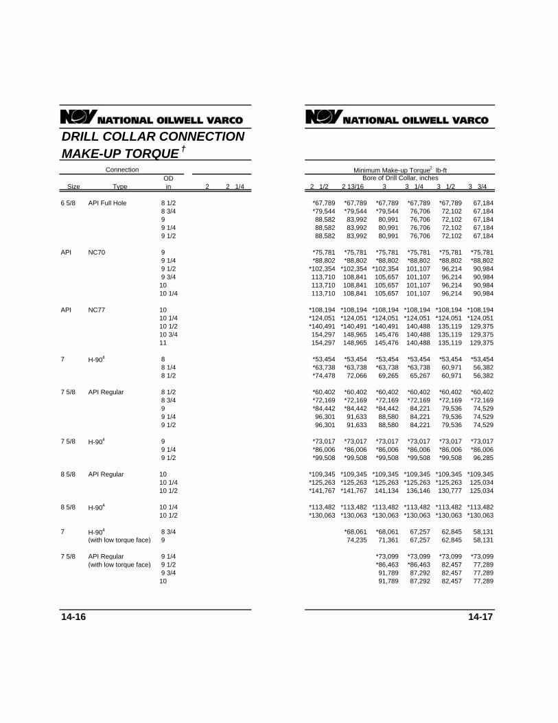
DRILL COLLAR CONNECTIONMAKE-UP TORQUE †
ODSize Type in 2 2 1/4 2 1/2 2 13/16 3 3 1/4 3 1/2 3 3/4
6 5/8 API Full Hole 8 1/2 *67,789 *67,789 *67,789 *67,789 *67,789 67,1848 3/4 *79,544 *79,544 *79,544 76,706 72,102 67,1849 88,582 83,992 80,991 76,706 72,102 67,1849 1/4 88,582 83,992 80,991 76,706 72,102 67,1849 1/2 88,582 83,992 80,991 76,706 72,102 67,184
API NC70 9 *75,781 *75,781 *75,781 *75,781 *75,781 *75,7819 1/4 *88,802 *88,802 *88,802 *88,802 *88,802 *88,8029 1/2 *102,354 *102,354 *102,354 101,107 96,214 90,9849 3/4 113,710 108,841 105,657 101,107 96,214 90,984
10 113,710 108,841 105,657 101,107 96,214 90,98410 1/4 113,710 108,841 105,657 101,107 96,214 90,984
API NC77 10 *108,194 *108,194 *108,194 *108,194 *108,194 *108,19410 1/4 *124,051 *124,051 *124,051 *124,051 *124,051 *124,05110 1/2 *140,491 *140,491 *140,491 140,488 135,119 129,37510 3/4 154,297 148,965 145,476 140,488 135,119 129,37511 154,297 148,965 145,476 140,488 135,119 129,375
7 H-904 8 *53,454 *53,454 *53,454 *53,454 *53,454 *53,4548 1/4 *63,738 *63,738 *63,738 *63,738 60,971 56,3828 1/2 *74,478 72,066 69,265 65,267 60,971 56,382
7 5/8 API Regular 8 1/2 *60,402 *60,402 *60,402 *60,402 *60,402 *60,4028 3/4 *72,169 *72,169 *72,169 *72,169 *72,169 *72,1699 *84,442 *84,442 *84,442 84,221 79,536 74,5299 1/4 96,301 91,633 88,580 84,221 79,536 74,5299 1/2 96,301 91,633 88,580 84,221 79,536 74,529
7 5/8 H-904 9 *73,017 *73,017 *73,017 *73,017 *73,017 *73,0179 1/4 *86,006 *86,006 *86,006 *86,006 *86,006 *86,0069 1/2 *99,508 *99,508 *99,508 *99,508 *99,508 96,285
8 5/8 API Regular 10 *109,345 *109,345 *109,345 *109,345 *109,345 *109,34510 1/4 *125,263 *125,263 *125,263 *125,263 *125,263 125,03410 1/2 *141,767 *141,767 141,134 136,146 130,777 125,034
8 5/8 H-904 10 1/4 *113,482 *113,482 *113,482 *113,482 *113,482 *113,48210 1/2 *130,063 *130,063 *130,063 *130,063 *130,063 *130,063
7 H-904 8 3/4 *68,061 *68,061 67,257 62,845 58,131(with low torque face) 9 74,235 71,361 67,257 62,845 58,131
7 5/8 API Regular 9 1/4 *73,099 *73,099 *73,099 *73,099(with low torque face) 9 1/2 *86,463 *86,463 82,457 77,289
9 3/4 91,789 87,292 82,457 77,28910 91,789 87,292 82,457 77,289
14-16 14-17
Connection Minimum Make-up Torque2 lb-ftBore of Drill Collar, inches

DRILL COLLAR CONNECTIONMAKE-UP TORQUE †
ODSize Type in 2 2 1/4 2 1/2 2 13/16 3 3 1/4 3 1/2 3 3/4
7 5/8 H-904 9 3/4 *91,667 *91,667 *91,667 *91,667 *91,667(with low torque face) 10 *106,260 *106,260 *106,260 104,171 98,804
10 1/4 117,112 113,851 109,188 104,171 98,80410 1/2 117,112 113,851 109,188 104,171 98,804
8 5/8 API Regular 10 3/4 *112,883 *112,883 *112,883 *112,883(with low torque face) 11 *130,672 *130,672 *130,672 *130,672
11 1/4 147,616 142,430 136,846 130,871
8 5/8 H-904 10 3/4 *92,960 *92,960 *92,960 *92,960(with low torque face) 11 *110,781 *110,781 *110,781 *110,781
11 1/4 *129,203 *129,203 *129,203 *129,203
† Recommended Make-Up Torque1 For Rotary 2 Normal torque range is tabulated value plus 10%.Shouldered Drill Collar Connections Higher torque values may be used under extreme
conditions.
Notes: 3 Make-up torque for 2 7/8 PAC connection is based on87,500 psi stress and other factors listed in footnote 1.
1. Torque figures preceded by an asterisk (*) indicate thatthe weaker member for the corresponding outside 4 Make-up torque for H-90 connection is based ondiameter (OD) and bore is the BOX; For all other torque 56,200 psi stress and other factors listed in footnote 1.values the weaker member is the PIN.
2. In each connection size and type group, torque valuesapply to all connection types in the group, when used This table taken from API Recommended Practice 7G, Sixteenthwith the same drill collar outside diameter and bore, Edition, December 1, 1998.i.e. 2 3/8 API IF, API NC26, and 2 7/8 Slim Holeconnections used with 3 1/2 x 1 1/4 drill collars all havethe same minimum make-up torque of 4,600 ft.lb., andthe BOX is the weaker member.
3. Stress-relief features are disregarded for make-uptorque.
Footnotes:
1 Basis of calculations for recommended make-uptorque assumed the use of a thread compoundcontaining 40-60% by weight of finely powered metalliczinc or 60% by weight of finely powered metallic lead,with not more than 0.3% total active sulfur appliedthoroughly to all threads and shoulders and using themodified screw jack formula in API RP7G (16th edition)Appendix A, paragraph A.8, and a unit stress of 62,500psi in the box or pin, whichever is weaker.
14-18 14-19
Minimum Make-up Torque2 lb-ftBore of Drill Collar, inches
Connection

PROPERTIES OF DRILL PIPESAND TOOL JOINTS †
Drill Pipe Min Box Make-up Min Box Make-upType Min Shoulder Torque Min Shoulder TorqueUpset OD With for Min OD With for Min
Nom Nom and New New Tool Eccentric OD Tool Tool Eccentric OD ToolSize Weight Grade Connection OD ID Joint Wear Joint Joint Wear Joint
in lb/ft in in in in lb-ft in in lb-ft
2 3/8 4.85 EU-E75 NC26 3 3/8 1 3/4 4,125 B 3 1/8 3/64 1,945 3 3/32 1/32 1,6894.85 EU-E75 W.O. 3 3/8 2 2,586 P 3 1/16 1/16 1,994 3 1/32 3/64 1,7464.85 EU-E75 2 3/8 OHLW 3 1/8 2 2,713 P 3 1/16 1,830 2 31/32 3/64 1,5894.85 EU-E75 2 3/8 SL-H90 3 1/4 2 3,074 P 2 31/32 1/16 1,996 2 15/16 3/64 1,726
2 3/8 6.65 IU-E75 2 3/8 PAC2 2 7/8 1 3/8 2,813 P 2 25/32 9/64 2,455 2 23/32 7/64 2,0556.65 EU-E75 NC26 3 3/8 1 3/4 4,125 B 3 3/16 5/64 2,467 3 5/32 1/16 2,2046.65 EU-E75 2 3/8 SL-H90 3 1/4 2 3,074 P 3 1/32 3/32 2,549 2 31/32 1/16 1,9966.65 EU-E75 2 3/8 OHSW 3 1/4 1 3/4 3,891 B 3 1/16 3/32 2,324 3 1/32 5/64 2,075
2 3/8 6.65 EU-X95 NC26 3 3/8 1 3/4 4,125 B 3 1/4 7/64 3,005 3 7/32 3/32 2,734
2 3/8 6.65 EU-G105 NC262 3 3/8 1 3/4 4,125 B 3 9/32 1/8 3,279 3 1/4 7/64 3,005
2 7/8 6.85 EU-E75 NC31 4 1/8 2 1/8 7,122 P 3 11/16 5/64 3,154 3 21/32 1/16 2,8046.85 EU-E75 2 7/8 WO 4 1/8 2 7/16 4,318 P 3 5/8 5/64 3,216 3 19/32 1/16 2,8766.85 EU-E75 2 7/8 OHLW2 3 3/4 2 7/16 3,351 P 3 1/2 7/64 3,297 3 7/16 5/64 2,6666.85 EU-E75 2 7/8 SL-H90 3 7/8 2 7/16 4,575 P 3 1/2 3/32 3,397 3 7/16 1/16 2,666
2 7/8 10.40 EU-E75 NC31 4 1/8 2 1/8 7,122 P 3 13/16 9/64 4,597 3 3/4 7/64 3,86710.40 IU-E75 2 7/8 XH 4 1/4 1 7/8 7,969 P 3 23/32 9/64 4,357 3 21/32 7/64 3,66410.40 IU-E75 NC262 3 3/8 1 3/4 4,125 B 3 3/8 11/64 4,125 3 11/32 5/32 3,83910.40 EU-E75 2 7/8 OHSW2 3 7/8 2 5/32 5,270 P 3 19/32 5/32 4,273 3 9/16 7/64 3,94110.40 EU-E75 2 7/8 SL-H90 3 7/8 2 5/32 6,773 P 3 19/32 9/64 4,529 3 17/32 7/64 3,77010.40 IU-E75 2 7/8 PAC2 3 1/8 1 1/2 3,439 P 3 1/8 15/64 3,439 3 1/8 15/64 3,439
2 7/8 10.40 EU-X95 NC31 4 1/8 2 7,918 P 3 29/32 3/16 5,726 3 27/32 5/32 4,96910.40 EU-X95 2 7/8 SL-H902 3 7/8 2 5/32 6,773 P 3 11/16 3/16 5,702 3 5/8 5/32 4,915
2 7/8 10.40 EU-G105 NC31 4 1/8 2 7,918 P 3 15/16 13/64 6,110 3 7/8 11/64 5,345
2 7/8 10.40 EU-S135 NC31 4 3/8 1 5/8 10,167 P 4 1/16 17/64 7,694 4 15/64 6,893
3 1/2 9.50 EU-E75 NC38 4 3/4 3 7,688 P 4 13/32 1/8 5,773 4 11/32 3/32 4,7979.50 EU-E75 NC38 4 3/4 2 11/16 10,864 P 4 13/32 1/8 5,773 4 11/32 3/32 4,7979.50 EU-E75 3 1/2 OHLW 4 3/4 3 7,218 P 4 9/32 1/8 5,340 4 1/4 7/64 4,8689.50 EU-E75 3 1/2 SL-H90 4 5/8 3 7,584 P 4 3/16 7/64 5,521 4 5/32 3/32 5,003
3 1/2 13.30 EU-E75 NC38 4 3/4 2 11/16 10,864 P 4 1/2 11/64 7,274 4 7/16 9/64 6,26813.30 IU-E75 NC312 4 1/8 2 1/8 7,122 P 4 15/64 6,893 3 15/16 13/64 6,11013.30 EU-E75 3 1/2 OHSW 4 3/4 2 11/16 10,387 P 4 13/32 3/16 7,278 4 11/32 5/32 6,29913.30 EU-E75 3 1/2 H90 5 1/4 2 3/4 14,300 P 4 17/32 1/8 7,064 4 1/2 7/64 6,48713.30 EU-X95 NC38 5 2 9/16 12,196 P 4 19/32 7/32 8,822 4 17/32 3/16 7,78513.30 EU-X95 3 1/2 SL-H902 4 5/8 2 11/16 11,137 P 4 3/8 13/64 8,742 4 5/16 11/64 7,64713.30 EU-X95 3 1/2 H90 5 1/4 2 3/4 14,300 P 4 5/8 11/64 8,826 4 9/16 9/64 7,646
3 1/2 13.30 EU-G105 NC38 5 2 7/16 13,328 P 4 21/32 1/4 9,879 4 19/32 7/32 8,822
3 1/2 13.30 EU-S135 NC40 5 3/8 2 7/16 17,958 P 5 9/32 12,569 4 29/32 15/64 10,76813.30 EU-S135 NC38 5 2 1/8 15,909 P 4 13/16 21/64 12,614 4 23/32 9/32 10,957
14-20 14-21
New Tool Joint Data
lb-ft
Class 2Premium Class
Make-upTorque6

PROPERTIES OF DRILL PIPESAND TOOL JOINTS †
Drill Pipe Min Box Make-up Min Box Make-upType Min Shoulder Torque Min Shoulder TorqueUpset OD With for Min OD With for Min
Nom Nom and New New Tool Eccentric OD Tool Tool Eccentric OD ToolSize Weight Grade Connection OD ID Joint Wear Joint Joint Wear Joint
in lb/ft in in in in lb-ft in in lb-ft
3 1/2 15.50 EU-E75 NC38 5 2 9/16 12,196 P 4 17/32 3/16 7,785 4 15/32 5/32 6,769
3 1/2 15.50 EU-X95 NC38 5 2 7/16 13,328 P 4 21/32 1/4 9,879 4 19/32 7/32 8,822
3 1/2 15.50 EU-G105 NC38 5 2 1/8 15,909 P 4 23/32 9/32 10,957 4 5/8 15/64 9,34815.50 EU-G105 NC40 5 1/4 2 9/16 16,656 P 4 15/16 1/4 11,363 4 27/32 13/64 9,595
3 1/2 15.50 EU-S135 NC40 5 1/2 2 1/4 19,766 P 5 3/32 21/64 14,419 4 31/32 17/64 11,963
4 11.85 EU-E75 NC46 6 3 1/4 20,175 P 5 7/32 7/64 7,843 5 5/32 5/64 6,47611.85 EU-E75 4 WO 5 3/4 3 7/16 17,285 P 5 7/32 7/64 7,843 5 5/32 5/64 6,47611.85 EU-E75 4 OHLW 5 1/4 3 15/32 13,186 P 5 9/64 7,866 4 15/16 7/64 6,59311.85 IU-E75 4 H90 5 1/2 2 13/16 21,224 P 4 7/8 7/64 7,630 4 27/32 3/32 6,962
4 14.00 IU-E75 NC40 5 1/4 2 13/16 14,092 P 4 13/16 3/16 9,017 4 3/4 5/32 7,87714.00 EU-E75 NC46 6 3 1/4 20,175 P 5 9/32 9/64 9,233 5 7/32 7/64 7,84314.00 IU-E75 4 SH2 4 5/8 2 9/16 9,102 P 4 7/16 15/64 8,782 4 3/8 13/64 7,81714.00 EU-E75 4 OHSW 5 1/2 3 1/4 16,320 P 5 1/16 11/64 9,131 5 9/64 7,83914.00 IU-E75 4 H90 5 1/2 2 13/16 21,224 P 4 15/16 9/64 8,986 4 7/8 7/64 7,630
4 14.00 IU-X95 NC40 5 1/4 2 11/16 15,404 P 4 15/16 1/4 11,363 4 27/32 13/64 9,59514.00 EU-X95 NC46 6 3 1/4 20,175 P 5 3/8 3/16 11,363 5 5/16 5/32 9,93714.00 IU-X95 4 H90 5 1/2 2 13/16 21,224 P 5 1/32 3/16 11,065 4 31/32 5/32 9,673
4 14.00 IU-G105 NC40 5 1/2 2 7/16 18,068 P 5 9/32 12,569 4 29/32 15/64 10,76814.00 EU-G105 NC46 6 3 1/4 20,175 P 5 7/16 7/32 12,813 5 11/32 11/64 10,64714.00 IU-G105 4 H90 5 1/2 2 13/16 21,224 P 5 3/32 7/32 12,481 5 1/32 3/16 11,065
4 14.00 EU-S135 NC46 6 3 23,538 P 5 9/16 9/32 15,787 5 1/2 1/4 14,288
4 15.70 IU-E75 NC40 5 1/4 2 11/16 15,404 P 4 7/8 7/32 10,179 4 25/32 11/64 8,44415.70 EU-E75 NC46 6 3 1/4 20,175 P 5 5/16 5/32 9,937 5 1/4 1/8 8,53515.70 IU-E75 4 H90 5 1/2 2 13/16 21,224 P 4 31/32 5/32 9,673 4 29/32 1/8 8,305
4 15.70 IU-X95 NC40 5 1/2 2 7/16 18,068 P 5 9/32 12,569 4 29/32 15/64 10,76815.70 EU-X95 NC46 6 3 23,538 P 5 7/16 7/32 12,813 5 11/32 11/64 10,64715.70 IU-X95 4 H90 5 1/2 2 13/16 21,224 P 5 3/32 7/32 12,481 5 1/32 3/16 11,065
4 15.70 EU-G105 NC46 6 3 23,538 P 5 15/32 15/64 13,547 5 13/32 13/64 12,08515.70 IU-G105 4 H90 5 1/2 2 13/16 21,224 P 5 5/32 1/4 13,922 5 1/16 13/64 11,770
4 15.70 IU-S135 NC46 6 2 5/8 26,982 B 5 21/32 21/64 18,083 5 17/32 17/64 15,03515.70 EU-S135 NC46 6 2 7/8 25,118 P 5 21/32 21/64 18,083 5 17/32 17/64 15,035
4 1/2 16.60 IEU-E75 4 1/2 FH 6 3 20,868 P 5 3/8 13/64 12,125 5 9/32 5/32 10,07216.60 IEU-E75 NC46 6 1/4 3 1/4 20,396 P 5 13/32 13/64 12,085 5 11/32 11/64 10,64716.60 IEU-E75 4 1/2 OHSW 5 7/8 3 3/4 16,346 P 5 7/16 13/64 11,862 5 3/8 11/64 10,37516.60 EU-E75 NC50 6 5/8 3 3/4 22,836 P 5 23/32 5/32 11,590 5 11/16 9/64 10,77316.60 IEU-E75 4 1/2 H90 6 3 1/4 23,355 P 5 11/32 3/16 12,215 5 9/32 5/32 10,642
14-22 14-23
New Tool Joint Data
Class 2Premium Class
Make-upTorque6
lb-ft

PROPERTIES OF DRILL PIPESAND TOOL JOINTS †
Drill Pipe Min Box Make-up Min Box Make-upType Min Shoulder Torque Min Shoulder TorqueUpset OD With for Min OD With for Min
Nom Nom and New New Tool Eccentric OD Tool Tool Eccentric OD ToolSize Weight Grade Connection OD ID Joint Wear Joint Joint Wear Joint
in lb/ft in in in in lb-ft in in lb-ft
4 1/2 16.60 IEU-X95 4 1/2 FH 6 2 3/4 23,843 P 5 1/2 17/64 14,945 5 13/32 7/32 12,82116.60 IEU-X95 NC46 6 1/4 3 1/4 20,396 P 5 17/32 17/64 15,035 5 7/16 7/32 12,81316.60 EU-X95 NC50 6 5/8 3 3/4 22,836 P 5 27/32 7/32 14,926 5 25/32 3/16 13,24516.60 IEU-X95 4 1/2 H90 6 3 27,091 P 5 15/32 1/4 15,441 5 3/8 13/64 13,102
4 1/2 16.60 IEU-G105 4 1/2 FH 6 2 3/4 23,843 P 5 9/16 19/64 16,391 5 15/32 1/4 14,23116.60 IEU-G105 NC46 6 1/4 3 23,795 P 5 19/32 19/64 16,546 5 1/2 1/4 14,28816.60 EU-G105 NC50 6 5/8 3 3/4 22,836 P 5 29/32 1/4 16,633 5 13/16 13/64 14,08216.60 IEU-G105 4 1/2 H90 6 3 27,091 P 5 1/2 17/64 16,264 5 7/16 15/64 14,625
4 1/2 16.60 IEU-S135 NC46 6 1/4 2 3/4 26,923 P 5 25/32 25/64 21,230 5 21/32 21/64 18,08316.60 EU-S135 NC50 6 5/8 3 1/2 27,076 P 6 1/16 21/64 21,017 5 31/32 9/32 18,367
4 1/2 20.00 IEU-E75 4 1/2 FH 6 3 20,868 P 5 15/32 1/4 14,231 5 3/8 13/64 12,12520.00 IEU-E75 NC46 6 1/4 3 23,795 P 5 1/2 1/4 14,288 5 13/32 13/64 12,08520.00 EU-E75 NC50 6 5/8 3 5/8 24,993 P 5 13/16 13/64 14,082 5 3/4 3/16 12,41520.00 IEU-E75 4 1/2 H90 6 3 27,091 P 5 13/32 7/32 13,815 5 11/32 3/16 12,215
4 1/2 20.00 IEU-X95 4 1/2 FH 6 2 1/2 26,559 P 5 5/8 21/64 17,861 5 17/32 9/32 15,66520.00 IEU-X95 NC46 6 1/4 2 3/4 26,923 P 5 21/32 21/64 18,083 5 9/16 9/32 15,78720.00 EU-X95 NC50 6 5/8 3 1/2 27,076 P 5 15/16 17/64 17,497 5 7/8 15/64 15,77620.00 IEU-X95 4 1/2 H90 6 3 27,091 P 5 9/16 19/64 17,929 5 15/32 1/4 15,441
4 1/2 20.00 IEU-G105 NC46 6 1/4 2 1/2 29,778 P 5 23/32 23/64 19,644 5 5/8 5/16 17,31120.00 EU-G105 NC50 6 5/8 3 1/2 27,076 P 6 1/32 5/16 20,127 5 29/32 1/4 16,633
4 1/2 20.00 EU-S135 NC50 6 5/8 2 7/8 36,398 P 6 7/32 13/32 25,569 6 3/32 11/32 21,914
5 19.50 IEU-E75 NC50 6 5/8 3 3/4 22,836 P 5 7/8 15/64 15,776 5 13/16 13/64 14,082
5 19.50 IEU-X95 NC50 6 5/8 3 1/2 27,076 P 6 1/32 5/16 20,127 5 15/16 17/64 17,49719.50 IEU-X95 5 H90 6 1/2 3 1/4 31,084 P 5 27/32 19/64 19,862 5 3/4 1/4 17,116
5 19.50 IEU-G105 NC50 6 5/8 3 1/4 31,025 P 6 3/32 11/32 21,914 6 19/64 19,24419.50 IEU-G105 5 H90 6 1/2 3 35,039 P 5 29/32 21/64 21,727 5 13/16 9/32 18,940
5 19.50 IEU-S135 NC50 6 5/8 2 3/4 38,044 P 6 5/16 29/64 28,381 6 3/16 25/64 24,64519.50 IEU-S135 5 1/2 FH 7 1/4 3 1/2 43,490 P 6 3/4 3/8 28,737 6 5/8 5/16 24,412
5 25.60 IEU-E75 NC50 6 5/8 3 1/2 27,076 P 6 1/32 5/16 20,127 5 15/16 17/64 17,49725.60 IEU-E75 5 1/2 FH 7 3 1/2 37,742 B 6 1/2 1/4 20,205 6 13/32 13/64 17,127
5 25.60 IEU-X95 NC50 6 5/8 3 34,680 P 6 7/32 13/32 25,569 6 3/32 11/32 21,91425.60 IEU-X95 5 1/2 FH 7 3 1/2 37,742 B 6 21/32 21/64 25,483 6 9/16 9/32 22,294
5 25.60 IEU-G105 NC50 6 5/8 2 3/4 38,044 P 6 9/32 7/16 27,437 6 5/32 3/8 23,72825.60 IEU-G105 5 1/2 FH 7 1/4 3 1/2 43,490 P 6 23/32 23/64 27,645 6 5/8 5/16 24,412
5 25.60 IEU-S135 5 1/2 FH 7 1/4 3 1/4 47,230 B 6 15/16 15/32 35,446 6 13/16 13/32 30,943
14-24 14-25
Make-upTorque6
lb-ft
Premium Class
New Tool Joint Data
Class 2

PROPERTIES OF DRILL PIPESAND TOOL JOINTS †
Drill Pipe Min Box Make-up Min Box Make-upType Min Shoulder Torque Min Shoulder TorqueUpset OD With for Min OD With for Min
Nom Nom and New New Tool Eccentric OD Tool Tool Eccentric OD ToolSize Weight Grade Connection OD ID Joint Wear Joint Joint Wear Joint
in lb/ft in in in in lb-ft in in lb-ft
5 1/2 21.90 IEU-E75 5 1/2 FH 7 4 33,560 P 6 15/32 15/64 19,172 6 13/32 13/64 17,127
5 1/2 21.90 IEU-X95 5 1/2 FH 7 3 3/4 37,742 B 6 5/8 5/16 24,412 6 17/32 17/64 21,24621.90 IEU-X95 5 1/2 H90 7 3 1/2 35,454 P 6 3/16 21/64 24,414 6 3/32 9/32 21,349
5 1/2 21.90 IEU-G105 5 1/2 FH 7 1/4 3 1/2 43,490 P 6 23/32 23/64 27,645 6 19/32 19/64 23,350
5 1/2 21.90 IEU-S135 5 1/2 FH 7 1/2 3 53,302 P 6 15/16 15/32 35,446 6 13/16 13/32 30,943
5 1/2 24.70 IEU-E75 5 1/2 FH 7 4 33,560 P 6 9/16 9/32 22,294 6 15/32 15/64 19,172
5 1/2 24.70 IEU-X95 5 1/2 FH 7 1/4 3 1/2 43,490 P 6 23/32 23/64 27,645 6 19/32 19/64 23,350
5 1/2 24.70 IEU-G105 5 1/2 FH 7 1/4 3 1/2 43,490 P 6 25/32 25/64 29,836 6 11/16 11/32 26,560
5 1/2 24.70 IEU-S135 5 1/2 FH 7 1/2 3 52,302 P 7 1/32 33/64 38,901 6 7/8 7/16 33,180
6 5/8 25.20 IEU-E75 6 5/8 FH 8 5 44,196 P 7 7/16 1/4 26,810 7 3/8 7/32 24,100IEU-X95 6 5/8 FH 8 5 44,196 P 7 5/8 11/32 35,139 7 1/2 9/32 29,552
IEU-G105 6 5/8 FH 8 1/4 4 3/4 51,742 P 7 11/16 5/8 37,983 7 19/32 21/64 33,730IEU-S135 6 5/8 FH 8 1/2 4 1/4 65,535 P 7 29/32 31/64 48,204 7 25/32 27/64 42,312
6 5/8 27.70 IEU-E75 6 5/8 FH 8 5 44 196 P 7 1/2 9/32 29,552 7 13/32 15/64 25,451IEU-X95 6 5/8 FH 8 1/4 4 3/4 51,742 P 7 11/16 3/8 37,983 7 9/16 5/16 32,329
IEU-G105 6 5/8 FH 8 1/4 4 3/4 51,742 P 7 3/4 13/32 40,860 7 21/32 23/64 36,556IEU-S135 6 5/8 FH 8 1/2 4 1/4 65,535 P 8 17/32 52,714 7 27/64 29/64 45,241
† Recommended minimum OD and make-up torque of 4 In calculation of torsional strengths of tool joints, bothweld-on type tool joints based on torsional strength of box new and worn, the bevels of the tool joint shoulders areand drill pipe. disregarded. This thickness measurement should beTool joint diameters specified are required to retain made in the plane of the face from the ID of the countertorsional strength in the tool joint comparable to the bore to the outside diameter of the box, disregardingtorsional strength of the attached drill pipe. These should the bevels.be adequate for all service. Tool joints with torsionalstrengths considerably below that of the drill pipe may be 5 Any tool joint with an outside diameter less than APIadequate for much drilling service. bevel diameter should be provided with a minimum
1/32" depth x 45° bevel on the outside and insideFootnotes: diameter of the box shoulder and outside diameter of
the pin shoulder.1 The use of outside diameters (OD) smaller than those
listed in the table may be acceptable due to special service 6 P = Pin limit, B = Box limit.requirements.
2 Tool joint with dimensions shown has lower torsional yieldratio than the 0.80 which is generally used. This table taken from API Recommended Practice 7G, Sixteenth
Edition, December 1, 1998.3 Recommended make-up torque is based on 72,000 ps
stress.
14-26 14-27
Torque6
lb-ft
New Tool Joint DataMake-up
Class 2Premium Class

MECHANICAL PROPERTIESOF DRILL PIPE †
1NominalSize WeightOD Newin lb/ft Class E75 X95 G105 S135 E75 X95 G105 S135
2 3/8 4.85 New 4,763 6,033 6,668 8,574 97,817 123,902 136,944 176,071Premium 3,725 4,719 5,215 6,705 76,893 97,398 107,650 138,407Class 2 3,224 4,083 4,513 5,802 66,686 84,469 93,360 120,035
6.65 New 6,250 7,917 8,751 11,251 138,214 175,072 193,500 248,786Premium 4,811 6,093 6,735 8,659 107,616 136,313 150,662 193,709Class 2 4,130 5,232 5,782 7,434 92,871 117,636 130,019 167,167
2 7/8 6.85 New 8,083 10,238 11,316 14,549 135,902 172,143 190,263 244,624Premium 6,332 8,020 8,865 11,397 106,946 135,465 149,725 192,503Class 2 5,484 6,946 7,677 9,871 92,801 117,549 129,922 167,043
10.40 New 11,554 14,635 16,176 20,798 214,344 271,503 300,082 385,820Premium 8,858 11,220 12,401 15,945 166,535 210,945 233,149 299,764Class 2 7,591 9,615 10,627 13,663 143,557 181,839 200,980 258,403
3 1/2 9.50 New 14,146 17,918 19,805 25,463 194,264 246,068 271,970 349,676Premium 11,094 14,052 15,531 19,968 152,979 193,774 214,171 275,363Class 2 9,612 12,176 13,457 17,302 132,793 168,204 185,910 239,027
13.30 New 18,551 23,498 25,972 33,392 271,569 343,988 380,197 488,825Premium 14,361 18,191 20,106 25,850 212,150 268,723 297,010 381,870Class 2 12,365 15,663 17,312 22,258 183,398 232,304 256,757 330,116
15.50 New 21,086 26,708 29,520 37,954 322,775 408,848 451,885 580,995Premium 16,146 20,452 22,605 29,063 250,620 317,452 350,868 451,115Class 2 13,828 17,515 19,359 24,890 215,967 273,558 302,354 388,741
4 11.85 New 19,474 24,668 27,264 35,054 230,755 292,290 323,057 415,360Premium 15,310 19,392 21,433 27,557 182,016 230,554 254,823 327,630Class 2 13,281 16,823 18,594 23,907 158,132 200,301 221,385 284,638
14.00 New 23,288 29,498 32,603 41,918 285,359 361,454 399,502 513,646Premium 18,196 23,048 25,474 32,752 224,182 283,963 313,854 403,527Class 2 15,738 19,935 22,034 28,329 194,363 246,193 272,108 349,852
15.70 New 25,810 32,692 36,134 46,458 324,118 410,550 453,765 583,413Premium 20,067 25,418 28,094 36,120 253,851 321,544 355,391 456,931Class 2 17,315 21,932 24,241 31,166 219,738 278,335 307,633 395,528
4 1/2 13.75 New 25,907 32,816 36,270 46,633 270,034 342,043 378,047 486,061Premium 20,403 25,844 28,564 36,725 213,258 270,127 298,561 383,864Class 2 17,715 22,439 24,801 31,887 185,389 234,827 259,545 333,701
16.60 New 30,807 39,022 43,130 55,453 330,558 418,707 462,781 595,004Premium 24,139 30,576 33,795 43,450 260,165 329,542 364,231 468,297Class 2 20,908 26,483 29,271 37,634 225,771 285,977 316,080 406,388
20.00 New 36,901 46,741 51,661 66,421 412,358 522,320 577,301 742,244Premium 28,683 36,332 40,157 51,630 322,916 409,026 452,082 581,248Class 2 24,747 31,346 34,645 44,544 279,502 354,035 391,302 503,103
22.82 New 40,912 51,821 57,276 73,641 471,239 596,903 659,734 848,230Premium 31,587 40,010 44,222 56,856 367,566 465,584 514,593 661,620Class 2 27,161 34,404 38,026 48,890 317,497 402,163 444,496 571,495
14-28 14-29
Torsional Yield Strengthlb-ft
3Tensile Data2Torsional DataLoad at Minimum Yield Strength
lb

MECHANICAL PROPERTIESOF DRILL PIPE †
1NominalSize WeightOD Newin lb/ft Class E75 X95 G105 S135 E75 X95 G105 S135
5 16.25 New 35,044 44,389 49,062 63,079 328,073 415,559 459,302 590,531Premium 27,607 34,969 38,650 49,693 259,155 328,263 362,817 466,479Class 2 23,974 30,368 33,564 43,154 225,316 285,400 315,442 405,568
19.50 New 41,167 52,144 57,633 74,100 395,595 501,087 553,833 712,070Premium 32,285 40,895 45,199 58,113 311,535 394,612 436,150 560,764Class 2 27,976 35,436 39,166 50,356 270,432 342,548 378,605 486,778
25.60 New 52,257 66,192 73,159 94,062 530,144 671,515 742,201 954,259Premium 40,544 51,356 56,762 72,979 414,690 525,274 580,566 746,443Class 2 34,947 44,267 48,926 62,905 358,731 454,392 502,223 645,715
5 1/2 19.20 New 44,074 55,826 61,703 79,332 372,181 471,429 521,053 669,925Premium 34,764 44,035 48,670 62,575 294,260 372,730 411,965 529,669Class 2 30,208 38,263 42,291 54,374 255,954 324,208 358,335 460,717
21.90 New 50,710 64,233 70,994 91,278 437,116 553,681 611,963 786,809Premium 39,863 50,494 55,809 71,754 344,780 436,721 482,692 620,604Class 2 34,582 43,804 48,414 62,247 299,533 379,409 419,346 539,160
24.70 New 56,574 71,660 79,204 101,833 497,222 629,814 696,111 894,999Premium 44,320 56,139 62,048 79,776 391,285 495,627 547,799 704,313Class 2 38,383 48,619 53,737 69,090 339,533 430,076 475,347 611,160
6 5/8 25.20 New 70,580 89,402 98,812 127,044 489,464 619,988 685,250 881,035Premium 55,766 71,522 79,050 101,635 387,466 490,790 542,452 697,438Class 2 48,497 61,430 67,896 87,295 337,236 427,166 472,131 607,026
27.70 New 76,295 96,640 106,813 137,330 534,199 676,651 747,877 961,556Premium 60,192 77,312 85,450 109,864 422,419 535,064 591,387 760,354Class 2 52,308 66,257 73,231 94,155 367,455 465,443 514,437 661,419
† New Drill Pipe Torsional and Tensile Data, Used Drill Pipe Premium ClassTorsional and Tensile Data API Premium Class, and Used 2 Based on the shear strength equal to 57.7 percent ofDrill Pipe Torsional and Tensile Data API Class 2. minimum yield strength.
Torsional data based on 20 percent uniform wear onFootnotes: outside diameter.
3 Tensile data based on 20 percent uniform wear on outside1 New weight, nominal with threads and couplings. diameter.
New Drill Pipe Class 22 Based on the shear strength equal to 57.7 percent of 2 Based on the shear strength equal to 57.7 percent of
minimum yield strength and nominal wall thickness. minimum yield strength.Minimum torsional yield strength calculated from Torsional data based on 30 percent uniform wear onequation in RP7G, (16th edition) Appendix A, paragraph outside diameter.A.15. 3 Tensile data based on 30 percent uniform wear on outside
3 Tensile data based on minimum values. diameter.Minimum tensile strength calculated from equation in APIRP7G, (16th edition) Appendix A, paragraph A.13.
This table taken from API Recommended Practice 7G, SixteenthEdition, December 1, 1998.
14-30 14-31
Torsional Yield Strengthlb-ft
2Torsional DataLoad at Minimum Yield Strength
lb
3Tensile Data

HEAVY WALLED DRILL PIPE
NominalSize ID
in in3 1/2 2 1/163 1/2 2 1/44 2 9/164 1/2 2 3/45 35 1/2 3 3/86 5/8 4 1/2
Nominal ConnectionSize Size OD ID
in in in3 1/2 NC38 (3 1/2 IF) 4 3/4 2 3/163 1/2 NC38 (3 1/2 IF) 4 3/4 2 3/84 NC40 (4 FH) 5 1/4 2 11/164 1/2 NC46 (4 IF) 6 1/4 2 7/85 NC50 (4 1/2 IF) 6 5/8 3 1/165 1/2 5 1/2 FH 7 3 1/26 5/8 6 5/8 FH 8 4 1/2
NominalSize Wt/ft
in lb3 1/2 25.33 1/2 23.24 27.24 1/2 41.05 49.35 1/2 57.06 5/8 70.8
14-32
Tool Joint
Approximate Weight(including tube & joints)
1.0631.063
Wt/Jt 30 ftlb
760695815
1,2301,4801,8802,290
TubeWall
Thicknessin
0.7190.6250.7190.8751.000

DRILL BIT SIZES
Rotary Size of Rotary Size ofPin Bit Pin Bit
Connection inches Connection inches2 3/8 REG 3 3/4 6 5/8 REG 9 1/2
3 7/8 9 5/84 1/8 9 3/44 1/4 9 7/84 3/8 10 5/84 1/2 11
2 7/8 REG 4 5/8 11 1/24 3/4 11 5/84 7/8 11 3/45 12
3 1/2 REG 5 1/8 12 1/45 3/8 13 1/25 5/8 13 3/45 3/4 14 3/45 7/8 156 166 1/8 176 1/4 17 1/26 3/8 18 1/26 1/2 7 5/8 REG 14 1/26 5/8 14 3/46 3/4 157 167 3/8 17
4 1/2 REG 7 1/2 17 1/27 5/8 18 1/27 3/4 207 7/8 228 1/8 238 3/8 248 1/2 268 5/8 8 5/8 REG 18 5/88 3/4 209 229 3/8 23
242627
and larger
14-33

HOLE CURVATURE
BUILD BUILDRATE RADIUS OF HOLE RATE RADIUS OF HOLE
DEGREES DEGREESper 100 ft R1 R2 per 100 ft R1 R2
(30m) FEET METERS (30m) FEET METERS2 2865 859 105 55 164 1432 430 110 52 166 955 286 115 50 158 716 215 120 48 14
10 573 172 125 46 1412 477 143 130 44 1314 409 123 135 42 1316 358 107 140 41 1218 318 95 145 40 1220 286 86 150 38 1122 260 78 155 37 1124 239 72 160 36 1126 220 66 165 35 1028 205 61 170 34 1030 191 57 175 33 1032 179 54 180 32 1034 169 51 185 31 936 159 48 190 30 938 151 45 195 29 940 143 43 200 29 942 136 41 210 27 844 130 39 220 26 846 125 37 230 25 748 119 36 240 24 750 115 34 250 23 752 110 33 260 22 754 106 32 270 21 656 102 31 280 20 658 99 30 290 20 660 95 29 300 19 662 92 2864 90 27 FORMULA:66 87 2668 84 2570 82 2572 80 2474 77 2376 75 2378 73 2280 72 2182 70 2184 68 2086 67 2088 65 2090 64 1992 62 1994 61 1896 60 1898 58 18100 57 17
14-34
)( Angle x .017453(ft)Length ArcR1
°=
)( Angle x .017453(m)Length ArcR2
°=

GRIFFITH ® HYDRAULIC GRIFFITH ® HYDRAULICMECHANICAL DRILLING JARS MECHANICAL DRILLING JARS
SERIES 380 447 339 474 340 SERIES 450 336-20 354 381Tool O.D. Tool O.D.(+API Drill (+API DrillCollar Tolerance) Collar Tolerance)
Max Recommended Max RecommendedHole Diameter Hole Diameter(Hole Openers Not (Hole Openers NotRecommended) Recommended)Tool I.D. Tool I.D.
Length Length(Latched) (Latched)
Preset STD: Preset STD:Release Up Release Up(Down=45% of Up) (Down=45% of Up)
Preset MAX: Preset MAX:Release Up Release Up(Down=45% of Up) (Down=45% of Up)
Weight Weight
Max Load During Max Load DuringHydraulic Delay Hydraulic Delay
Max Tensile Max TensileLoad After Load AfterJarring Jarring
Max Torsional Load Max Torsional Load(To Yield Body (To Yield BodyConnections) Connections)
Pump Open Pump OpenArea Area
15-1 15-2
5.00
15.50
m 4.60 4.70
15.0016.30 18.50 15.00 ft 15.00
4.605.60 4.60
15.90
40000 68000 110000
545000
250000
daN
112000
Nm 54000 92000 149000 152000
lb-ft
103.00
in2 11.00 14.20 15.90
cm2 71.00 92.00 103.00
lbs 828000
daN 368000 429000 545000
965000 1225000
111000
1225000
85000 98000 111000
lbs 190000 220000 250000
1400
lbs 1540
kg 700 1000 1200
2200 2700
155000
69000
3000
daN 62000 67000 69000
lbs 140000 150000 155000
44000
lbs 90000
daN 40000 42000 44000
95000 100000
2.81
71
100000
15.00
4.60
mm 64 71 71
In 2.50 2.81 2.81
26.00
mm 311 445 660 660
In 12.25 17.50 26.00
mm 178 203 229 241
7.00 8.00 9.00 9.50
11.00 11.00
41000 40000
56000 54000
865000
71.00 71.00
in2 6.50 9.60 9.60
cm2 42.00 62.00 62.00
Nm 22000 56000 56000
lb-ft 16000 41000 41000
828000
daN 157000 336000 336000 385000 368000
lbs 354000 755000 755000
180000 190000
daN 33000 71000 71000 80000 85000
lbs 75000 160000 160000
15001400 1400
kg 250 590 640 680 640
lbs 550 1300
140000
daN 24000 62000 62000 62000 62000
lbs 55000 140000 140000
90000 90000
140000
90000
daN 18000 40000 40000 40000 40000
ft
lbs 40000 90000
12.70 16.30
m 3.90 5.00
2.75 2.50
57 57 57 70 64
In 2.25 2.25 2.25
7.87In
311311251251200mm
12.2512.25
In
mm
4.75In
171165165159
9.879.87
6.756.50
121mm
6.506.25

SERIES 431 428 440 441 SERIES 480 411 437Nominal Size Nominal Size(+API Drill (+API DrillCollar Tolerance) Collar Tolerance)
Max Recommended Max RecommendedHole Diameter Hole Diameter(Hole Openers Not (Hole Openers NotRecommended) Recommended)I.D. In 2.25 2.25 2.50 2.50 I.D. In 2.50 2.81 3.00
mm 57 57 64 64 mm 64 71 76Length ft 19.80 22.50 23.00 23.00 Length ft 23.00 22.50 23.00(Latched) m 6.00 6.90 7.00 7.00 (Latched) m 7.00 6.90 7.00Weight lbs 850 2100 2250 2450 Weight lbs 2450 3100 5200
kg 390 950 1020 1110 kg 1110 1410 2360Sroke Up in 6.00 6.00 6.00 6.00 Sroke Up in 6.00 6.00 6.00(Free Stroke) mm 152 152 152 152 (Free Stroke) mm 152 152 152Stroke Down in 6.00 6.00 6.00 6.00 Stroke Down in 6.00 6.00 6.00(Free Stroke) mm 152 152 152 152 (Free Stroke) mm 152 152 152Preset STD: lbf 40000 90000 90000 90000 Preset STD: lbf 90000 95000 100000Release Up kN 180 400 400 400 Release Up kN 400 420 440Preset MAX: lbf 55000 140000 140000 140000 Preset MAX: lbf 140000 150000 155000Release Up kN 240 620 620 620 Release Up kN 620 670 690Preset STD: Preset STD:Release Down Release Down(Tolerance ±5%) (Tolerance ±5%)
Preset MAX: Preset MAX:Release Down Release Down(Tolerance ±5%) (Tolerance ±5%)
Max Load During lbf 84000 160000 190000 190000 Max Load During lbf 190000 300000 350000Hydraulic Delay kN 370 710 850 850 Hydraulic Delay kN 850 1300 1600Max Tensile lbf 362000 755000 823000 823000 Max Tensile lbf 1000000 1000000 1225000Load After Jarring kN 1600 3400 3700 3700 Load After Jarring kN 4400 4400 5400Max Torsional Load Max Torsional Load(To Yield Body (To Yield BodyConnections) Connections)
Torsional Load To Torsional Load ToYield Splines Yield Splines(Reference Only) (Reference Only)
Pump Open Pump OpenArea Area
15-3 15-4
mm 311 445 660
In 12.25
mm 181 203 241
7.12
kN
8.00 9.50
17.50 26.00
40500 40500 40500
80
310
184400138300
136000102000
190 200
63000 67500 69800lbf
Nm
lb-ft
lbf
kN
lbf
lb-ft
Nm
lbf 18000
311251200mm
mm
12.2512.259.877.87In
27000
4.75In
178171165
7.006.756.50
121
180180
630006300063000
In
180
311
40500 42800 45000
180
1010008410038600
28500 62000 74500
lb-ft
280280120kN
37500115000 lb-ft 70000 73500
280 kN 280 300
95000
Nm Nm 94900603005080015600
5300044500
99700 128800
101000
74500
71900
135600
100000
14.2in2 6.5 9.6 11.0
cm2 71
11.0 in2 11.0 15.9
GRIFFITH ® DOUBLE ACTING HYDRAULIC MECHANICAL DRILLING JARS
GRIFFITH ® DOUBLE ACTING HYDRAULIC MECHANICAL DRILLING JARS
92 103cm2 42 62 71 71
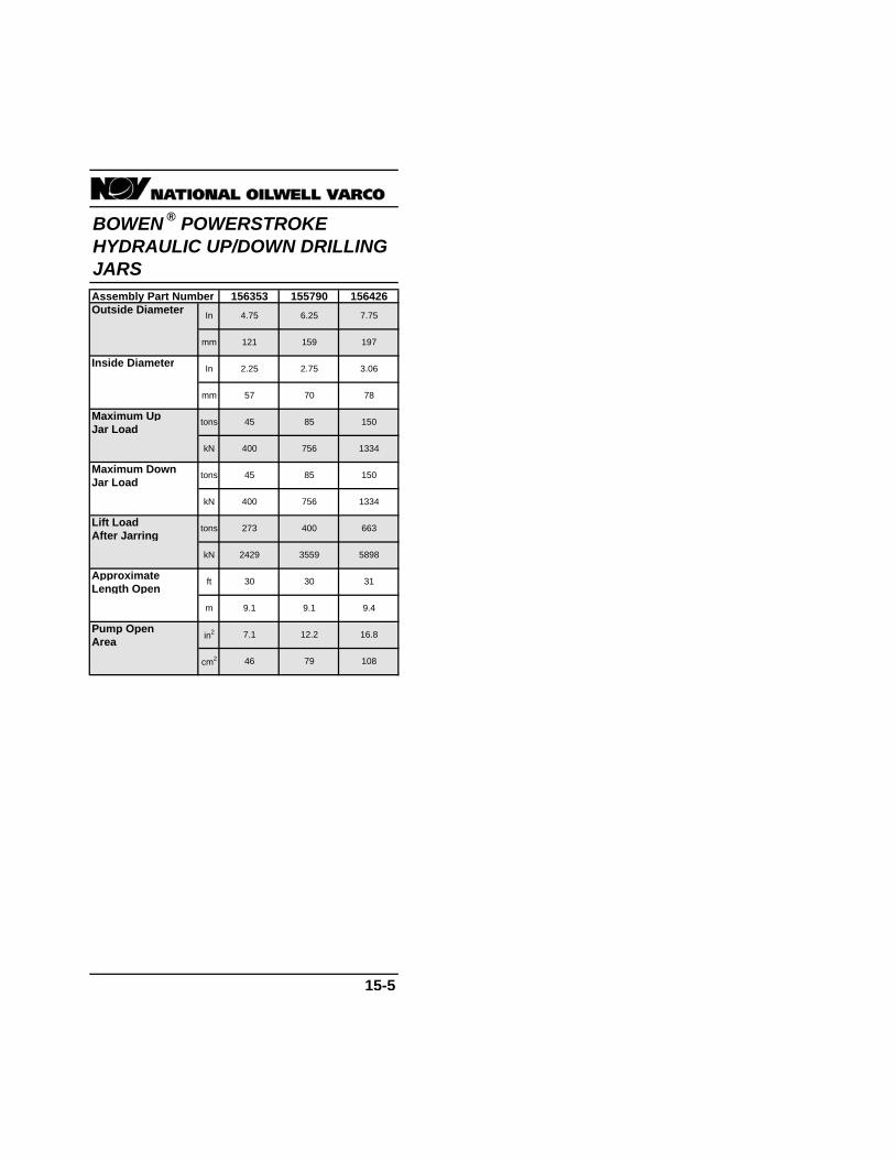
Assembly Part Number 156353 155790 156426Outside Diameter
Inside Diameter
Maximum UpJar Load
Maximum DownJar Load
Lift LoadAfter Jarring
ApproximateLength Open
Pump OpenArea
15-5
197
kN
mm
tons 150
400 756 1334
7.756.25
787057
45 85
mm
3.062.752.25In
159121
4.75In
tons
tons 273 400
45 85
kN 400 756
663
kN 2429 3559 5898
9.1 9.4
30 31ft 30
cm2 46
in2 7.1
m 9.1
16.812.2
79 108
BOWEN ® POWERSTROKE HYDRAULIC UP/DOWN DRILLING JARS
150
1334

GRIFFITH ® SHOCK TOOLS GRIFFITH ® SHOCK TOOLS
SERIES 155 146 150 147 154 SERIES 148 160 139 151 138Nominal Size Nominal Size(+API Drill (+API DrillCollar Tolerance) Collar Tolerance)
Max Recommended Max RecommendedHole Diameter Hole Diameter(Hole Openers Not (Hole Openers NotRecommended) Recommended)Inside Diameter Inside Diameter
Length Length
Weight Weight
Axial Load To Axial Load ToFully Compress Fully CompressTool Tool
Tensile Load Tensile LoadAt Yield At Yield
Maximum MaximumTorsional Load Torsional Load
Pump Open Pump OpenArea Area
Spring Rate Spring Rate
Opening Travel In 1.00 1.75 1.75 1.75 1.75 Opening Travel In 1.75 1.75 1.75 3.30 3.30mm 25 44 44 44 44 mm 44 44 44 84 84
Closing Travel In 2.50 2.90 2.90 3.00 3.00 Closing Travel In 3.60 4.00 3.20 4.00 4.00mm 64 74 74 76 76 mm 91 102 81 102 102
15-6 15-7
ft 9.40
2.87
12.50 9.409.40 9.40 9.40
m 2.87 3.81 2.872.87 2.87
25000 25000
248 266
in2 23.80
cm2 154
4400 4400
lb/in 35000 31000 35000
N/mm 6100 5400 6100
198 198
30.70 30.70
109000 157000
148000 213000
38.50 41.30
Nm 107000 107000 156000
lb-ft 79000 79000 115000
537000 463000
lbs 770000
daN 342000 388000 379000
872000 853000
100000 100000
44000 44000
1207000 1042000
daN 56000 56000 49000
lbs 125000 125000 110000
1000 1000
lbs 1200
kg 540 730 680
1600 1500
2.81 2.81
71 71
2200 2300
10.80 10.80
3.29 3.29
mm 64 70 71
In 2.50 2.75 2.81
17.50 17.50
mm 311 311 349 445 445
In 12.25 12.25 13.75
10.00
mm 203 203 229 241 254
8.00 8.00 9.00 9.50
35000 35000
593000
930
420
2.25 2.25
6100 6100
17.70
N/mm 5100 6100 6100
lb/in 29000 35000 35000
17.70
cm2 71 103 103 114 114
in2 11.00 15.90 15.90
54000 54000
73000 73000Nm 23000 56000 68000
lb-ft 17000 41000 50000
555000 593000
daN 169000 247000 247000 264000 264000
lbs 380000 555000
100000
daN 330000 440000 44000 44000 44000
lbs 74000 100000 100000
800 850
100000
390kg 170 330 360
ft
lbs 375 720
8.50 9.40
m 2.59 2.87
57
In 2.00 2.00 2.00
51 51 51 57
6.75In
222222216216171mm
8.758.75
In
mm
4.75In
178171165159
8.508.50
7.006.75
121mm
6.506.25

GRIFFITH ® SHOCK TOOLS
SERIES 157 143 113Nominal Size(+API DrillCollar Tolerance)
Max RecommendedHole Diameter(Hole Openers NotRecommended)Inside Diameter
Length
Weight
Axial Load ToFully CompressTool
Tensile LoadAt Yield
MaximumTorsional Load
Pump OpenArea
Spring Rate
Opening Travel In 2.50 2.50 2.00mm 64 64 51
Closing Travel In 7.00 7.00 7.00mm 178 178 178
15-8
lb/in 15000
N/mm 2600 2600 3900
15000 22000
cm2 71 76 81
in2 11.00 11.80 12.60
lb-ft 187000
Nm 254000 331000 542000
244000 400000
daN 359000 595000 830000
lbs 808000 1337000 1865000
lbs 100000
daN 44000 44000 62000
100000 140000
kg 1500 1500 2400
lbs 3200 3400 5200
ft 14.00
m 4.27 3.72 4.57
12.20 15.00
2.81 3.00
mm 71 71 76
445 660
17.50 26.00
12.00 14.00
mm 279 305 356
In 11.00
mm 445
In 17.50
In 2.81


