TeSys range provide you greater simplicity, compactness, openness and flexibility ... so many enhancements and new items to aid your productivity. Accurate and reliable control of motors Increase your productivity, with our solutions which help to simplify set-up. Motor starters p Ready-to-use component combinations, designed to work together in perfect harmony. p Safe operation and level of coordination guaranteed by a major manufacturer. Power circuit control p A wide range of components. p Solutions for a variety of power control applications: heating, changeover contactor pairs, resistive loads, upstream protection. Motor control
Transcript
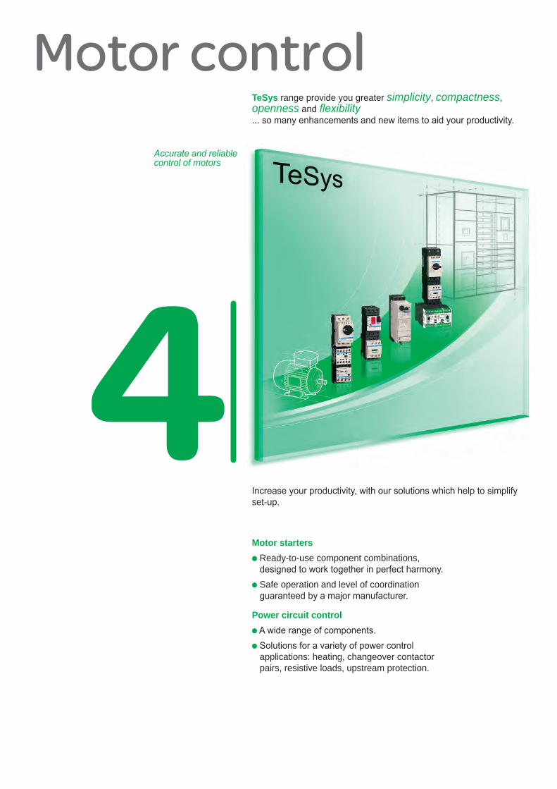
TeSys range provide you greater simplicity, compactness, openness and fl exibility... so many enhancements and new items to aid your productivity.
Accurate and reliable control of motors
Increase your productivity, with our solutions which help to simplify set-up.
Motor startersp Ready-to-use component combinations,
designed to work together in perfect harmony.p Safe operation and level of coordination
guaranteed by a major manufacturer.
Power circuit controlp A wide range of components.p Solutions for a variety of power control
With open communication across CANopen, Profi bus DP, Modbus, AS-interface, Advantys STB, DeviceNet and Ethernet networks, TeSys U has openness in mind.
TeSys Motor startersup to 65 A
The newTeSys GV3Type E Starters,LC1D 40/50/65contactors, LRD3thermal relays are equiped with the new terminal block:
Long lasting connection quality. Schneider Electricpatented technology.
ContentsNew
EverLink
TeSys TMotor management system
TeSys T is an advanced motor management and protection system. It is able to guard against all motor malfunctions: overload, current peak, excessive consumption, etc.
TeSys protected
11
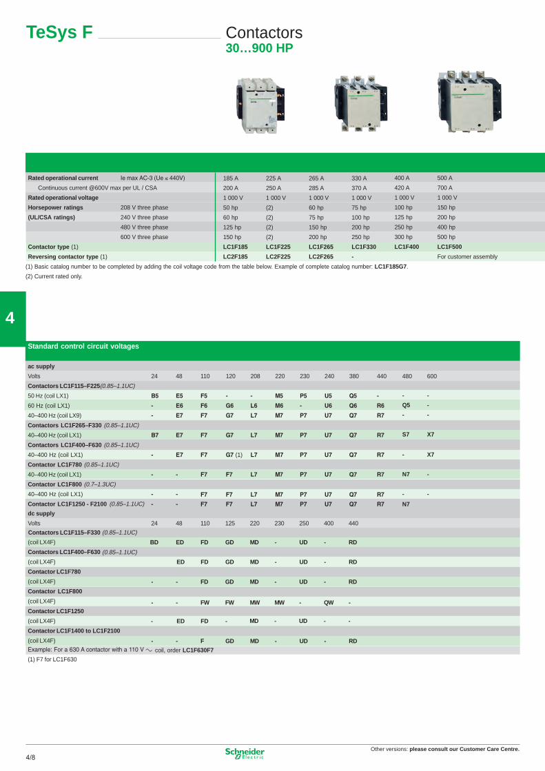
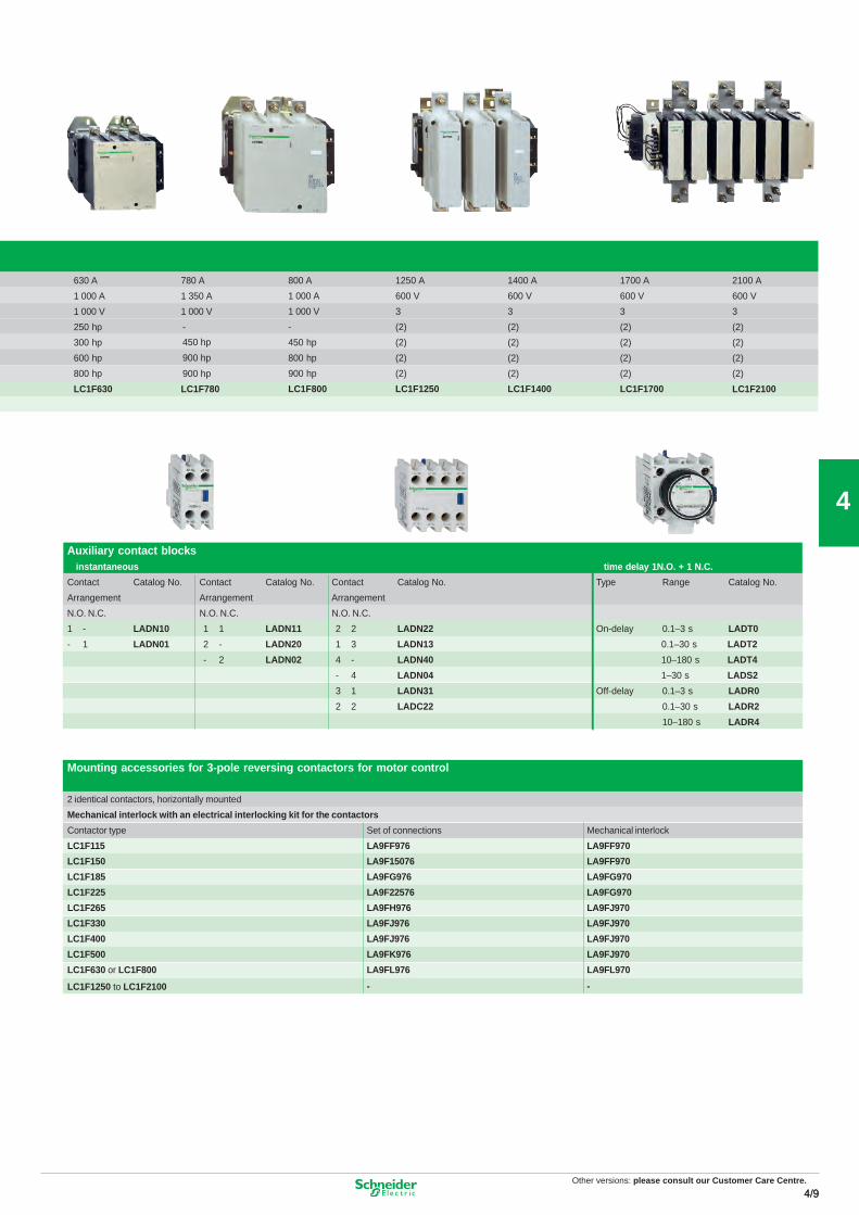
Motor control componentsTeSys contactors .............................................................. 4/2 to 4/11p Contactors, TeSys K, D, F, Bp Variable composition contactors, TeSys CV
TeSys protection components ..................................... 4/12 to 4/25p Thermal overload relays, LR2K, LDRp Electronic thermal overload relays, LR9p Electronic protection relays, LT3p Motor management system, TeSys T p Manual motor starters, group & type E, GV2, GV3, GV7 p Motor disconnect switches, Variop Fuse carriers, DK, LS1p Disconnect switches, fusible & non-fused, GS, LK
TeSys starters ............................................................... 4/26 to 4/31p Type E self protected starter, TeSys U p Controller, TeSys U p Enclosed motor starters, “Instakits”
TeSys installation system ............................................. 4/32 to 4/33 p For motor starter components with spring
terminals, TeSys Quickfi t technology
TeSys Application Information ..................................... 4/34 to 4/35 p Group motor, Type E, Elevator ratings,
Safety applications
Components for power control applications .................................. 4/36 to 4/42p Heating, 3 and 4 pole resistive loads
changeover contactor pairs, TeSys K, D, F, Bp Industrial control relays, CA2/3/4K, CAD
Other versions: please consult our Customer Care Centre.4/1
TeSys range provide you greater simplicity, compactness, openness and fl exibility... so many enhancements and new items to aid your productivity.
Accurate and reliable control of motors
Increase your productivity, with our solutions which help to simplify set-up.
Motor startersp Ready-to-use component combinations,
designed to work together in perfect harmony.p Safe operation and level of coordination
guaranteed by a major manufacturer.
Power circuit controlp A wide range of components.p Solutions for a variety of power control
With open communication across CANopen, Profi bus DP, Modbus, AS-interface, Advantys STB, DeviceNet and Ethernet networks, TeSys U has openness in mind.
TeSys Motor startersup to 65 A
The newTeSys GV3Type E Starters,LC1D 40/50/65contactors, LRD3thermal relays are equiped with the new terminal block:
Long lasting connection quality. Schneider Electricpatented technology.
ContentsNew
EverLink
TeSys TMotor management system
TeSys T is an advanced motor management and protection system. It is able to guard against all motor malfunctions: overload, current peak, excessive consumption, etc.
TeSys protected
11
Motor control componentsTeSys contactors .............................................................. 4/2 to 4/11p Contactors, TeSys K, D, F, Bp Variable composition contactors, TeSys CV
TeSys protection components ..................................... 4/12 to 4/25p Thermal overload relays, LR2K, LDRp Electronic thermal overload relays, LR9p Electronic protection relays, LT3p Motor management system, TeSys T p Manual motor starters, group & type E, GV2, GV3, GV7 p Motor disconnect switches, Variop Fuse carriers, DK, LS1p Disconnect switches, fusible & non-fused, GS, LK
TeSys starters ............................................................... 4/26 to 4/31p Type E self protected starter, TeSys U p Controller, TeSys U p Enclosed motor starters, “Instakits”
TeSys installation system ............................................. 4/32 to 4/33 p For motor starter components with spring
terminals, TeSys Quickfi t technology
TeSys Application Information ..................................... 4/34 to 4/35 p Group motor, Type E, Elevator ratings,
Safety applications
Components for power control applications .................................. 4/36 to 4/42p Heating, 3 and 4 pole resistive loads
changeover contactor pairs, TeSys K, D, F, Bp Industrial control relays, CA2/3/4K, CAD
TeSys UCommunication modules
With open communication across CANopen, Profi bus DP, Modbus, AS-interface, Advantys STB, DeviceNet and Ethernet networks, TeSys U has openness in mind.
TeSys Motor startersup to 65 A
The newTeSys GV3Type E Starters,LC1D 40/50/65contactors, LRD3thermal relays are equiped with the new terminal block:
Long lasting connection quality. Schneider Electricpatented technology.
ContentsNew
EverLink
TeSys TMotor management system
TeSys T is an advanced motor management and protection system. It is able to guard against all motor malfunctions: overload, current peak, excessive consumption, etc.
TeSys protected
11
Motor control componentsTeSys contactors .............................................................. 4/2 to 4/11p Contactors, TeSys K, D, F, Bp Variable composition contactors, TeSys CV
TeSys protection components ..................................... 4/12 to 4/25p Thermal overload relays, LR2K, LDRp Electronic thermal overload relays, LR9p Electronic protection relays, LT3p Motor management system, TeSys T p Manual motor starters, group & type E, GV2, GV3, GV7 p Motor disconnect switches, Variop Fuse carriers, DK, LS1p Disconnect switches, fusible & non-fused, GS, LK
TeSys starters ............................................................... 4/26 to 4/31p Type E self protected starter, TeSys U p Controller, TeSys U p Enclosed motor starters, “Instakits”
TeSys installation system ............................................. 4/32 to 4/33 p For motor starter components with spring
terminals, TeSys Quickfi t technology
TeSys Application Information ..................................... 4/34 to 4/35 p Group motor, Type E, Elevator ratings,
Safety applications
Components for power control applications .................................. 4/36 to 4/42p Heating, 3 and 4 pole resistive loads
changeover contactor pairs, TeSys K, D, F, Bp Industrial control relays, CA2/3/4K, CAD
Other versions: please consult our Customer Care Centre.4/2
4
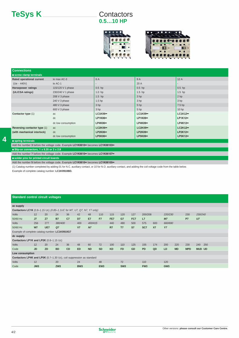
TeSys K Contactors0.5…10 HP
Connections� screw clamp terminals
Rated operational current A 21A 9A 63-CA xam eI
-A 02-1-CA eI)V044 - eU(
Horsepower ratings ph 5.0ph 5.0ph 5.0esahp 1 V 021/511
(UL/CSA ratings) ph 5.1ph 5.1ph 0.1esahp 1 V 042/032
ph 2ph 3ph 5.1esahp 3 V 802
ph 3ph 3ph 5.1esahp 3 V 042
ph 5.7ph 5ph 3esahp 3 V 084
ph 01ph 5ph 3esahp 3 V 006
Contactor type (1) ac LC1K06 ••21K1CL••90K1CL••
dc LP1K06•• LP1K09•• LP1K12••
dc low consumption LP4K06•• LP4K09•• LP4K12••
dc low consumption LP5K06•• LP5K09•• LP5K12••
Reversing contactor type (1) ac ••21K2CL••90K2CL••60K2CL
(with mechanical interlock) dc LP2K06••
� spring terminals
Add the number 3 before the voltage code. Example LC1K0610•• becomes LC1K06103••
� Slip-on connectors, 1 x 6.35 or 2 x 2.8
Add the number 7 before the voltage code. Example LC1K0610•• becomes LC1K06107••
� solder pins for printed circuit boards
Add the number 5 before the voltage code. Example LC1K0610•• becomes LC1K06105••
(1) Catalog number completed by adding 01 for N.C. auxiliary contact, or 10 for N.O. auxiliary contact, and adding the coil voltage code from the table below.
� for LC1, LP1-K, LP4 � for LC1, LP1-KContact arrangement 2N/O - 2N/C 1N/O 1N/C 4N/O 3N/O 1N/C 2N/C 2N/C 1N/O 3N/C - 4N/CCatalog number LA1-KN20 LA1-KN02 LA1-KN11 LA1-KN40 LA1-KN31 LA1-KN22 LA1-KN13 LA1-KN04� electronic time delay
Relay outputs, with common point changeover contact, a or c 24…48, 2 A maximumControl voltage 0.85…1.1UcMaximum switching capacity 250 VA or 150 WOperating temperature -10…+ 60°CReset time: 1.5 s for 0.5 s after the time delay periodType On-delayTiming range 1…30 sComposition 1 C/O (form C)Voltage a or c 24…48 V a 110…240Catalog number LA2-KT2E LA2-KT2U
Suppressor modulesFor LC1, LP1-KType Varistor (a and c) Diode (c) + zener RC (a)Voltage 12…24 V 32…48 V 50…129 V 130…250 V 12…24 V 32…48 V 220…250 VCatalog number LA4-KE1B LA4-KE1E LA4-KE1FC LA4-KE1UG LA4-KC1B LA4-KC1E LA4-KA1U
Other versions: Please consult our Customer Care Centre.
3
Other versions: please consult our Customer Care Centre.4/34/3
4
TeSys K Contactors0.5…10 HP
Connections� screw clamp terminals
Rated operational current A 21A 9A 63-CA xam eI
-A 02-1-CA eI)V044 - eU(
Horsepower ratings ph 5.0ph 5.0ph 5.0esahp 1 V 021/511
(UL/CSA ratings) ph 5.1ph 5.1ph 0.1esahp 1 V 042/032
ph 2ph 3ph 5.1esahp 3 V 802
ph 3ph 3ph 5.1esahp 3 V 042
ph 5.7ph 5ph 3esahp 3 V 084
ph 01ph 5ph 3esahp 3 V 006
Contactor type (1) ac LC1K06 ••21K1CL••90K1CL••
dc LP1K06•• LP1K09•• LP1K12••
dc low consumption LP4K06•• LP4K09•• LP4K12••
dc low consumption LP5K06•• LP5K09•• LP5K12••
Reversing contactor type (1) ac ••21K2CL••90K2CL••60K2CL
(with mechanical interlock) dc LP2K06••
� spring terminals
Add the number 3 before the voltage code. Example LC1K0610•• becomes LC1K06103••
� Slip-on connectors, 1 x 6.35 or 2 x 2.8
Add the number 7 before the voltage code. Example LC1K0610•• becomes LC1K06107••
� solder pins for printed circuit boards
Add the number 5 before the voltage code. Example LC1K0610•• becomes LC1K06105••
(1) Catalog number completed by adding 01 for N.C. auxiliary contact, or 10 for N.O. auxiliary contact, and adding the coil voltage code from the table below.
� for LC1, LP1-K, LP4 � for LC1, LP1-KContact arrangement 2N/O - 2N/C 1N/O 1N/C 4N/O 3N/O 1N/C 2N/C 2N/C 1N/O 3N/C - 4N/CCatalog number LA1-KN20 LA1-KN02 LA1-KN11 LA1-KN40 LA1-KN31 LA1-KN22 LA1-KN13 LA1-KN04� electronic time delay
Relay outputs, with common point changeover contact, a or c 24…48, 2 A maximumControl voltage 0.85…1.1UcMaximum switching capacity 250 VA or 150 WOperating temperature -10…+ 60°CReset time: 1.5 s for 0.5 s after the time delay periodType On-delayTiming range 1…30 sComposition 1 C/O (form C)Voltage a or c 24…48 V a 110…240Catalog number LA2-KT2E LA2-KT2U
Suppressor modulesFor LC1, LP1-KType Varistor (a and c) Diode (c) + zener RC (a)Voltage 12…24 V 32…48 V 50…129 V 130…250 V 12…24 V 32…48 V 220…250 VCatalog number LA4-KE1B LA4-KE1E LA4-KE1FC LA4-KE1UG LA4-KC1B LA4-KC1E LA4-KA1U
Other versions: Please consult our Customer Care Centre.
3
Other versions: please consult our Customer Care Centre.4/4
4
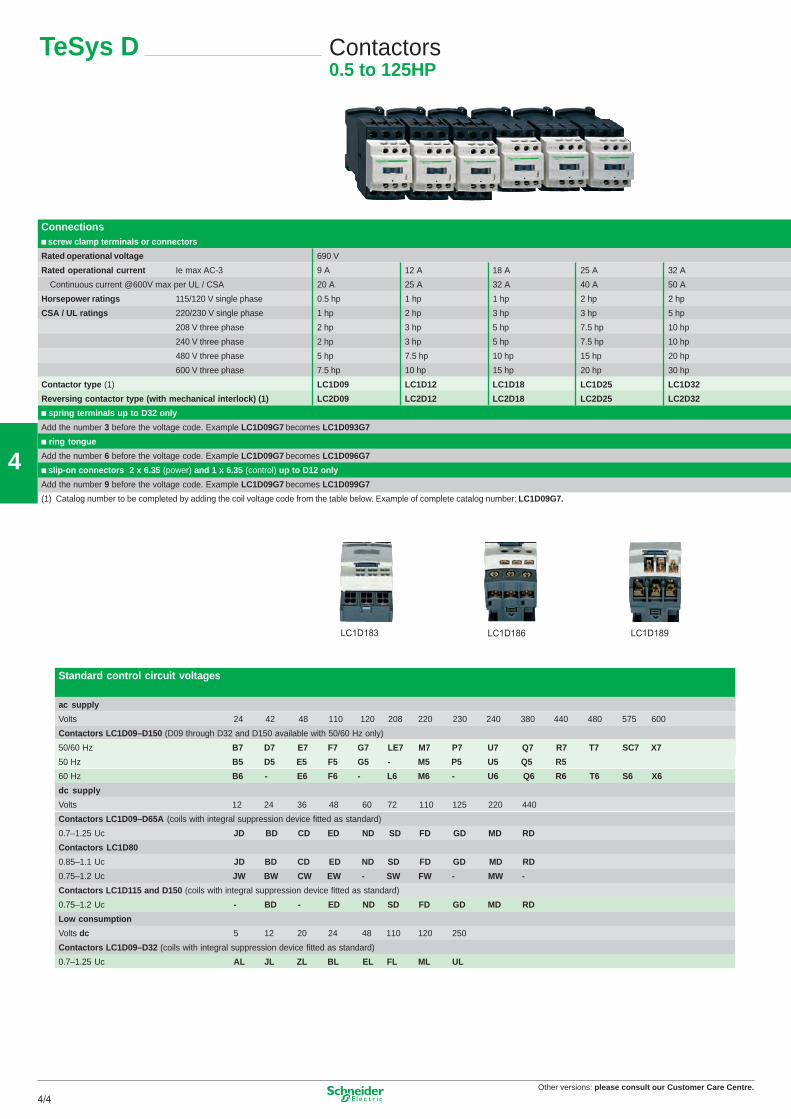
Connections� screw clamp terminals or connectors
Rated operational voltage 690 V
Rated operational current A 23A 52A 81A 21A 93-CA xam eI
A 05A 04A 23A 52A 02Continuous current @600V max per UL / CSA
Horsepower ratings 115/120 V single phase 0.5 hp 1 hp 1 hp 2 hp 2 hp
CSA / UL ratings 220/230 V single phase 1 hp 2 hp 3 hp 3 hp 5 hp
208 V three phase 2 hp 3 hp 5 hp 7.5 hp 10 hp
240 V three phase 2 hp 3 hp 5 hp 7.5 hp 10 hp
480 V three phase 5 hp 7.5 hp 10 hp 15 hp 20 hp
600 V three phase 7.5 hp 10 hp 15 hp 20 hp 30 hp
Contactor type (1) LC1D09 LC1D12 LC1D18 LC1D25 LC1D32
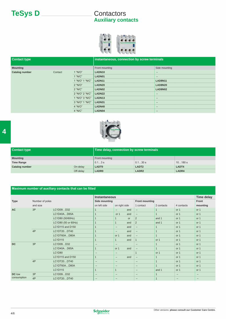
Contact type Time delay, connection by screw terminals
Mounting Front mountingTime Range 0.1…3 s 0.1…30 s 10…180 sCatalog number On-delay LADT0 LADT2 LADT4
Off-delay LADR0 LADR2 LADR4
Maximum number of auxiliary contacts that can be fi tted
Instantaneous Time delayType Number of poles Side mounting Front mounting Front
and size on left side on right side 1 contact 2 contacts 4 contacts mountingAC 3P LC1D09…D32 1 – and – 1 or 1 or 1
LC1D40A…D65A 1 or 1 and – 1 or 1 or 1LC1D80 (50/60Hz) 1 1 or 2 and 1 or 1 or 1LC1D80 (50 or 60Hz) 1 1 and 2 and 1 or 1 or 1LC1D115 and D150 1 – and – 1 or 1 or 1
4P LC1DT20…DT40 1 – and – 1 or 1 or 1LC1DT60A…D80A 1 or 1 and – 1 or 1 or 1LC1D115 1 1 and 1 or 1 or 1 or 1
DC 3P LC1D09…D32 – – – 1 or 1 or 1LC1D40A…D65A 1 or 1 and – 1 or 1 or 1LC1D80 – – 1 or 1 or 1 or 1LC1D115 and D150 1 – and – 1 or 1 or 1
4P LC1DT20…DT40 – – – 1 or 1 or 1LC1DT60A…D80A – – – 1 or 1 or 1LC1D115 1 1 – and 1 or 1 or 1
* Basic reference to be completed by adding the coil voltage, followed by the instantaneous contact configuration.
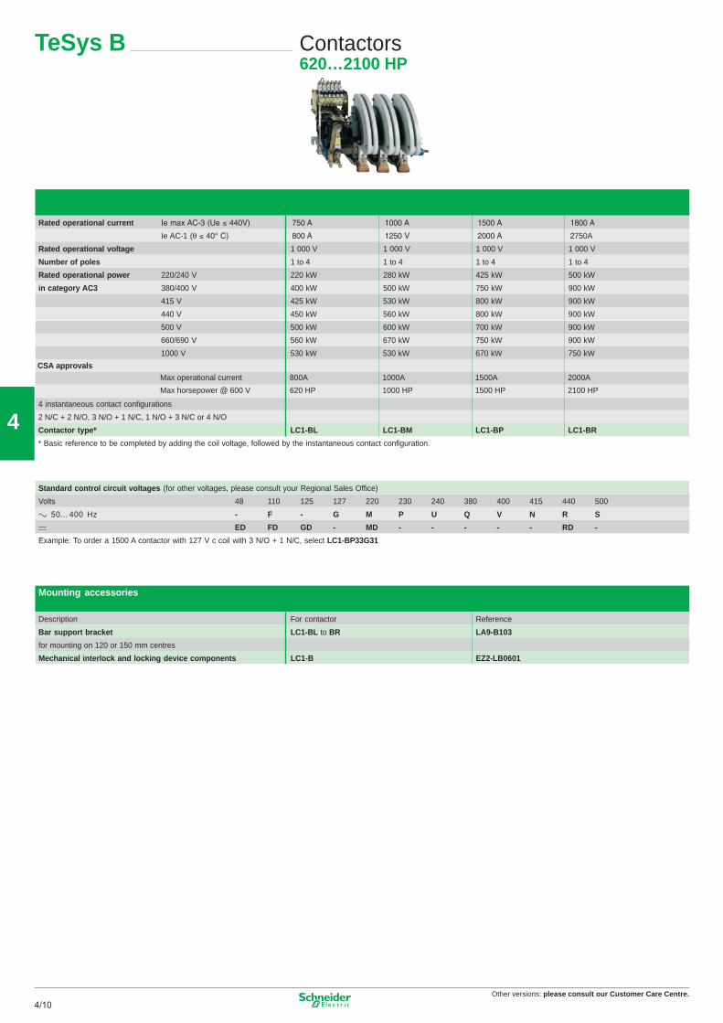
CSA approvalsMax operational current 800A 1000A 1500A 2000A
Max horsepower @ 600 V 620 HP 1000 HP 1500 HP 2100 HP
10
Reference to compiled by the customer
Contactor type, according to required use
a supply 690 V, c supply 220 V/pole CV1-B
a supply 1000 V, c supply 440 V/pole CV3-BContactor rating CV1: 80 A CV3: 80 A F
CV1: 200 A CV3: 170 A GCV1: 300 A CV3: 250 A HCV1: 470 A CV3: 320 A JCV1: 630 A CV3: 500 A KCV1: 1000 A L
Number of poles (PN1 main poles for CV1 and PA3 main poles for CV3)Normally Open main poles 1 N/O 1
2 N/O 23 N/O 34 N/O 45 N/O 5
Normally Closed main poles 1 N/C 12 N/C 23 N/C 3
No main poles 0 Z 0 ZOperational current 10 A E E
20 A N N40 A P P80 A F F125 A R R170 A W W200 A G G250 A S S300 A H H320 A T T470 A J J500 A V V630 A K K1000 A L L
Control circuit voltage 48 V E110 V F120 V K208 V L220 V M 230 V P240 V U380 V Q400 V V440 V R
Operating frequency 50 Hz 560 Hz 650/60 Hz 7
c D
c + economy resistor RInstantaneous auxiliary contactsNormally Open 1 N/O 1
2 N/O 23 N/O 34 N/O 4
Normally Closed 1 N/C 12 N/C 23 N/C 34 N/C 4
Without instantaneous contact 0 0On-delay 1 C/O JOff-delay 1 C/O NExample 1/ for single-phase capacitor switching: 400 V - 80 A - 1 N/O pole - Control circuit 220 V / 50 Hz, 1 N/O and 1 1N/C auxiliary contacts: CV1-BF1F0ZM511.2/ for heating circuits, d.c. supply 800 V - 150 A - 2 N/O poles - Control circuit 48 V c , 1 N/O + 1 N/O On-delay auxiliary contacts: CV3-BG2W0ZED10J
TeSys CV1-B, CV3-B
Contactors variable compositionCV1-B : 80…1000 A, CV3-B : 80…500 A
Other versions: Please consult our Customer Care Centre.
11
Other versions: please consult our Customer Care Centre.4/114/11
4
TeSys B Contactors620…2100 HP
Standard control circuit voltages (for other voltages, please consult your Regional Sales Office)
00504451400408304203202272152101184stloV
400 Hz - F - G M P U Q V N R S
ED FD GD - MD - - - - - RD -
Example: To order a 1500 A contactor with 127 V c coil with 3 N/O + 1 N/C, select LC1-BP33G31
Mounting accessories
Description ecnerefeRrotcatnoc roF
LB-1CLtekcarb troppus raB to 301B-9ALRB
for mounting on 120 or 150 mm centres
Mechanical interlock and locking device components 1060BL-2ZEB-1CL
Rated operational current
Ie AC-1 (θ 750A
Rated operational voltage 1 000 V 1 000 V 1 000 V 1 000 V
Number of poles 1 to 4 1 to 4 1 to 4 1 to 4
Rated operational power Wk 005Wk 524Wk 082Wk 022V 042/022
* Basic reference to be completed by adding the coil voltage, followed by the instantaneous contact configuration.
CSA approvalsMax operational current 800A 1000A 1500A 2000A
Max horsepower @ 600 V 620 HP 1000 HP 1500 HP 2100 HP
10
Reference to compiled by the customer
Contactor type, according to required use
a supply 690 V, c supply 220 V/pole CV1-B
a supply 1000 V, c supply 440 V/pole CV3-BContactor rating CV1: 80 A CV3: 80 A F
CV1: 200 A CV3: 170 A GCV1: 300 A CV3: 250 A HCV1: 470 A CV3: 320 A JCV1: 630 A CV3: 500 A KCV1: 1000 A L
Number of poles (PN1 main poles for CV1 and PA3 main poles for CV3)Normally Open main poles 1 N/O 1
2 N/O 23 N/O 34 N/O 45 N/O 5
Normally Closed main poles 1 N/C 12 N/C 23 N/C 3
No main poles 0 Z 0 ZOperational current 10 A E E
20 A N N40 A P P80 A F F125 A R R170 A W W200 A G G250 A S S300 A H H320 A T T470 A J J500 A V V630 A K K1000 A L L
Control circuit voltage 48 V E110 V F120 V K208 V L220 V M 230 V P240 V U380 V Q400 V V440 V R
Operating frequency 50 Hz 560 Hz 650/60 Hz 7
c D
c + economy resistor RInstantaneous auxiliary contactsNormally Open 1 N/O 1
2 N/O 23 N/O 34 N/O 4
Normally Closed 1 N/C 12 N/C 23 N/C 34 N/C 4
Without instantaneous contact 0 0On-delay 1 C/O JOff-delay 1 C/O NExample 1/ for single-phase capacitor switching: 400 V - 80 A - 1 N/O pole - Control circuit 220 V / 50 Hz, 1 N/O and 1 1N/C auxiliary contacts: CV1-BF1F0ZM511.2/ for heating circuits, d.c. supply 800 V - 150 A - 2 N/O poles - Control circuit 48 V c , 1 N/O + 1 N/O On-delay auxiliary contacts: CV3-BG2W0ZED10J
TeSys CV1-B, CV3-B
Contactors variable compositionCV1-B : 80…1000 A, CV3-B : 80…500 A
Other versions: Please consult our Customer Care Centre.
11
Other versions: please consult our Customer Care Centre.4/12
4
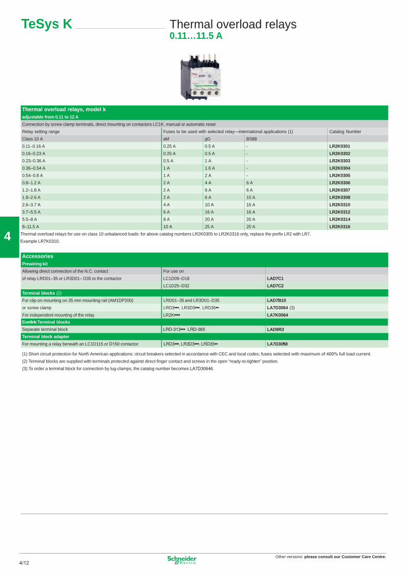
TeSys K Thermal overload relays0.11…11.5 A
Thermal overload relays, model kadjustable from 0.11 to 12 A
Connection by screw clamp terminals, direct mounting on contactors LC1K, manual or automatic reset
yaler detceles htiw desu eb ot sesuFegnar gnittes yaleR —international applications (1) Catalog Number
88SBGgMaA 01 ssalC
-A 5.0A 52.0A 61.0–11.0 LR2K0301
-A 5.0A 52.0A 32.0–61.0 LR2K0302
-A 1A 5.0A 63.0–32.0 LR2K0303
-A 6.1A 1A 45.0–63.0 LR2K0304
-A 2A 1A 8.0–45.0 LR2K0305
A 6A 4A 2A 2.1–8.0 LR2K0306
A 6A 6A 2A 8.1–2.1 LR2K0307
A 01A 6A 2A 6.2–8.1 LR2K0308
A 61A 01A 4A 7.3–6.2 LR2K0310
A 61A 61A 6A 5.5–7.3 LR2K0312
A 02A 02A 8A 8–5.5 LR2K0314
A 02A 52A 01A 5.11–8 LR2K0316
Thermal overload relays for use on class 10 unbalanced loads: for above catalog numbers LR2K0305 to LR2K0316 only, replace the prefix LR2 with LR7.
Example LR7K0310.
AccessoriesPrewiring kit
no esu roFtcatnoc .C.N eht fo noitcennoc tcerid gniwollA
of relay LRD01–35 or LR3D01– D35 to the contactor LC1D09–D18 LAD7C1
LC1D25–D32 LAD7C2
Terminal blocks (2)
For clip-on mounting on 35 mm mounting rail (AM1DP200) LRD01–35 and LR3D01–D35 LAD7B10
For mounting a relay beneath an LC1D115 or D150 contactor LRD3•••, LR3D3•••, LRD35•• LA7D3058•
(1) Short circuit protection for North American applications: circuit breakers selected in accordance with CEC and local codes; fuses selected with maximum of 400% full load current.
(2) Terminal blocks are supplied with terminals protected against direct finger contact and screws in the open “ready-to-tighten” position.
(3) To order a terminal block for connection by lug-clamps, the catalog number becomes LA7D30646.
Everlink Terminal blocks
12
Other versions: please consult our Customer Care Centre.4/134/13
4
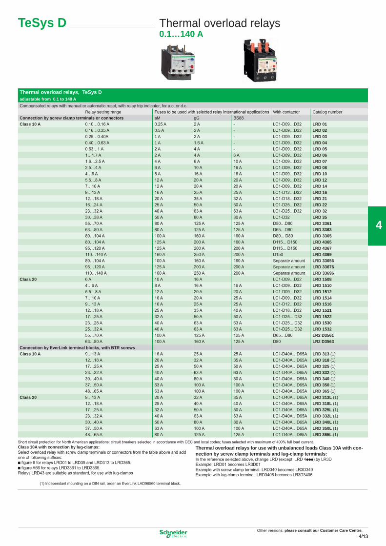
TeSys D Thermal overload relays0.1…140 A
Thermal overload relays, TeSys Dadjustable from 0.1 to 140 ACompensated relays with manual or automatic reset, with relay trip indicator, for a.c. or d.c.
Relay setting range Fuses to be used with selected relay international applications With contactor Catalog numberConnection by screw clamp terminals or connectors aM gG BS88Class 10 A 0.10…0.16 A 0.25 A 2 A - LC1-D09…D32 LRD 01
0.16…0.25 A 0.5 A 2 A - LC1-D09…D32 LRD 020.25…0.40A 1 A 2 A - LC1-D09…D32 LRD 030.40…0.63 A 1 A 1.6 A - LC1-D09…D32 LRD 040,63…1 A 2 A 4 A - LC1-D09…D32 LRD 051…1.7 A 2 A 4 A 6 A LC1-D09…D32 LRD 061.6…2.5 A 4 A 6 A 10 A LC1-D09…D32 LRD 072.5…4 A 6 A 10 A 16 A LC1-D09…D32 LRD 084…6 A 8 A 16 A 16 A LC1-D09…D32 LRD 105.5…8 A 12 A 20 A 20 A LC1-D09…D32 LRD 127…10 A 12 A 20 A 20 A LC1-D09…D32 LRD 149…13 A 16 A 25 A 25 A LC1-D12…D32 LRD 1612…18 A 20 A 35 A 32 A LC1-D18…D32 LRD 2116…24 A 25 A 50 A 50 A LC1-D25…D32 LRD 2223…32 A 40 A 63 A 63 A LC1-D25…D32 LRD 3230…38 A 50 A 80 A 80 A LC1-D32 LRD 3555…70 A 80 A 125 A 125 A D50…D80 LRD 336163…80 A 80 A 125 A 125 A D65…D80 LRD 336380…104 A 100 A 160 A 160 A D80... D80 LRD 336580…104 A 125 A 200 A 160 A D115... D150 LRD 436595…120 A 125 A 200 A 200 A D115... D150 LRD 4367110…140 A 160 A 250 A 200 A D150 LRD 436980…104 A 100 A 160 A 160 A Separate amount LRD 3365695…120 A 125 A 200 A 200 A Separate amount LRD 33676110…140 A 160 A 250 A 200 A Separate amount LRD 33696
Class 20 6 A 10 A 16 A LC1-D09…D32 LRD 15084…6 A 8 A 16 A 16 A LC1-D09…D32 LRD 15105.5…8 A 12 A 20 A 20 A LC1-D09…D32 LRD 15127…10 A 16 A 20 A 25 A LC1-D09…D32 LRD 15149…13 A 16 A 25 A 25 A LC1-D12…D32 LRD 151612…18 A 25 A 35 A 40 A LC1-D18…D32 LRD 152117…25 A 32 A 50 A 50 A LC1-D25... D32 LRD 152223…28 A 40 A 63 A 63 A LC1-D25... D32 LRD 153025…32 A 40 A 63 A 63 A LC1-D25... D32 LRD 153255…70 A 100 A 125 A 125 A D65…D80 LR2 D3561 63…80 A 100 A 160 A 125 A D80 LR2 D3563
Connection by EverLink terminal blocks, with BTR screwsClass 10 A 9…13 A 16 A 25 A 25 A LC1-D40A…D65A LRD 313 (1)
12…18 A 20 A 32 A 35 A LC1-D40A…D65A LRD 318 (1)17…25 A 25 A 50 A 50 A LC1-D40A…D65A LRD 325 (1)23…32 A 40 A 63 A 63 A LC1-D40A…D65A LRD 332 (1)30…40 A 40 A 80 A 80 A LC1-D40A…D65A LRD 340 (1)37…50 A 63 A 100 A 100 A LC1-D40A…D65A LRD 350 (1)48…65 A 63 A 100 A 100 A LC1-D40A…D65A LRD 365 (1)
Class 20 9…13 A 20 A 32 A 35 A LC1-D40A…D65A LRD 313L (1)12…18 A 25 A 40 A 40 A LC1-D40A…D65A LRD 318L (1)17…25 A 32 A 50 A 50 A LC1-D40A…D65A LRD 325L (1)23…32 A 40 A 63 A 63 A LC1-D40A…D65A LRD 332L (1)30…40 A 50 A 80 A 80 A LC1-D40A…D65A LRD 340L (1)37…50 A 63 A 100 A 100 A LC1-D40A…D65A LRD 350L (1)48…65 A 80 A 125 A 125 A LC1-D40A…D65A LRD 365L (1)
Class 10A with connection by lug-clamps: Select overload relay with screw clamp terminals or connectors from the table above and add one of following suffixes:b fi gure 6 for relays LRD01 to LRD35 and LRD313 to LRD365.b fi gure A66 for relays LRD3361 to LRD3365.Relays LRD43 are suitable as standard, for use with lug-clamps
Thermal overload relays for use with unbalanced loads Class 10A with con-nection by screw clamp terminals and lug-clamp terminals:In the reference selected above, change LRD (except LRD 4ppp) by LR3DExample: LRD01 becomes LR3D01Example with screw clamp terminal: LRD340 becomes LR3D340Example with lug-clamp terminal: LRD3406 becomes LR3D3406
(1) Independant mounting on a DIN rail, order an EverLink LAD96560 terminal block.
Short circuit protection for North American applications: circuit breakers selected in accordance with CEC and local codes; fuses selected with maximum of 400% full load current.
Other versions: Please consult our Customer Care Centre.
13
Other versions: please consult our Customer Care Centre.4/14
4
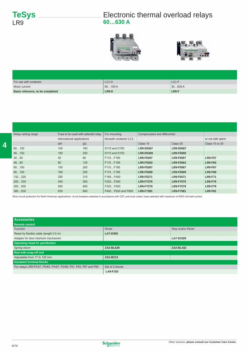
For use with contactor LC1-D LC1-FMotor current 60…150 A 30…630 ABasic reference, to be completed LR9-D LR9-F
Relay setting range Fuse to be used with selected relay For mounting Compensated and differentialinternational applications beneath contactor LC1- or not with alarmaM gG Class 10 Class 20 Class 10 or 20
AccessoriesRemote controlFunction Reset Stop and/or ResetReset by fl exible cable (length 0.5 m) LA7-D305Adapter for door interlock mechanism LA7-D1020Operating head for pushbutton Spring return ZA2-BL639 ZA2-BL432Rod with snap-off endAdjustable from 17 to 120 mm ZA2-BZ13Insulated terminal blocksFor relays LR9-F5•57, F5•63, F5•67, F5•69, F57, F63, F67 and F69 Set of 2 blocks
LA9-F103
TeSys LR9
Electronic thermal overload relays60…630 A
Short circuit protection for North American applications: circuit breakers selected in accordance with CEC and local codes; fuses selected with maximum of 400% full load current.
14
Other versions: please consult our Customer Care Centre.4/154/15
4
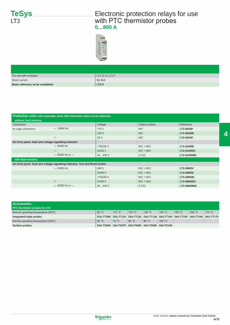
TeSys LT3
Electronic protection relays for use with PTC thermistor probes0…800 A
For use with contactor LC1-D or LC1-FMotor current No limitBasic reference, to be completed LT3-S
Protection units with automatic reset with thermistor short-circuit detection� without fault memoryConnection Voltage Output contact Referenceby cage connectors a 50/60 Hz 115 V N/C LT3-SE00F
230 V N/C LT3-SE00Mc 24 V N/C LT3-SE00F
On front panel: fault and voltage signalling indicatora 50/60 Hz 115/230 V N/C + N/O LT3-SA00Mc 24/48 V N/C + N/O LT3-SA00EDa 50/60 Hz or c 24…230 V 2 C/O LT3-SA00MW
� with fault memoryOn front panel: fault and voltage signalling indicator, Test and Reset button
a 50/60 Hz 400 V N/C + N/O LT3-SM00V24/48 V N/C + N/O LT3-SM00E115/230 V N/C + N/O LT3-SM00M
c 24/48 V N/C + N/O LT3-SM00EDa 50/60 Hz or c 24…230 V 2 C/O LT3-SM00MW
AccessoriesPTC thermistor probes for LT3Normal operating temperature (NOT) 90 °C 110 °C 120 °C 130 °C 140 °C 150 °C 160 °C 170 °CIntegrated triple probes DA1-TT090 DA1-TT110 DA1-TT120 DA1-TT130 DA1-TT140 DA1-TT150 DA1-TT160 DA1-TT170Normal operating temperature (NOT) 60 °C 70 °C 80 °C 90 °C 100 °CSurface probes DA1-TS060 DA1-TS070 DA1-TS080 DA1-TS090 DA1-TS100
Other versions: Please consult our Customer Care Centre.
15
Other versions: please consult our Customer Care Centre.4/16
4
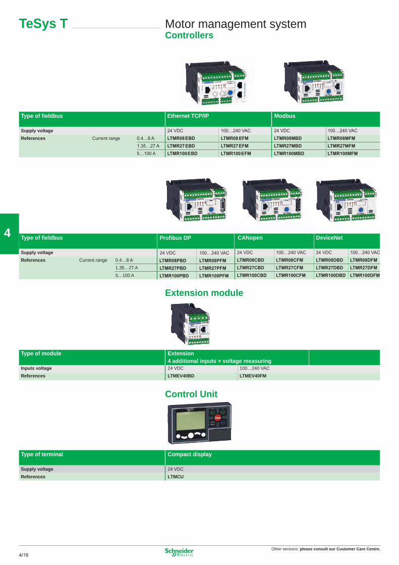
Motor management systemControllers
TeSys T
Type of fi eldbus Ethernet TCP/IP Modbus
Supply voltageReferences Current range
Type of fi eldbus CANopen DeviceNet
Supply voltageReferences Current range 0.4…8 A
1.35…27 A5…100 A
Extension module
Type of module Extension4 additional inputs + voltage measuring
Inputs voltage 24 VDC 100…240 VACReferences LTMEV40BD LTMEV40FM
Control Unit
Type of terminal Compact display
Supply voltage 24 VDCReferences LTMCU
Profibus DP
16
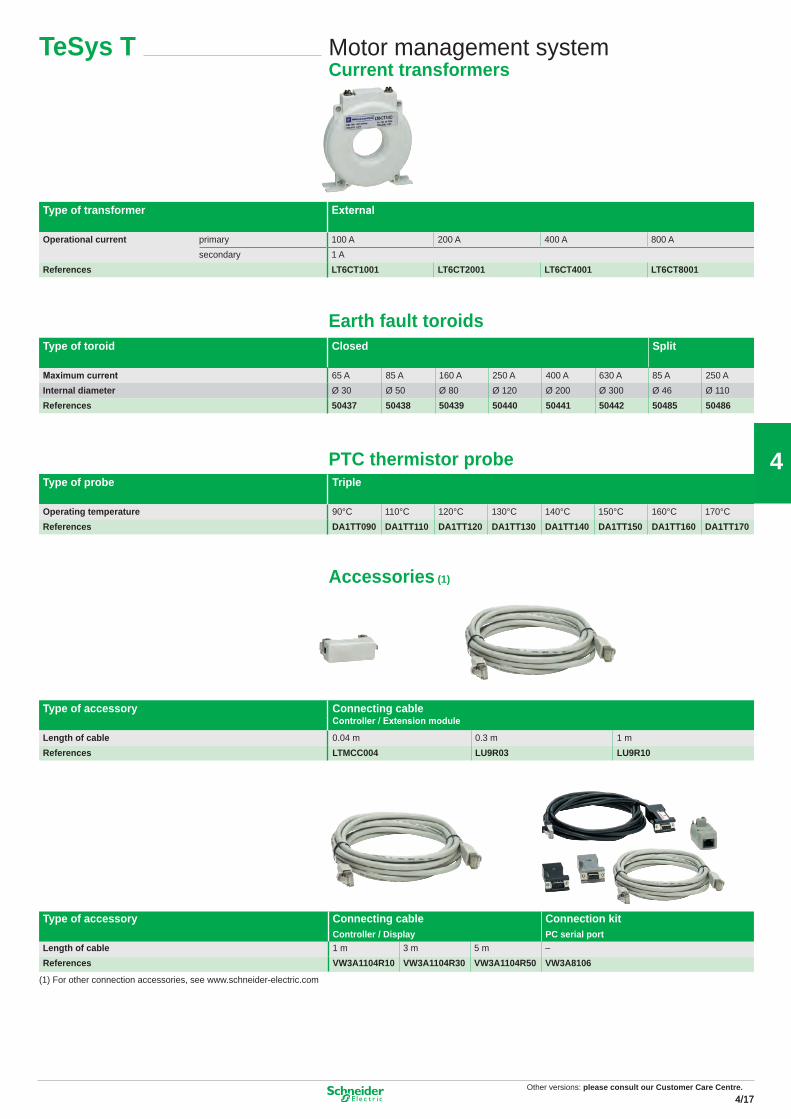
Type of transformer External
Operational current primary 100 A 200 A 400 A 800 Asecondary 1 A
Maximum current 65 A 85 A 160 A 250 A 400 A 630 A 85 A 250 AInternal diameter Ø 30 Ø 50 Ø 80 Ø 120 Ø 200 Ø 300 Ø 46 Ø 110References 50437 50438 50439 50440 50441 50442 50485 50486
Maximum current 65 A 85 A 160 A 250 A 400 A 630 A 85 A 250 AInternal diameter Ø 30 Ø 50 Ø 80 Ø 120 Ø 200 Ø 300 Ø 46 Ø 110References 50437 50438 50439 50440 50441 50442 50485 50486
Type of accessory Connecting cableController / Extension module
Length of cable 0.04 m 0.3 m 1 mReferences LTMCC004 LU9R03 LU9R10
Type of accessory Connecting cableController / Display
Connection kitPC serial port
Length of cable 1 m 3 m 5 m –References VW3A1104R10 VW3A1104R30 VW3A1104R50 VW3A8106
(1) For other connection accessories, see www.schneider-electric.com
Motor management systemCurrent transformers
TeSys T
Other versions: Please consult our Customer Care Centre.
17
Other versions: please consult our Customer Care Centre.4/18
4
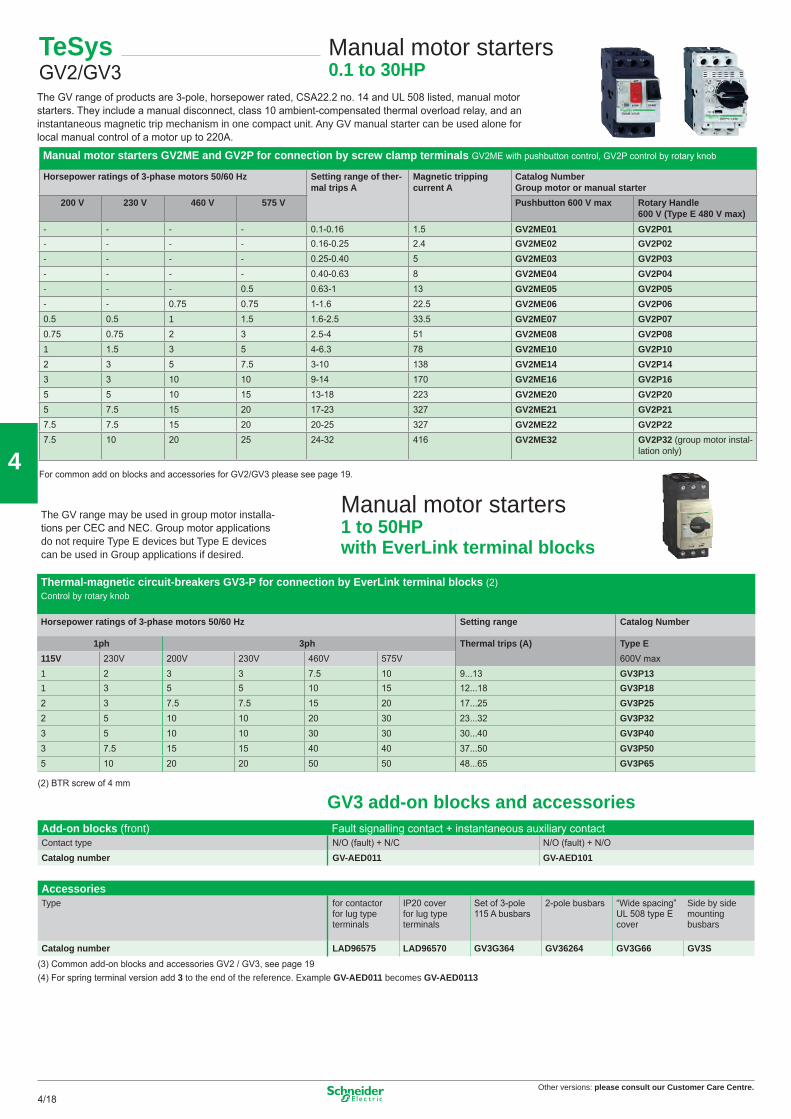
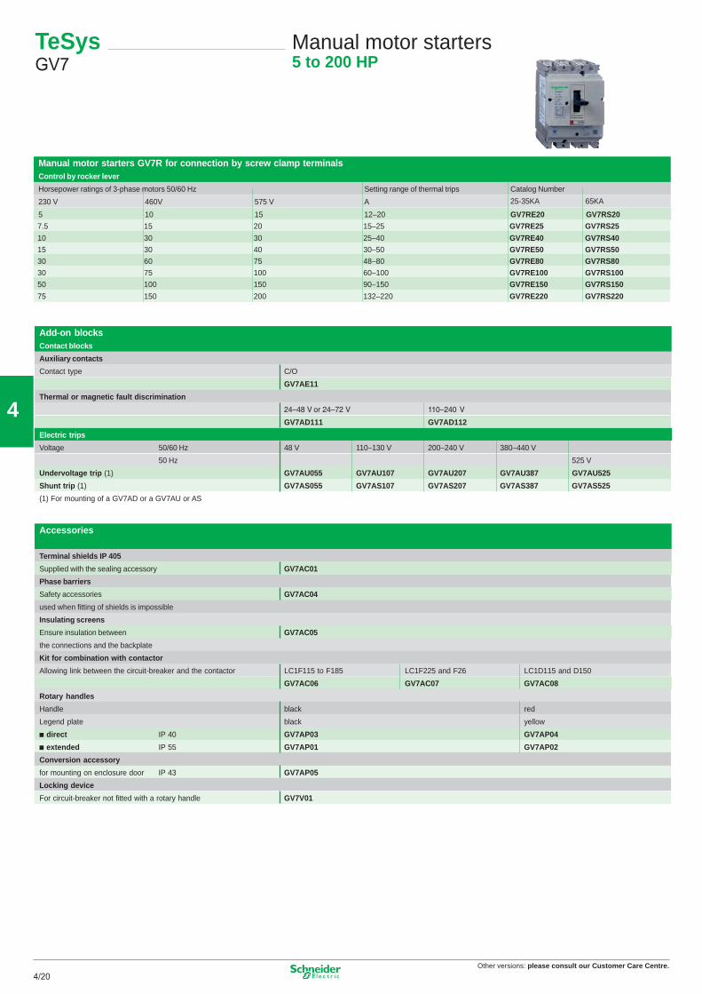
Manual motor starters 1 to 50HP with EverLink terminal blocks
(2) BTR screw of 4 mm
GV3 add-on blocks and accessoriesAdd-on blocks (front) Fault signalling contact + instantaneous auxiliary contactContact type N/O (fault) + N/C N/O (fault) + N/OCatalog number GV-AED011 GV-AED101
AccessoriesType for contactor
for lug type terminals
IP20 cover for lug type terminals
Set of 3-pole 115 A busbars
2-pole busbars “Wide spacing” UL 508 type E cover
Side by side mounting busbars
Catalog number LAD96575 LAD96570 GV3G364 GV36264 GV3G66 GV3S(3) Common add-on blocks and accessories GV2 / GV3, see page 19(4) For spring terminal version add 3 to the end of the reference. Example GV-AED011 becomes GV-AED0113
TeSysGV2/GV3
Manual motor starters0.1 to 30HP
The GV range of products are 3-pole, horsepower rated, CSA22.2 no. 14 and UL 508 listed, manual motor starters. They include a manual disconnect, class 10 ambient-compensated thermal overload relay, and an instantaneous magnetic trip mechanism in one compact unit. Any GV manual starter can be used alone for local manual control of a motor up to 220A.
The GV range may be used in group motor installa-tions per CEC and NEC. Group motor applications do not require Type E devices but Type E devices can be used in Group applications if desired.
Thermal-magnetic circuit-breakers GV3-P for connection by EverLink terminal blocks (2)Control by rotary knob
Horsepower ratings of 3-phase motors 50/60 Hz Setting range Catalog Number
For common add on blocks and accessories for GV2/GV3 please see page 19.
18
Other versions: please consult our Customer Care Centre.4/194/19
4
TeSys GV2/GV3
Circuit-breakersAccessories
Accessories GV2Combination blockFor mounting on LC1-K or LP1-K LC1-D09…D38 LAD-31 and LC1-D09…D38
GV2-AF01 GV2-AF3 GV2-AF4Sets of 3-pole busbars63 A Pitch 45 mm 54 mm 72 mmNumber of tap-offs 2 GV2-G245 GV2-G254 GV2-G272
3 GV2-G345 GV2-G354 4 GV2-G445 GV2-G454 GV2-G472 5 GV2-G554Protective end coverFor unused busbar outlets GV1-G10Terminal blocksFor supply to one or more GV2-G busbar sets connection from the top can be fi tted with current limiter GV1-L3 (GV2-ME and GV2-P)
GV1-G09 GV1-G05Padlockable external operator for GV2 and GV3 (150 to 290 mm)Padlocking In “On” and “Off” position In “Off” position Handle black redLegend plate blue yellowIP 54 For GV2-ME/P/L GV2-AP01 GV2-AP02
For GV3-P GV3-AP01 GV3-AP02
For GV2-P Type UL508E (not required by CSA) GV2-GH7For GV3-P Type UL508E (not required by CSA) GV3-G66
Add-on blocks common to GV2 / GV3Contact blocksContact types N/O or N/C N/O + N/C N/O + N/O (fault) + N/C (fault) + N/O C/O commonInstantaneous auxiliary contacts pointMounting front GV-AE1 GV-AE11 GV-AE20
LH side GV-AN11 GV-AN20Fault signalling contact + instantaneous auxiliary contact
LH side “F” fault GV-AD1001 GV-AD1010 “O” fault GV-AD0101 GV-AD0110
Short-circuit signalling contactLH side GV-AM11
Electric tripsUndervoltage or shunt trips (Replace • in catalog number with "S"
Side mounting (1 block on RH side of circuit-breaker) 50 Hz 60 HzVoltage 24 V GV-A•025 GV-A•026
110…115 V GV-A•115 GV-A•116120…127 V GV-A 125200…220 V GV-A•207220…240 V GV-A•225 GV-A•226380…400 V GV-A•385 GV-A•386
GV-A•415480 V 600 V GV-A•505
Padlocking deviceFor use with up to 4 padlocks (padlocks not supplied) Ø 6 mm shank max GV2-V03
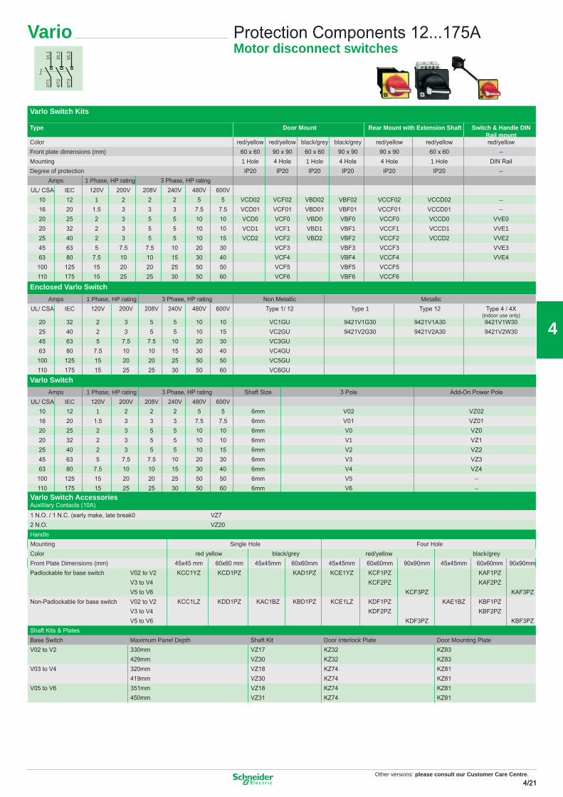
Varlo Switch AccessoriesAuxilliary Contacts (10A)1 N.O. / 1 N.C. (early make, late break0 VZ72 N.O. VZ20HandleMounting Single Hole Four HoleColor red yellow black/grey red/yellow black/greyFront Plate Dimensions (mm) 45x45 mm 60x60 mm 45x45mm 60x60mm 45x45mm 60x60mm 90x90mm 45x45mm 60x60mm 90x90mmPadlockable for base switch V02 to V2 KCC1YZ KCD1PZ KAD1PZ KCE1YZ KCF1PZ KAF1PZ
V3 to V4 KCF2PZ KAF2PZV5 to V6 KCF3PZ KAF3PZ
Non-Padlockable for base switch V02 to V2 KCC1LZ KDD1PZ KAC1BZ KBD1PZ KCE1LZ KDF1PZ KAE1BZ KBF1PZV3 to V4 KDF2PZ KBF2PZV5 to V6 KDF3PZ KBF3PZ
Shaft Kits & PlatesBase Switch Maximum Panel Depth Shaft Kit Door Interlock Plate Door Mounting PlateV02 to V2 330mm VZ17 KZ32 KZ83
429mm VZ30 KZ32 KZ83V03 to V4 320mm VZ18 KZ74 KZ81
419mm VZ30 KZ74 KZ81V05 to V6 351mm VZ18 KZ74 KZ81
450mm VZ31 KZ74 KZ81
1/L1
2/T1
3/L2
4/T2
5/L3
6/T3
Other versions: Please consult our Customer Care Centre.
21
Other versions: please consult our Customer Care Centre.4/22
4
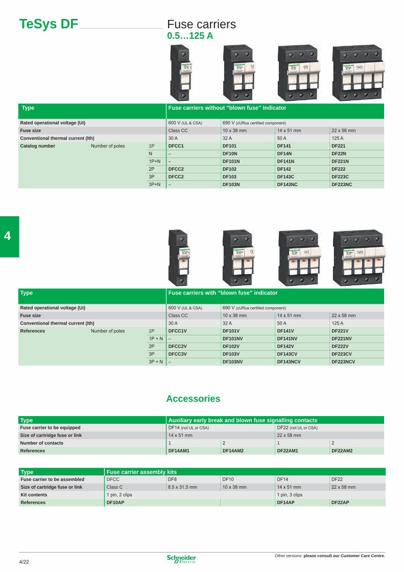
TeSys DF Fuse carriers0.5…125 A
Type Fuse carriers without “blown fuse” indicator
Rated operational voltage (Ui) 600 V (UL & CSA) 690 V (cURus certifi ed component)
Fuse size Class CC 10 x 38 mm 14 x 51 mm 22 x 58 mmConventional thermal current (Ith) 30 A 32 A 50 A 125 ACatalog number Number of poles 1P DFCC1 DF101 DF141 DF221
Rated operational voltage (Ui) 600 V (UL & CSA) 690 V (cURus certifi ed component)
Fuse size Class CC 10 x 38 mm 14 x 51 mm 22 x 58 mmConventional thermal current (Ith) 30 A 32 A 50 A 125 AReferences Number of poles 1P DFCC1V DF101V DF141V DF221V
Type Auxiliary early break and blown fuse signalling contactsFuse carrier to be equipped DF14 (not UL or CSA) DF22 (not UL or CSA)
Size of cartridge fuse or link 14 x 51 mm 22 x 58 mmNumber of contacts 1 2 1 2References DF14AM1 DF14AM2 DF22AM1 DF22AM2
Type Fuse carrier assembly kitsFuse carrier to be assembled DFCC DF8 DF10 DF14 DF22Size of cartridge fuse or link Class C 8.5 x 31.5 mm 10 x 38 mm 14 x 51 mm 22 x 58 mmKit contents 1 pin, 2 clips 1 pin, 3 clipsReferences DF10AP DF14AP DF22AP
22
Other versions: please consult our Customer Care Centre.4/234/23
4
TeSys LS1
Fuse carriers0…32 A
Basic blocksconnection
Fuse Carriers
Rated operational voltage with links, a.c. supply 600 V 690 V 690 VMaximum continuous current for ambient temperature ≤ 40° C
with links (mm2/A)with CC or KTK-R (wire gauge/A) 2 - #8 AWG/30A max
with aM fuses (mm2/A)
4/25A or 2.5/16A4/22A or 2.5/20A
6/32A or 4/25A or 2.5/16A
6/32A or 4/22A or 2.5/20A
6/32A or 2.5/20A or 1.5/16Awith gG fuses (mm2/A) 2.5/20A or 1.5/16A
Conforming to standards CSA/ULNF EN 60947-3IEC 947-3
Product certifi
cationsFuse carrier type
Rating 30A 25A 32ACartridge fuse size Type CC or KTK-R 10 x 38 10 x 38Screw clamp connection 3-pole LS1D30 LS1-D32 4-pole LS1-D32+LA8-D324Spring terminal connection 3-pole LS1D303 LS1D323
LS1D30 LS1D323BV UR BV UR
LS1D32
Add-on blocksContact blocksFor use on LS1D30 LS1D32 LS1D323Contact type N/O+N/C N/O+N/O N/O+N/C N/O+N/O N/O+N/C N/O+N/OInstantaneous auxiliary contacts Front mounting GVAE11 GVAE20 GVAE11 GVAE20 GVAE113 GVAE203
Other versions: Please consult our Customer Care Centre.
23
Other versions: please consult our Customer Care Centre.4/24
4
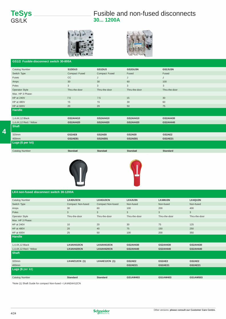
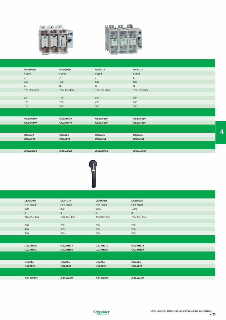
GS1/2 Fusible disconnect switch 30-800A
Catalog Number S1DDU3 GS1DU3 GS2GU3N GS2JU3N GS2MU3N GS2QU3N GS2SU3 GS2TU3Switch Type Compact Fused Compact Fused Fused Fuse used Fused Fused Fused
Catalog Number Standard Standard GS1AW403 GS1AW403 GS1AW503 GS1AW503 GS1AW903 GS1AW903 GS1AW903
*Note (1) Shaft Guide for compact Non-fused = LK4AEAH12CN
Compact 30A SwitchLK4DU3
200A SwitchLK4MU3
200A SwitchGS2MU3
800A SwitchGS2TU3
Other versions: Please consult our Customer Care Centre.
25
Other versions: please consult our Customer Care Centre.4/26
4
Standard control circuit voltages24 V DC BL24 V AC B48 V AC / 48...72 V DC ES110...240 V AC / 110...220 V DC FU
(2) Complete the references of the power bases according to the following table. Example: LU2B12 **(3) Complete the references of the control units according to the following table. Example: LUCA/B/D/M6X **
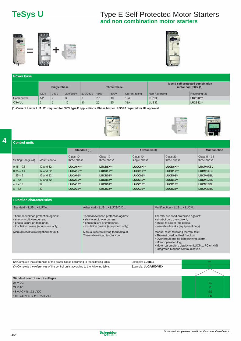
Manual reset following thermal fault. • Thermal overload test function. • Overtorque and no-load running, alarm, • Motor operation log, • Motor parameters display on LUCM.., PC or HMI • Integrated Modbus communication.
TeSys U Type E Self Protected Motor Startersand non combination motor starters
(1) Current limiter LUALB1 required for 600V type E applications, Phase barrier LU9SP0 required for UL approval
= +
26
Other versions: please consult our Customer Care Centre.4/274/27
4
TeSys U Starter-controller for 3-phase motorsFunction modules
Type of optional function Thermal Thermal fault signalling Motor loadoverload alarm indication
Compatible with LUCA NO NO NO NO NOCompatible with LUCL NO NO NO NO NOCompatible with LUCB, LUCD YES YES YES YES YESCompatible with LUCM NO NO NO NO YESOutput signal 1 NO 1 NO +1 NC 1 NC 1 NO 4…20 mAReset NA Manual Automatic or remote NAReferences LUFW10 LUFDH11 LUFDA01 LUFDA10 LUFV2
Type of communication Modbus Advantys Profi bus DP CANopen DeviceNet AS-Interface ParallelSTB wiring
Only compatible with 24 V DC control units YES YES YES YES YES YES YESLUCA..BL, LUCB..BL, LUCD..BL, LUCM..BLTransfer speed 19.2 Kbps Dpg. on NIM (1) 9,6…12 Mbps 20 K…1 Mbps 125…500 Kbaud 167 Kbps NANumber of slaves 31 per Modbus Dpg. on Network 125 per Profi bus DP 128 per CANopen 63 per DeviceNet 62 per AS-Interface 8 per LU9GC02
Information carried by the Modbus, Advantys STB or CANopen busType of control unit LUCAppBL LUCBppBL, LUCDppBL LUCMppBLStart and Stop commands X X XStarter status (ready, running, fault) X X XThermal alarm X XRemote reset via the bus X XIndication of motor load X XSignalling and fault differentiation X XAlarms (overcurrent, …) XRemote programming and monitoring of all the functions X“Log” function XMonitoring function X
Type of contact block Add-on Auxiliary
Signalling contacts of any fault NC (95-96) NO (97-98) – – –position of control handle NO (17-18) NO (17-18) – – –
2 auxiliary contacts module – – NO (33-34) NC (31-32) NC (31-32)– – NO (43-44) NO (43-44) NC (41-42)
phase failure or imbalance, insulation breaks (equipmemt only).
- Manual, automatic or remote reset,- Thermal overload test function,- Overtorque and no-load running, alarm,- Motor operation log,- Motor parameters display on LUCM.., PC or HMI,- Integrated Modbus communication.
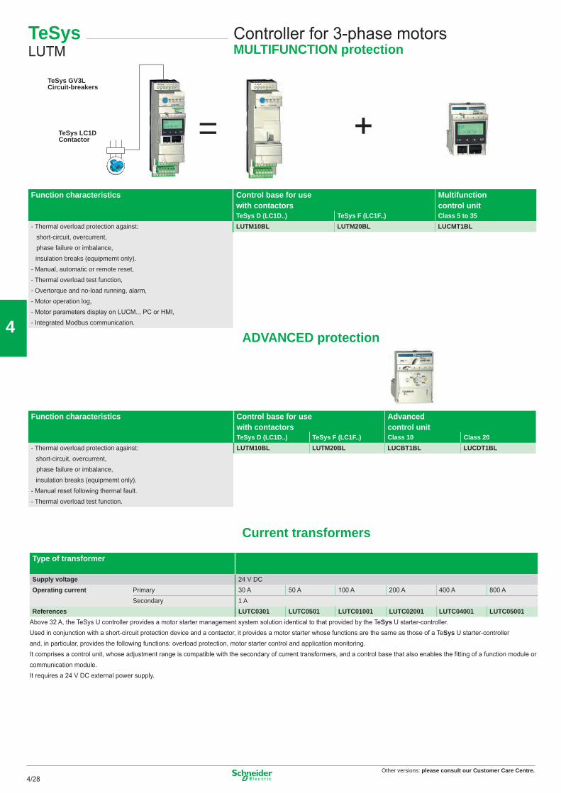
Function characteristics Control base for use Advancedwith contactors control unitTeSys D (LC1D..) TeSys F (LC1F..) Class 10 Class 20
Above 32 A, the TeSys U controller provides a motor starter management system solution identical to that provided by the TeSys U starter-controller.Used in conjunction with a short-circuit protection device and a contactor, it provides a motor starter whose functions are the same as those of a TeSys U starter-controllerand, in particular, provides the following functions: overload protection, motor starter control and application monitoring.It comprises a control unit, whose adjustment range is compatible with the secondary of current transformers, and a control base that also enables the fi tting of a function module orcommunication module.It requires a 24 V DC external power supply.
= +TeSys GV3L
TeSys LC1DContactor
Circuit-breakers
ADVANCED protection
Current transformers
28
Other versions: please consult our Customer Care Centre.4/294/29
4
TeSys LUTM
Controller for 3-phase motorsFunction modules
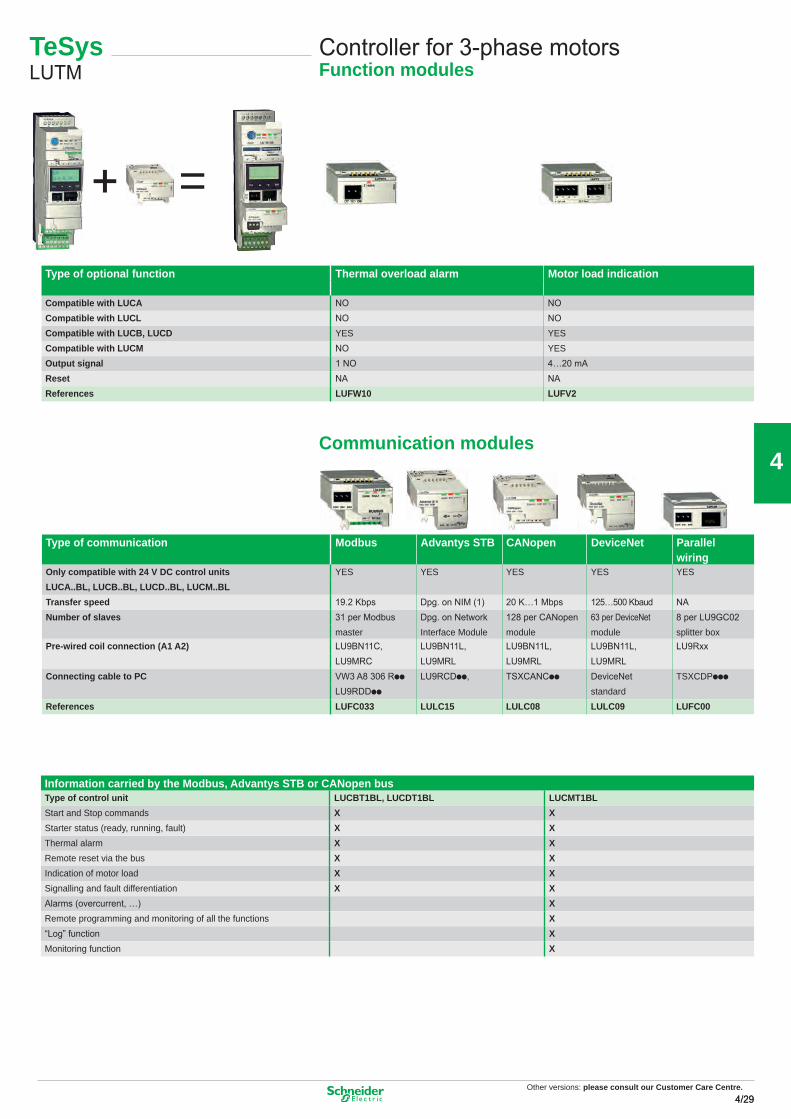
Type of optional function Thermal overload alarm Motor load indication
Compatible with LUCA NO NOCompatible with LUCL NO NOCompatible with LUCB, LUCD YES YESCompatible with LUCM NO YESOutput signal 1 NO 4…20 mAReset NA NAReferences LUFW10 LUFV2
Type of communication Modbus Advantys STB CANopen DeviceNet Parallelwiring
Only compatible with 24 V DC control units YES YES YES YES YESLUCA..BL, LUCB..BL, LUCD..BL, LUCM..BLTransfer speed 19.2 Kbps Dpg. on NIM (1) 20 K…1 Mbps 125…500 Kbaud NANumber of slaves 31 per Modbus Dpg. on Network 128 per CANopen 63 per DeviceNet 8 per LU9GC02
Information carried by the Modbus, Advantys STB or CANopen busType of control unit LUCBT1BL, LUCDT1BL LUCMT1BLStart and Stop commands X XStarter status (ready, running, fault) X XThermal alarm X XRemote reset via the bus X XIndication of motor load X XSignalling and fault differentiation X XAlarms (overcurrent, …) XRemote programming and monitoring of all the functions X“Log” function XMonitoring function X
=+
Communication modules
Other versions: Please consult our Customer Care Centre.
29
Other versions: please consult our Customer Care Centre.4/30
4
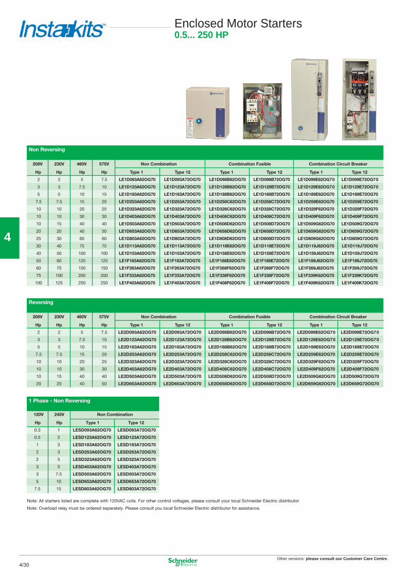
Enclosed Motor Starters0.5... 250 HP
One Operator
Two Operators
Three Operators
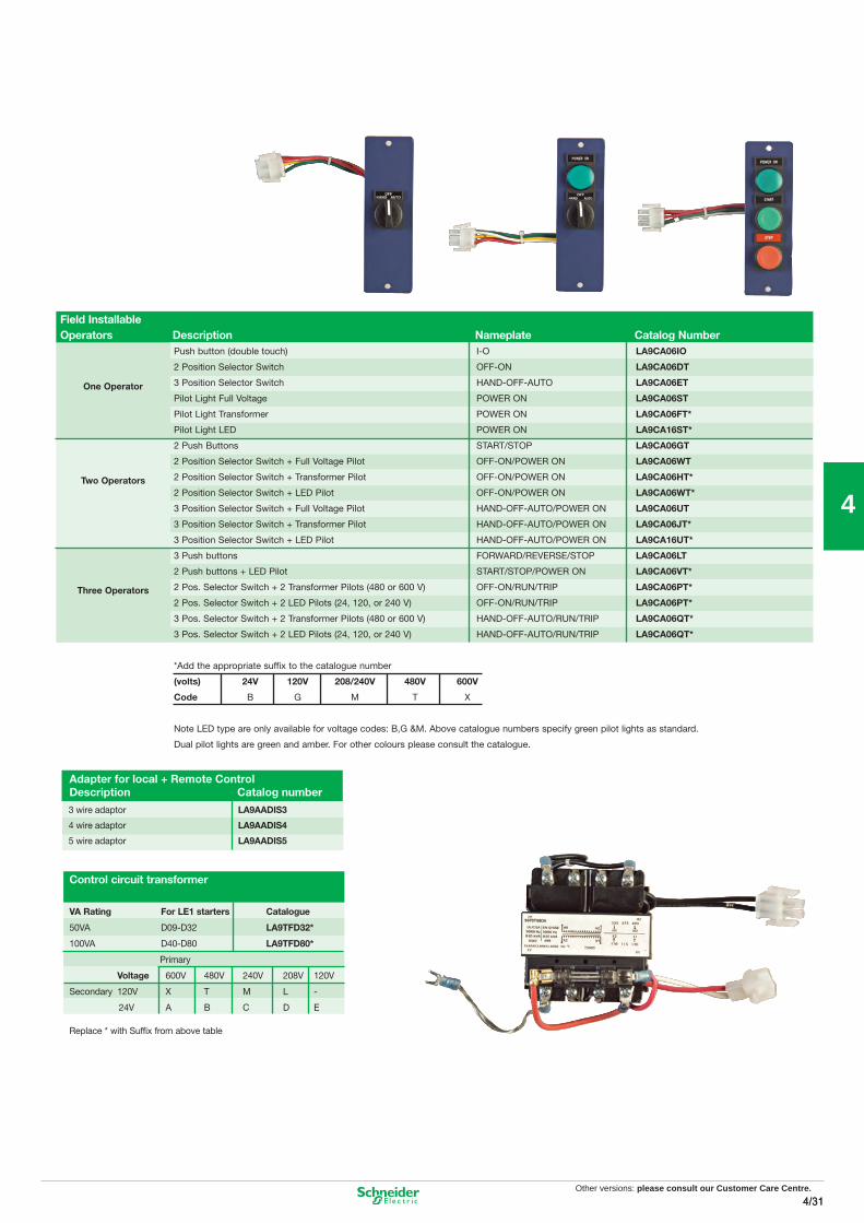
Field InstallableOperators Description Nameplate Catalog Number
Push button (double touch) I-O LA9CA06IO
2 Position Selector Switch OFF-ON LA9CA06DT
3 Position Selector Switch HAND-OFF-AUTO LA9CA06ET
Pilot Light Full Voltage POWER ON LA9CA06ST
Pilot Light Transformer POWER ON LA9CA06FT*
Pilot Light LED POWER ON LA9CA16ST*
2 Push Buttons START/STOP LA9CA06GT
2 Position Selector Switch + Full Voltage Pilot OFF-ON/POWER ON LA9CA06WT
2 Position Selector Switch + Transformer Pilot OFF-ON/POWER ON LA9CA06HT*
2 Position Selector Switch + LED Pilot OFF-ON/POWER ON LA9CA06WT*
3 Position Selector Switch + Full Voltage Pilot HAND-OFF-AUTO/POWER ON LA9CA06UT
3 Position Selector Switch + Transformer Pilot HAND-OFF-AUTO/POWER ON LA9CA06JT*
3 Position Selector Switch + LED Pilot HAND-OFF-AUTO/POWER ON LA9CA16UT*
3 Push buttons FORWARD/REVERSE/STOP LA9CA06LT
2 Push buttons + LED Pilot START/STOP/POWER ON LA9CA06VT*
2 Pos. Selector Switch + 2 Transformer Pilots (480 or 600 V) OFF-ON/RUN/TRIP LA9CA06PT*
2 Pos. Selector Switch + 2 LED Pilots (24, 120, or 240 V) OFF-ON/RUN/TRIP LA9CA06PT*
3 Pos. Selector Switch + 2 Transformer Pilots (480 or 600 V) HAND-OFF-AUTO/RUN/TRIP LA9CA06QT*
3 Pos. Selector Switch + 2 LED Pilots (24, 120, or 240 V) HAND-OFF-AUTO/RUN/TRIP LA9CA06QT*
*Add the appropriate suffix to the catalogue number
(volts) 24V 120V 208/240V 480V 600V
Code B G M T X
Note LED type are only available for voltage codes: B,G &M. Above catalogue numbers specify green pilot lights as standard.
Dual pilot lights are green and amber. For other colours please consult the catalogue.
C
Adapter for local + Remote ControlDescription Catalog number
Note: All starters listed are complete with 120VAC coils. For other control voltages, please consult your local Schneider Electric distributor.
Note: Overload relay must be ordered separately. Please consult you local Schneider Electric distributor for assistance.
LESD093A62OG70
LESD123A62OG70
LESD183A62OG70
LESD253A62OG70
LESD323A62OG70
LESD403A62OG70
LESD503A62OG70
LESD653A62OG70
LESD803A62OG70
Other versions: Please consult our Customer Care Centre.
31
Other versions: please consult our Customer Care Centre.4/32
4
TeSysQuickfi t
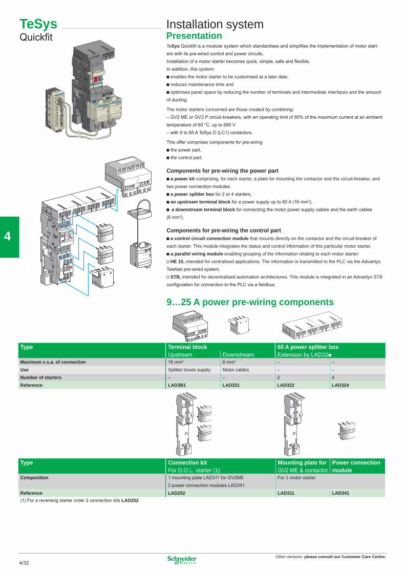
Installation systemPresentationTeSys Quickfi t is a modular system which standardises and simplifi es the implementation of motor start-ers with its pre-wired control and power circuits.Installation of a motor starter becomes quick, simple, safe and fl exible.In addition, this system:b enables the motor starter to be customised at a later date,b reduces maintenance time andb optimises panel space by reducing the number of terminals and intermediate interfaces and the amount of ducting.
The motor starters concerned are those created by combining:– GV2 ME or GV3 P circuit-breakers, with an operating limit of 80% of the maximum current at an ambient temperature of 60 °C, up to 690 V– with 9 to 65 A TeSys D (LC1) contactors.
This offer comprises components for pre-wiringb the power part,b the control part.
Components for pre-wiring the power partb a power kit comprising, for each starter, a plate for mounting the contactor and the circuit-breaker, and two power connection modules,b a power splitter box for 2 or 4 starters,b an upstream terminal block for a power supply up to 60 A (16 mm2),b a downstream terminal block for connecting the motor power supply cables and the earth cables (6 mm2).
Components for pre-wiring the control partb a control circuit connection module that mounts directly on the contactor and the circuit-breaker of each starter. This module integrates the status and control information of this particular motor starter.b a parallel wiring module enabling grouping of the information relating to each motor starter:v HE 10, intended for centralised applications. The information is transmitted to the PLC via the Advantys Telefast pre-wired system.v STB, intended for decentralised automation architectures. This module is integrated in an Advantys STB confi guration for connection to the PLC via a fi eldbus.
9…25 A power pre-wiring components
Type Terminal block 60 A power splitter boxUpstream Downstream Extension by LAD32p
Maximum c.s.a. of connection 16 mm2 6 mm2 – –Use Splitter boxes supply Motor cables – –Number of starters – – 2 4Reference LAD3B1 LAD331 LAD322 LAD324
Type Connection kit Mounting plate for Power connectionFor D.O.L. starter (1) GV2 ME & contactor module
Composition 1 mounting plate LAD311 for GV2ME For 1 motor starter2 power connection modules LAD341
Reference LAD252 LAD311 LAD341(1) For a reversing starter order 2 connection kits LAD252
32
Other versions: please consult our Customer Care Centre.4/334/33
4
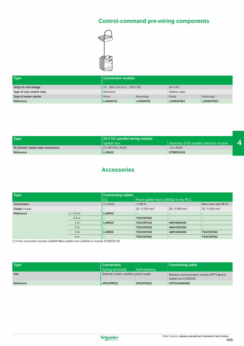
Type Connection module
TeSys D coil voltage 12…250 V AC or 5…130 V DC 24 V DCType of coil control relay Electronic Without relayType of motor starter Direct Reversing Direct ReversingReference LAD9AP31 LAD9AP32 LAD9AP3D1 LAD9AP3D2
Type 24 V DC parallel wiring moduleSplitter box Advantys STB parallel interface module
PLC/motor starter side connectors 2 x HE10/8 x RJ45 –/4 x RJ45Reference LU9G02 STBEPI2145
Accessories
Type Connecting cables(1) From splitter box LU9G02 to the PLC
Connectors 2 x RJ45 2 HE10 Bare wires and HE10Gauge / c.s.a. – 22 / 0.324 mm2 28 / 0.080 mm2 22 / 0.324 mm2
Reference L = 0.3 m LU9R03 – – – 0.5 m – TSXCDP053 – – 1 m LU9R10 TSXCDP103 ABFH20H100 – 2 m – TSXCDP203 ABFH20H200 – 3 m LU9R30 TSXCDP303 ABFH20H300 TSXCDP301 5 m – TSXCDP503 – TSXCDP301
(1) From connection module LAD9AP3p to splitter box LU9G02 or module STBEPI2145
Type Connectors Connecting cableSpring terminals Self-stripping
Use External contact, auxiliary power supply Between communication module APP1Cp andsplitter box LU9GG02
Reference APE1PRE21 APE1PAD21 APP2AH40H060
Control-command pre-wiring components
Other versions: Please consult our Customer Care Centre.
33
Other versions: please consult our Customer Care Centre.4/34
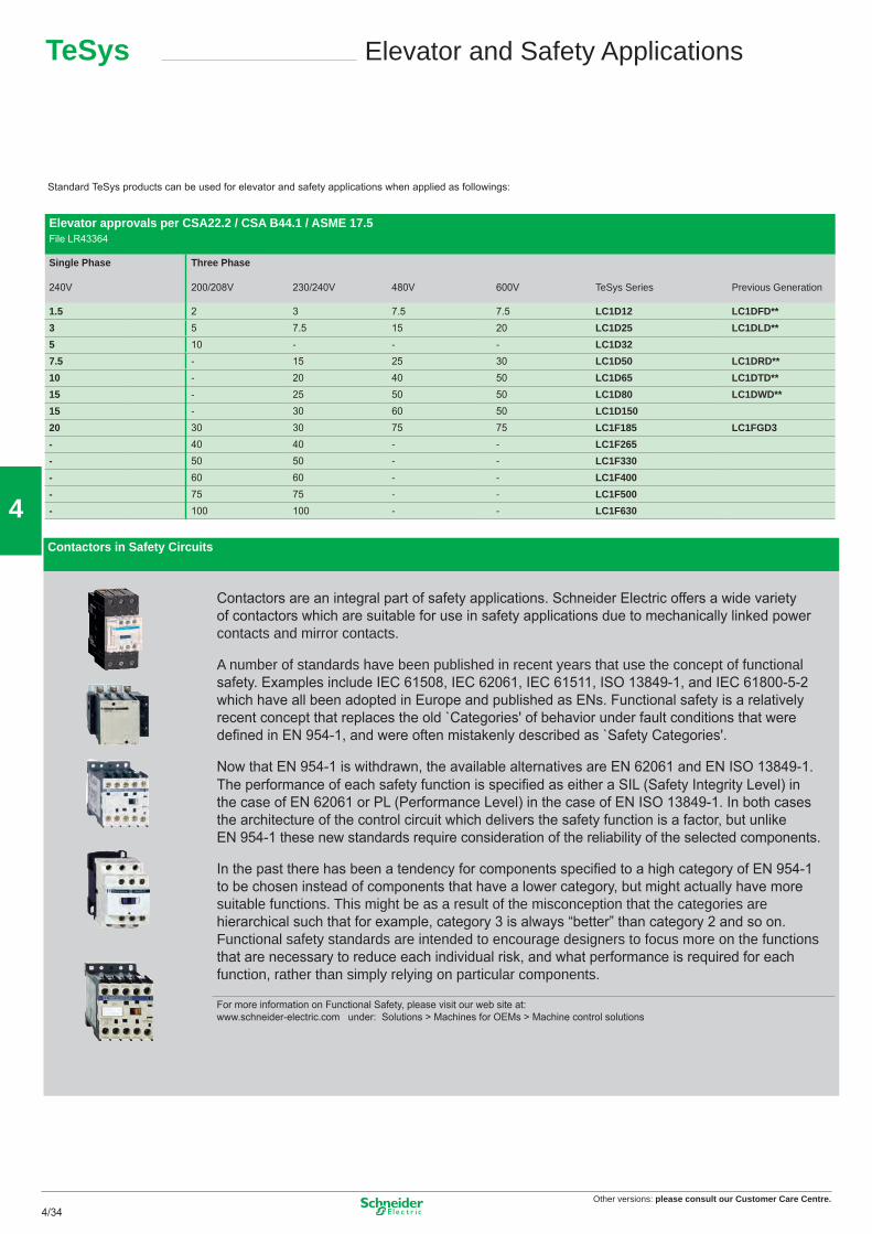
4Contactors in Safety Circuits
Contactors are an integral part of safety applications. Schneider Electric offers a wide variety of contactors which are suitable for use in safety applications due to mechanically linked power contacts and mirror contacts.
A number of standards have been published in recent years that use the concept of functional safety. Examples include IEC 61508, IEC 62061, IEC 61511, ISO 13849-1, and IEC 61800-5-2 which have all been adopted in Europe and published as ENs. Functional safety is a relatively recent concept that replaces the old `Categories' of behavior under fault conditions that were defi ned in EN 954-1, and were often mistakenly described as `Safety Categories'.
Now that EN 954-1 is withdrawn, the available alternatives are EN 62061 and EN ISO 13849-1.The performance of each safety function is specifi ed as either a SIL (Safety Integrity Level) in the case of EN 62061 or PL (Performance Level) in the case of EN ISO 13849-1. In both cases the architecture of the control circuit which delivers the safety function is a factor, but unlike EN 954-1 these new standards require consideration of the reliability of the selected components.
In the past there has been a tendency for components specifi ed to a high category of EN 954-1 to be chosen instead of components that have a lower category, but might actually have more suitable functions. This might be as a result of the misconception that the categories are hierarchical such that for example, category 3 is always “better” than category 2 and so on. Functional safety standards are intended to encourage designers to focus more on the functions that are necessary to reduce each individual risk, and what performance is required for each function, rather than simply relying on particular components.
For more information on Functional Safety, please visit our web site at: www.schneider-electric.com under: Solutions > Machines for OEMs > Machine control solutions
Elevator approvals per CSA22.2 / CSA B44.1 / ASME 17.5File LR43364
Single Phase
240V
Three Phase
200/208V 230/240V 480V 600V TeSys Series Previous Generation
Standard TeSys products can be used for elevator and safety applications when applied as followings:
34
Combination Starters – Type E & Type F
UL508A & Control Panels
Group Protection
TeSys Applications InformationGroup Motor and Type E
Combination Starters are the most common type of packaged motor starter. They are called ‘Combination’ because of their structure and their combined functions. The fi gure opposite shows the four combined functions that constitute a complete motor starter circuit, defi ned as a “Motor branch circuit” by the CEC and NEC. CSA 22.2 no 14 and UL508 currently give different types of combination starter that meet the requirements of a «Motor branch circuit».
Type E, called “self-protected combination starter”, covers all these functions and can be controlled manually (thermal-magnetic circuit-breaker) or remotely (starter-controller). Type E starters withstand faults within their declared nominal rating without sustaining damage, after which they can be put back into service. In addition, they can withstand more severe short-circuit and durability performance tests without welding or excessive wear of the contact tips.
Type F, called “Combination motor starter”, consists of a type E manual starter (thermal-magnetic circuit-breaker) combined with a contactor. These starters are evaluated by means of basic short-circuit tests, but are not considered as “self-protected”. For this combination, the type E starter must be marked “Combination Motor Controller when used with ...”, followed by the reference of the load side contactor.
At present, CSA does not recognize Type F combinations. Manual starters used with contactors can be used in Group Protection as described below.
To help users properly coordinate their motor control equipment with their distribution system in the event of a fault, article 409 of the 2005 NEC requires panel builders to list the short-circuit withstand rating of their motor control panels. According to standard UL508A, manufacturers must use the short-circuit withstand value of the lowest rated device as the nominal withstand rating of the panel, unless the devices have been tested together for a higher coordinated rating. The minimum “short-circuit current rating” (SCCR), on motor control components for horsepower ratings of 50 hp or below is 5000 A. Using a type E or type F combination starter eliminates the coordination problems of using individual components for the “motor branch circuit protection”, “motor controller” and “motor overload protection” functions. The panel builder uses the declared short-circuit current rating for the combination starter. This value is generally higher than 5000 A. This makes it easier to list the short-circuit current ratings and to check the compatibility of a UL508A motor control panel within a given distribution system.
1 Motor disconnect (disconnect switch) 2 Motor Branch Circuit Protection (short circuit protection) 3 Motor controller (contactor) 4 Motor Overload Protection (thermal overload relay)
Both the CEC and NEC allow a single short-circuit protection device to be used for more than one motor circuit if the components used are marked and listed for such use. Components suitable for use in group protection, known as “motor group installations”, can be marked in one of the following two ways: Case n° 1 The contactor and the motor overload relay are both listed as suitable for group installation. An inverse time circuit-breaker can be used as the short-circuit protection device if it is also listed as suitable for group installation. The panel builder must therefore make sure that the short-circuit protection device selected (fuses or inverse time circuit-breaker) does not exceed the value allowed by rule 28-206 of the CEC or article 430.40 of the NEC for the smallest overload relay used in the circuit. Once these conditions have been met, the panel buil-der can reduce the size of the conductor connecting the short-circuit protection device to the individual motor contactor/overload relay, to one third of the size of the upstream circuit conductor supplying the protection device. The panel builder must limit the length of the motor starter conductor (connecting the short-circuit protection device to the motor contactor/overload relay) to a maximum of 7.5 m (25 feet). Case n° 2 (Not approved under the CEC for US export applications only) The motor contactor and overload relay are listed as suitable for “tap conductor protection” in group installations. This category allows the panel designer to reduce the size of the conductor connecting the short-circuit protection device to the individual motor contactor/overload relay, to one tenth of the size of the upstream circuit conductor supplying the protection device. The designer must limit the length of this conductor to a maximum of 3.05 m (10 feet). In both cases, the supply circuits must not be less than 125 % of the connec-ted motor FLA (Full Load Amps) rating. For panel builders, using type F combination starters in group installations simplifi es group motor considerations. Each starter is a fully coordinated motor branch circuit. The panel builder follows the same NEC requirements for sizing the supply conductors as those required for single motor branch circuits. The size of the supply conductors can be reduced in accor-dance with the specifi cations of article 430.28. This allows the same fl exibility in conductor sizing as that offered in article 430.53 (D), without a requirement to check the short-circuit protection rating marked on the components and the overload relay limit. A UL508A panel does not need a short-circuit protection device when each motor starter installed is a type F. The upstream short-circuit protection device supplying the starter protects the panel. The panel builder only has to consider the panel/enclosure disconnect requirements specifi ed by the NEC or local codes.
M
1
2
3
4
Other versions: Please consult our Customer Care Centre.
35
Other versions: please consult our Customer Care Centre.4/354/35
4
Combination Starters – Type E & Type F
UL508A & Control Panels
Group Protection
TeSys Applications InformationGroup Motor and Type E
Combination Starters are the most common type of packaged motor starter. They are called ‘Combination’ because of their structure and their combined functions. The fi gure opposite shows the four combined functions that constitute a complete motor starter circuit, defi ned as a “Motor branch circuit” by the CEC and NEC. CSA 22.2 no 14 and UL508 currently give different types of combination starter that meet the requirements of a «Motor branch circuit».
Type E, called “self-protected combination starter”, covers all these functions and can be controlled manually (thermal-magnetic circuit-breaker) or remotely (starter-controller). Type E starters withstand faults within their declared nominal rating without sustaining damage, after which they can be put back into service. In addition, they can withstand more severe short-circuit and durability performance tests without welding or excessive wear of the contact tips.
Type F, called “Combination motor starter”, consists of a type E manual starter (thermal-magnetic circuit-breaker) combined with a contactor. These starters are evaluated by means of basic short-circuit tests, but are not considered as “self-protected”. For this combination, the type E starter must be marked “Combination Motor Controller when used with ...”, followed by the reference of the load side contactor.
At present, CSA does not recognize Type F combinations. Manual starters used with contactors can be used in Group Protection as described below.
To help users properly coordinate their motor control equipment with their distribution system in the event of a fault, article 409 of the 2005 NEC requires panel builders to list the short-circuit withstand rating of their motor control panels. According to standard UL508A, manufacturers must use the short-circuit withstand value of the lowest rated device as the nominal withstand rating of the panel, unless the devices have been tested together for a higher coordinated rating. The minimum “short-circuit current rating” (SCCR), on motor control components for horsepower ratings of 50 hp or below is 5000 A. Using a type E or type F combination starter eliminates the coordination problems of using individual components for the “motor branch circuit protection”, “motor controller” and “motor overload protection” functions. The panel builder uses the declared short-circuit current rating for the combination starter. This value is generally higher than 5000 A. This makes it easier to list the short-circuit current ratings and to check the compatibility of a UL508A motor control panel within a given distribution system.
1 Motor disconnect (disconnect switch) 2 Motor Branch Circuit Protection (short circuit protection) 3 Motor controller (contactor) 4 Motor Overload Protection (thermal overload relay)
Both the CEC and NEC allow a single short-circuit protection device to be used for more than one motor circuit if the components used are marked and listed for such use. Components suitable for use in group protection, known as “motor group installations”, can be marked in one of the following two ways: Case n° 1 The contactor and the motor overload relay are both listed as suitable for group installation. An inverse time circuit-breaker can be used as the short-circuit protection device if it is also listed as suitable for group installation. The panel builder must therefore make sure that the short-circuit protection device selected (fuses or inverse time circuit-breaker) does not exceed the value allowed by rule 28-206 of the CEC or article 430.40 of the NEC for the smallest overload relay used in the circuit. Once these conditions have been met, the panel buil-der can reduce the size of the conductor connecting the short-circuit protection device to the individual motor contactor/overload relay, to one third of the size of the upstream circuit conductor supplying the protection device. The panel builder must limit the length of the motor starter conductor (connecting the short-circuit protection device to the motor contactor/overload relay) to a maximum of 7.5 m (25 feet). Case n° 2 (Not approved under the CEC for US export applications only) The motor contactor and overload relay are listed as suitable for “tap conductor protection” in group installations. This category allows the panel designer to reduce the size of the conductor connecting the short-circuit protection device to the individual motor contactor/overload relay, to one tenth of the size of the upstream circuit conductor supplying the protection device. The designer must limit the length of this conductor to a maximum of 3.05 m (10 feet). In both cases, the supply circuits must not be less than 125 % of the connec-ted motor FLA (Full Load Amps) rating. For panel builders, using type F combination starters in group installations simplifi es group motor considerations. Each starter is a fully coordinated motor branch circuit. The panel builder follows the same NEC requirements for sizing the supply conductors as those required for single motor branch circuits. The size of the supply conductors can be reduced in accor-dance with the specifi cations of article 430.28. This allows the same fl exibility in conductor sizing as that offered in article 430.53 (D), without a requirement to check the short-circuit protection rating marked on the components and the overload relay limit. A UL508A panel does not need a short-circuit protection device when each motor starter installed is a type F. The upstream short-circuit protection device supplying the starter protects the panel. The panel builder only has to consider the panel/enclosure disconnect requirements specifi ed by the NEC or local codes.
M
1
2
3
4
Other versions: Please consult our Customer Care Centre.
35
Other versions: please consult our Customer Care Centre.4/36
4
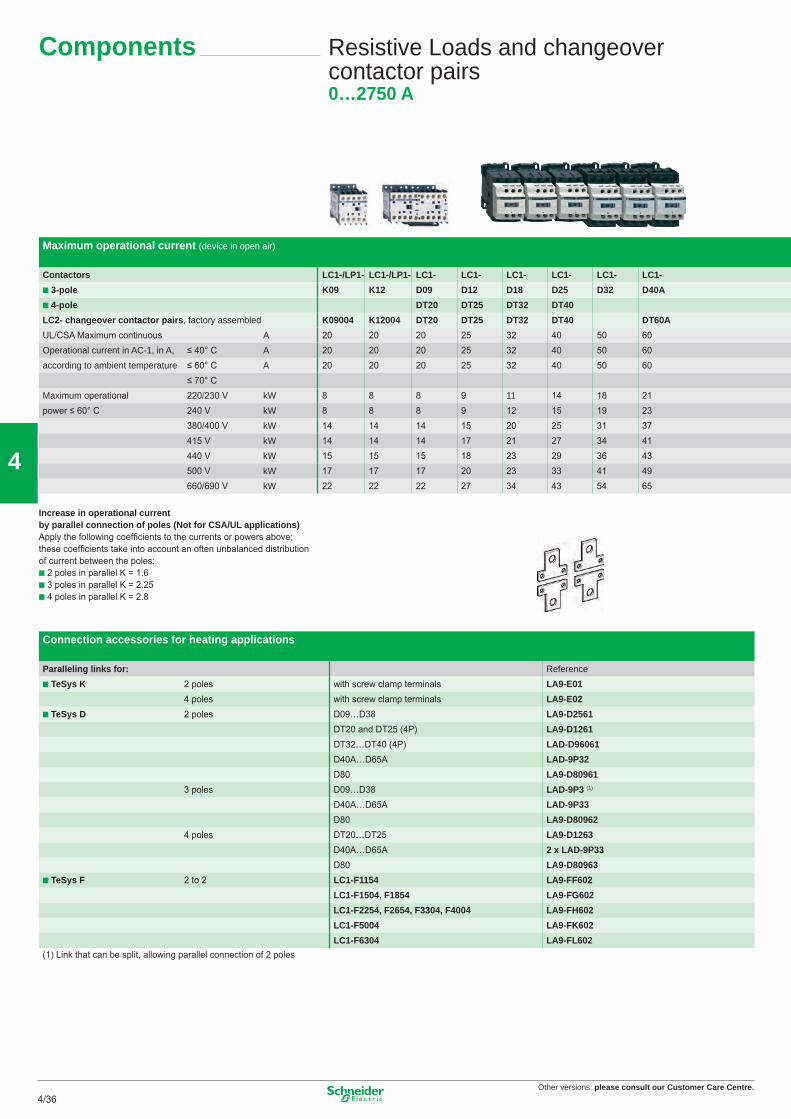
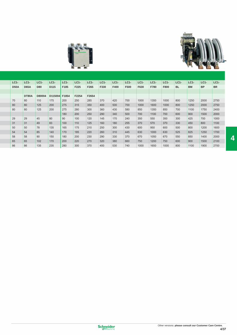
Maximum operational current (device in open air)
Contactors LC1-/LP1- LC1-/LP1- LC1- LC1- LC1- LC1- LC1- LC1-� 3-pole K09 K12 D09 D12 D18 D25 D32 D40A� 4-pole DT20 DT25 DT32 DT40LC2- changeover contactor pairs, factory assembled K09004 K12004 DT20 DT25 DT32 DT40 DT60AUL/CSA Maximum continuous A 20 20 20 25 32 40 50 60Operational current in AC-1, in A, ≤ 40° C A 20 20 20 25 32 40 50 60according to ambient temperature ≤ 60° C A 20 20 20 25 32 40 50 60
≤ 70° CMaximum operational 220/230 V kW 8 8 8 9 11 14 18 21power ≤ 60° C 240 V kW 8 8 8 9 12 15 19 23
Increase in operational current by parallel connection of poles (Not for CSA/UL applications)Apply the following coeffi cients to the currents or powers above; these coeffi cients take into account an often unbalanced distribution of current between the poles:� 2 poles in parallel K = 1.6� 3 poles in parallel K = 2.25� 4 poles in parallel K = 2.8
Connection accessories for heating applications
Paralleling links for: Reference� TeSys K 2 poles with screw clamp terminals LA9-E01
4 poles with screw clamp terminals LA9-E02� TeSys D 2 poles D09…D38 LA9-D2561
DT20 and DT25 (4P) LA9-D1261DT32…DT40 (4P) LAD-D96061D40A…D65A LAD-9P32D80 LA9-D80961
3 poles D09…D38 LAD-9P3 (1)
D40A…D65A LAD-9P33D80 LA9-D80962
4 poles DT20…DT25 LA9-D1263D40A…D65A 2 x LAD-9P33
D80 LA9-D80963� TeSys F 2 to 2 LC1-F1154 LA9-FF602
Other versions: Please consult our Customer Care Centre.
37
Other versions: please consult our Customer Care Centre.4/38
4
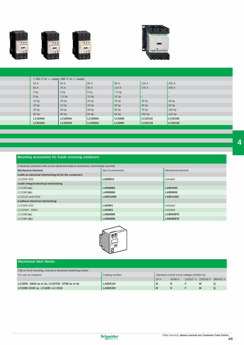
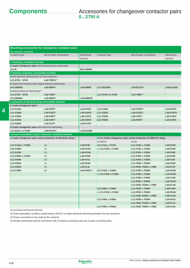
Mounting accessories for changeover contactor pairs(for customer assembly)Contactor type Set of power connections Mechanical Contactor type Set of power connections Mechanical
interlock interlock2 contactors, vertically mounted� 4-pole changeover pairs with locking device componentsLC1-B EZ2-LB06012 identical contactors, horizontally mounted� with electrical interlocking kit for the contactorsLC1-DT20…DT40 LAD-T9R1V (1)
� mechanical interlock with integral electrical interlockingLP1-D80004 LA9-D8070 LA9-D8002 LC1-D115004 LA9-D11570 LA9-D11502� without electrical interlocking (2)
LC1-DT20…DT32 LAD-T9R1 (2) LC1-DT40 and DT60 LAD-T9R2 (2)
LP1-D80004 LA9-D8070 LA9-D80978 2 contactors of identical rating, horizontally mounted� 4-pole changeover pairsLC1-F1154 LA9-FF977 LA9-FF970 LC1-F1504 LA9-F15077 LA9-FF970LC1-F1854 LA9-FG977 LA9-FG970 LC1-F2254 LA9-F22577 LA9-FG970LC1-F2654 LA9-FH977 LA9-FJ970 LC1-F3304 LA9-FJ977 LA9-FJ970LC1-F4004 LA9-FJ977 LA9-FJ970 LC1-F5004 LA9-FK977 LA9-FJ970LC1-F6304 LA9-FL977 LA9-FL970� 3-pole changeover pairs with electrical interlockingLC1-D115 and D150 LA9-D11571 LA9-D11502reversers assembled using 2 contactors, vertically mounted� 4-pole changeover pairs using contactors of identical rating (3) � 3 or 4-pole changeover pairs using contactors of different rating
At bottom At topLC1-F1154 or F1505 (3) LA9-FF4F LC1-F115 or F1154 LC1-F185 or F1854 LA9-FG4FLC1-F1854 (3) LA9-FG4G or LC1-F150 or F1504 LC1-F225 or F2254 LA9-FG4FLC1-F2254 (3) LA9-FG4G LC1-F265 or F2654 LA9-FH4FLC1-F2654 or F3304 (3) LA9-FH4H LC1-F300 or F3304 LA9-FH4FLC1-F4004 (3) LA9-FJ4J LC1-F400 or F4004 LA9-FJ4FLC1-F5004 (3) LA9-FK4K LC1-F500 or F5004 LA9-FK4FLC1-F6304 (3) LA9-FL4L LC1-F630, F6304 or F800 LA9-FL4FLC1-F7804 (4) LA9-FX971 (4) LC1-F185 or F1854 LC1-F265 or F2654 LA9-FH4G
or LC1-F225 or F2254 LC1-F330 or F3304 LA9-FH4GLC1-F400 or F4004 LA9-FJ4GLC1-F500 or F5004 LA9-FK4GLC1-F630, F6304 or F800 LA9-FL4G
LC1-F265 or F2654 LC1-F400 or F4004 LA9-FJ4Hor LC1-F330 or F3304 LC1-F500 or F5004 LA9-FK4H
LC1-F630, F6304 or F800 LA9-FL4HLC1-F400 or F4004 LC1-F500 or F5004 LA9-FK4J
LC1-F630, F6304 or F800 LA9-FL4JLC1-F500 or F5004 LC1-F630, F6304 or F800 LA9-FL4K
(1) Including mechanical interlock. (2) Order separately 2 auxiliary contact blocks LAD-N•1 to obtain electrical interlocking between the two contactors. (3) Power connections to be made by the customer. (4) Double mechanical interlock mechanism with 2 interlock connecting rods and 4 power connecting links.
Accessories for changeover contactor pairs0…2750 A
Components
38
Other versions: please consult our Customer Care Centre.4/394/39
4
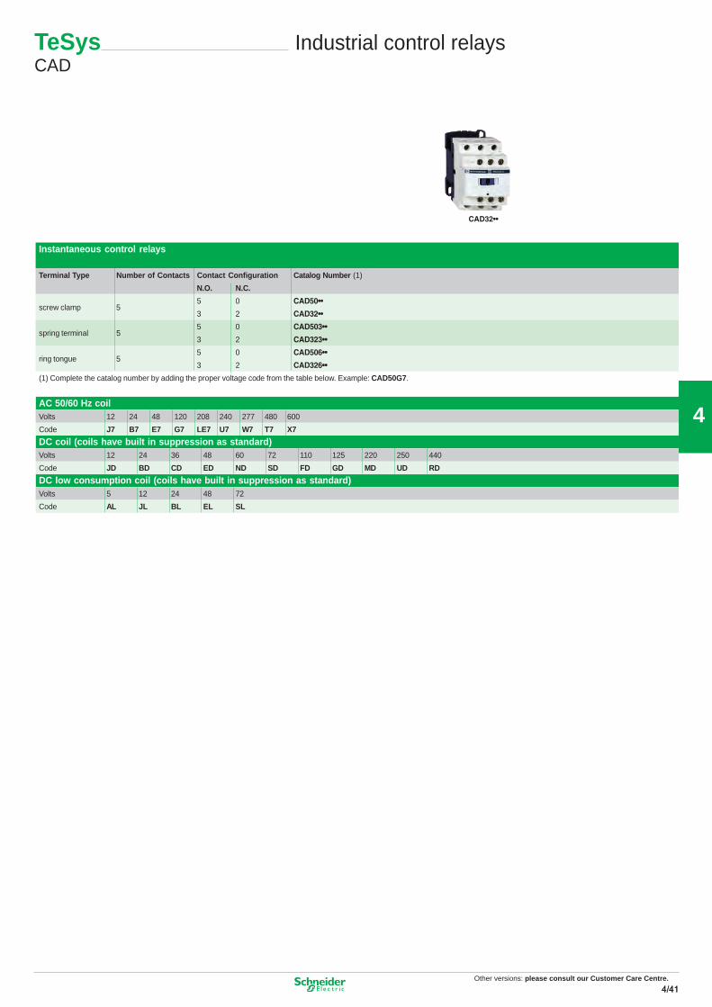
Industrial control relaysTeSys CA2K, CA3K and CA4K
DC coil (coils have built in suppression as standard)Volts 12 24 36 48 60 72 110 125 220 250 440
Code JD BD CD ED ND SD FD GD MD UD RD
DC low consumption coil (coils have built in suppression as standard)Volts 5 12 24 48 72
Code AL JL BL EL SL
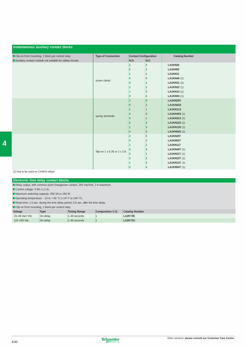
Instantaneous control relays
Terminal Type Number of Contacts Contact Configuration Catalog Number (1)
N.O. N.C.
5 0 CAD50••screw clamp 5
3 2 CAD32••
5 0 CAD503••spring terminal 5
3 2 CAD323••
5 0 CAD506••ring tongue 5
3 2 CAD326••
(1) Complete the catalog number by adding the proper voltage code from the table below. Example: CAD50G7.
CAD32••
CAD503••
MOT
OR
Other versions: Please consult our Customer Care Centre.
41
Other versions: please consult our Customer Care Centre.4/42
4
Instantaneous auxiliary contact blocks (for use in normal operation environments)
Number of Contacts Max. Number per Device (clip-on mounting) Termination Type Contact Composition Catalog Number
Front Left Side Only N.O. N.C.
2 0 LADN20
12 – Screw Clamp 1 1 LADN11
0 2 LADN02
2 0 LADN203
11lanimreT gnirpS–12 LADN113
0 2 LADN023
2 0 LAD8N20
11pmalC wercS)secived CD rof ton( 1–2 LAD8N11
0 2 LAD8N02
4 0 LADN40
3 1 LADN31
22pmalC wercS–14 LADN22
1 3 LADN13
0 4 LADN04
4 0 LADN403
3 1 LADN313
22lanimreT gnirpS–14 LADN223
1 3 LADN133
0 4 LADN043
22pmalC wercS–14 LADC22 (4)
22lanimreT gnirpS–14 LADC223 (4)
Instantaneous auxiliary contact blocks with dust and damp protected contacts (for use in particularly harsh industrial environments)ataCnoitisopmoC tcatnoCeciveD rep rebmuN .xaMstcatnoC fo rebmuN log Number
Time delay auxiliary contact blocksNumber and Type Max. Number per Device Time Delay Type Termination Type Range Catalog Numberof Contacts Front Mounting
0.1 to 3 sec. (2) LADT0
pmalc wercsyaleD-nO1.O.N 1 dna .C.N 10.1 to 30 sec. LADT2
10 to 180 sec. LADT4
1 to 30 sec. (3) LADS2
0.1 to 3 sec. (2) LADT03
lanimret gnirpsyaleD-nO1.O.N 1 dna .C.N 10.1 to 30 sec. LADT23
10 to 180 sec. LADT43
1 to 30 sec. (3) LADS23
0.1 to 3 sec. (2) LADR0
.ces 03 ot 1.0pmalc wercsyaleD-ffO1.O.N 1 dna .C.N 1 LADR2
10 to 180 sec. LADR4
0.1 to 3 sec. (2) LADR03
.ces 03 ot 1.0lanimret gnirpsyaleD-ffO1.O.N 1 dna .C.N 1 LADR23
10 to 180 sec. LADR43
(2) With extended scale from 0.1 to 0.6 s.
(3) With switching time of 40 ms ± 15 ms between opening of the N.C. contact and closing of the N.O. contact.(4) Includes 1 N.O. & 1 N.C. overlapping contact
42
Other versions: please consult our Customer Care Centre.4/434/43


![hey my web app is slow wheres the problemcarehart.org/presentations/hey_my_web_app_is_slow_wheres_the_problem.pdf, Z>/ Z , Zd U Z , Zd , Z>/ Z , Zd XKZ' } µ Z o ] Z , Z>/ Z , Zd U](https://static.documents.pub/doc/80x56/5f8b29c49f15817f370a5fc5/hey-my-web-app-is-slow-wheres-the-z-z-zd-u-z-zd-z-z-zd-xkz.jpg)


