MOTOR CONTROLLER INTEGRATED CIRCUITS TRINAMIC Motion Control GmbH & Co. KG Hamburg, Germany DC Motor Control with TMC4671 Table of Contents 1 DC MOTOR CLOSED LOOP CONTROL .................................................................................................................. 1 1.1 DC MOTOR CONTROL CONFIGURATION................................................................................................................... 1 2 TMC4671 EVALUATION BOARDS FOR APPLICATION NOTE......................................................................... 2 2.1 DC MOTOR TURNING.............................................................................................................................................. 2 2.2 SELECT DC MOTOR TYPE ........................................................................................................................................ 2 3 SETUP ADC FOR MEASUREMENT OF CURRENT ................................................................................................ 3 3.1 ADC DELTA SIGMA PARAMETER – INITIAL BASE PARAMETERS .............................................................................. 3 3.2 PWM ENGINE AND ASSOCIATED MOTOR CONNECTORS .......................................................................................... 4 3.3 DC MOTOR SETUP WITH TMCL-IDE AND ITS WIZARDS - COIL ............................................................................. 6 4 DISCLAIMER ............................................................................................................................................................. 11 5 REVISION HISTORY ............................................................................................................................................... 11 6 REFERENCES .............................................................................................................................................................. 11 1 DC Motor Closed Loop Control When using the TMC4671 for closed loop DC motor control, one current controller is used for torque control while the coordinate transformations required for FOC are skipped. Servo control functions as velocity control and position control of DC motors are similar to two-phase stepper motors and three-phase permanent magnet synchronous motors. The TMC4671 hardware provides an ADC engine, an encoder engine, PI controllers for closed loop current control, velocity control, position control, and a PWM engine usable in a unified way for DC motor control. 1.1 DC Motor Control Configuration The base for torque control of a DC motor enfolds configuration of analog digital converter ADC for current measurement, optional PWM adjustment, and the essential parameterization of P parameter and I parameter of the PI closed loop current controller. DC motor control of the TMC4671 is selected by the dedicated DC motor type control mode. A proper setup of closed loop current control is essential when using closed loop velocity control. For velocity control, one needs to set up some parameters of the position sensor. The TMC4671 uses a position sensor to measure the speed. A proper setup of closed loop current control together with a proper setup of velocity control is essential when using position control. The TMC4671 is equipped with integrated limiters to configure save operation area even on faults caused by wrong configuration. These limiters are useful especially during initial setup. Valid for TMC4671 The TMC4671 hardware controller performs Field Oriented Control (FOC) for two-phase stepper motors and for three-phase permanent magnet synchronous motors (PMSM) and it supports DC motor control. Why TMC4671 for DC motor servo control? The TMC4671 provides hardware closed loop torque control, velocity control, and position control even for DC motors decoupling motor control from application.
Transcript
MOTOR CONTROLLER INTEGRATED CIRCUITS
TRINAMIC Motion Control GmbH & Co. KG Hamburg, Germany
DC Motor Control with TMC4671
Table of Contents 1 DC MOTOR CLOSED LOOP CONTROL .................................................................................................................. 1
1.1 DC MOTOR CONTROL CONFIGURATION ................................................................................................................... 1
2 TMC4671 EVALUATION BOARDS FOR APPLICATION NOTE ......................................................................... 2
2.1 DC MOTOR TURNING .............................................................................................................................................. 2 2.2 SELECT DC MOTOR TYPE ........................................................................................................................................ 2
3 SETUP ADC FOR MEASUREMENT OF CURRENT ................................................................................................ 3
3.1 ADC DELTA SIGMA PARAMETER – INITIAL BASE PARAMETERS .............................................................................. 3 3.2 PWM ENGINE AND ASSOCIATED MOTOR CONNECTORS .......................................................................................... 4 3.3 DC MOTOR SETUP WITH TMCL-IDE AND ITS WIZARDS - COIL ............................................................................. 6
5 REVISION HISTORY ............................................................................................................................................... 11
1 DC Motor Closed Loop Control When using the TMC4671 for closed loop DC motor control, one current controller is used for torque control while the coordinate transformations required for FOC are skipped. Servo control functions as velocity control and position control of DC motors are similar to two-phase stepper motors and three-phase permanent magnet synchronous motors. The TMC4671 hardware provides an ADC engine, an encoder engine, PI controllers for closed loop current control, velocity control, position control, and a PWM engine usable in a unified way for DC motor control.
1.1 DC Motor Control Configuration The base for torque control of a DC motor enfolds configuration of analog digital converter ADC for current measurement, optional PWM adjustment, and the essential parameterization of P parameter and I parameter of the PI closed loop current controller. DC motor control of the TMC4671 is selected by the dedicated DC motor type control mode. A proper setup of closed loop current control is essential when using closed loop velocity control. For velocity control, one needs to set up some parameters of the position sensor. The TMC4671 uses a position sensor to measure the speed. A proper setup of closed loop current control together with a proper setup of velocity control is essential when using position control. The TMC4671 is equipped with integrated limiters to configure save operation area even on faults caused by wrong configuration. These limiters are useful especially during initial setup.
Valid for TMC4671 The TMC4671 hardware controller performs Field Oriented Control (FOC) for two-phase stepper motors and for three-phase permanent magnet synchronous motors (PMSM) and it supports DC motor control. Why TMC4671 for DC motor servo control? The TMC4671 provides hardware closed loop torque control, velocity control, and position control even for DC motors decoupling motor control from application.
Application Note AN025 (V0.99 / 2018-MAR-29) 2
www.trinamic.com
An important fault that might damage a motor or a power supply is a wrong sign of current measurement. With that, the current controller opens the PWM duty cycle up to 100%. With a programmable limiter, one can clip the PWM duty cycle to save operation where the resulting current is limited be the inner resistance of the motor. One the other side, this limiter limits the reachable performance of the motor.
2 TMC4671 Evaluation Boards for Application Note The evaluation kit used used as exemplary hardware platform configuration for this application note is Landungsbruecke v1.2 + TMC4671-EVAL v.1.1 + TMC-UPS-10A/70V-EVAL v.1.1 + DC Motor resp. a coil with an inductance L = 1 mH and resistance of 1 Ohm with a 24 V power supply. A coil is useful for emulating a blocked DC motor for initial setup of the closed loop current regulation.
2.1 DC Motor Turning Why initially turn the DC motor open loop? Initial, one needs to turn the motor open loop to check the current measurement for the motor, to check the association between ADC channel selection and DC motor terminals and to adjust the ADC scaling parameter and the ADC offset parameter. To turn a DC motor open-loop one just needs to apply a supply voltage VM to the DC motor. Together with PWM the effective voltage U applied to the motor is U = Vm * PWMdutyCycle[%]. For DC motor mode, the PWM duty cycle of the TMC4671 is programmed via UQ_EXT value of register UQ_UD_EXT where the UQ_EXT is a 16 bit signed value with the sign representing the sign of the effective voltage applied to the motor. The Upwm[V] = VM[V] * UQ_EXT[-32767, …, 0, …, +32767] is the effective voltage between the terminals of the PWM power stage.
2.2 Select DC Motor Type
Choose Motor Type = 0 for DC motor control. The PWM is choppering even in Motor Type = 0 mode but with zero effective coil voltage between terminals. This is to support boot-strapping charge pump of gate drivers. Choose Motor Type = 1 for DC motor with number of pole pairs NPP = 1. The number of pole pairs is not relevant for DC motor control but with that, electrical angles are same as mechanical angels when measuring angles with encoders. The motor type = 0 configures the PWM assigning the terminals U and V for the DC motor (Figure 3.1).
0 : no motor (PWM choppers in zero voltage mode) 1 : DC motor 2 : two-phase permanent magnet synchronous motor (stepper motor) 3 : three-phase permanent magnet synchronous motor (PMSM, brushless motor)
2.2.1 DC Motor Turning – Open Loop for Current Measurement Setup For open loop motor turning one applies PWM with a programmed duty cycle for the two half bridges with the DC motor connected between the terminals U and V. The supply voltage together with the PWM duty cycle determines the speed of motor. For FOC2 and FOC3 the UD_EXT is used to turn the motor open loop to determine the D direction of the current. In contrast to FOC3 and FOC2, for the DC motor - named FOC1 because the motor mechanically make FOC by its mechanical commutator brushes - the UQ_EXT is used turn the DC motor because the current through the DC motor generates torque similar to the torque generating current IQ in case of FOC2 and FOC3.
Application Note AN025 (V0.99 / 2018-MAR-29) 3
www.trinamic.com
2.2.2 DC Motor Turning – Closed Loop with PI Regulator For closed loop current control, a PI regulator controls the current by measuring the actual current and regulating the difference to the desired target current to zero. Initial, the P and I parameter of the PI regulator should be set to zero. First, the P parameter should be incremented with temporarily set I = 0 during determination of P parameter until the PI regulator reaches half of the desired target current. With a determined P parameter, the parameter I should be incremented until the PI regulator reaches the full desired target current. With that, one has an initial setup for the current regulation. The magnitude of the parameter I determines how fast the PI current regulator reaches the desired target current. A too large parameter I causes control loop oscillations. A good initial choice of I parameter for PI current controller setup is an I parameter that results in 1/8 of current change in time dII/dt comparted to the current change in time dIL/dt = UL/L of the inductance L of the motor while the P is temporarily set to 0 for determination of I parameter. To give an example: At t=0, a coil with L = 1 mH, and supply voltage 24V gives a dIL/dt = 24000A/s. If a TMC4671 with TMC-UPS-10A/70V power stage and 24V supply voltage gives and current changes in time of 3A/s for I=1 one could initially set I = 1/8 * 24000A/3A = 1000.
3 Setup ADC for Measurement of Current The TMC4671 supports two parallel sampling ADC channels for motor current measurement. For DC motor current measurement, the first channel ADC_I0_RAW is associated to measure the current of the DC motor. Some base ADC parameter need to be initialized.
3.1 ADC Delta Sigma Parameter – Initial Base Parameters The TMC4671 is equipped with internal Delta Sigma ADCs. The Delta Sigma ADC of the TMC4671 provide programmable filtering of input signals to adjust resolution vs. speed. The Delta Sigma ADCs are organized in two groups to enable different resolutions and speeds for these groups. The group A is for primarily for current measurement. The group B is primarily for processing of analog encoder signals. The the following default settings fit for most standard applications and are useful as initial parameter settings. Those settings are initialized by the TMCL-IDE Wizzard by Clicking on Default Settings.
ADDR Address Name Data Function
0x04 dsADC_MCFG_B_MCFG_A 0x00130013 ADC configuration group B and A
0x05 MCLK_A 0x20000000 Delta Sigma Clock A
0x06 MCLK_B 0x00000000 Delta Sigma Clock B off
0x07 dsADC_MDEC_B_MDEC_A 0x01000100 Deciamtion for B & A
0x0A ADC_I_SELECT 0x14000300 Select ADC channel for DC motor
0x1B MOTOR_TYPE_N_POLE_PAIRS 0x00010001 DC motor type, number of pole pairs
0x24 UQ_UD_EXT 0x00000000 UQ_EXT for PWM duty cycle, 1st zero
3.1.1 Adjust ADC Offsets and ADC Scaling and Sign The integrated ADCs deliver unsigned raw ADC values (ADC_RAW) within the 16 bit unsigned range 0 … 65535. The PI current controller needs scaled and offset corrected signed ADC values within the 16 bit signed range of -32767 … +32767 to perform closed loop current control. Similar to FOC2 and FOC3, it is essential to set correct ADC scale parameter, and correct ADC offset parameter for real time correction by the integrated ADC scaler and ADC offset compensator.
Application Note AN025 (V0.99 / 2018-MAR-29) 4
www.trinamic.com
Closed loop current control of DC motor needs correct association between applied voltage and measured current. For positive voltage UQ, a positive current IQ needs to be measured. For negative voltage -IQ, a negative current –IQ needs to be measured.
3.1.1.1 Measure Zero Current to Determine ADC and Sense Amplifier Offset
First, one needs to measure the zero current to determine the offset of ADC and sense amplifier.
0x03 ADC_RAW_ADDR 0x0000000 Set ADC RAW address to read ADC_I0_RAW
0x02 ADC_RAW_DATA ADC raw data Read actual ADC raw data
0x1A PWM_SV_CHOP 0x0000007 Switch PMW_ON
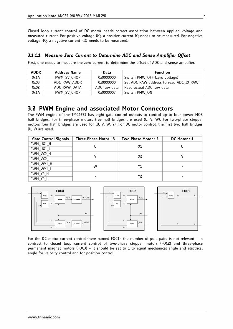
3.2 PWM Engine and associated Motor Connectors The PWM engine of the TMC4671 has eight gate control outputs to control up to four power MOS half bridges. For three-phase motors tree half bridges are used (U, V, W). For two-phase stepper motors four half bridges are used for (U, V, W, Y). For DC motor control, the first two half bridges (U, V) are used.
Gate Control Signals Three-Phase-Motor : 3 Two-Phase-Motor : 2 DC Motor : 1
PWM_UX1_H U X1 U
PWM_UX1_L
PWM_VX2_H V X2 V
PWM_VX2_L
PWM_WY1_H W Y1 -
PWM_WY1_L
PWM_Y2_H - Y2 -
PWM_Y2_L
FOC2
PARK
PIDD
PIDQ
iPARK
0
IT
IQ
ID
UQ
UD
Ia, Ib
Ua, Ub
PHI
FOC3
CLARKEPARK
iCLARKE
PIDD
PIDQ
iPARK
0
IT
IQ
ID
UQ
UD
IU, IV, IWIa, Ib
Ua, Ub UU, UV, UW
PHI
FOC1
PIDQ
IT
IQ
UQ
Ia
Ua
For the DC motor current control (here named FOC1), the number of pole pairs is not relevant – in contrast to closed loop current control of two-phase stepper motors (FOC2) and three-phase permanent magnet motors (FOC3) – it should be set to 1 to equal mechanical angle and electrical angle for velocity control and for position control.
Application Note AN025 (V0.99 / 2018-MAR-29) 5
www.trinamic.com
Figure 3.1 DC Motor Connection to TMC4671
Application Note AN025 (V0.99 / 2018-MAR-29) 6
www.trinamic.com
3.3 DC Motor Setup with TMCL-IDE and its Wizards - Coil
3.3.1 Select TMC4671
3.3.2 Start TMCL-IDE Wizard – Click the Weasel
Application Note AN025 (V0.99 / 2018-MAR-29) 7
www.trinamic.com
3.3.3 TMCL-IDE Wizard – Introduction
3.3.4 TMCL-IDE Wizard – Main Settings – Set Defaults for DC Motor
Set Number of Pole Pairs = 1 for possible later use of encoders.
Application Note AN025 (V0.99 / 2018-MAR-29) 8
www.trinamic.com
3.3.5 TMCL-IDE Wizard – Open Loop Settings
Use UQ_EXT to set the PWM duty cycle for the DC motor to run it open loop. Start with small values. The range of UQ_EXT is -32767, …, 0,…, +32767 associated with PWM duty cycle -100%, …, 0%, …, +100% where -100% stands for negative supply voltage and +100% stands for positive supply voltage. For initial ADC setup set UQ_EXT = 0 and use a coil with inductance L[mH] resistance R[Ohm] according to your DC motor or block your DC motor that it does not turn. With that, one can set up the current measurement and the PI closed loop current control.
3.3.6 TMCL-IDE Wizard – ADC Selection
Set ADC_I0_SELECT = ADC_SD_I0_RAW, set ADC_I_UX = UX, and load Sigma Delta Defaults.
Application Note AN025 (V0.99 / 2018-MAR-29) 9
www.trinamic.com
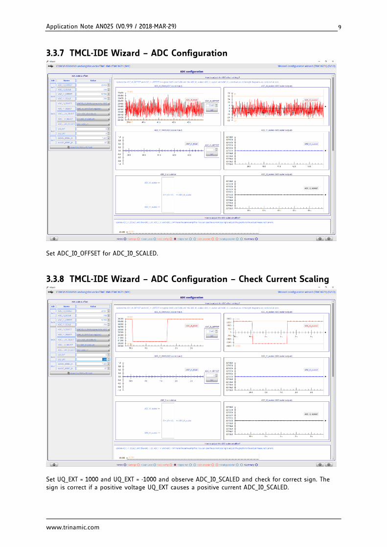
3.3.7 TMCL-IDE Wizard – ADC Configuration
Set ADC_I0_OFFSET for ADC_I0_SCALED.
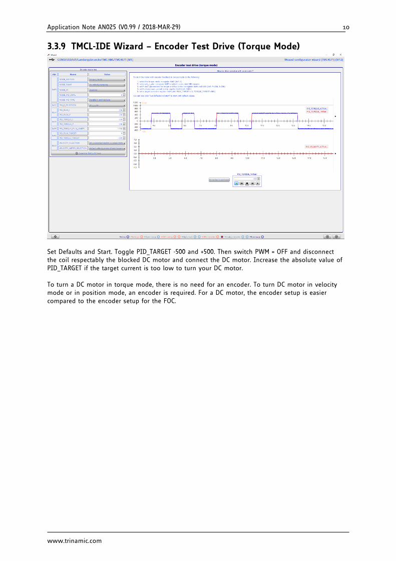
3.3.8 TMCL-IDE Wizard – ADC Configuration – Check Current Scaling
Set UQ_EXT = 1000 and UQ_EXT = -1000 and observe ADC_I0_SCALED and check for correct sign. The sign is correct if a positive voltage UQ_EXT causes a positive current ADC_I0_SCALED.
Application Note AN025 (V0.99 / 2018-MAR-29) 10
www.trinamic.com
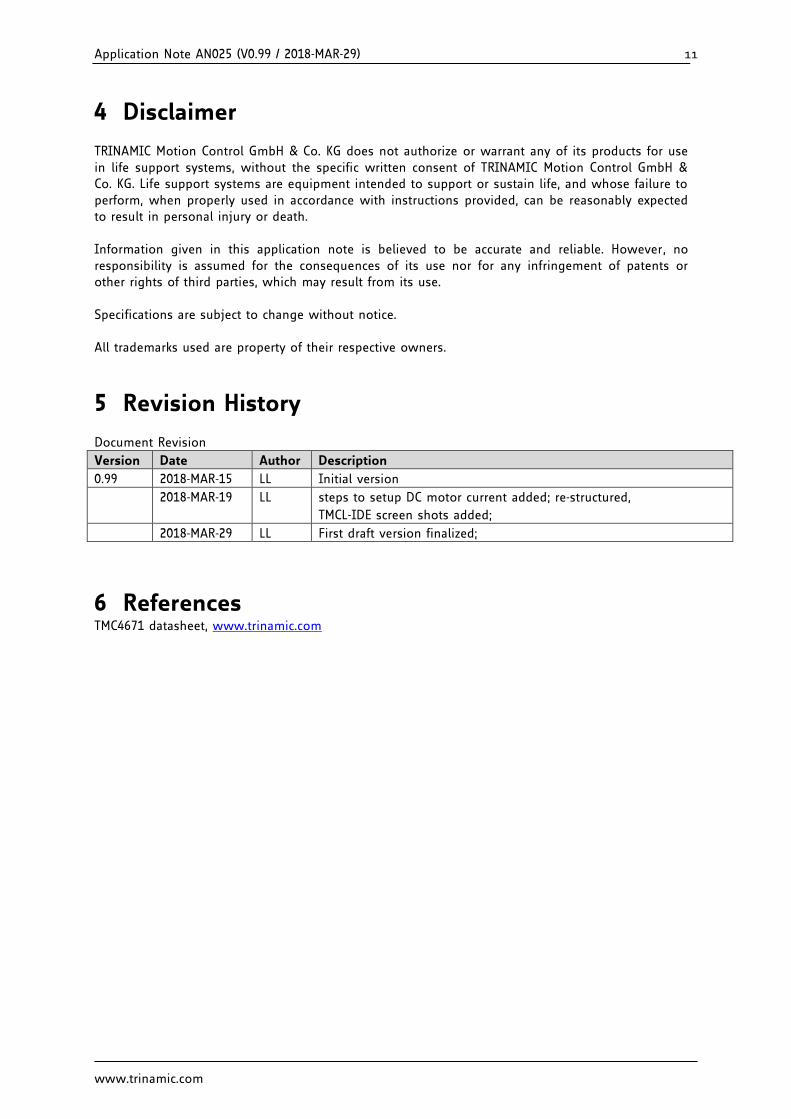
3.3.9 TMCL-IDE Wizard – Encoder Test Drive (Torque Mode)
Set Defaults and Start. Toggle PID_TARGET -500 and +500. Then switch PWM = OFF and disconnect the coil respectably the blocked DC motor and connect the DC motor. Increase the absolute value of PID_TARGET if the target current is too low to turn your DC motor. To turn a DC motor in torque mode, there is no need for an encoder. To turn DC motor in velocity mode or in position mode, an encoder is required. For a DC motor, the encoder setup is easier compared to the encoder setup for the FOC.
Application Note AN025 (V0.99 / 2018-MAR-29) 11
www.trinamic.com
4 Disclaimer TRINAMIC Motion Control GmbH & Co. KG does not authorize or warrant any of its products for use in life support systems, without the specific written consent of TRINAMIC Motion Control GmbH & Co. KG. Life support systems are equipment intended to support or sustain life, and whose failure to perform, when properly used in accordance with instructions provided, can be reasonably expected to result in personal injury or death. Information given in this application note is believed to be accurate and reliable. However, no responsibility is assumed for the consequences of its use nor for any infringement of patents or other rights of third parties, which may result from its use. Specifications are subject to change without notice. All trademarks used are property of their respective owners.
5 Revision History Document Revision
Version Date Author Description
0.99 2018-MAR-15 LL Initial version
2018-MAR-19 LL steps to setup DC motor current added; re-structured,