437 Motor Protection g Multilin Digital Energy • Flexible Protection, Control, and Communication options to suit Low Voltage Motor applications • Small footprint designed specifically for IEC and NEMA MCC applications • Integrated pushbuttons and LED indicators reduce external components and wiring • Flexible DIN rail mounting • Multiple communication protocols allows simple integration into monitoring and control systems. • Optional control panel provides local control • Low Voltage Three-Phase AC Motors • MCC and standalone Panel Mount Applications • IEC NEMA Motor Control Center (MCCs) • Process control applications • System architecture requiring multiple simultaneous communications • FVNR, FVR, two speed Protection and Control • Motor Thermal Model • Undercurrent • Current Unbalance • Acceleration Time • Sensitive Ground Fault • Built-in Starter Logic • FVNR, FVR, Two-Speed • Auto / Manual Control • Configurable Inputs • Power Fail Restart FEATURES MM200 MOTOR MANAGEMENT SYSTEM low voltage motor protection and control FEATURES APPLICATIONS KEY BENEFITS Metering & Monitoring • Current, Motor Loads, Thermal Capacity • Motor Running Time, Cause of Trip, Total Number of Trips • 1A / 5A combined CT inputs Communications • Networking through RS485 • Multiple protocols - Modbus RTU ODVA Compliant DeviceNet Internally powered Profibus • Simultaneous Communications User Interface • Optional Control Panel with control push buttons and LED status indicators • Includes EnerVista MM200 Setup software for simple programming and retrieval of system or trip information EnerVista TM Software • State of the art software for configuration and commissioning GE Multilin products • Graphical Logic Designer and Logic Monitor to simplify designing and testing procedures • Document and software archiving toolset to ensure reference material and device utilities are up-to-date
Transcript
437
Mot
or P
rote
ctio
n
g MultilinDigital Energy
• Flexible Protection, Control, and Communication options to suit Low Voltage Motor applications
• Small footprint designed specifically for IEC and NEMA MCC applications
• Integrated pushbuttons and LED indicators reduce external components and wiring
• Flexible DIN rail mounting• Multiple communication protocols allows simple integration
into monitoring and control systems.• Optional control panel provides local control
• Low Voltage Three-Phase AC Motors• MCC and standalone Panel Mount Applications• IEC NEMA Motor Control Center (MCCs)• Process control applications
• System architecture requiring multiple simultaneous communications
• FVNR, FVR, two speed
Protection and Control• Motor Thermal Model• Undercurrent • Current Unbalance• Acceleration Time• Sensitive Ground Fault• Built-in Starter Logic• FVNR, FVR, Two-Speed• Auto / Manual Control• Configurable Inputs• Power Fail Restart
FEATURES
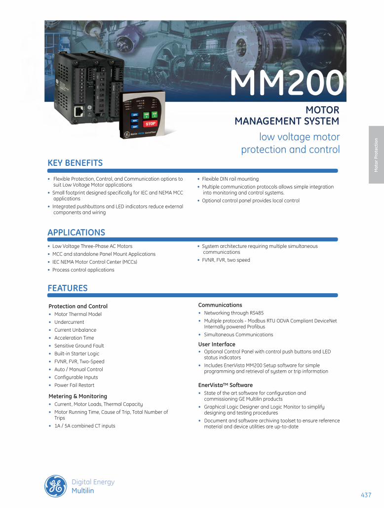
MM200MOTOR
MANAGEMENT SySTEMlow voltage motor
protection and control
FEATURES
APPLICATIONS
KEy BENEFITS
Metering & Monitoring• Current, Motor Loads, Thermal Capacity• Motor Running Time, Cause of Trip, Total Number of
User Interface• Optional Control Panel with control push buttons and LED
status indicators• Includes EnerVista MM200 Setup software for simple
programming and retrieval of system or trip information
EnerVistaTM Software• State of the art software for configuration and
commissioning GE Multilin products• Graphical Logic Designer and Logic Monitor to simplify
designing and testing procedures• Document and software archiving toolset to ensure reference
material and device utilities are up-to-date
438438438
MM200 Motor ManagerM
otor
Pro
tect
ion
www.GEDigitalEnergy.com
Protection and ControlThe MM200 is a digital motor protection and control system, designed for Low Voltage motor applications. Compact and powerful, the MM200’s protection can be scaled to the specific requirements of your system.
Motor Thermal Model
To provide optimal protection and maximize run time, the MM200 employs an advanced thermal model, consisting of four key elements:
• Overload Curves
• Hot/Cold Safe Stall Ratio
• Motor Cooling Time Constants
• Thermal protection reset
Overload Curves
The MM200 thermal model can be programmed with one of 15 standard overload curves.
When properly selected to match the motor manufactures thermal damage curves, the MM200 overload curve and Overload Pickup Level will determine the thermal capacity accumulated within the motor.
Functional Block Diagram
Hot / Cold Safe Stall Ratio
This ratio defines the steady state level of thermal capacity used (TCU) by the motor. This level corresponds to normal operating temperature of a fully loaded motor and will be adjusted proportionally if the motor load is lower then rated.
Motor Cool Time Constants
When the MM200 detects that the motor is running at a load lower then the overload pickup setpoint or the motor is stopped, it will start reducing the TCU value exponentially, based on the programmed cool time constants. As cooling occurs at different rates for stopped and running motors, two separate constants are used.
Mechanical Jam and Acceleration Time
These two elements are used to prevent motor damage during abnormal operating conditions such as driven load jams and excessively long acceleration times
Ground Fault
This function is designed to protect motors against phase to ground faults. The MM200 comes with one ground CT input intended for Core balance (Zero sequence)protection.
Current Unbalance
In addition to the Thermal model, current unbalance is available in the MM200 relay as an independent element with a built-in single phasing detection algorithm.
15CU RVE
1297
4
3
2
1
1010.1
10,000
1,000
100
TRIP
TIM
E(s
econ
ds)
10
1
Phase Current(Multiples of full load)
Full LoadSetpoint
15 Standard Curves available in the MM200
Device Number Function37 Undercurrent46 Current Unbalance49 Thermal Overload50G Ground Instantaneous Overcurrent51R Locked/Stalled Rotot, Mechanical Jam
ANSI Device Numbers & Functions
439439439
MM200 Motor Manager
Mot
or P
rote
ctio
n
www.GEDigitalEnergy.com
Advanced Device Health Diagnostics
The MM200 performs comprehensive device health diagnostic tests during startup and continuously at runtime to test its own major functions and critical hardware. These diagnostic tests monitor for conditions that could impact the MM200’s performance, evaluate the criticality of this impact and present device status via SCADA communications. Providing continuous monitoring and early detection of possible issues helps improve system availability by employing predictive maintenance
CommunicationsThe MM200 utilizes the most advanced communications technologies available today making it an easier and more flexible motor protection relay to use and integrate into new and existing infrastructures. Multiple communication ports and protocols allow control and easy access to information from the MM200. All communication ports are capable of communication simultaneously.
The MM200 supports the most popular industry standard protocols enabling easy, direct integration into HMI and electrical SCADA systems. Modbus RTU is provided standard with a RS485 networking port . The following optional protocols and communication ports are available:
• Fieldbus Protocol with dedicated port
- ODVA compliant DeviceNet
- Internally powered Profibus
Profibus DP
Providing a high degree of communication flexibility, the MM200 supports both Profibus DP-V0 and DP-V1. Profibus DP-V0 provides high-speed cyclic data exchange between distributed field devices and the Profibus master. In addition to the high-speed cyclic data communication with DP-V0, DP-V1 provides communication of acyclic data information between the slaves and the engineering workstation, which allows for independent diagnosing and fine-tuning of each slave on the network.
Undercurrent Protection
Undercurrent protection is standard in the MM200. providing additional protection while the motor is in the running state and any of the phase currents drop below the defined pick-up level for the durartion specified.
Power Fail Restart
The MM200 supports a Power Fail Restart element (PFR), which provides an undervoltage motor restart after a momentary power loss (dip). The undervoltage condition is detected by a digital input associated with an externally mounted voltage relay.
The PFR in combination with a voltage relay provides an undervoltage motor restart solution in applications such as; oil and gas, where process uptime is critical to the overall operation of the facility.
Thermistor
A single input from a motor winding thermistor is provided with the MM200. The MM200 can accept both positive temperature coefficient (PTC) and negative temperature coefficient (NTC) sensors. A thermistor level can be selected for both alarm and trip.
Monitoring and MeteringThe MM200 includes high accuracy metering of current signals. Current parameters are available as total RMS magnitude.
Digital Counters
The MM200 provides ten digital counters to aid in system analysis. The digital counters can be used for scheduling inspections on equipment, performing qualitative analysis of system problems and spotting trends.
Learned Data
Monitoring the motor ’s operating characteristics assists in determining the motor start parameters and is a critical tool for determining the operating characteristics of the system, motor and connected load.
Rapid Device Replacement
The MM200 supports Rapid Device Replacement , which is compatible with DeviceNet scanners that use Automatic Device Replacement (ADR) functionality. When Rapid Device Replacement is used in DeviceNet networks, this allows rapid change of MM200 devices with minimum process interruption.
When using Rapid Device Replacement, the MM200 can be replaced without the need to manually configure settings. The DeviceNet scanner will automatically recognize a new device and download the key protection, control and communication settings from the original MM200, reducing process downtime and manual setting file configuration.
EnerVistaTM SoftwareThe EnerVista™ Suite is an industry-leading set of software programs that simplifies every aspect of using the MM200 relay. The EnerVistaTM suite provides all the tools to monitor the status of the protected asset , maintain the relay, and integrate information measured by the MM200 into DCS or SCADA monitoring systems.
MM200 Dual Architecture Communication
440440440
MM200 Motor ManagerM
otor
Pro
tect
ion
www.GEDigitalEnergy.com
EnerVista™ Launchpad
EnerVista™ Launchpad is a powerful software package that provides users with all of the setup and support tools needed for configuring and maintaining GE Multilin products. The setup software within Launchpad allows configuring devices in real-time by communicating using serial, Ethernet, or modem connections, or offline by creating setting files to be sent to devices at a later time.
Included in Launchpad is a document archiving and management system that ensures critical documentation is up-to-date and available when needed. Documents made available include:
• Manuals
• Application Notes
• Guideform Specifications
• Brochures
• Wiring Diagrams
• FAQs
• Service Bulletins
Viewpoint Monitoring
Viewpoint Monitoring is a simple-to-use and full-featured monitoring and data recording software package for small systems. Viewpoint Monitoring provides a complete HMI package with the following functionality:
• Plug & Play Device Monitoring
• System Single-Line Monitoring & Control
• Annunciator Alarm Screens
• Trending Reports
• Automatic Event Retrieval
• Automatic Waveform Retrieval
Viewpoint Maintenance
Viewpoint Maintenance provides tools that will create reports on the operating status of the relay, simplify the steps to download fault and event data, and reduce the work required for cyber-security compliance audits.
EnerVista™ Integrator
EnerVistaTM Integrator is a toolkit that allows seamless integration of GE Multilin devices into new or existing automation systems. Included in EnerVistaTM Integrator is:
• OPC/DDE Server
• GE Multilin Drivers
• Automatic Event Retrieval
• Automatic Waveform Retrieval
Online Device Window: • Online communication to device• Relay designation• Online configuration of all relay setpoints• Communication to multiple devices• Copy online settings to files offline
Active Settings Window: • Simple drop down menu options for setting
parameters• Detailed view parameter set points
Offline File Window: • Create setting file templates• Copy and paste settings from one relay to
another• Copy offline settings to online devices
EnerVista MM200 Set-up
EnerVista setup software simplifies every aspect of using the MM200 relay. The EnerVista suite provides all the tools required to configure monitor & maintain the relay. Advanced communications support ensures easy integration into new or existing DCS scada systems.
441441441
MM200 Motor Manager
Mot
or P
rote
ctio
n
www.GEDigitalEnergy.com
The Hand Held Display (HHD) provides a rugged local interface for MM200 Motor Protection Systems where a local display is not used in the MCC.
The HHD provides a graphical color local interface to the MM200 Motor Protection Systems allowing local operators to view and change setting files and quickly access relay diagnostic information.
The HHD provides a clear and detailed view of all motor settings, diagnostic information and metering data available in the MM200 allowing local operators to make informed decisions on the motors operation.
3 Phase CT Inputs
RS485 Communications and Thermistor Input
• Sensitive Ground Fault• 2 Form A Outputs (5 Amps)• 1 Form C Outputs (5 Amps)
Optional FieldbusProtocols(ProfiBus or DeviceNet)
Power Supply and Digital Inputs:• 24 VDC Power Supply• 7 x 24 VDC Inputs (wet) • 60-300VAC Power Supply• 6x AC Inputs
Optional Control Panel Interface
12 LED Indicators:• Motor Status• Alarm Indication & trip• Communication Status• Additional user LEDs• Auto/Manual• % Motor Load
Front Panel Controls• Integrated Device Controls
User Interface
Top ViewSide View Front View
Dimensions
HandHeld Display (HHD)
4.437” (112.7 mm)
3.542” (90 mm)
3.100” (78.7 mm)
442442442
MM200 Motor ManagerM
otor
Pro
tect
ion
www.GEDigitalEnergy.com
Wiring Diagrams
LO and HI inputs - see next page -
443443443
MM200 Motor Manager
Mot
or P
rote
ctio
n
www.GEDigitalEnergy.com
Wiring Diagrams (Cont)
Technical Specifications
PROTECTIONTHERMAL MODELStandard Curve Time Multiplier:
Timing Accuracy: ±500 msElements: Trip and AlarmCURRENT UNBALANCEUnbalance: (Imax - Iav) / Iav, if Iav >= Ifla
(Imax - Iav) / Iflc, if Iav < IflaRange/Pickup Level:
4% to 40% steps of 1%
Time Delay: 1 to 60s in steps of 1Pickup Accuracy: ±2%Timing Accuracy: ±500msElements: Trip and AlarmUNDERCURRENTPickup Level: 1 to 100% of FLCTime Delay: 1 to 60 s in steps of 1Timing Accuracy: ±500msElements: Trip and AlarmMECHANICAL JAMPickup Level: 1.01 to 4.50 of FLA in steps of 0.01Time Delay: 0.1 to 30.0s in steps of 0.1Timing Accuracy: ±500msElements: TripGROUND FAULTPickup Level: 0.5 to 15.0A in steps 0.1 (CBCT)Time Delay: 0 to 10s in steps 0.1s (start)
0 to 5s in steps 0.1s (run) Alarm time delay on start/run: 0 to 60s in steps of 1s
Timing Accuracy: +100ms or ±0.5% of total timeElements: Trip and AlarmACCELERATION TIMERPickup: Iav > IcuttoffDropout: Iav < Ipu or Timer expiredTime Delay (force to running if expired):
0.5 to 250.0 s in steps of 0.10 to 5s in steps 0.1s (run)
Timing Accuracy: ±500ms or ±1.5% of total timeElements: Trip and Alarm
CERTIFICATIONISO: Manufactured under an ISO9001
registered systemconforms to EN60255-5, EN60255-27, EN60255-26, EN50263
Shock & Bump: IEC60255-21-2Siesmic: IEC60255-21-3Power magnetic Immunity:
IEC61000-4-8
Pulse Magnetic Immunity:
IEC61000-4-9
Damped Magnetic Immunity:
IEC61000-4-10
Voltage Dip & interruption:
IEC61000-4-11
Damped Oscillatory:
IEC61000-4-12
Voltage Ripple: IEC61000-4-17Ingress Protection: IEC60529Environmental (Cold):
IEC60068-2-1
Environmental (Dry heat):
IEC60068-2-2
Relative Humidity Cyclic:
IEC60068-2-30
Safety: UL508 / UL C22.2-14 / UL1053
ENVIRONMENTALTemperature Range *: Ambient Operating: -20°C to +60°C Ambient Storage: -40°C to +90°CHumidity: Up to 90% non-condensing @ 55CPollution degree: IIIP Rating Base Unit IP20, Control panel IP54
*Temperature range based on 1” around base unit
POWER SUPPLy SPECIFICATIONSPOWER SUPPLy (LO RANGE)Nominal 24 V DCRange 18 to 36 V DCPower Consumption 10 W typicalPOWER SUPPLy (HI RANGE)Nominal 120 to 240 V AC; 125 to 250 V DCRange 60 to 300 V AC (50 and 60 Hz); 84 to
250 V DCPower consumption 10 W typicalVoltage withstand 2 × highest nominal voltage for 10 ms
DC resistive, 30Vdc 5AOUTPUT RELAy BREAK CAPACITy (FORM_C)AC resistive, 120Vac:
5A (NO) 5A (NC)
AC resistive, 240Vac:
5A (NO) 8A (NC)
AC inductive, PF = 0.4 pilot duty:
2 40VA
DC resistive, 30Vdc 5A
INPUTSPHASE CURRENT INPUTSCT Primary: 0.5A to 1000ACT Secondary: 1A or 5A (Both supported as standard)Burden: 0.2VAConversion Range: 0.2 to 40 A (8x CT)Nominal Frequency: 50/60 HzFrequency Range: 40-70 HzAccuracy: (Ext CT) 2% of injected or 1% of 8xCTPAccuracy: (Direct) 2% of injected or 0.1ACT Withstand: 0.2 seconds at 100 x rated current
1.0 second at 50 x rated current2.0 seconds at 40 x rated currentcontinuous at 3 x rated current (40DegC)
SENSITIVE GROUND CURRENT INPUTCT Primary: 0.5A to 15AConversion Range: 0.5A to 15A, 2000:1 CBCTAccuracy: 0.1A (0.5A to 3.99A)
0.2A (4.0A to 15A)DIGITAL INPUTS X7Fixed Threshhold: 24VDCRecognition Time: 2 cycle recognitionContinuous Current Draw:
4mA
Type: Opto-isolated inputsExternal Switch: Wet ContactMax. Inputs Voltage: 30VDCDIGITAL INPUTS (HI)Nominal voltage 120 V AC to 240 V ACRecognition time 2 cyclesContinuous current draw
4 mA @120 V AC; 8 mA @ 240 V AC
Type opto-isolated inputsExternal switch wet contactVoltage range 65 V AC to 300 V AC
Please refer to MM200 Motor Manager Instruction Manual for complete technical specifications.
444444444
MM200 Motor ManagerM
otor
Pro
tect
ion
www.GEDigitalEnergy.com
MM200 * X * * * DescriptionControl Panel X None B Basic Control Panel, no USBPower Supply L 24 VDC H 60 - 300 VACCommunication 1 RS485 Modbus RTU + DeviceNet Slave 2 RS485 Modbus RTU + Profibus DP SlaveProtection S Standard Protection & Control
Ordering
• Viewpoint Engineer VPE-1
• Viewpoint Maintenance VPM-1
• Viewpoint Monitoring VP-1
Software for the MM200 • View Guideform specifications