Electric Actuator ETS Series New Product ACTUATOR FOR ELECTRIC MOTORS ETS SERIES New Products CC-1165A 7 Ball screw driven Motorless type Extensive line up Installation of familiar motor is available.
Transcript
Electric ActuatorETS Series
New Product
ACTUATOR FOR ELECTRIC MOTORS ETS SERIES
New Products
CC-1165A 7
Ball screw drivenMotorless type
Extensive line up
Installation of familiar
motor is available.
Suitable lead selection according to speed and load capacity(2 mm, 5 mm, 10 mm, 16 mm, 20 mm, 25 mm, 40 mm)
High rigidity by using parallel guide Low installation height oval type
Direct lubrication to guide and ball screw through grease oil fillerEasy maintenance and long life-span* Option
ETS SeriesVariety of line-up suitable for use applicationMax. load capacity : up to 150 kg Max. stroke : up to 1500 mm Max. speed : up to 2000 mm/s
Ball screw driven
Selectable from 8 sizes
Wide range of screw leads!
High rigidity body(ETS-12 or more size)
Easy Maintenance!
Outside direct Left turn-up Right turn-up Below turn-up Built-in
Installation direction of home position sensor and limit sensor and sensor dog selectable
Several brackets available. Manufacturer and installation direction selectable.
Inside sensor Inside sensor dog
Outside sensor Outside sensor dog
Selectable motor installation direction
Installation of familiar motor is available
Variety of sensor installation method!
* Option
* Option
The motor is not installed with this product. Please obtain and install and adjust the motor and driver by yourself.
General-purpose SSCNET
------
-----
-- -
-
--
--
---
---
--
-
--
--
CC-Link MECHATROLINK-Ⅱ
MECHATROLINK-Ⅲ
Device Net
EtherCAT
The motor is not installed with this product. Please obtain and install and adjust the motor and driver by yourself.
Availability list for motor manufacturer and field network
Mitsubishi Electric CorporationDelta Electronics, Inc.
SANYO DENKI CO.,LTD.YASKAWA ELECTRIC CORPORATIONKEYENCE CORPORATION
Panasonic CorporationOMRON Corporation
* Refer to table 3 on page 4 for the details.
Available - Not available
Selection guideTy
pe Model no.
Applicable motor
volume(W)
Body depth(mm)
Ballscrew precision grade: C7 Repeatability
(mm)
Max. load capacity (kg) Stroke(mm) and Max. speed(mm/s)*1Outer
diameter(mm)
Screw lead(mm)
Slid
er ty
pe
Bod
y si
ze: l
arge
Bod
y si
ze: s
mal
l
ETS-05 100 51 12
2
±0.02
10 7
5 10 3
10 5 1.5
ETS-06 100 65 12
2 30 15
5 30 10
10 15 5
ETS-10 100 102 16
5 50 12
10 30 8
16 22 5
20 18 3
ETS-12 100 102 16
5 50 12
10 30 8
16 22 5
20 18 3
ETS-13 200 135 16
5 70 17
10 47 12
16 30 6
20 24 4
ETS-14
200 135 16
5 95 27
10 75 18
16 44 7
20 35 6
400 135 16
5 110 33
10 88 22
16 48 10
20 40 8
ETS-17
400 170 20
5 120 40
10 110 30
20 75 14
40 35 7
750 170 20
5 120 50
10 120 40
20 83 25
40 50 10
ETS-22 750 22025
5 150 55
10 150 45
25 120 20
20 40 60 10
Horizontal Vertical
100
150
200
250
300
350
400
450
500
550
600
650
700
750
800
850
900
950
1000
1050
1100
1150
1200
1250
1300
1350
1400
1450
1500
mm
Intro 1
Selection guide
Type Model no.
Applicable motor
volume(W)
Body depth(mm)
Ballscrew precision grade: C7 Repeatability
(mm)
Max. load capacity (kg) Stroke(mm) and Max. speed(mm/s)*1Outer
diameter(mm)
Screw lead(mm)
Slid
er ty
pe
Bod
y si
ze: l
arge
Bod
y si
ze: s
mal
l
ETS-05 100 51 12
2
±0.02
10 7
5 10 3
10 5 1.5
ETS-06 100 65 12
2 30 15
5 30 10
10 15 5
ETS-10 100 102 16
5 50 12
10 30 8
16 22 5
20 18 3
ETS-12 100 102 16
5 50 12
10 30 8
16 22 5
20 18 3
ETS-13 200 135 16
5 70 17
10 47 12
16 30 6
20 24 4
ETS-14
200 135 16
5 95 27
10 75 18
16 44 7
20 35 6
400 135 16
5 110 33
10 88 22
16 48 10
20 40 8
ETS-17
400 170 20
5 120 40
10 110 30
20 75 14
40 35 7
750 170 20
5 120 50
10 120 40
20 83 25
40 50 10
ETS-22 750 22025
5 150 55
10 150 45
25 120 20
20 40 60 10
Horizontal Vertical
100
150
200
250
300
350
400
450
500
550
600
650
700
750
800
850
900
950
1000
1050
1100
1150
1200
1250
1300
1350
1400
1450
1500
mm
*1 Max. speed is estimated valve at 3,000rpm of installed motor. Max. speed has limitation by stroke. Do not operate faster than limited speed.
100 90 80 70 60
250 225 200 175 150
500 450 400 350 300
100 90 80 70 60
250 225 200 175 150
500 450 400 350 300
250 225
225
225
225
225
200
200
200
200
200
175
175
175
175
175
150
150
150
150
150
125
125
125
125
125
500 450
450
450
450
450
400
400
400
400
400
350
350
350
350
350
300
300
300
300
300
250
250
250
250
250
800 720
720
720
720
720
640
640
640
640
640
560
560
560
560
560
480
480
480
480
480
400
400
400
400
400
1000 900
900
900
900
900
800
800
800
800
800
700
700
700
700
700
600
600
600
600
600
500
500
500
500
500
250
500
800
1000
250
500
800
1000
250
500
800
1000
250
500
800
1000
250 225 200 175 150
500 450 400 350 300
1000 900 800 700 600
2000 1800 1600 1400 1200
250 225 200 175 150
500 450 400 350 300
1000 900 800 700 600
2000 1800 1600 1400 1200
250 225 200 175 150 125 100
500 450 400 350 300 250 200
1250 1125 1000 875 750 625 500
2000 1800 1600 1400 1200 1000 800 600
Intro 2
Electric driven actuator slider type
ETS Series Applicable motor size: 100W 200W 400W 750W
Specifications
[Applicable motor size:100W]
*1: Value at the time of acceleration/deceleration at 0.2 sec.*2: The stroke pitch is 50.
CAUTION:This product does not have motor. Please obtain and install and adjust the motor and driver by yourself.
Max.speed is estimated valve at 3,000rpm of installed motor. Thrust force and max. load capacity is estimated value at the rated torque of installed motor.
*1: Value at the time of acceleration/deceleration at 0.2 sec.*2: The stroke pitch is 50.
1
*1: Value at the time of acceleration/deceleration at 0.2 sec.*2: The stroke pitch is 50.
CAUTION:The motor is not installed with this product. Please obtain and install and adjust the motor and driver by yourself.
Max.speed is estimated valve at 3,000rpm of installed motor. Thrust force and max. load capacity is estimated value at the rated torque of installed motor.
Screw lead (refer to the following page table 1.)02 2mm05 5mm10 10mm16 16mm20 20mm25 25mm40 40mm
Stroke length (refer to the following page table 1.)010
upto 150From 100mm to 1500mm(50mm pitch) Indication is 1/10.
How to install the motor (refer to the following page table 2.)E External direct mountingD Bottom up mountingR Right side up mountingL Left side up mountingB Built-in type*
Motor mounting specs.M Select motor mounting specifications
from the table below.YP
Motor size (refer to the following page table 2.)1 100W2 200W4 400W8 750W
BrakeN No brakesB With brakes*
Origin sensor (1 pc.) (refer to the following page table 4.)N No sensorA Internal Motor-sideB Internal opposite Motor-sideC External Motor-side (attached shipment)D External opposite Motor-side (attached shipment)
Limit sensor (2) (refer to the following page table 4.)N No sensorA InternalB External (attached shipment)
Grease nipple (refer to the following page table 5.)N Body mounting direction Standard/ No grease nipplesD Body mounting direction Down/No grease nipplesR Grease nipple Right-sideL Grease nipple Left-side
A
B
C
D
E
F
G
H
I
J
<Example of model number>ETS-06-05040-EM1BCBD
Body size: width 65×height 56mm
Screw lead: 5mm
Stroke length: 400mm
Motor installation method: external direct installation
Motor mounting specification: Mitsubishi
Motor size: 100W
Brakes: equipped
Home position sensor: outside the motor-side
Limit-sensor: outside
Optional: No grease nipple
A
B
C
D
E
F
G
H
I
J
Motor mounting specs. (refer to table 3 on the next page.)E
* If the motor mounting direction is other than the "B (built-in type)", the actuator will have no brakes. In G select N (no brakes) in any case.
Maker 100W 200W 400W 750WMitsubishi Electric Corporation M M M MDelta Electronics, Inc. M M M MSANYO DENKI CO.,LTD. M M M MYASKAWA ELECTRIC CORPORATION Y Y Y YKEYENCE CORPORATION Y Y Y YPanasonic Corporation P P P POMRON Corporation M P P P
*1:Home position sensor and limit sensor are a set. Either is Nil, select Nil for the other. Example: Set of home sensor Nil and limit sensor Installed (internal / external) is not available. *2:ETS-10 is not available for the combination of home sensor B (internal, opposite side of motor) and limit sensor Installed (internal / external).Example: ETS-10-*-*BA* ......not available as model number*3:When the mounting direction of ETS-12 is R (mounting clockwise) or L (mounting counter-clockwise), the combination of home sensor A (internal, motor side) and limit sensor A (internal) is not available.Example: ETS-12-*-*R/L*AA* ......not available as model number*4:In case of mounting inside of sensor, users cannot adjust the position. (shipped pre-assembled)Before using the product, make sure that the product suits your needs. It is recommended to use the external sensor for locating the home position with an encoder.In case of mounting outside of sensor, users can adjust the position. (shipped pre-assembled)
Table 4 Home position sensor and limit sensor H I
ModelH Home position sensor (1 pc.) I Limit sensor (2 pc.)
Without *1Internal External
Without *1 Internal ExternalMotor side Opposite Motor side Motor side Opposite Motor side
Table3 Motor mounting specs., Recommended motor model No., and Rated output EE maker Motor (without brake) Motor (with brake) Rated output E maker Motor (without brake) Motor (with brake) Rated outputMitsubishi
*1:Servo motor ECMA series (brake mounting) manufactured by Delta Electronics, Inc. is not available for built-in.*2:Consult with CKD for mounting motors with model No. not listed in recommendation list above or motors manufactured by other manufacturers.
*1
" " Available, "-" Not available
*1:Grease nipples cannot be mounted on ETS-05 or 06.*2:Body mounting direction instructions for ETS-06. Select N (mounting direction standard) or D (mounting direction down).*3:Grease nipple mounting options for ETS-10 to 22. Select N (without), R (right), or L (left).
ModelJ Options
Built-in/External direct mountBottom side up Right side up Left side up
ETS-05 N only (Body mounting direction: Standard (Lower side only))ETS-06 N: Body mounting direction: Standard (Upper side φ4.5 counterbore), D: Body mounting direction: M5 from lower side bottom
ETS-10 to 22 N/R/L N/L N/R
Table 5 Motor mounting methods and options J
4
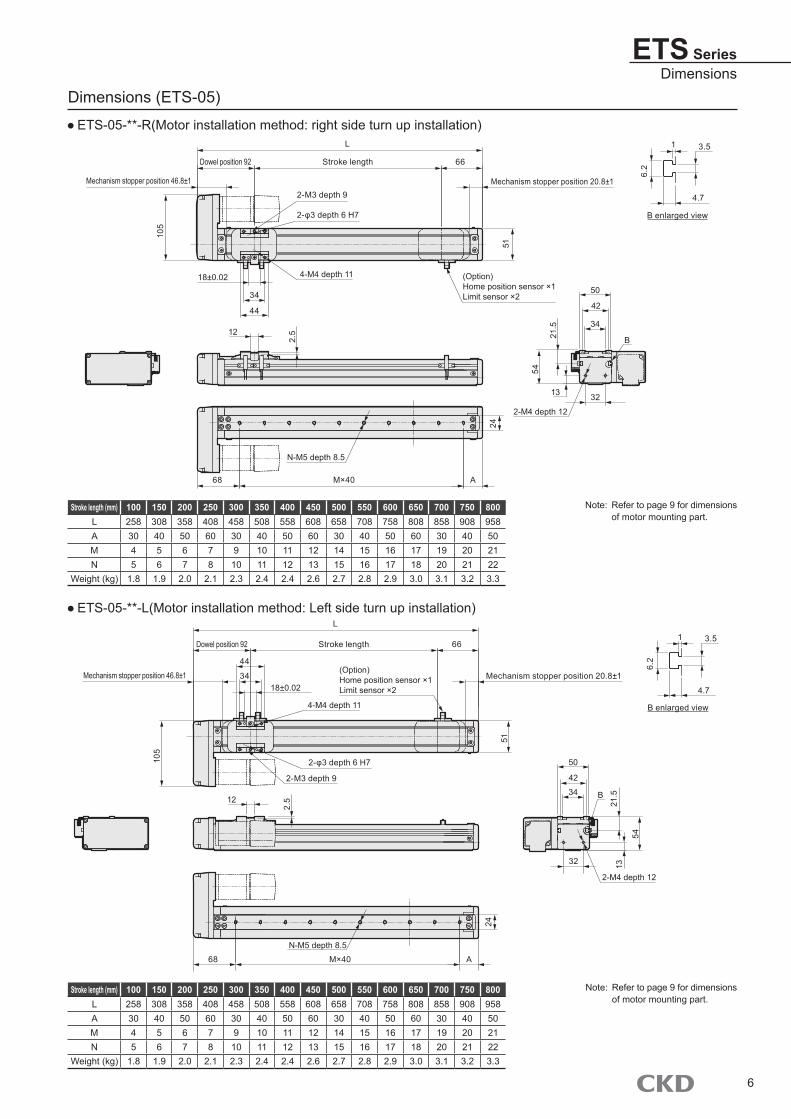
ETS Series
Dimensions (ETS-05)
ETS-05-**-E (how to install the motor: external direct installation)
ETS-05-**-D(Motor installation method: bottom-side up installation)
STEP-1Load capacity will change according to installation orientation and transferring speed. Select size and screw lead, referring to selection table (intro pages 1, 2) and specification table for each model (pages 1, 2).
Load capacity confirmation
STEP-2Calculate and confirm that tact time matches requirements by the following example. Select rotation speed and rotation acceleration and deceleration speed by specification tables of each model (page 1 and 2)
Tact time confirmation
Descriptions Symbol Unit Remarks
Set value
Setting speed V mm/s
Setting acceleration a mm/s2
Setting deceleration degree d mm/s2
Moving distance S mm
Calculated value
Arrival speed Vmax. mm/s =(2×a×d×S/(a+d))1/2
Effective speed Vb mm/s V and Vmax. smaller one
Acceleration hour Ta s = Vb/a <0.2 sec. or more>
Deceleration hour Td s = Vb/d <0.2 sec. or more>
Constant speed hour Tc s = Sc/Vb
Acceleration distance Sa mm =(a×Ta2)/2
Deceleration distance Sd mm =(d×Td2)/2
Constant speed distance Sc mm = S- (Sa + Sd)
Positioning time T s = Ta + Tc + Td
Do not use by speeds higher than specifications. Acceleration and deceleration setting by acceleration time and deceleration time changes depending on the set speed and the stroke length.
The velocity curve may be unattainable (unreachable due to set speed) by acceleration and deceleration speeds.
Compare by using Vmax and set speed. Make a comparison of by the Vmax. [con and] the set speed. Please use at more than 0.2 sec of acceleration/deceleration.
Confirm that actual moment is less than allowable moment and overhang amount
STEP-3 Allowable moment confirmation
Speedmm/s
Timesec
Positionmm
Acceleration zone Constant speed zone Deceleration zone
Effective speed: Vb
Arrival speed: Vmax.Accelerationa
Deceleration degree
d
Acceleration timeTa
Deceleration timeTd
Constant speed timeTc
Positioning time T
Acceleration distanceSa
Deceleration distanceSd
Constant speed distanceSc
Moving distance S
Selection guide
Allowable moment confirmation when in operation.
Confirm that actual moment is less than allowable moment (satisfies the following formula)
MT=W
Wmax+
MR1+MR2
MRmax+
MP1+MP2+MP3
MPmax+
MY1+MY2+MY3
MYmax<1
MT: combination of moment (must be less than 1)W: vertical weightingMR: rolling momentMP: pitching momentMY: yawing moment
Wmax: allowable loadMRmax, MPmax, MYmax: Refer page 35 to 38 for dynamic allowable moment.
ETS Series
"L" on page 36 should be less than allowable amount A, B, and C on pages from 37 to 40.
* Take all moments into consideration depending on the operating moment load.
35
ETS SeriesSelection guide
Vertical load W (N)
Rolling moment MR(N·m)
Pitching moment MP(N·m)
Yawing moment MY(N·m)
Body height (from the actuator bottom to the upper surface of the slider)
[Dynamic allowable moment and allowable overhang amount] Applicable motor size: 100W
Mounting orientation
LeadLoad
kgOverhang mm
A B CHorizontal 5
30 560 50 5050 310 27 27
1015 440 90 9025 250 50 5030 200 40 40
165 950 270 23010 480 130 11022 200 55 45
205 750 250 20010 370 120 9515 240 80 60
Side surface5
10 160 160 140020 75 75 65030 45 45 400
1010 130 140 69020 60 65 33030 40 40 210
165 230 250 75010 110 120 37022 45 50 160
205 220 250 65010 105 120 32015 65 75 210
Vertical5
5 310 - 31010 155 - 15512 130 - 130
104 360 - 3606 240 - 2408 180 - 180
161 1050 - 10502 525 - 5255 210 - 210
201 850 - 8502 425 - 4253 283 - 283
Mounting orientation
LeadLoad
kgOverhang mm
A B CHorizontal 5
30 900 70 8050 420 30 40
1015 900 150 16025 490 80 8530 400 60 70
165 1700 430 450
10 800 200 22022 330 80 85
205 1200 420 400
10 580 200 19015 370 120 120
Side surface5
10 330 270 220020 145 120 100030 90 70 600
1010 260 240 85020 115 110 52030 70 60 300
165 450 450 1300
10 210 210 60022 80 80 240
205 410 410 1200
10 190 195 60015 120 120 390
Vertical5
5 600 - 60010 300 - 30012 250 - 250
104 650 - 6506 430 - 4308 320 - 320
161 1050 - 10502 525 - 5255 210 - 210
20- - - -- - - -3 650 - 700
ETS-10 ETS-12
Mounting orientation
LeadLoad
kgOverhang mm
A B CHorizontal 2
5 750 45 10510 350 20 47
54 480 45 1057 300 25 55
103 300 55 1105 180 30 65
Side surface 25 105 45 75010 47 20 350
54 100 45 4507 55 23 240
103 110 55 4005 60 30 230
Vertical 23 80 - 807 35 - 35
5 3 65 - 65
10 1.5 120 - 120
Mounting orientation
LeadLoad
kgOverhang mm
A B CHorizontal 2
10 400 65 15030 150 15 40
510 520 50 11030 130 10 25
103 800 145 3308 280 50 120
15 140 23 55Side surface 2
15 110 42 40030 45 15 180
55 240 95 1150
10 115 50 54030 25 10 140
103 320 150 7008 110 50 250
15 50 25 120Vertical 2
5 160 - 16015 53 - 53
52 300 - 3004 150 - 150
10 60 - 60
101 410 - 4102 205 - 2055 82 - 82
[Allowable overhang amount]ETS-05
ETS-06
MY
MP
MR
A
B
C
A
B
C
A
B
C
A
B
C
AB
C
AB
C
AB
C
AB
C
CA
CA
CA
CA
ETS Series
[Dynamic load capacity and allowable moment]
Note: In case using in hanging style, select as 1/3 for allowable load, dynamic allowable moment, overhang amount. Overhang amount to the center of load should be within each of A, B, and C directions.
[Dynamic allowable moment and allowable overhang amount] Applicable motor size: 200W
Mounting orientation
LeadLoad
kgOverhang mm
A B CHorizontal
540 800 65 23055 560 45 16070 430 34 120
1025 600 100 28035 420 70 19547 300 50 145
1610 900 230 52020 440 115 25030 280 75 170
205 1200 430 85015 400 140 27024 250 85 160
Side surface5
40 240 70 85055 170 50 60070 125 35 450
1025 300 100 62035 210 70 42047 150 50 300
1610 530 230 90020 250 110 43030 170 70 280
205 900 450 130015 290 150 42024 170 90 260
Vertical5
5 600 - 60010 300 - 30012 250 - 250
104 650 - 6506 430 - 4308 320 - 320
161 1350 - 13502 900 - 9006 350 - 350
201 1050 - 10502 900 - 9004 550 - 550
Mounting orientation
LeadLoad
kgOverhang mm
A B CHorizontal
560 2300 250 24080 1600 180 17095 1150 145 140
1030 2000 500 45050 1400 280 25075 1000 170 160
1610 2200 1200 100020 1600 600 50044 800 260 220
2010 2300 1200 100020 1400 600 50035 1000 330 290
Side surface5
60 240 250 160080 170 180 120095 140 145 1050
1030 420 460 150050 240 250 100075 150 160 700
1610 1050 1200 265020 500 620 145044 230 270 800
2010 1000 1200 190020 500 600 100035 270 300 600
Vertical5
20 755 - 75525 605 - 60527 560 - 560
1010 1350 - 135015 900 - 90018 750 - 750
162 2400 - 24004 1700 - 17007 1300 - 1300
206 1700 - 1700- - - -- - - -
ETS-13 ETS-14 (200W)[Allowable overhang amount]
MY
MP
MR
A
B
C
A
B
C
AB
CA
B
C
CA
CA
ETS SeriesTechnical data
[Dynamic load capacity and allowable moment]
Note: In case using in hanging style, select as 1/3 for allowable load, dynamic allowable moment, overhang amount. Overhang amount to the center of load should be within each of A, B, and C directions.
38
[Dynamic allowable moment and allowable overhang amount] Applicable motor size: 400W
Note: In case using in hanging style, select as 1/3 for allowable load, dynamic allowable moment, overhang amount. Overhang amount to the center of load should be within each of A, B, and C directions.
39
[Dynamic allowable moment and allowable overhang amount] Applicable motor size: 750W
Note: In case using in hanging style, select as 1/3 for allowable load, dynamic allowable moment, overhang amount. Overhang amount to the center of load should be within each of A, B, and C directions.
40
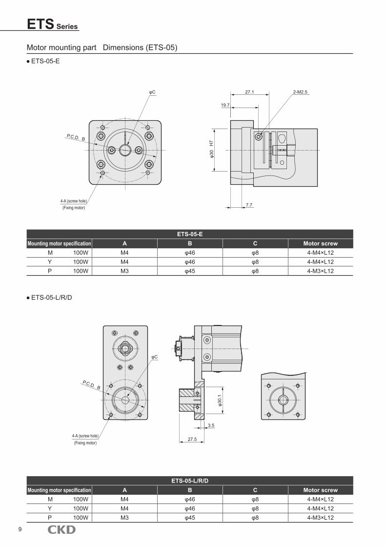
ETS Series
List of attachment products
Basic typeMotor mounting screw (motor mounting direction common)
Model No. Mounting motor Motor size Thread size Attached quantity
ETS-05ETS-06ETS-10ETS-12
M
100W
M4 2
Y M4 2
P M3 4
ETS-13ETS-14
M
200W400W
M5 4
Y M5 4
P M4 4
ETS-17
M
400W
M5 4
Y M5 4
P M4 4
M
750W
M6 4
Y M6 4
P M5 4
ETS-22
M
750W
M6 4
Y M6 4
P M5 4
Motor mounting direction is differentModel No. Attachment product name Attached quantity
E (External direct installation)B (Built-in)
Coupling(assembly shipment)
1 pc.
R (Right-side up installation)L (Left-side up installation)D (Bottom-side up installation)
Pulley 1 pc.
Belt 1 programs
*1 When at time of home position, limit sensor selectionSensor installation direction Shipment style Quantity
Internal sensor Shipped assembled at fixed position.3 pc.*2
External sensor Shipped attached *3
*1 How home position sensor and limit sensor are shipped depends on inside/outside mounting.*2 If "without" is selected for either the home position sensor or limit sensor, the other will automatically become "without". Also, the center dog will become
"without" too.*3 Sensor mounting screws will be attached too.
41
Home position sensor, limit sensor
Performance
Maker Type
Outside installation sensor OMRON EE-SX672
Inside installation sensor OMRON EE-SX674
Brown 5 to 24VDCPink LBlue 0VBlack OUTPUT
Descriptions Specifications
Hysteresis 0.025mm or less
light wave ( peak emission range) GaAs red out LED (940nm)
Indicator light lighting when light enters (red) (Lighting when light shuts for A type and R type)
Power voltage 5 to 24VDC 10% ripple(p-p) less than 10%
Current consumption 35mA or less (NPN type)
Control outputNPN type: NPN open collector output 5 to 24VDC less than 100mA Current when off less than
0.5mA residual voltage less than 0.8V (load current less than 40mA)
Ambient illuminance acceptance surface luminance fluorescent: less than 1,000lx
Ambient temperature When operates: -25 to +55 When storages: -30 to +80 (No freezing)
Ambient humidity When operates: 5 to 85%RH When storages: 5 to 95%RH(No freezing)
Degree of protection IP50IEC60529 standards
Code length 1m (connector (EE-10101M) with code)
Output circuit Wiring diagram
Terminal arrangement
Main circuit
Load
Voltage output100mA or less
ICOUT
L
+
DC5 to 24VDC
Indicator light (red)
ETS Series
42
Safety precautionsAlways read this section before starting use.
When designing and manufacturing devices using electric actuator, the manufacturer has an obligation to manufacture a safe device, and to check that the safety of the device's mechanical mechanism and the system operated by the electrical control that controls the device is secured.It is important to select, use, handle, and maintain the product appropriately to ensure that the CKD product is used safely.Observe warnings and precautions to ensure device safety.Check that device safety is ensured, and manufacture a safe device.
1 This product is designed and manufactured as a general industrial machine part. It must be handled by an operator having sufficient knowledge and experience in handling.
2 Use within the product's specification range.This product must be used within its stated specifications. Do not attempt to modify or additionally machine the product.This product is intended for use as a general-purpose industrial device or part. It is not intended for use outdoors or for use under the following conditions or environment.(Note that this product can be used when CKD is consulted prior to use and the customer consents to CKD product specifications. The customer must provide safety measures to avoid risks in the event of problems.)
Use for special applications including nuclear energy, railway, aircraft, marine vessel, vehicle, medical equipment, equipment, or applications coming into contact with beverage or food, amusement equipment, emergency shutoff circuits, press machine, brake circuits, or for safeguard.
Use for applications where life or assets could be adversely affected, and special safety measures are required.
3 Observe corporate standards and regulations, etc., related to the safety of device design.
4 Do not remove devices until safety is confirmed. Inspect and service the machine and devices after securing the safety of all the systems related to this product. Exercise caution as high temperature and charged parts can be present even when operation is stopped. Before starting device inspection or maintenance, turn off device power and other power to related devices. During the maintenance, please be careful for electric shock.
5 Observe warnings and cautions in the instruction manual of each product. Unexpected movement may occur during teaching operation or test operation, so keep hands, etc., away from the actuator. When conducting operation with the shaft not visible, be sure before starting operation that safety is ensured even if the actuator moves.
6 To prevent electric shock, observe warnings and cautions. Do not touch the heat sink, cement resistor and motor installed in the controller. Failure to do so may cause burn because these parts are hot. Take sufficient time before conducting inspection and other operations. Even immediately after the power is turned off, a high voltage is applied until the electric charge accumulated in the internal capacitor is discharged. Wait three minutes or so after turning the power off before touching these parts. Turn off the controller power source before conducting maintenance or inspection. Electric shocks from high voltage may occur. Do not connect or disconnect connectors while power is on. Misoperation, faults, or electrical shock may occur.
WARNING
The safety cautions are ranked as "DANGER", "WARNING" and "CAUTION" in this section.
DANGER: When a dangerous situation may occur if handling is mistaken leading to fatal or serious injuries, or when there is a high degree of emergency to a warning.
WARNING: When a dangerous situation may occur if handling is mistaken leading to fatal or serious injuries.
CAUTION: When a dangerous situation may occur if handling is mistaken leading to minor injuries or physical damage.
Note that some items described as "CAUTION" may lead to serious results depending on the situation.In any case, important information that must be observed is explained.
7 Set up the overcurrent protection device.In carrying out wiring to the controller, install over-current protective devices (such as wiring breaker and circuit protector) to the primary power supply for power (terminal block number L1, L2 and L3) and control (connector number CN3-24VDC) in accordance with "JIS B 9960-1:2008 Safety of machinery - Electrical equipment of machines - Part 1: General requirements".
(Excerpt from JIS B9960-1 7.2.1 General Requirements)Overcurrent protection shall be provided where the current in a machine circuit can exceed either the rating of any component or the allow-able current-carrying capacity of the conductors, whichever is the lesser value. The ratings or settings to be selected are specified in 7.2.10.
8 Observe the following cautions to prevent accidents.
43
Notes for ordering
1 Warranty period"Warranty Period" of this product is one (1) year from the first delivery to the place you specified.
2 Scope of warrantyIn case of a fault which is proved to be the responsibility of the CKD during the above warranty period, we shall offer a replacement part or a spare part of this product free of charge or repair the part in our plant free of charge.Note that the following faults are excluded from the warranty:
Operation under the conditions or in the environment derailing from those specified in the product specifications. Failure caused by lack of attention or erroneous control. Failure caused by other than the delivered product. Failure caused by operation derailing from the purposes for which the product is designed. Failure caused by modification in the structure, performance, specification or other features made by other than us after delivery, or failure caused by repairs done by other than our designated contractor. Loss in our product assembled to your machine or equipment, which would be avoided if your machine or equip-ment were provided with general functions, structures or other features common in the industry. Failure caused by reason that is unforeseeable with technology put into practical use at the time of delivery. Failure caused by fire, earthquake, flood, lightning, or other acts of God, earth shock, pollution, salt hazard, gas intoxication, excessive voltage, or other external causes.
The warranty mentioned here covers the discrete delivered product. Only the scope of warranty shall not cover losses induced by the failure of the delivered product.
3 Warranty for exported products(1) Products returned to the CKD factory or to a company or factory designated by CKD shall be repaired. Work and
cost necessary for transportation shall not be compensated for.(2) The repaired product shall be returned to a designated place in Japan with domestic packaging specifications.
This warranty specifies basic conditions. If warranty details in individual specification drawings or specifications differ from these warranty conditions, specification drawings or specifications shall take priority.
4 Compatibility confirmationIn no event shall CKD be liable for merchantability or fitness for a particular purpose, notwithstanding any disclosure to CKD of the use to which the product is to be put.
5 Scope of serviceTechnician dispatch service expense is not included in the price of delivered products. We shall receive the expense separately in the following cases:(1) Installation adjustment instruction and presence in test operation(2) Maintenance, adjustment and repair(3) Technical guidance and technical training (operation, program, wiring method, safety education, etc.)
44
Safety precautionsAlways read this section before starting use.
Design & Selection
Danger Do not operate the product in flammable or explo-sive atmospheres. Doing so may create the risk of ignition and explosion.
Keep the actuator away from drops of water or oil. Failure to do so may result in a fire or faulty operation.
Make sure to hold and lock (including work pieces) when installing the product. The operator could be injured due to falling or abnormal operation of the product.
Warning Use the product within the product-specific specification range.
Install a protection cover in case of possible danger to the operator.
If the electric actuator's movable parts may pose danger to the operator, be sure that the actuator has a structure preventing the operator from entering its operation range or touching the movable parts directly.
Do not get close to the robot if you wear a medical device such as a pacemaker. Strong magnets used in the robot may cause misoperation of the pacemaker and other devices.
Take the operation status during emergency stop into consideration.
In case the safety device stops the machine due to emergency stop, power outage or other system errors, the electric actuator must be designed so that its movement causes no damage to the operator and equipment.
Install the actuator inside and keep away from humid places.Electrical leakage or fire may occur in places where rainwater drips or is humid (under the conditions its humidity is more than 85% and condensation occurs). Drop of oil and oil mist should also be prohibited.
Failure to do so may result in damage or faulty operation.
Use and store the product under the correct use/storage temperature in atmospheres without condensation. (storage ambient temperature: -10°C to 50°C, storage ambient humidity: 35% to 80%, operating ambient temperature: 0°C to 40°C, operating ambient humidity: 35% to 80%)Failure to do so may result in shorter life or abnormal stop of the actuator. Please ventilate if the heat is confined.
To prevent failure, explosion, or ignition, install the product away from direct sun, dust, flammable items, corrosive gas, explosive gas, and flammable gas. Consideration has not been taken regarding chemical resistance for this product.Failure to do so may result in the cause of break, explosion or ignition. Do not use and store the actuator in places with strong electromagnetic waves, ultraviolet rays and radiation.Doing so may cause malfunction or failure.
Take possibility of power source failure into consideration.
In case of a failure in the power source, take countermeasures without causing trouble or damage to the operator or equipment.
Consider the operation status if the machine is reactivated after emergency stop or abnormal stop.
The machine must be designed so that reactivation causes no damage to the operator or equipment.
If the electric actuator must be reset to the start position, be sure to provide the machine with a safe control device.
Consider the possibility of the failure of the mounted motor. Take preventive measures not to damage human bodies and
equipments, in case of failure of the power source.
Do not use the actuator under shock or vibration conditions.
Do not apply load exceeding the allowance specified in the selection document to the actuator.
Caution Do not hit the trolley table against the stroke end.
Specify the maintenance conditions in the equipment instruction manual.
Product functions may be deteriorated significantly due to usage, service conditions or maintenance. This may result in failure to ensure safety. Conducting maintenance with accuracy allows the product to fully exert its functions.
Read through the instruction manual to perform installation and adjustment properly. The product is manufactured in conformity with the related standards. Never attempt to modify the product.
Read user instructions for motor and control attached to the product. Then wire/design with attention paid to safety.
The suitability of our products with systems, machines, equipment that you are going to use with must be checked and determined at your own risk.
Individual precautions : Electric driven actuator ETS Series
45
Installation & Adjustment
Danger Do not enter the operating range of the actuator when the product is ready to operate. The product may move suddenly and injure.
Warning Overturn, vibration, and shock should be avoided during transportation due to the integrated precision components. Parts could damage.
In case of locating temporarily, place the actuator in a horizontal position. Do not climb on top of the package, or place any object. Set ambient temperature -10° to 50° and ambient humidity 35 to 80% when transporting without condensation or freezing. If not, failure may occur.
Attachment to incombustible items is necessary. Direct attachment to flammable items or near the items could cause a fire.There is a risk of burns.
Do not climb on top of the product, use it as a footstool or, place any object.That could be the causes of accidents by falling, turnover of the product, injury from falling, damage to the product, or operation errors caused by the damage.
Even if there is a power failure, take countermeasures so as to cause no damage to human body, or to machines.Unexpected accident may happen.
If any abnormality is found, stop using immediately and contact our sales office nearest you.
Do not operate the moving part of the product or decelerate rapidly by an external force. There is a possibility to damage or malfunction by the regenerative current.
During home return, do not hit the mechanical stopper etc. other than the pressing operation.Damaged feed screw may cause malfunction.
Durability can be changed by transport load or environment. Sufficient setting for transport load etc. is required. In addition, use without shock applying to the moving part. Do not operate on the slider and give it an excessive moment.The product can be damaged or malfunction.
Flatness of the mounting surface should be 0.05 mm / 200 mm or less. Do not give twist or bending force to the product.
Flatness of the side of a work piece attaching to the slider should be less than 0.02mm. Do not give twist or bending force to it. The product can be damaged or malfunction. For tightening screws to mount the body, apply an appropriate torque described in table below.
Thread size Tightening torque (N m)M3 0.7
M4 1.5
M5 3
M6 5.2
M8 12.5
M10 24.5
During Use & Maintenance
Danger Working with wet hands may cause an electric shock.
Caution Conduct a regular check 2 to 3 times in a year to make sure to work properly.
Grease lubrication interval is usually 100km. However, it varies depending on the use conditions. It is
recommended to determine the lubrication interval by the initial inspection. See the instruction manual for details.
When performing maintenance, inspection, repair, stop the power supply to the product before. Call attention to the others around you not to turn the power on, or operate carelessly by a third party.
In case of disposing the product, follow the law of waste disposal and public cleaning outsource to professional waste disposal service.
ETS Series
Caution Installing the actuator in places under large vibration or impact conditions may lead to malfunction.Malfunction could occur.
46
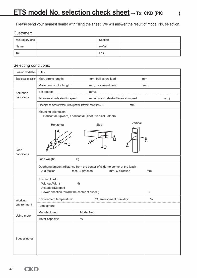
Desired model No. ETS-
Basic specification Max. stroke length: mm, ball screw lead: mm
Actuation conditions
Movement stroke length: mm, movement time: sec.
Set speed: mm/s
Set acceleration/deceleration speed: mm/s2 (set acceleration/deceleration speed: sec.)
Precision of measurement in the partial different conditions: ± mm
● Dust generation is minimized with a full cover structure and suction port, based on the ETS series.
● Motor size: 7 types, Lead: 7 types, Motor mounting direction: 5 types
● Mount a motor you're familiar with● Mounting specifications of the home position sensor and
limit sensor can be selected● Stroke can be selected from 100 to 1500 mm (50 mm
pitch)● Supports a wide range of usage with maximum load
capacity of 150 kg and maximum speed of 2000 mm/s
■ Belt drive (ECV Series)● Dust generation is minimized with a full cover structure
and suction port, based on the ETV series.● Motor size: 6 types, Motor mounting direction: 6 types● Mount a motor you're familiar with
Catalog No. CC-1216A, CC-1217A, CC-1257A
ETS Series
48
Direct actuator compact type AX6000M Series
Space savingIn addition to industry min. external dimensions, for the concentric shape (the fixed axis and the rotation axis is the same), compact machine design that saves a waste of space is possible.
FlexibleOperation can be realized as imagined because it has abundant program creation functions.Furthermore, it corresponds to simple operation setting such as automatic creation point specified program.
High reliable and maintenance freeBecause of the direct-drive system(gearless), there is no need to worry about gear damage or accuracy changes through wear of the gear unit.
Electric actuator ERL2/ESD2 Series
Positioning point numberAdded "63 points positioning", which has broader utilities to usual "7 points positioning"
Easy setting toolAs well as teaching pendant (ETP2), added easy computer setting software (E-Tools)
Perfect compatibility"Perfect compatibility" which allows all combinations between actuators and controllers
ETS Series
Catalog No. CC-1219A
Absodex High Precision Type AX7000X Series
■ High resolutionEquipped with a high resolution encoder (4, 194, 304 pulses/rotation) with resolution approximately 8 times that of conventional models. Repeatability of ±2 sec is achieved.
■ High responsivityResponsivity and stability at a constant speed are greatly improved, as well as high-precision positioning accuracy.
■ Flexible positioning possibleEquipped with a "flexible programming function" to easily realize complex actions and the "industry's largest number of I/O signals" useful for communication with higher-level devices.
■ PC software AX Tools, easier to useEquipped with the industry's first AI (Artificial Intelligence) adjustment function.Even a beginner can make adjustments like an expert, allowing faster system setup.
Catalog No. CC-1238A
Catalog No. CC-1148A
Recipient of 11th Cho Monodzukuri Innovative Parts and Components Incentive Award
49
Direct actuator quick response typeAX1000T, AX2000T, AX4000T Series
Ample actuators12 types of actuator are available, from 6 - 1000 N m.
5 types of interface options5 types of interface for driver are available; parallel I/O, (NPN, PNP), CC-Link, DeviceNet, PROFIBUS-DP.
Electric actuator KBZ Series
High tact timeMax. operation speed of 800mm/s possible
Servo motorServo motor for a compact axis. Allow to high-speed operation, quick acceleration and deceleration, and high load capacity.
Absolute specificationsNo need for return-home routine.
Compact controllerDrastic downsizing.
Electric actuator ESSD/ELCR Series
Space savingWiring and installation space for the controller is no longer required.
Design pneumaticallyShaped, used, operated like pneumatic cylinder.
Flexible motion controlThree control modes (solenoid valve mode,7 position mode and pitch feeding mode)available.
Easy teachingEasy setting with 5 buttons. Direct configuration is available.
●Specifications are subject to change without notice.
The goods and their replicas, or the technology and software in this catalog are subject to complementary export regulations by Foreign Exchange and Foreign Trade Law of Japan.If the goods and their replicas, or the technology and software in this catalog are to be exported, laws require the exporter to make sure they will never be used for the development or the manufacture of weapons for mass destruction.
2016.7CKD Corporation 2016 All copy rights reserved.
Website http://www.ckd.co.jp/
U.S.A.CKD USA CORPORATION●CHICAGO HEADQUARTERS
4080 Winnetka Avenue, Rolling Meadows, IL 60008, USAPHONE +1-847-368-0539 FAX +1-847-788-0575
・CINCINNATI OFFICE・SAN ANTONIO OFFICE・SAN JOSE OFFICE・DETROIT OFFICE
MexicoCKD MEXICO, S. DE R.L. DE C.V.
Cerrada la Noria No. 200 Int. A-01, Querétaro Park II, Parque Industrial Querétaro, Santa Rosa Jáuregui, Querétaro, C.P. 76220, MéxicoPHONE +52-442-161-0624
EuropeCKD CORPORATION EUROPE BRANCH
De Fruittuinen 28 Hoofddorp, the NetherlandsPHONE +31-(0)23-5541490 FAX +31-(0)23-5541491
・CZECH OFFICE・UK OFFICE・FRANKFURT OFFICE
MalaysiaM-CKD PRECISION SDN.BHD.●HEAD OFFICE
Lot No.6,Jalan Modal 23/2, Seksyen 23, Kawasan MIEL,Fasa 8, 40300 Shah Alam,Selangor Darul Ehsan, MalaysiaPHONE +60-(0)3-5541-1468 FAX +60-(0)3-5541-1533