49
Motors and Control Jizhong Xiao Department of Electrical Engineering City College of New York [email protected] Capstone Design -- Robotics
| Date post: | 19-Dec-2015 |
| Category: |
Documents |
| View: | 219 times |
| Download: | 1 times |
Motors and Control
Jizhong Xiao
Department of Electrical Engineering
City College of New York
Capstone Design -- Robotics
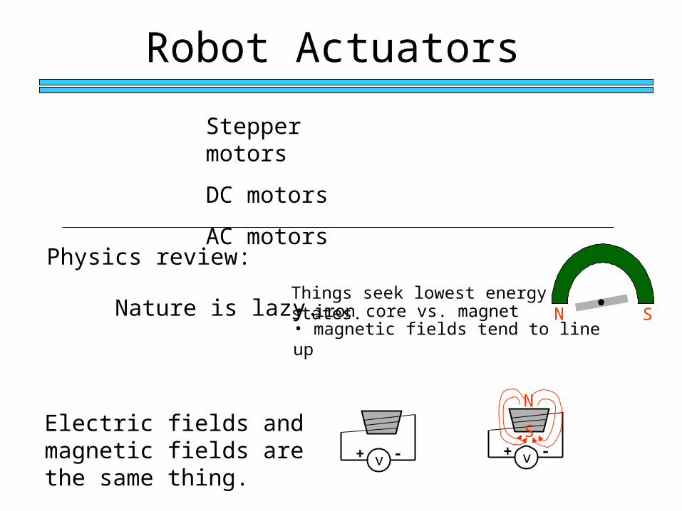
Robot Actuators
Stepper motors
DC motors
AC motors
Physics review:
Electric fields and magnetic fields are the same thing.
Nature is lazy.Things seek lowest energy states.• iron core vs. magnet• magnetic fields tend to line up
v+ - v+ -
N
S
N S
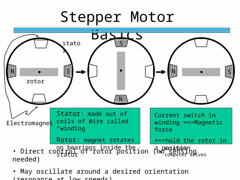
Stepper Motor Basics
S
N
Stator: made out of coils of wire called “winding”
Rotor: magnet rotates on bearings inside the stator
• Direct control of rotor position (no sensing needed)
• May oscillate around a desired orientation (resonance at low speeds)
• Low resolution
printerscomputer drives
SN
Electromagnet
stator
rotor
N S
Current switch in winding ==>Magnetic force
==>hold the rotor in a position
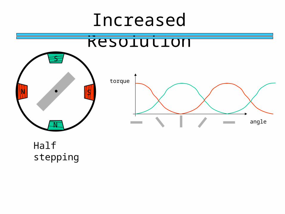
Increased Resolution
Half stepping
S
S
N
N
angle
torque
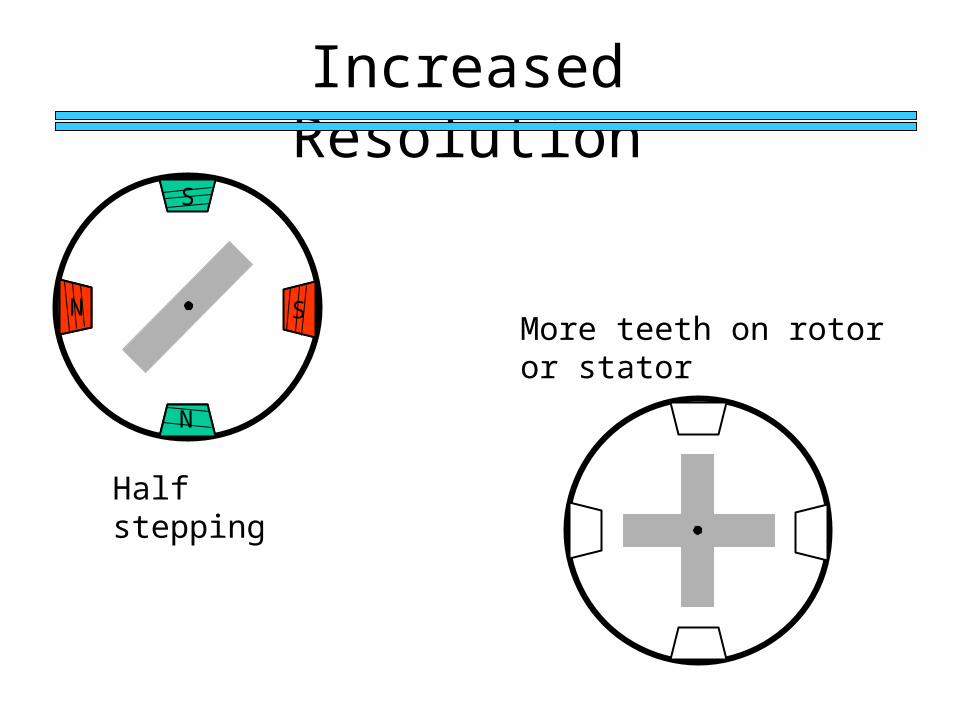
Increased Resolution
More teeth on rotor or stator
Half stepping
S
S
N
N
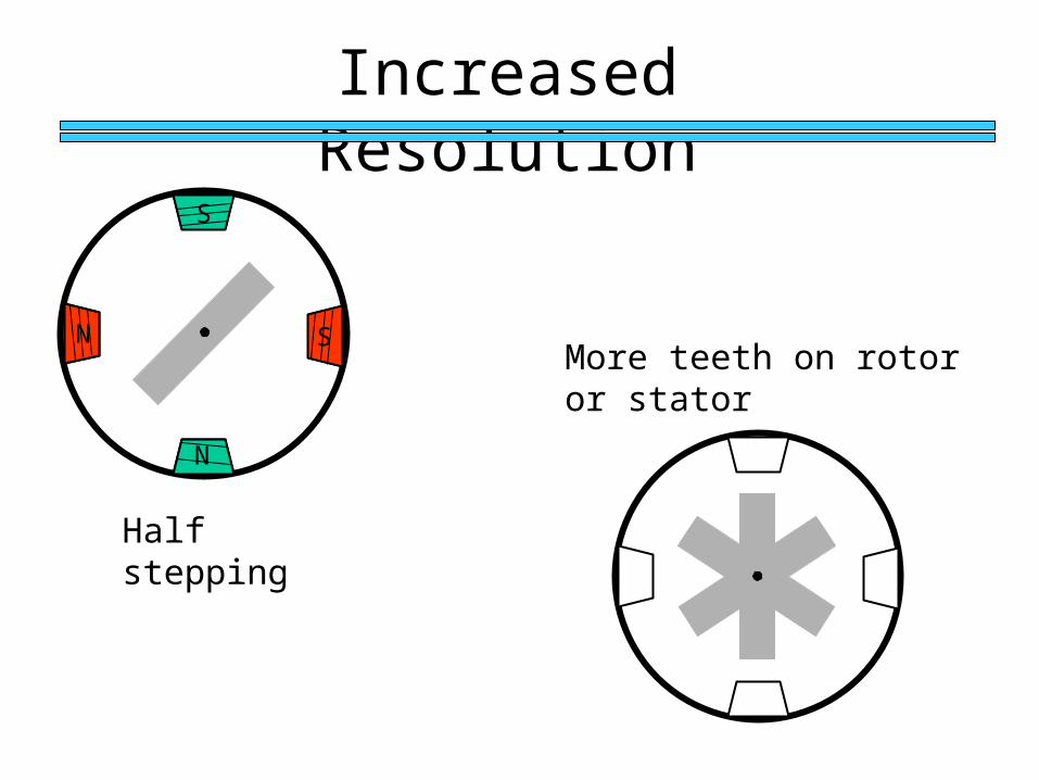
Increased Resolution
More teeth on rotor or stator
Half stepping
S
S
N
N
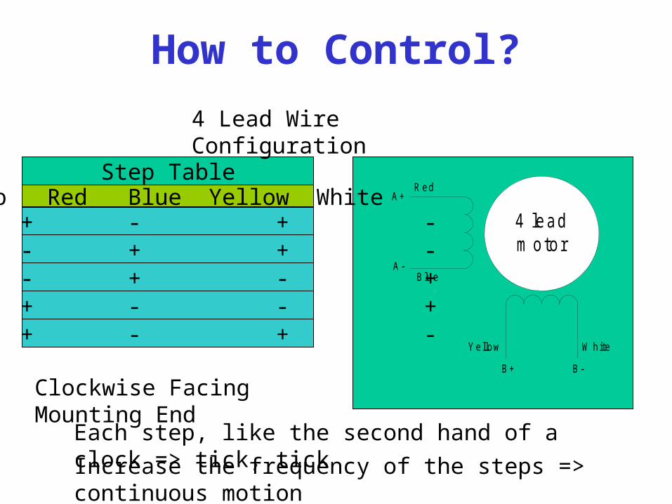
How to Control?
Step TableStep Red Blue Yellow White
0 + - + -1 - + + -2 - + - +3 + - - +4 + - + -
4 leadm otor
Red
B lue
A+
A-
B+ B-
Yellow W hite
4 Lead Wire Configuration
Clockwise Facing Mounting End
Increase the frequency of the steps => continuous motion
Each step, like the second hand of a clock => tick, tick
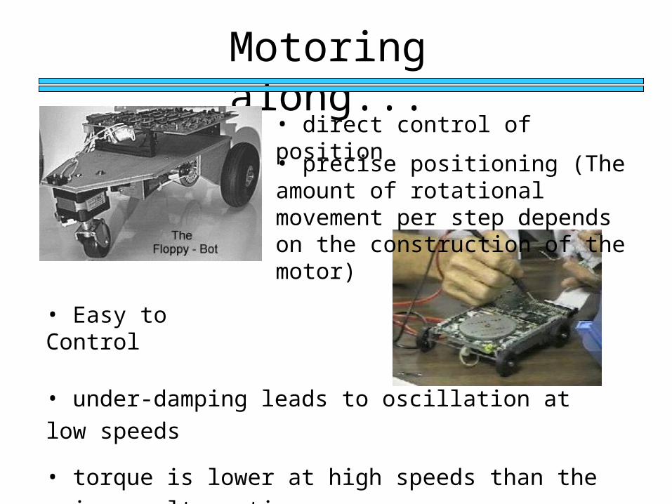
Motoring along...
• direct control of position
• precise positioning (The amount of rotational movement per step depends on the construction of the motor)
• Easy to Control
• under-damping leads to oscillation at low speeds
• torque is lower at high speeds than the primary alternative…
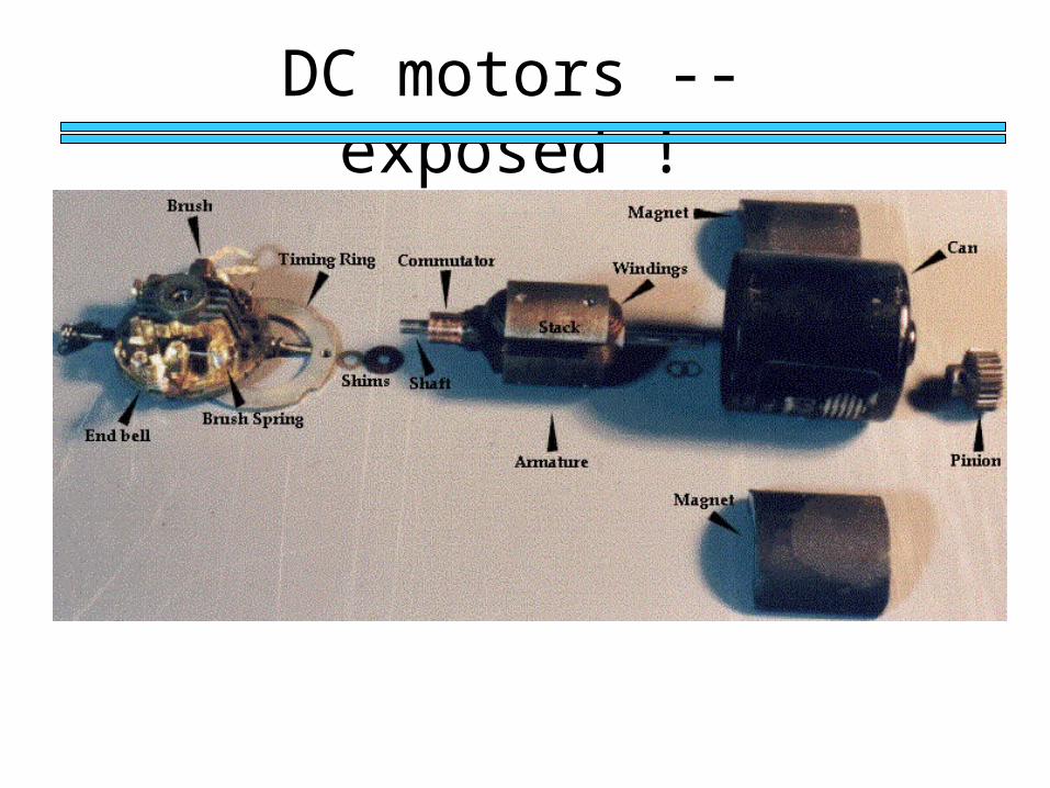
DC motors -- exposed !
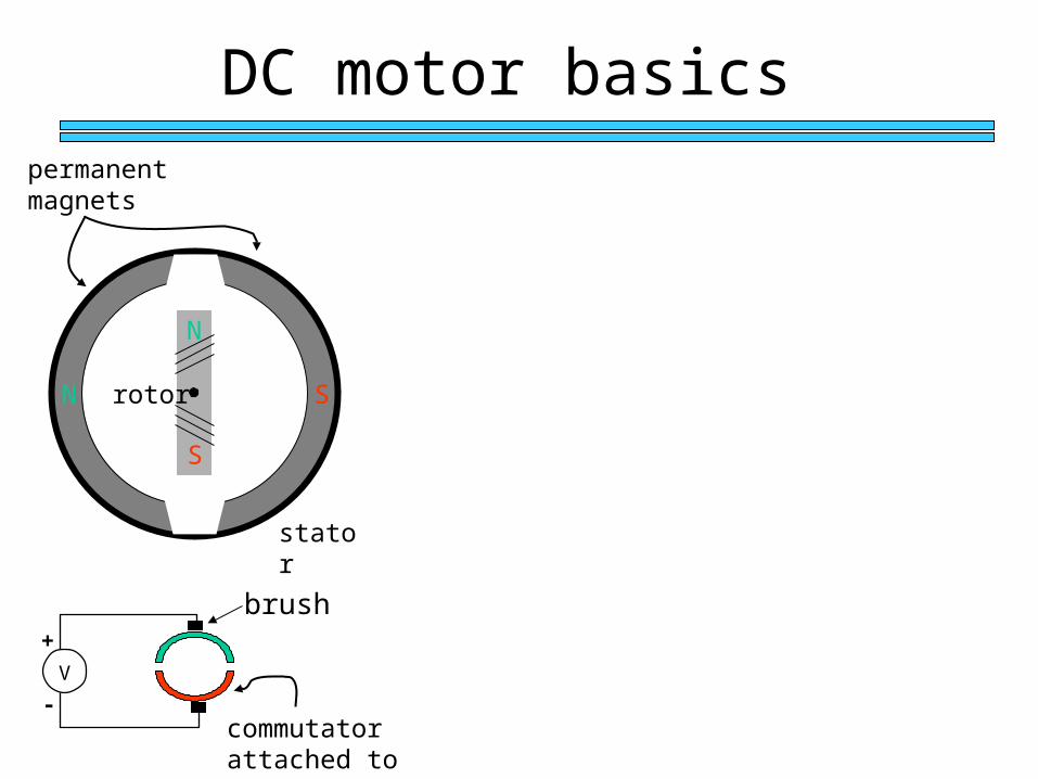
DC motor basics
N
S
N S
stator
rotor
permanent magnets
commutator attached to shaft
V
+
-
brush
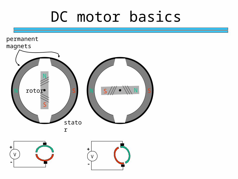
DC motor basics
N
S
N S
stator
rotor
permanent magnets
N SS N
V
+
-V
+
-
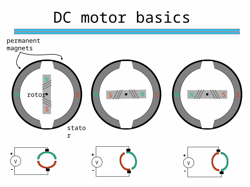
DC motor basics
N
S
N S
stator
rotor
permanent magnets
N SS N N SN S
V
+
-V
+
-
V
+
-
Position Sensors
Optical Encoders Relative position Absolute position
Other Sensors Resolver Potentiometer
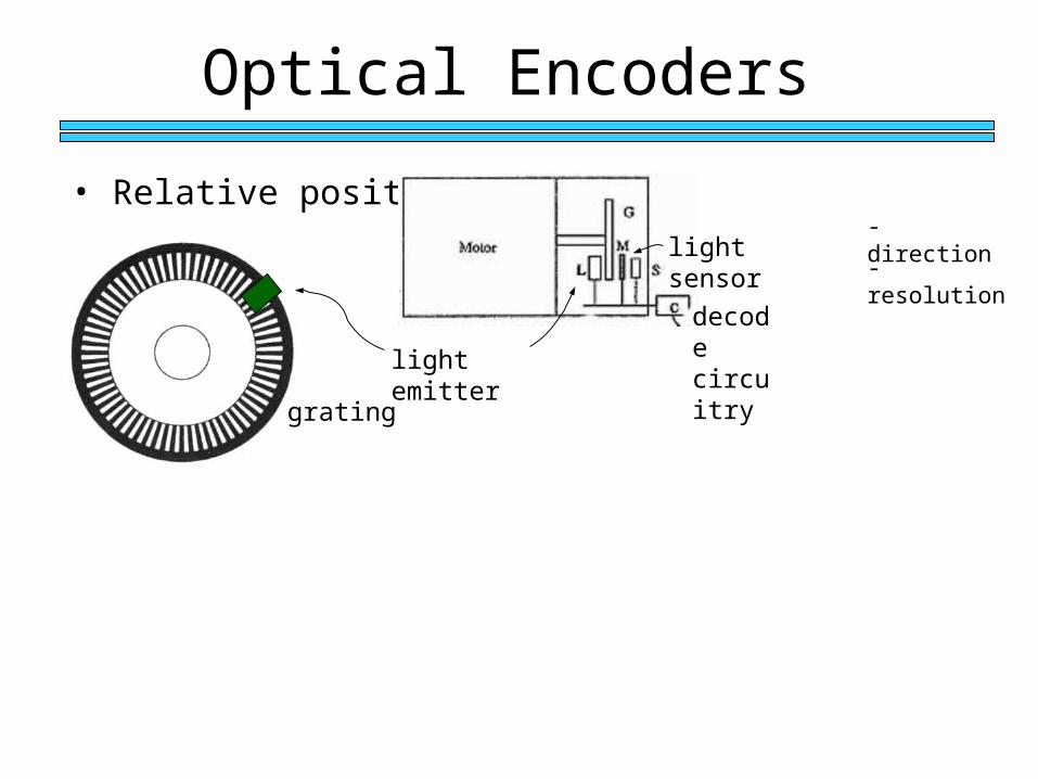
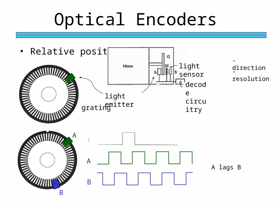
Optical Encoders
• Relative position - direction
- resolution
grating
light emitter
light sensor
decode circuitry
Ideal
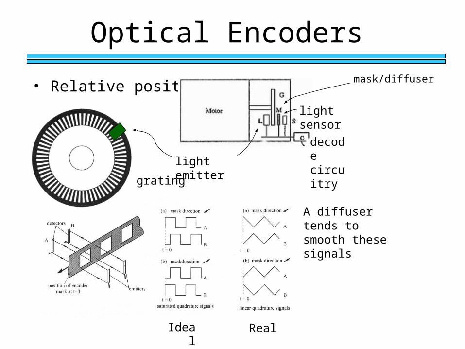
Optical Encoders
• Relative position mask/diffuser
grating
light emitter
light sensor
decode circuitry
Real
A diffuser tends to smooth these signals
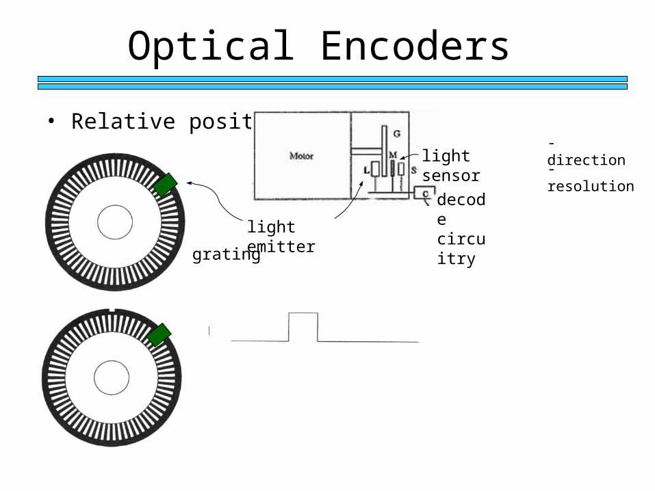
Optical Encoders
• Relative position - direction
- resolution
grating
light emitter
light sensor
decode circuitry
Optical Encoders
• Relative position - direction
- resolution
grating
light emitter
light sensor
decode circuitry
A
B
A
B
A lags B
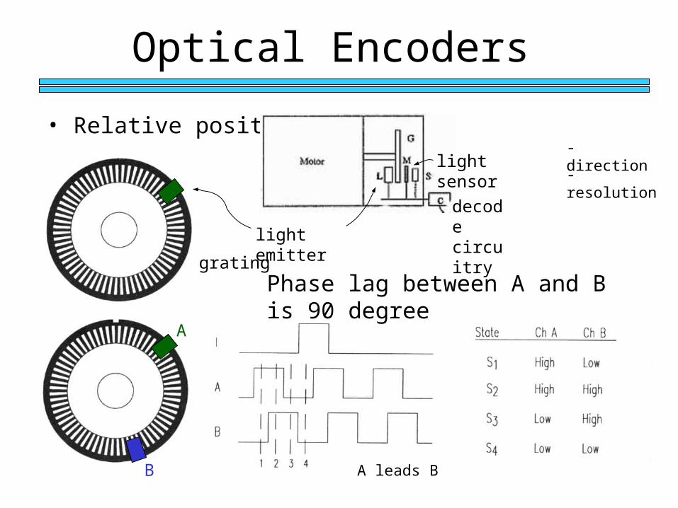
Optical Encoders
• Relative position - direction
- resolution
grating
light emitter
light sensor
decode circuitry
A
B A leads B
Phase lag between A and B is 90 degree
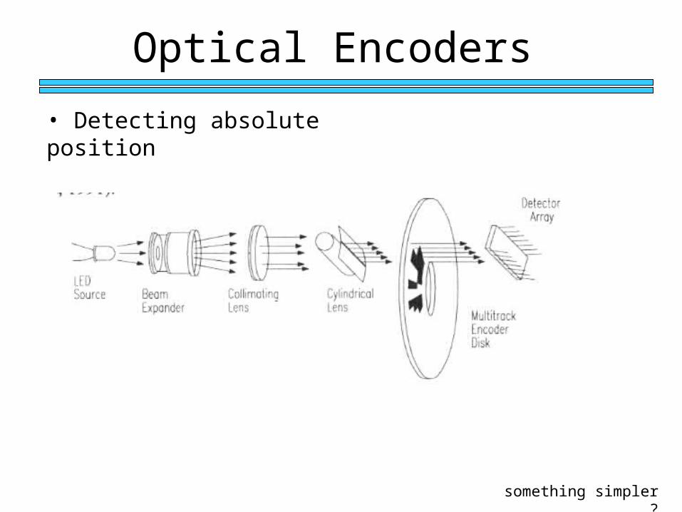
Optical Encoders
• Detecting absolute position
something simpler ?
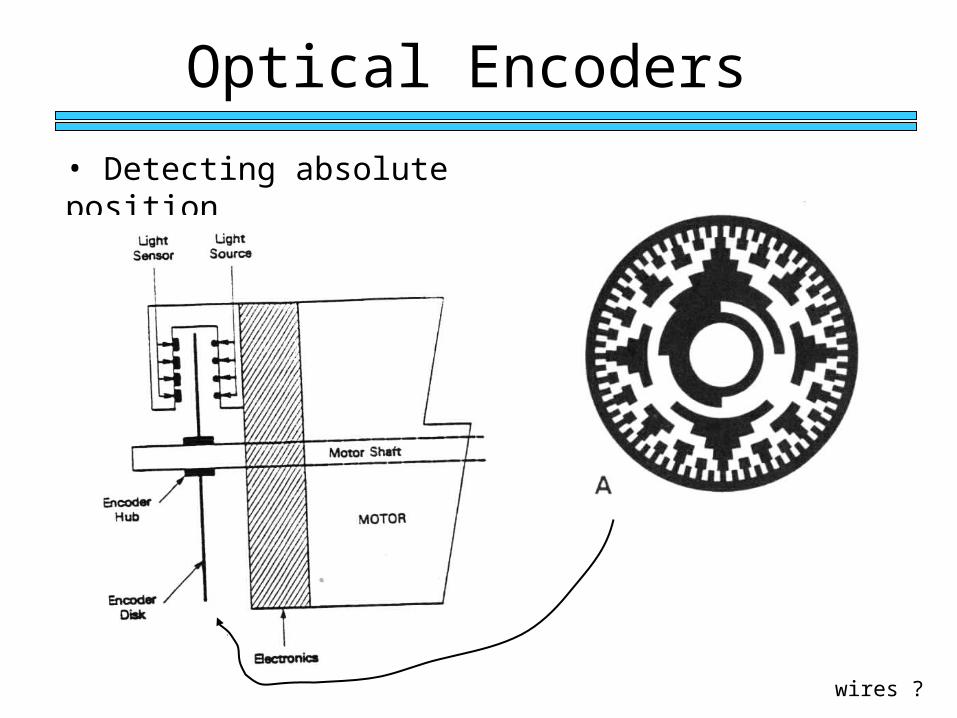
Optical Encoders
• Detecting absolute position
wires ?
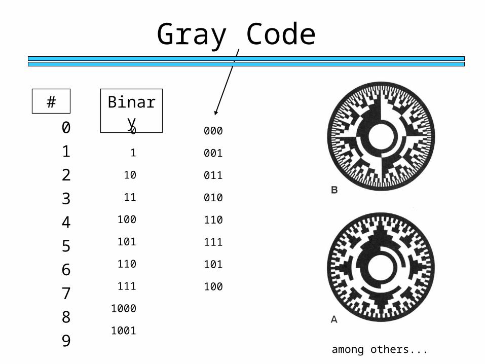
Gray Code
0
1
2
3
4
5
6
7
8
9
# Binary
0
1
10
11
100
101
110
111
1000
1001
000
001
011
010
110
111
101
100
among others...
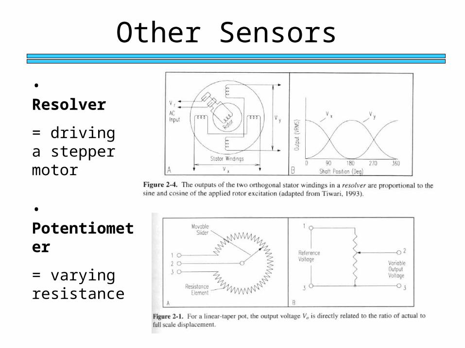
Other Sensors
• Resolver
= driving a stepper motor
• Potentiometer
= varying resistance
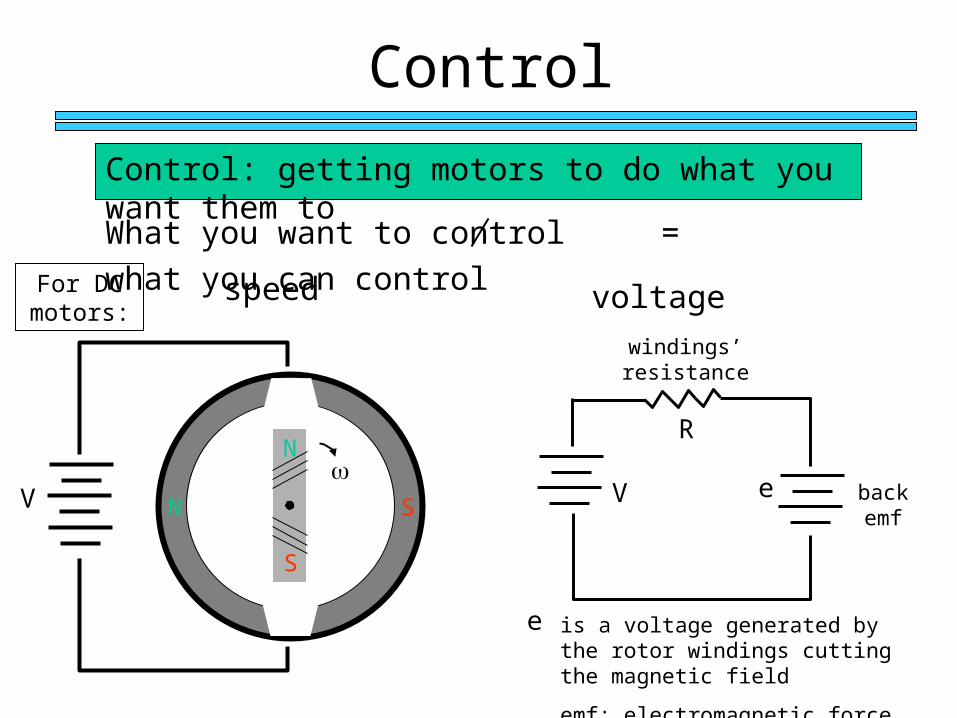
Control
What you want to control = what you can control
For DC motors:
speed voltage
N
S
N SV
V e back emf
R
windings’ resistance
e is a voltage generated by the rotor windings cutting the magnetic field
emf: electromagnetic force
Control: getting motors to do what you want them to
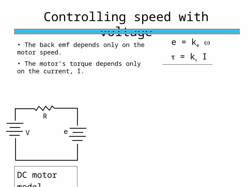
Controlling speed with voltage
DC motor model
V e
R
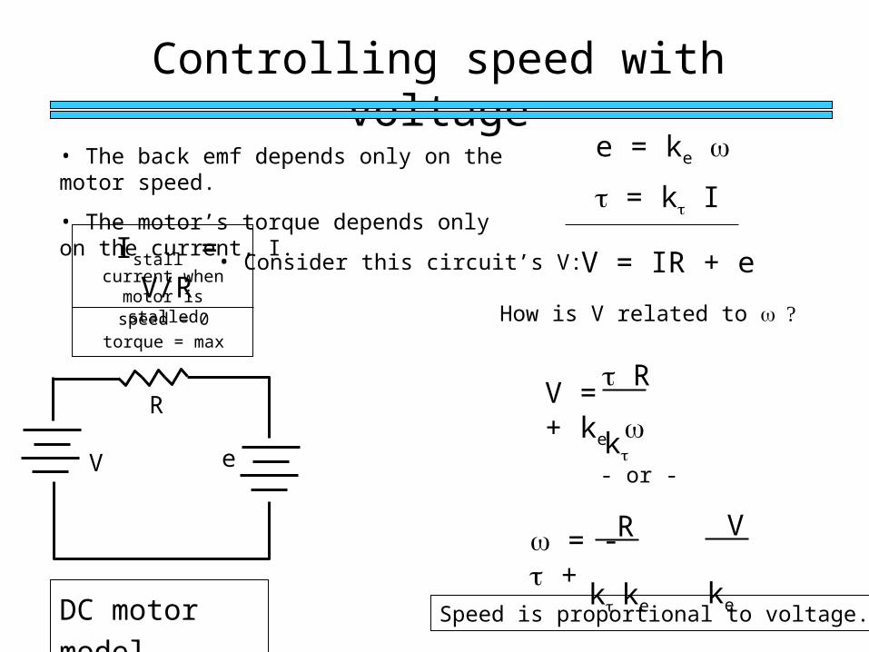
• The back emf depends only on the motor speed.
• The motor’s torque depends only on the current, I.
e = ke
= k I
kke
Controlling speed with voltage
DC motor model
V e
R
• The back emf depends only on the motor speed.
• The motor’s torque depends only on the current, I.
e = ke
= k I
• Consider this circuit’s V: V = IR + eIstall = V/Rcurrent when
motor is stalledspeed = 0
torque = max
How is V related to
V = + ke R k
- or -
= - + R ke V
Speed is proportional to voltage.
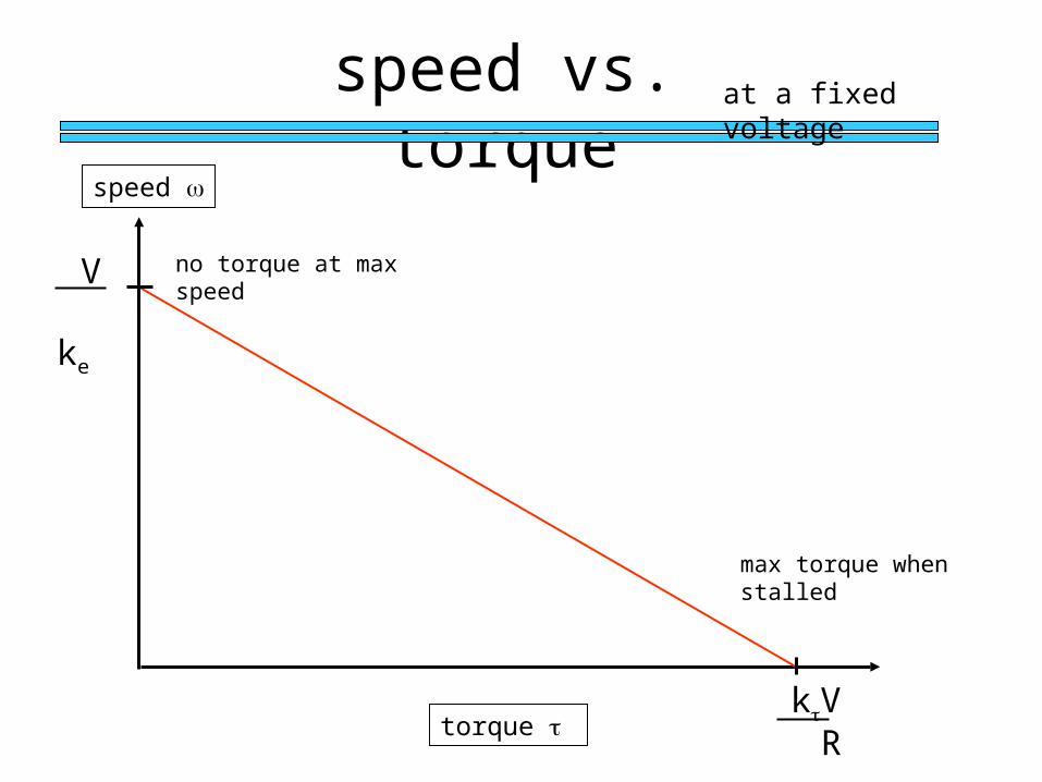
speed vs. torque
torque
speed
ke V
at a fixed voltage
R kV
max torque when stalled
no torque at max speed
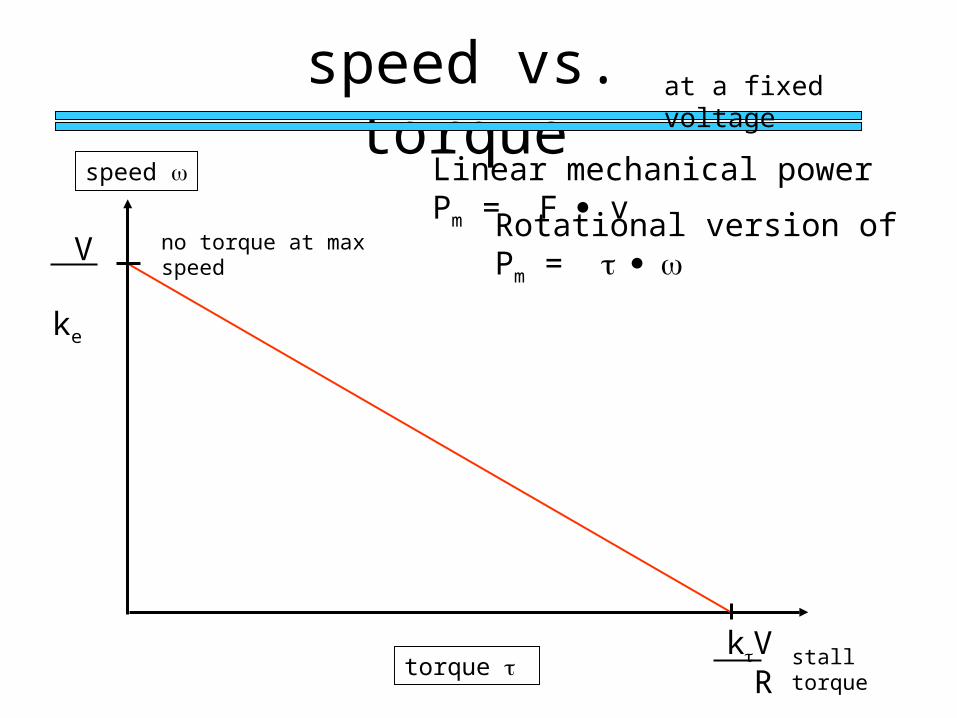
speed vs. torque
torque
speed
ke V
at a fixed voltage
R kV stall torque
no torque at max speed
Linear mechanical power Pm = F v
Rotational version of Pm =
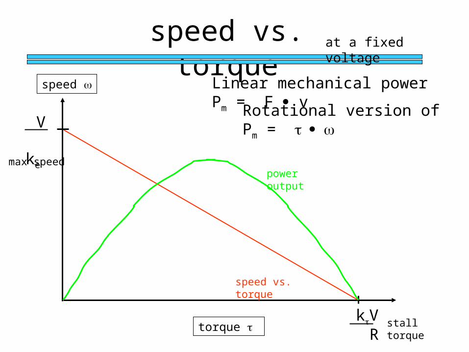
speed vs. torque
torque
speed
ke V
at a fixed voltage
R kV stall torque
max speed
Linear mechanical power Pm = F v
Rotational version of Pm =
power output
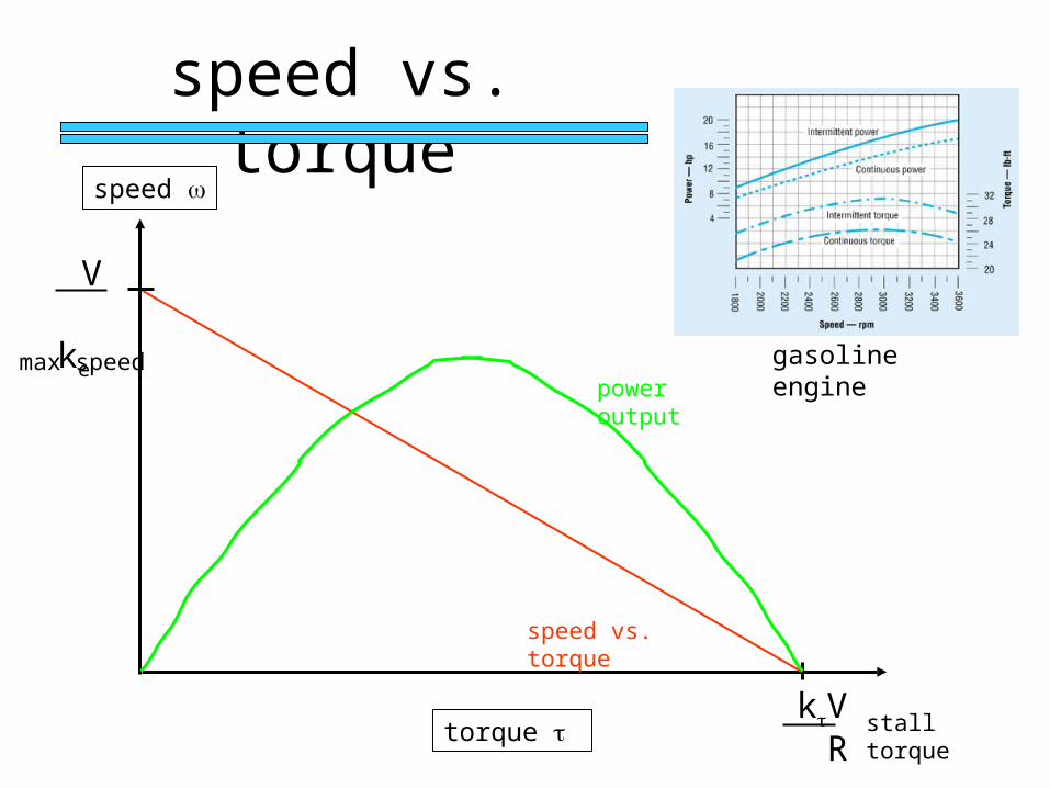
speed vs. torque
speed vs. torque
torque
speed
ke V
R kV
power output
speed vs. torque
gasoline enginemax speed
stall torque
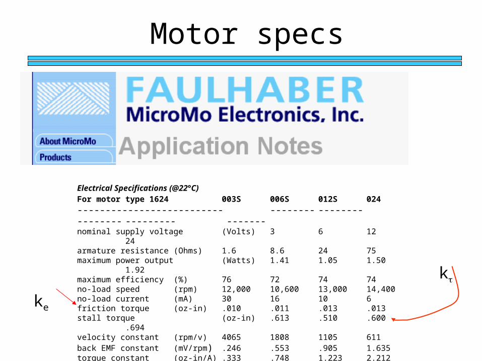
Motor specs
Electrical Specifications (@22°C)For motor type 1624 003S 006S 012S 024
-------------------------- -------- -------- -------- --------- -------nominal supply voltage (Volts) 3 6 12 24armature resistance (Ohms) 1.6 8.6 24 75maximum power output (Watts) 1.41 1.05 1.50 1.92maximum efficiency (%) 76 72 74 74no-load speed (rpm) 12,000 10,600 13,000 14,400no-load current (mA) 30 16 10 6friction torque (oz-in) .010 .011 .013 .013stall torque (oz-in) .613 .510 .600 .694velocity constant (rpm/v) 4065 1808 1105 611back EMF constant (mV/rpm) .246 .553 .905 1.635torque constant (oz-in/A) .333 .748 1.223 2.212armature inductance (mH) .085 .200 .750 3.00
ke
k
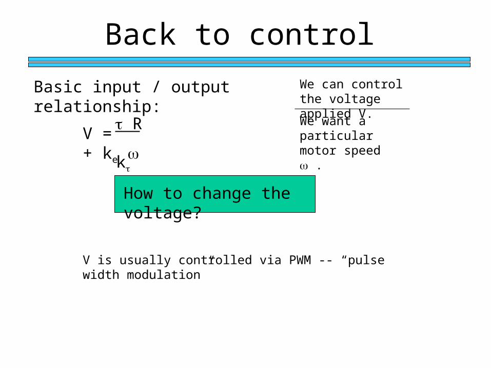
Back to control
Basic input / output relationship:
How to change the voltage?
We want a particular motor speed .
We can control the voltage applied V.
V = + ke R k
V is usually controlled via PWM -- “pulse width modulation”
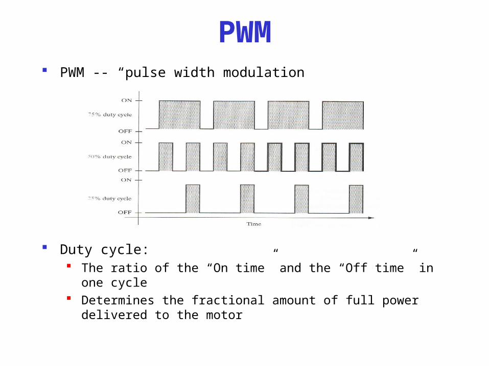
PWM PWM -- “pulse width modulation
Duty cycle: The ratio of the “On time” and the “Off time” in one cycle Determines the fractional amount of full power delivered to
the motor
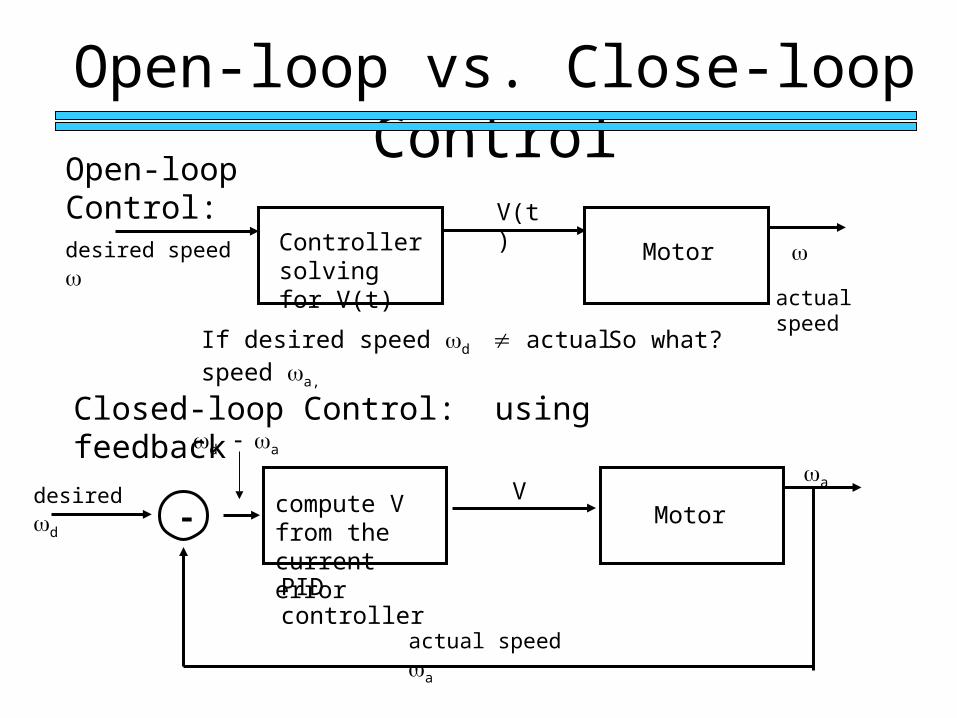
Open-loop vs. Close-loop Control
Open-loop Control:
actual speed
desired dV
Motor
a
actual speed a
- compute V from the current error
d a
Closed-loop Control: using feedback
desired speed Controller solving for V(t)
V(t)
Motor
If desired speed d actual speed a,
So what?
PID controller
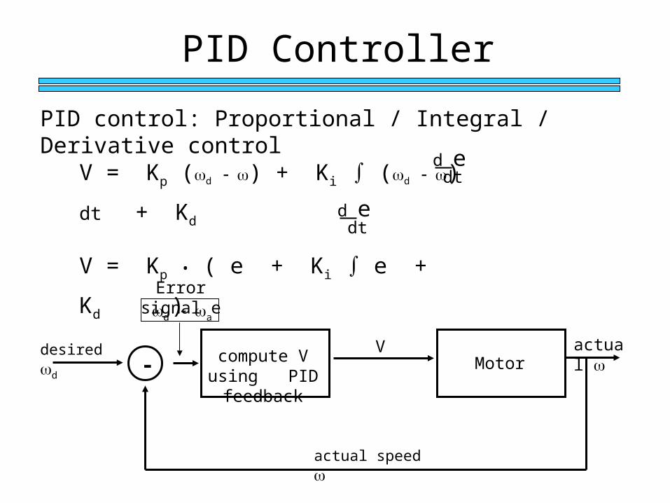
PID Controller
desired dV
Motoractual
actual speed
- compute V using PID feedback
d a
Error signal e
PID control: Proportional / Integral / Derivative control
V = Kp (d ) + Ki ∫ (d ) dt + Kd
V = Kp • ( e + Ki ∫ e + Kd )d e dt
d e dt
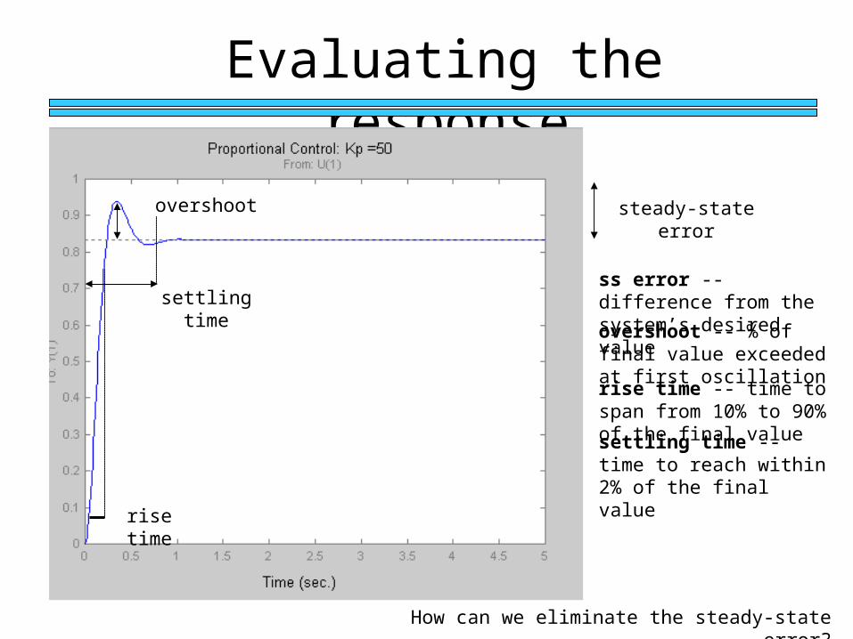
Evaluating the response
How can we eliminate the steady-state error?
steady-state error
settling time
rise time
overshoot
overshoot -- % of final value exceeded at first oscillation
rise time -- time to span from 10% to 90% of the final value
settling time -- time to reach within 2% of the final value
ss error -- difference from the system’s desired value
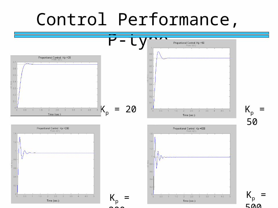
Control Performance, P-type
Kp = 20
Kp = 200
Kp = 50
Kp = 500
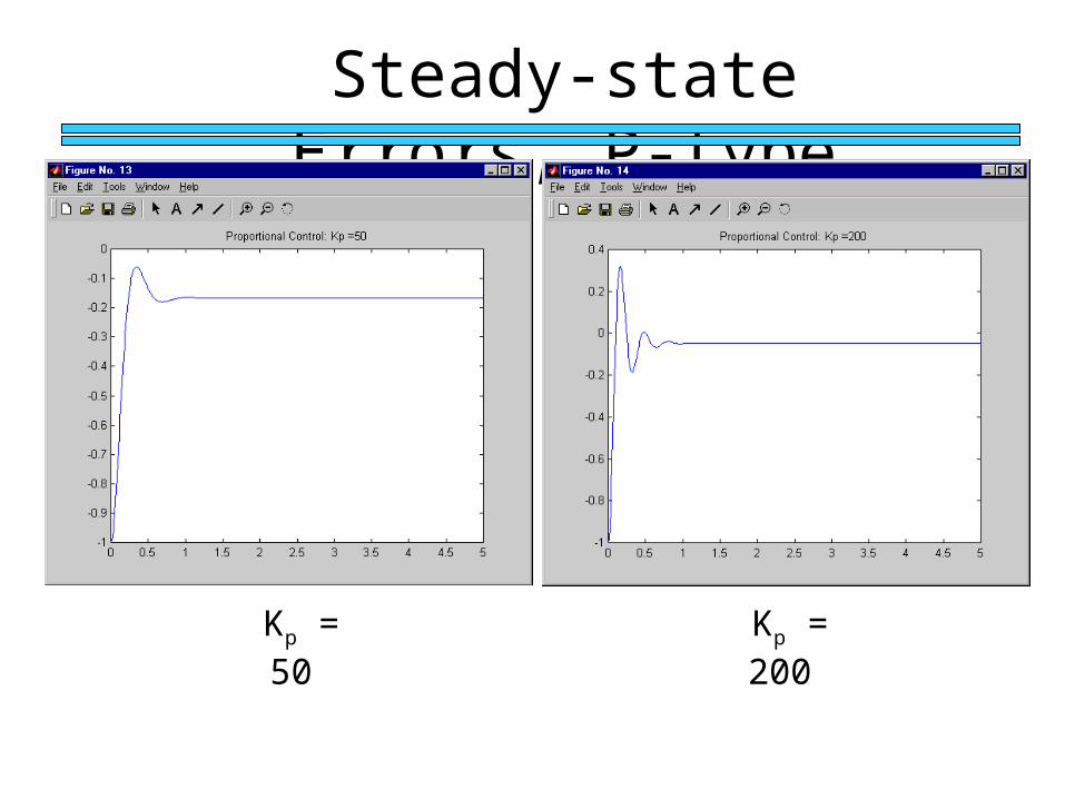
Steady-state Errors, P-type
Kp = 200 Kp = 50
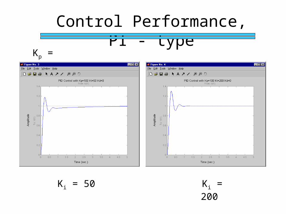
Control Performance, PI - type
Kp = 100
Ki = 50 Ki = 200
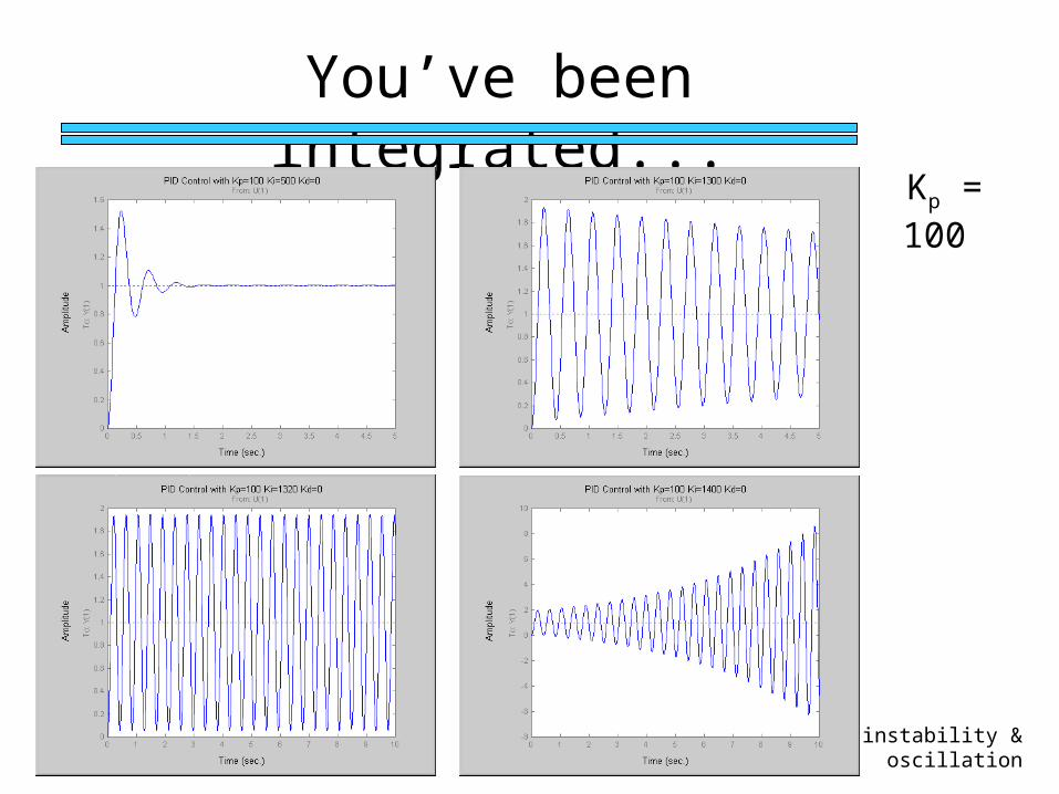
You’ve been integrated...
Kp = 100
instability & oscillation
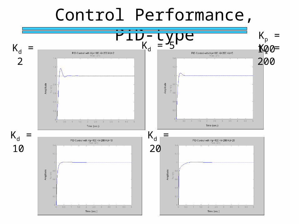
Control Performance, PID-typeKp = 100 Ki = 200 Kd = 2
Kd = 10 Kd = 20
Kd = 5
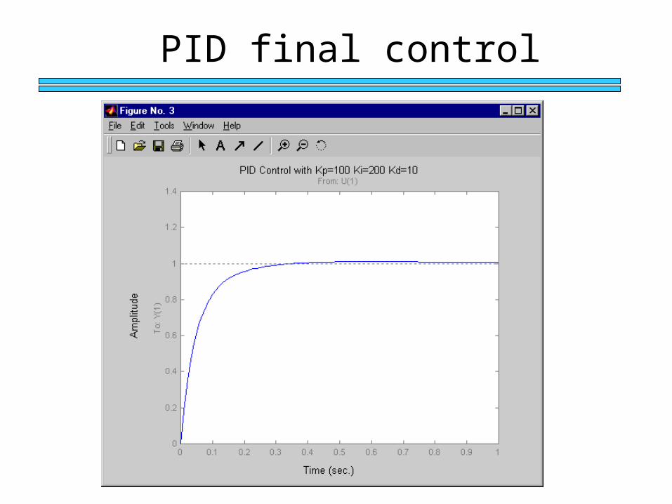
PID final control
PID Tuning
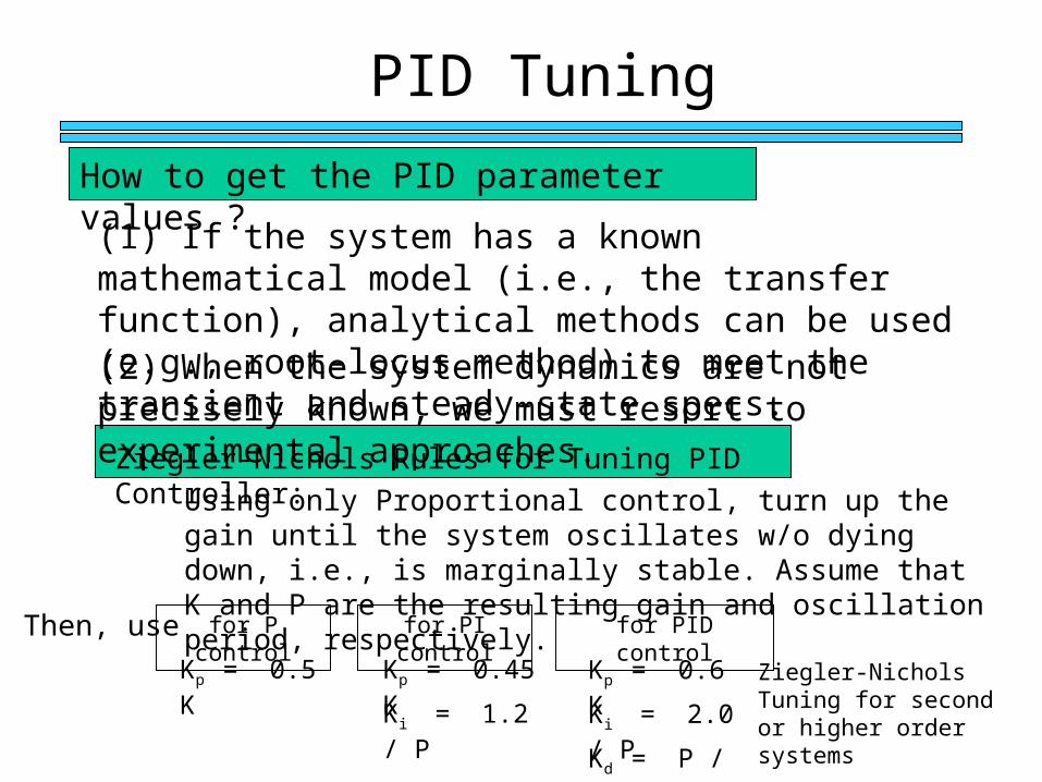
How to get the PID parameter values ?
(1) If the system has a known mathematical model (i.e., the transfer function), analytical methods can be used (e.g., root-locus method) to meet the transient and steady-state specs. (2) When the system dynamics are not precisely known, we must resort to experimental approaches.
Using only Proportional control, turn up the gain until the system oscillates w/o dying down, i.e., is marginally stable. Assume that K and P are the resulting gain and oscillation period, respectively.
Then, use
Ziegler-Nichols Tuning for second or higher order systems
for P control for PI control for PID control
Kp = 0.6 K
Ki = 2.0 / P
Kd = P / 8.0
Kp = 0.45 K
Ki = 1.2 / P
Kp = 0.5 K
Ziegler-Nichols Rules for Tuning PID Controller:
Implementing PID
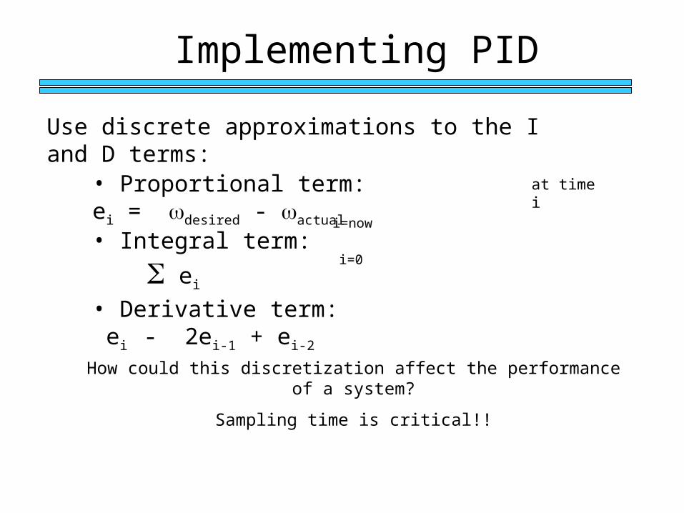
Use discrete approximations to the I and D terms:
• Proportional term: ei = desired - actual
• Integral term: ei
at time i
i=0
i=now
• Derivative term: ei - 2ei-1 + ei-2
How could this discretization affect the performance of a system?
Sampling time is critical!!
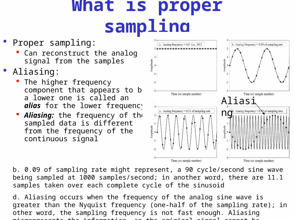
What is proper sampling Proper sampling:
Can reconstruct the analog signal from the samples
Aliasing: The higher frequency component
that appears to be a lower one is called an alias for the lower frequency
Aliasing: the frequency of the sampled data is different from the frequency of the continuous signal
b. 0.09 of sampling rate might represent, a 90 cycle/second sine wave being sampled at 1000 samples/second; in another word, there are 11.1 samples taken over each complete cycle of the sinusoid
d. Aliasing occurs when the frequency of the analog sine wave is greater than the Nyquist frequency (one-half of the sampling rate); in other word, the sampling frequency is not fast enough. Aliasing misrepresents the information, so the original signal cannot be reconstructed properly from the samples.
Aliasing
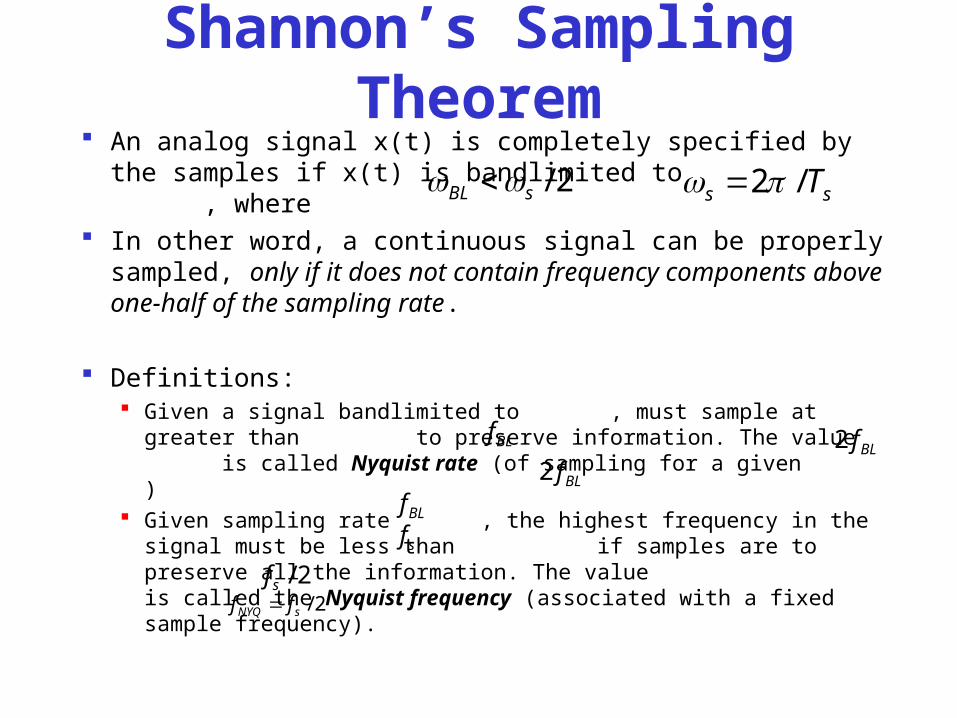
Shannon’s Sampling Theorem An analog signal x(t) is completely specified by the samples
if x(t) is bandlimited to , where In other word, a continuous signal can be properly sampled,
only if it does not contain frequency components above one-half of the sampling rate.
Definitions: Given a signal bandlimited to , must sample at greater than
to preserve information. The value is called Nyquist rate (of sampling for a given )
Given sampling rate , the highest frequency in the signal must be less than if samples are to preserve all the information. The value is called the Nyquist frequency (associated with a fixed sample frequency).
2/sBL ss T/2
BLfBLf2
BLf2
BLf
sf
2/sf2/sNYQ ff
Rule of Thumb For a closed-loop control system, a typical
choice for the sampling interval T based on rise time is 1/5 th or 1/10 th of the rise time. (i.e., 5 to 10 samples for rise time)
Motor Drive Micro-controller
Logic Level
Motor Drive Components Power transistors H-Bridge Drivers etc ...
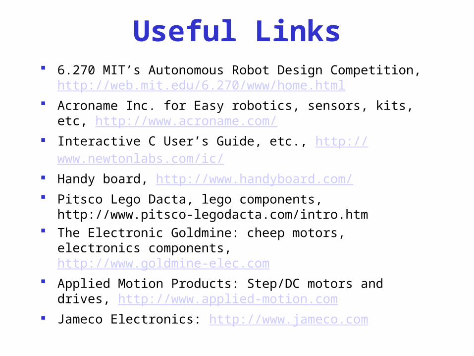
Useful Links 6.270 MIT’s Autonomous Robot Design Competition,
http://web.mit.edu/6.270/www/home.html Acroname Inc. for Easy robotics, sensors, kits, etc,
http://www.acroname.com/ Interactive C User’s Guide, etc., http://www.newtonlabs.com/ic/ Handy board, http://www.handyboard.com/ Pitsco Lego Dacta, lego components, http://www.pitsco-
legodacta.com/intro.htm The Electronic Goldmine: cheep motors, electronics components,
http://www.goldmine-elec.com Applied Motion Products: Step/DC motors and drives,
http://www.applied-motion.com Jameco Electronics: http://www.jameco.com
Assignment Refresh you memory
Control Theory (Text book: K. Ogata, Modern Control Engineering, Prentice Hall)
Electronics (OP-amp, motor drive)
Laboratory Specs of Motors Motor Drive Circuit Looking for Drive Components


