15
Motors, bearings & Sensors By Peter Lau
| Date post: | 29-Dec-2015 |
| Category: |
Documents |
| Upload: | junior-page |
| View: | 235 times |
| Download: | 4 times |
Motors, bearings & Sensors
By Peter Lau
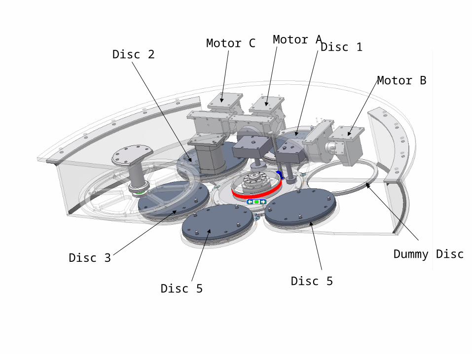
Disc 2Disc 1
Dummy Disc
Disc 5
Disc 3
Disc 5
Motor A
Motor B
Motor C
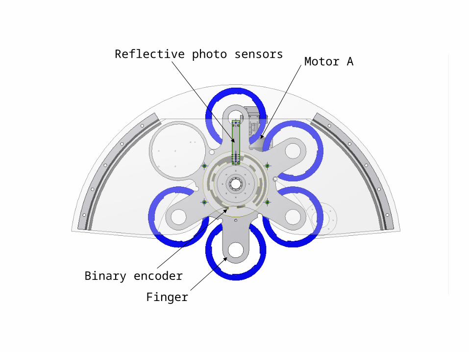
Binary encoder
Motor A
Finger
Reflective photo sensors
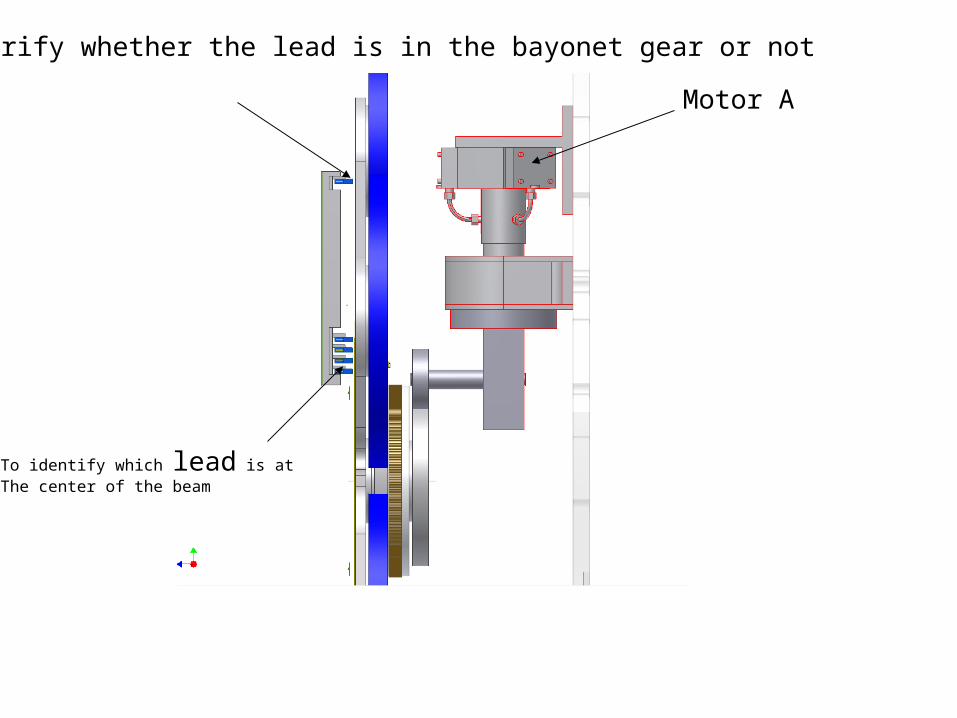
To verify whether the lead is in the bayonet gear or not
To identify which lead is atThe center of the beam
Motor A

Motor B to drive to turnthe disc holder 15° clockwise& anti-clockwise
Encoder
Encoder Reader
Bayonet Gear;Turn 15° to clockwise to unlock and anti-Clockwise to lock

This bayonet gear is to drive the diffuser catcher forward and backward
Motor C
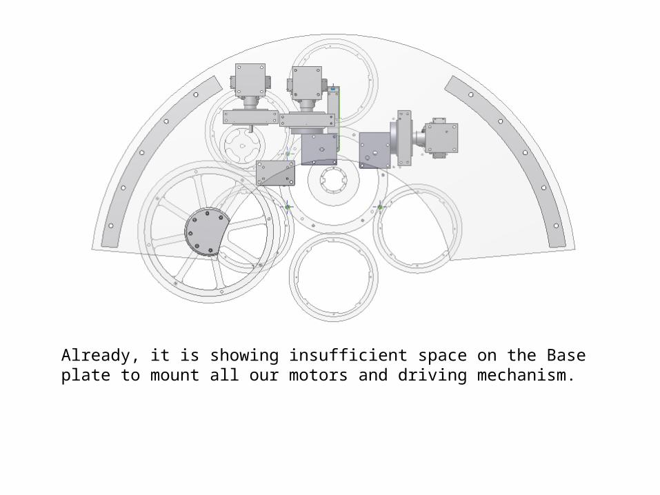
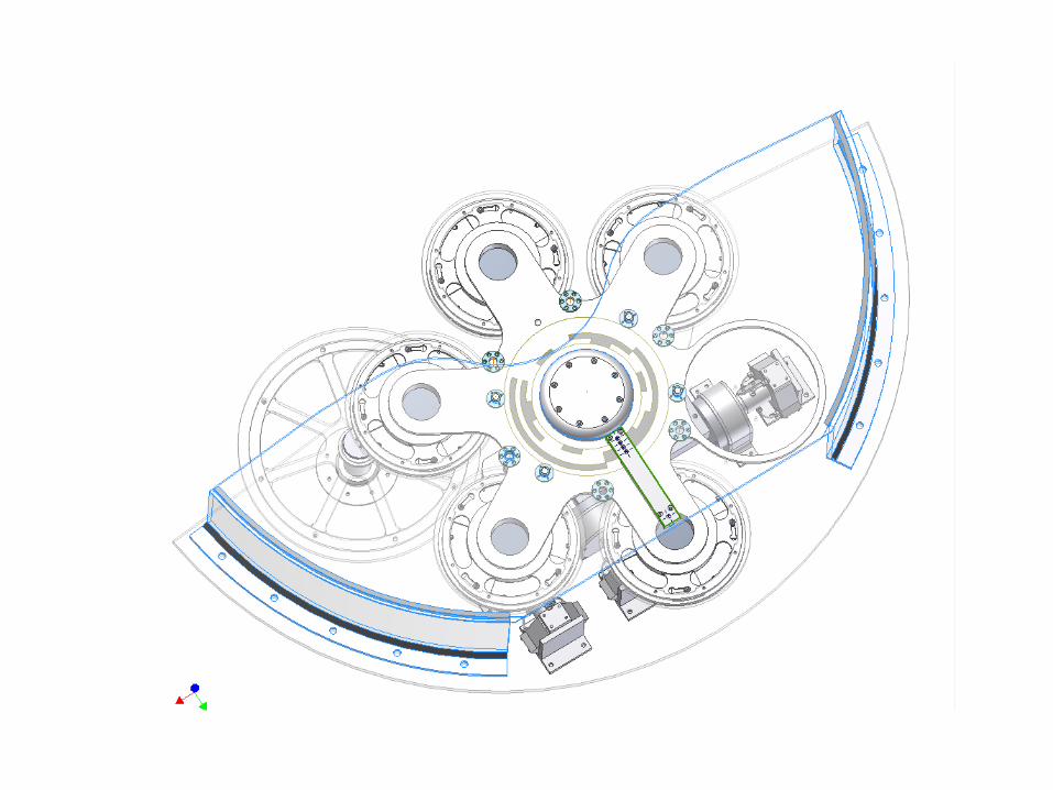
Already, it is showing insufficient space on the Base plate to mount all our motors and driving mechanism.
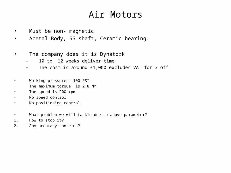
Air Motors
• Must be non- magnetic• Acetal Body, SS shaft, Ceramic bearing.
• The company does it is Dynatork– 10 to 12 weeks deliver time
– The cost is around £1,000 excludes VAT for 3 off
• Working pressure – 100 PSI• The maximum torque is 2.8 Nm• The speed is 200 rpm• No speed control• No positioning control
• What problem we will tackle due to above parameter?
1. How to stop it?
2. Any accuracy concerns?
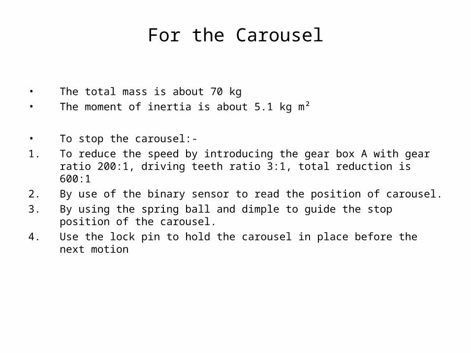
For the Carousel
• The total mass is about 70 kg • The moment of inertia is about 5.1 kg m²
• To stop the carousel:-
1. To reduce the speed by introducing the gear box A with gear ratio 200:1, driving teeth ratio 3:1, total reduction is 600:1
2. By use of the binary sensor to read the position of carousel.
3. By using the spring ball and dimple to guide the stop position of the carousel.
4. Use the lock pin to hold the carousel in place before the next motion

This encoder can be a stick type or justPainting on the top .
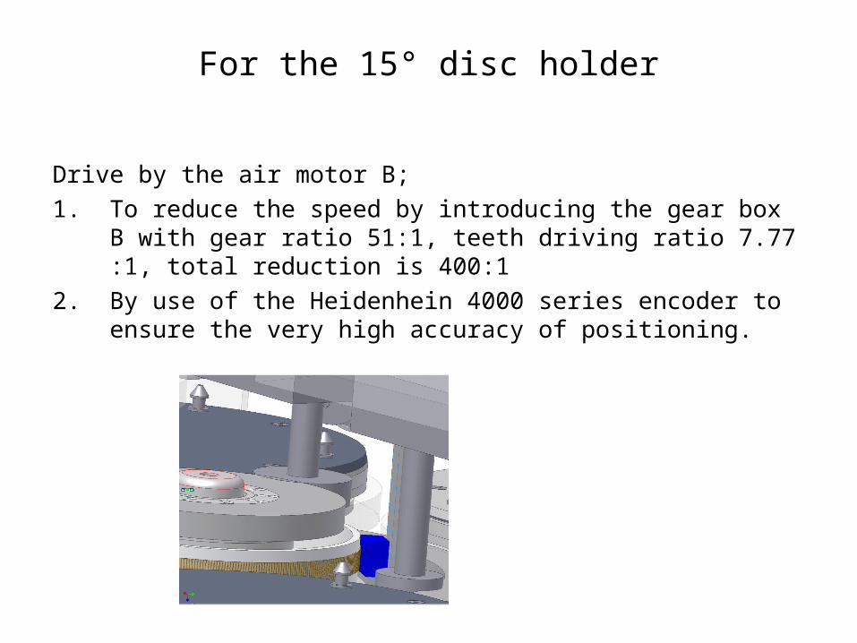
For the 15° disc holder
Drive by the air motor B;
1. To reduce the speed by introducing the gear box B with gear ratio 51:1, teeth driving ratio 7.77 :1, total reduction is 400:1
2. By use of the Heidenhein 4000 series encoder to ensure the very high accuracy of positioning.
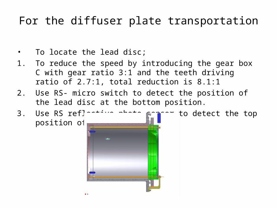
For the diffuser plate transportation
• To locate the lead disc;
1. To reduce the speed by introducing the gear box C with gear ratio 3:1 and the teeth driving ratio of 2.7:1, total reduction is 8.1:1
2. Use RS- micro switch to detect the position of the lead disc at the bottom position.
3. Use RS reflective photo sensor to detect the top position of the lead disc.
The Bearings
• The bearings are all in stainless steel type from Kaydon• Totally 11 bearings are required.• The cost of bearing will be about £3,400 plus VAT (estimation only)• The delivery of some of the bearing may be long according to the feedback from the sales representative. Initial
statement from him for the delivery time is October. And he is still bargaining with the factory.
The Sensors• 2 micro switch, 5 reflective type photo diode, 1 reflective type photo sensor & 2 encoder• The cost of sensors have not quoted yet.
Summary
• The detail design is not yet finished. Details needed to be drawn later.
• Changes to the mounting supports for the motors and the locking mechanism may need to be revised to fit into the existing base plate, the size of which is fixed
• The sourcing activities of the sensors has not started yet.• The control interface such as valves, fittings, counters and CPU
need to be added• The gearbox design is under process by J. Tacon.


