WM’05 Conference, February 27–March 3, 2005, Tucson, AZ MOUND PLANT SW-17 & SW-19 OLD CAVE FACILITIES ADVANCED TRUPRO ® SUBSURFACE SAMPLING G. Charters, S. Aggarwal, D. Thacker New Millennium Nuclear Technologies, 575 Union Blvd, Suite 102, Lakewood, CO 80228, J. Gill U.S. DoE MEMP, P.O. Box 3030, Miamisburg, OH 45343-3030 ABSTRACT The concrete and subsurface profiling technology, TRUPRO ® was deployed to sample the subsurface materials beneath rooms SW-17 and SW-19 at the Old Cave, Mound Plant, Ohio. CH2MHILL is engaged in the closure of Mound Plant Technology Site by 2006. Acceleration of the pace of cleanup at the site requires a program of effective and focused action; one that is paramount to a safe and economically viable site closure. A suite of innovative characterization, subsurface access, modeling, and visualization tools provided very limited success at eliminating historical unknowns within the Old Cave facility and certainty and confidence were required from a radiological safety perspective in disposing of the buildings subsurface contaminated materials. The subsurface profiling technology penetrated many locations and layers of materials to depths of nine feet obtaining 97 separate samples including powdered concrete and metal fine shaving samples from the Old Cave facility structures. Sampling was in the vertical direction downward into the floors and subsurface building structures to acquire representative samples of buried subsurface metal objects including cave shielding doors, end shield plates, crane rails, portions-sections of the cave structure, cave structure concrete footer base and subsurface bedrocks and soils. Some sampling was at angles from a perpendicular orientation to a wall or floor surface to obtain samples from inaccessible depths within the structure. Drill guides and mounting equipment were used to achieve these sampling angles. All of the retrieved powdered samples were initially assessed semi quantitatively by hand held probe and measured quantitatively using ISOCS for specific radionuclide activities of interest, specifically Radium- 226, Actinium-227, Radon and daughters, Potassium-40 and Thorium-228, 229, 230. TRUPRO ® has four major components: a drill with a specialized concrete / metal cutting and sampling head, drill bits, a sample collection unit and a vacuum pump. The drill head is used under hammer action to penetrate hard surfaces causing the bulk material to be pulverized as the drill travels through the radioactive media, efficiently transmitting to the sampling unit a representative sample of powdered bulk material that prevents cross contamination of the clean retrieved samples. The data quality, quantity, and representativeness were used to produce an activity profile from the surface into the bulk building material. The activity data obtained was reduced and transferred to building drawings which may then be expanded to ultimately characterize the facility and safely expedite waste segregation and facility closure at a reduced cost and risk.
Transcript
WM’05 Conference, February 27–March 3, 2005, Tucson, AZ
MOUND PLANT SW-17 & SW-19 OLD CAVE FACILITIES ADVANCED TRUPRO®
SUBSURFACE SAMPLING
G. Charters, S. Aggarwal, D. Thacker New Millennium Nuclear Technologies,
575 Union Blvd, Suite 102, Lakewood, CO 80228,
J. Gill U.S. DoE MEMP,
P.O. Box 3030, Miamisburg, OH 45343-3030
ABSTRACT The concrete and subsurface profiling technology, TRUPRO® was deployed to sample the subsurface materials beneath rooms SW-17 and SW-19 at the Old Cave, Mound Plant, Ohio. CH2MHILL is engaged in the closure of Mound Plant Technology Site by 2006. Acceleration of the pace of cleanup at the site requires a program of effective and focused action; one that is paramount to a safe and economically viable site closure. A suite of innovative characterization, subsurface access, modeling, and visualization tools provided very limited success at eliminating historical unknowns within the Old Cave facility and certainty and confidence were required from a radiological safety perspective in disposing of the buildings subsurface contaminated materials. The subsurface profiling technology penetrated many locations and layers of materials to depths of nine feet obtaining 97 separate samples including powdered concrete and metal fine shaving samples from the Old Cave facility structures. Sampling was in the vertical direction downward into the floors and subsurface building structures to acquire representative samples of buried subsurface metal objects including cave shielding doors, end shield plates, crane rails, portions-sections of the cave structure, cave structure concrete footer base and subsurface bedrocks and soils. Some sampling was at angles from a perpendicular orientation to a wall or floor surface to obtain samples from inaccessible depths within the structure. Drill guides and mounting equipment were used to achieve these sampling angles. All of the retrieved powdered samples were initially assessed semi quantitatively by hand held probe and measured quantitatively using ISOCS for specific radionuclide activities of interest, specifically Radium-226, Actinium-227, Radon and daughters, Potassium-40 and Thorium-228, 229, 230. TRUPRO® has four major components: a drill with a specialized concrete / metal cutting and sampling head, drill bits, a sample collection unit and a vacuum pump. The drill head is used under hammer action to penetrate hard surfaces causing the bulk material to be pulverized as the drill travels through the radioactive media, efficiently transmitting to the sampling unit a representative sample of powdered bulk material that prevents cross contamination of the clean retrieved samples. The data quality, quantity, and representativeness were used to produce an activity profile from the surface into the bulk building material. The activity data obtained was reduced and transferred to building drawings which may then be expanded to ultimately characterize the facility and safely expedite waste segregation and facility closure at a reduced cost and risk.
WM’05 Conference, February 27–March 3, 2005, Tucson, AZ
INTRODUCTION The Old Cave at Mound Plant, Ohio facilities must be dismantled and the demolition wastes sized into manageable pieces for handling, disposal and reduced risk liability. The Old Cave at Mound was constructed in the early 1950s and occupied an approximate 1,000-ft2 area located in the Semi-Works (SW) Building. This area was used to process radium (Ra-226) and actinium (Ac-227) from 1951 to 1955. The radionuclides and their respective compounds which were expected to be encountered during the disposition of the Old Cave entombment include: Radium-226, Actinium-227, Radium Bromide, Actinium Bromide, Radon and daughters, Radium Carbonate, Radium Nitrate, Actinium Oxalate, Potassium-40, and Thorium-228, 229, & 230.
To facilitate radioactive material characterization and remediation of the Old Cave entombment at the DOE-Miamisburg Environmental Management Program (MEMP) in Ohio, CH2MHill required a tool capable of profiling the truly unique and extraordinary building configuration of the varied layers of separations process bulk building materials to depth. TECHNICAL FIELD The intent of the deployment was to sample and to detect radioactive contamination at depth within the building material matrix, for it will eliminate historical unknowns and increase worker safety awareness and reduce risks of demolition and waste shipment. A suite of innovative characterization, subsurface access, modeling, and visualization tools provided very limited success at eliminating these historical unknowns. This technology is a specialized bulk material radiochemical profiling drilling technology and has four major components: a drill with a specialized cutting and sampling head, drill bits, a sample collection unit and a vacuum pump. The TRUPRO®
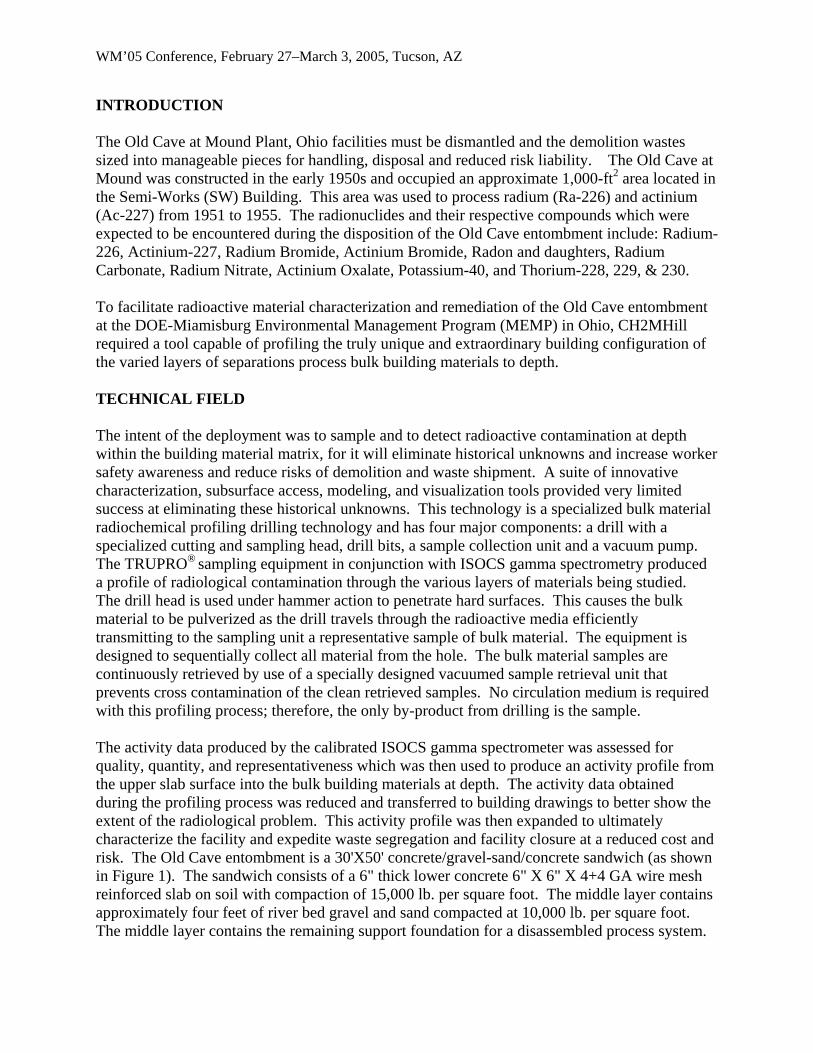
sampling equipment in conjunction with ISOCS gamma spectrometry produced a profile of radiological contamination through the various layers of materials being studied. The drill head is used under hammer action to penetrate hard surfaces. This causes the bulk material to be pulverized as the drill travels through the radioactive media efficiently transmitting to the sampling unit a representative sample of bulk material. The equipment is designed to sequentially collect all material from the hole. The bulk material samples are continuously retrieved by use of a specially designed vacuumed sample retrieval unit that prevents cross contamination of the clean retrieved samples. No circulation medium is required with this profiling process; therefore, the only by-product from drilling is the sample. The activity data produced by the calibrated ISOCS gamma spectrometer was assessed for quality, quantity, and representativeness which was then used to produce an activity profile from the upper slab surface into the bulk building materials at depth. The activity data obtained during the profiling process was reduced and transferred to building drawings to better show the extent of the radiological problem. This activity profile was then expanded to ultimately characterize the facility and expedite waste segregation and facility closure at a reduced cost and risk. The Old Cave entombment is a 30'X50' concrete/gravel-sand/concrete sandwich (as shown in Figure 1). The sandwich consists of a 6" thick lower concrete 6" X 6" X 4+4 GA wire mesh reinforced slab on soil with compaction of 15,000 lb. per square foot. The middle layer contains approximately four feet of river bed gravel and sand compacted at 10,000 lb. per square foot. The middle layer contains the remaining support foundation for a disassembled process system.
WM’05 Conference, February 27–March 3, 2005, Tucson, AZ
The foundation is comprised of two footers, one at 14" X 35-3/4" X 29' and the other at 17" X 35-3/4" X 29'. Both footers contain 6" X 6" X 6+6 GA wire mesh. The footers are capped by a steel plate and are considered as part of the 35-3/4" height. The top concrete slab is 10" thick and contains a 4" X 4" X 4 + 4 GA wire mesh. Additional re-bar support was used over the abandoned process system foundation area. The area is reinforced with 1/2" re-bar at 12" center to center in both directions, 3/4 of an inch in from the bottom and top of the slab.
Fig. 1. Cross section profile SW-17 / SW-19 Old Cave surface to 113-in. depth.
Various items from the Old Cave were buried within the entombment structure including, but not
• Cave shielding doors
il
f the Cave structure
crete footer base.
To establish a knowledge base for the Old Cave entombment and ensure a sound design for its
limited to the following:
• End shield plates • Crane and crane ra• Manipulator units • Portions-sections o• Refrigeration unit • Cave structure con
remediation and removal, non-intrusive geophysical techniques were used initially during PhaseI Characterization but were not very successful. The following suite of innovative
WM’05 Conference, February 27–March 3, 2005, Tucson, AZ
characterization, subsurface access, modeling, and visualization tools provided very limited success at eliminating historical unknowns:
• In situ Object Counting System (ISOCS) provided real-time characterization of subsurface soils and collected soil samples.
• Ground penetrating Radar and Time-Domain Electromagnetics to characterize the location of footers, unknown objects, wetted soils and overall positioning of materials under foundations.
• 3-D modeling and visualization to optimize sampling and graphically represent results. • Diamond Core Drilling to cut through concrete to provide direct access to soils under
buildings. • Small footprint Geoprobe with a real-time Position Location (POLO) to obtain samples
from most likely locations of contaminants.
Phase II sampling and characterization was through core-holes into the upper layer of concrete slab and gravel and used a Geoprobe. There were problems achieving 4 feet of penetration, retrieval of deep samples and the placement of plastic sleeving as the probe was withdrawn were difficult as the material being sampled caved into the hole before the plastic liner could be inserted or the stones were to big to penetrate at most sample point locations.
The equipment consisted of a drill and drill guide, specialized hollow concrete and metal cutting drill bits, vacuum pump, and sampling train to sample the subsurface materials beneath rooms SW-17 and SW-19. The location of these holes was determined by site personnel. Offset drill holes were attempted when at locations where metal or other material, was encountered. Phase III sampling gained access below the upper slab of SW-19, or via exposed gravel, at locations 1, 3, 7, 7A, 9, 10, 14, 15A, 21, and 24, through 41. The actual materials encountered at a given location varied. Samples were collected from the gravel fill at the concrete cap interface, sump and trench concrete caps, sump and trench sand fill, lower (SW-1A) slab, including 2” cap in hot cell interior and on west floor, 2 sequential one-foot increments of soil below the lower slab, the hot cell foundation, and any hardware objects embedded in the gravel that were encountered during drilling. Sampling used a hollow 12mm drill bit technology in which the sampled matrix is powdered by drilling, with powder extracted pneumatically from the base of the drilled hole and collected onto 4 micron cartridge filters with 0.01 micron secondary cartridge in series for total particulate capture. Sample from each layer of matrix (e.g., fill, cap, sand, slab, metal plate, soil increments) was captured individually. Each location accommodated one successful drill-hole collecting samples for radionuclide analysis. Sampling at locations 1, 3, 7, 7A, 9, 10, 14, 15A, 21, and 24 was executed vertically from above the upper slab or gravel fill. At locations 3 and 24, gravel had been partially removed to enable vertical sampling from ~2 feet below the level of the upper slab. Sampling at locations 26 and 27 began at the SW-1A elevation.
WM’05 Conference, February 27–March 3, 2005, Tucson, AZ
Abandoned steel hardware objects, such as door panels or rails from the original SW-1A hot cell, were encountered during drilling through gravel at locations 1, 3, 7, 7A, 9, 10, 14, 15A, 21, and 24. The gravel was collected during initial approach to the metal object and bottled separately. Having penetrated through the hardware object it was possible to collect the underlying structural materials (lower slab, bituminous material soils and bedrock. The surfaces of the steel objects encountered (whether by original or offset drill-hole) were sampled by a special 25 mm diameter hollow metal cutting drill bit. Samples of Old Cave hot cell subsurface foundation vertical walls, both interior and exterior, were obtained by means of ~45 degree angle-drilling in conjunction with drill bit sleeving. This was performed through the gravel fill that had been exposed by removal of the upper slab at sampling locations 28 – 41 shown on Figure 2. Samples were then collected from the wall surfaces at each sampling location by drilling ~1” deep holes at 6 or more nearby points of impact, all points contributing to the collected sample from a given location. An estimate of the depth of sampling of the foundation at each such sampling location was logged. NMNT performed phase III sample collection from the gravel, lower (SW-1A) slab, sumps, trenches and the soil / bedrock below them at each hole location. Drilling and sampling using TRUPRO® were performed without the use of water and without the use of fugitive dust minimization techniques. A half-inch thick metal plate spanned over cut slab sections allowing the positioning of a man lift or spanning gantry system to allow safe access and anchorage of drilling mechanism using longer drill bit lengths. Samples were placed into 125cc clear glass containers with Teflon lid liners. Sample container labels and chain-of-custody sheets were provided by NMNT. Each layer of medium encountered was sampled and bulked individually, and the soil and bedrock beneath the original concrete was sampled in 2 sequential 1-foot increments. Samples collected were counted for initial gamma analysis by ISOCS. All drilling observations were logged along with the sample locations, the sampling methodologies, the resulting sample mass data, the estimated surface areas abraded from hardware objects and description of sample depth and composition. Profiling Objectives Profiling and sampling the subsurface materials beneath rooms SW-17 and SW-19 at Mound Plant, Ohio to depth included the following desired capabilities and design features of the equipment:
1. An ability to remove samples of concrete using a specialized tungsten carbide and metal
cutting drilling technology. 2. Collection of all concrete, sand, soil, bedrock and metal particulate from sampling
operations into a specialized filter unit. 3. To be powered with commonly available electric power.
WM’05 Conference, February 27–March 3, 2005, Tucson, AZ
4. Able to remove 1-in. depth of potentially contaminated concrete, soil/bedrock sequentially from depths of less than an inch to 9 feet.
5. Produce representative samples in a powdered form for optimal counting efficiency by an
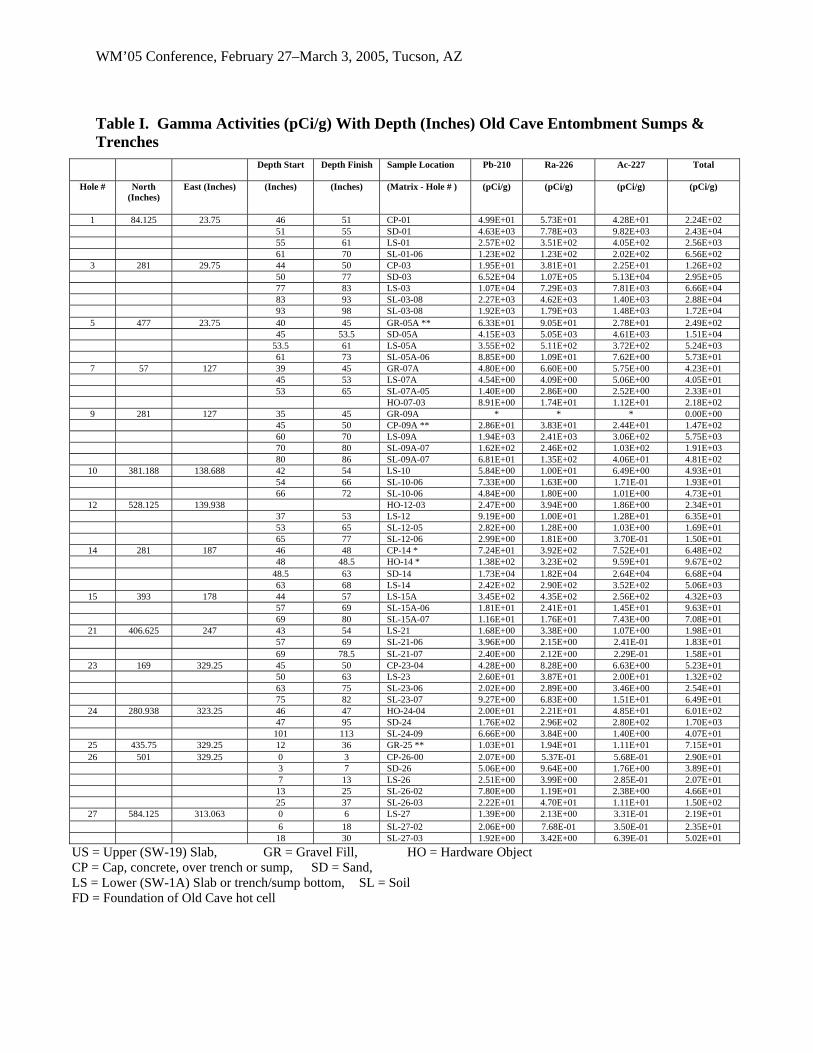
ISOCS gamma spectrometry system. 6. Able to operate in an ambient temperature environment. Radiochemical Profiling Figure 2 shows the Old Cave sampling locations. There was a need to sample at depth within the building material matrix and eliminate historical uncertainties to reduce D&D risk. The approach to sample acquisition through varying layers of different material types and obtain a dry representative sample at 1-inch resolution was key to achieving these goals. This technology employed a heavy duty 110 V hammer action drill that rapidly penetrated the concrete surface to precise predetermined depths. The powder or metal particulate generated at the depth of penetration into the bulk building material was immediately extracted away from the specialized tungsten carbide drill bit by high vacuum and collected in an inline filter unit for radioanalysis. The sample was in a powder form and was therefore easier to place in the correct geometry for optimal calculation of the matrix activity. The reduced downtime associated with sampling and characterization increases productivity, decreases costs and risks, and most importantly increasing worker awareness of the radiological area. This technology has a high sampling tolerance and depth resolution and significantly reduced the chances of cross contamination of samples. Sample Analysis Radium-226, Lead-210 and Actinium-227 were measured with Gamma spectrometry using an ISOCS HPGe detector in conjunction with gamma analysis software. A calibration check for the HPGe gamma detector was performed using a NIST Mixed Multiple Nuclide Radioactive source to verify instrument performance. As shown in Tables I and II there was significant contamination levels within the concrete process structure at the points sampled, most samples were calculated to be above background activity levels. The results are presented graphically in Figure 3.
WM’05 Conference, February 27–March 3, 2005, Tucson, AZ
VCP is situated below SW-1A slab
31 32
o 17A
28
37 36
33
40
35 34
30
39 38 41 15A o
29
SW-19 elevation is ~48” above SW-1A
level
SW-17 elevation is same as SW-
Drain lines that havebeen removed
o 19A
Fig. 2
. Plan View
1A level
of SW-17 / SW-19 Old Cave Sample Locations
WM’05 Conference, February 27–March 3, 2005, Tucson, AZ
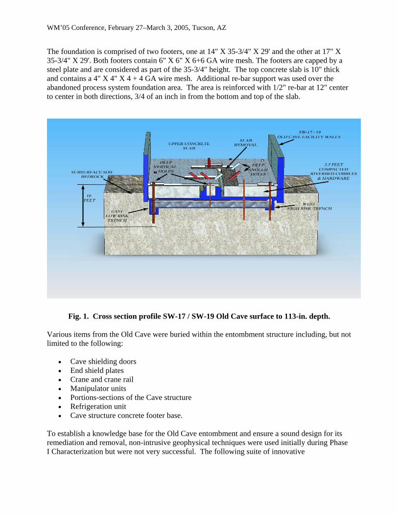
Table I. Gamma Activities (pCi/g) With Depth (Inches) Old Cave Entombment Sumps & Trenches
Depth Start Depth Finish Sample Location Pb-210 Ra-226 Ac-227 Total
US = Upper (SW-19) Slab, GR = Gravel Fill, HO = Hardware Object CP = Cap, concrete, over trench or sump, SD = Sand, LS = Lower (SW-1A) Slab or trench/sump bottom, SL = Soil FD = Foundation of Old Cave hot cell
WM’05 Conference, February 27–March 3, 2005, Tucson, AZ
Table II. Gamma Activities (pCi/g) With Depth (Inches) Old Cave Foundation Depth Start Sample Location Pb-210 Ra-226 Ac-227 Total
US = Upper (SW-19) Slab, GR = Gravel Fill, HO = Hardware Object CP = Cap, concrete, over trench or sump, SD = Sand, LS = Lower (SW-1A) Slab or trench/sump bottom, SL = Soil FD = Foundation of Old Cave hot cell
WM’05 Conference, February 27 – March 3, 2005, Tucson, AZ
Fig. 3. Total gamma activity (pCi/g) v. depth (Inches)
CONCLUSIONS AND RECOMMENDATIONS A summation of radionuclide activity was performed by extrapolating concentrations over all Old Cave entombment structural materials. This resulted in a significant (150-fold) reduction to previously estimated radionuclide inventory. A similar reduction in radiological hazard was therefore anticipated for the removal of the Old Cave entombment during demolition of the Miamisburg Closure Project's SW Building. Rather than remotely operated demolition of the entombment under tightly controlled, contained, and monitored conditions, much less restrictive demolition became feasible. This resulted in a cost saving of approximately $500,000 and time saving of approximately 4 months in schedule. The biggest advantage of pursuing this sampling approach was the improved approach to sample acquisition and thus be able to penetrate to greater depths through varied layering of different materials of diverse physical characteristics and obtain samples to quantify the contents of Pandora’s Box prior to facility demolition. The no sampling or characterization approach would have meant accessing the contamination area, inherently causing delays in building material
WM’05 Conference, February 27 – March 3, 2005, Tucson, AZ
removal as anomalies of activity levels at the various critical locations of the historical process structure were unearthed so increasing project turn-around time, and radiological risk. The downtime associated with these delays reduces productivity, increases costs, and most importantly, delays worker awareness of the area. Based on the samples evaluated, the following conclusions and recommendations can be made: 1. There was no high gamma contamination within the upper concrete slab, the underlying
3.5 feet of river bed stones, buried objects and soil nor the lower cap concrete slab at the points sampled, although certain samples were calculated to be above background activity levels.
2. The detailed and extensive sampling regime into previously inaccessible waste volumes
proved the working trench and sump bottoms along with sand fill material were highly contaminated, the west side of the process being an order of magnitude higher in activity than the east side of the process. Anomalous activity found in the east trench and sump were caused by an historical overflow of process material from the west trench to the east trench on process startup caused by an incorrect gradient of the sloping west – east transect trench on building construction.
3. The concrete sampling and profiling technology produced high quality, representative
samples, so that the radioanalysis was reliable. 4. Confidence is greatly increased in radiological safety and in D&D operations by
eliminating previously undeterminable historical unknowns. 5. By using TRUPRO® a highly adaptive rapid sampling mechanism and profiling approach
in conjunction with an HPGe Gamma Spectrometer, historical unknowns of radwaste activities, volumes and risk reduction of various segregated waste streams was achieved. Operating requirements for the tool included the production of representative samples of riverbed gravel and cobbles, concrete, metal plate, sand, subsurface soils and bedrock material. The sampling tool was able to penetrate through multiple layers of varied materials, rapidly, with a simple and economical operation, and operated in ambient temperatures. All operations were conducted in compliance with applicable nuclear site regulations.
Most importantly the concrete sampling and profiling technology in conjunction with the ISOCS gamma spectrometer, significantly improved technical awareness of the contamination of subsurface materials including underlying bedrock and soils up to 2 feet under the lower concrete slab foundation indicating an ingress of activity from the trenches and sumps.