36
Mounting and Operating Instructions EB 8385 EN Edition July 2012 Pneumatic Positioner Electropneumatic Positioner Type 3760 Type 3760 Positioner

Mounting andOperating Instructions
EB 8385 ENEdition July 2012
Pneumatic PositionerElectropneumatic PositionerType 3760
Type 3760 Positioner

Contents
1 Design and principle of operation. . . . . . . . . . . . . . . . . . . . 6
2 Attachment to actuators . . . . . . . . . . . . . . . . . . . . . . . . 82.1 Adjusting the operating direction . . . . . . . . . . . . . . . . . . . . 82.2 Installing the clamp . . . . . . . . . . . . . . . . . . . . . . . . . . 10
3 Connections . . . . . . . . . . . . . . . . . . . . . . . . . . . . . . 133.1 Pneumatic connections . . . . . . . . . . . . . . . . . . . . . . . . . 133.1.1 Signal pressure indication . . . . . . . . . . . . . . . . . . . . . . . 133.1.2 Supply pressure . . . . . . . . . . . . . . . . . . . . . . . . . . . . 133.1.3 Degree of protection IP 65 . . . . . . . . . . . . . . . . . . . . . . . 133.2 Electrical connections . . . . . . . . . . . . . . . . . . . . . . . . . 143.2.1 Switching amplifier . . . . . . . . . . . . . . . . . . . . . . . . . . 14
4 Operation – Setting . . . . . . . . . . . . . . . . . . . . . . . . . . 154.1 Starting point and reference variable . . . . . . . . . . . . . . . . . . 154.2 Adjustment for "Actuator stem extends". . . . . . . . . . . . . . . . . 164.3 Adjustment for "Actuator stem retracts" . . . . . . . . . . . . . . . . . 17
5 Adjusting the limit switch . . . . . . . . . . . . . . . . . . . . . . . 185.1 Retrofitting a limit switch . . . . . . . . . . . . . . . . . . . . . . . . 18
6 Converting the positioner . . . . . . . . . . . . . . . . . . . . . . . 206.1 Conversion from pneumatic p/p to electropneumatic i/p . . . . . . . . 206.2 Conversion from electropneumatic i/p to pneumatic p/p . . . . . . . . 21
7 Dimensions in mm. . . . . . . . . . . . . . . . . . . . . . . . . . . 22
2 EB 8385 EN
Contents

EB 8385 EN 3
Safety instructions
� The positioner is to be mounted, started up or operated only by trained andexperienced personnel familiar with the product.According to these Mounting and Operating Instructions, trained personnel re-fers to individuals who are able to judge the work they are assigned to andrecognize possible dangers due to their specialized training, their knowledgeand experience as well as their knowledge of the applicable standards.
� Explosion-protected versions of this positioner may only be operated by per-sonnel who have undergone special training or instructions or who are autho-rized to work on explosion-protected devices in hazardous areas.
� Any hazards that could be caused by the process medium, the operating pres-sure, the signal pressure or by moving parts of the control valve are to be pre-vented by means of the appropriate measures. If inadmissible motions or for-ces are produced in the actuator as a result of the supply pressure, the supplypressure must be restricted by means of a suitable supply pressure reducingstation.
� Proper shipping and appropriate storage are assumed.
� Note: The device with a CE marking fulfils the requirements of the Directives94/9/EC (ATEX) and 89/336/EEC (EMC). The declaration of conformity isavailable on request.

4 EB 8385 EN
Versions
Positioner Type 3760- X X X X X X
Explosion protection WithoutII 2G Ex ia IIC T6 acc. to ATEXCSA/FMII 3G Ex nA II T6 acc. to ATEX
0138
Additional equipment WithoutInductive proximity switches
01
Pneumatic connections G 18
18 NPT
12
Electrical connections WithoutM20 x 1.5 blueM20 x 1.5 blackConnector DIN 43650
0123
Reference variable 0.2 to 1 bar/3 to 15 psi4 to 20 mA with i/p module 61090 to 20 mA with i/p module 61121 to 5 mA with i/p module 6112
0122
0123

EB 8385 EN 5
Technical data
Travel range 0 to 5 mm · 0 to 7.7 mm · 0 to 15 mm(see page 11 for range spring table)
Reference variable pneumatic 0.2 to 1.0 bar (3 to 15 psi)
electric 4 to 20 mA (also 0 to 20 mA with 6112 i/p module) · 1 to 5 mA
Split-range operation0 to 50 % or50 to 100 %with 7.5 and 15 mm travel
Internal resistance at 20 °C4 to 20 mA: 200 � for safe areas · 250 � for hazardous areas0 to 20 mA: 200 �
1 to 5 mA: 850 �
Supply air 1.4 to 6 bar (20 to 90 psi)
Signal pressure 0 to 6 bar (0 to 90 psi)
Characteristic Linear, deviation from terminal-based conformity � 1.5 %
Direction of action Reversible
Hysteresis � 0.5 %
Sensitivity � 0.1 %
Steady-state air consumption � 100 ln/h at 0.6 bar signal pressure and supply pressure up to 6 bar
Air output capacity At �p 1.4 bar: 1600 ln/h · At �p 6 bar: 5000 ln/h
Transit times with Type 3277 Actuator(15 mm travel, 0.2 to 1 bar signalpressure)
120 cm²: � 2 s · 240 cm²: � 6 s · 350 cm²: � 8 s
Permissible ambient temperature
–20 to +70 °CDown to –30 °C with metal cable glandDown to –40 °C with metal cable gland and Type 6112 i/p ConverterLimits in test certificates additionally apply for explosion-protected devices.–40 to +70 °C for Type 3760-00x000 Pneumatic Positioner without inducti-ve limit switch
InfluenceTemperature: zero point: � 0.03 %/°C · Span: � 0.03 %/°CVibrations: between 5 and 120 Hz as well as 2 g � 0.5 %Supply air: � 0.6 %/1 bar
Electromagnetic compatibility Requirements specified in EN 61000-6-2, EN 61000-6-3 and EN 61326-1fulfilled
Variable position when turned 180° < 3.5 %
Degree of protection IP 54 (IP 65 with filter check valve, refer to accessories)
Weight Approx. 0.6 kg
Materials Housing: polyamide · External parts: stainless steel
Additional electrical equipment
Inductive limit switch Type SJ2-SN
Control circuit Values corresponding to downstream switching amplifier
Hysteresis at rated travel � 1 %

1 Design and principle ofoperation
The pneumatic or electropneumaticpositioner ensures a preselected assignmentof the valve stem position (controlled vari-able x) to the control signal (reference vari-able w).
The input signal received from a control unitis compared to the travel of the controlvalve, and a corresponding pneumatic sig-nal pressure (output variable) is produced.
The positioner mainly consists of a pneu-matic unit including a clamp (10), rangespring (7), diaphragm lever (4) and abooster (12) with a double plug (13).
The electropneumatic positioner is addition-ally equipped with an electropneumatic con-verter (2).
The positioner is designed for direct attach-ment to SAMSON Type 3277 Actuators.
The control signal from the control unit, pro-vided it is a pneumatic signal, is applied di-rectly to the measuring diaphragm (3) aspressure signal pe. Whereas a DC currentinput signal in the range of 4 to 20 mA, forexample, is directly passed on to theelectropneumatic converter (i/p converter),where it is converted into a proportionalpressure signal pe.
The pressure signal pe produces a force onthe measuring diaphragm (3), which is bal-anced by the force of the range spring (7).The deflection of the diaphragm (3) causesthe diaphragm lever (4) to move. The doubleplug (13) in the booster (12) follows this mo-tion, producing a signal pressure pst.
The operating direction of the signal pres-sure, either increasing >> or <> decreasingwhen the input signal increases, depends onthe position of the booster which can be ro-tated by 180°.
A change in either the input signal or thevalve position causes a pressure change inthe booster. The output pressure pst of thebooster moves the plug stem to a positioncorresponding with the given control signal(reference variable).
The adjustment screws for ZERO (5) andSPAN (8) are used to adjust the lower andupper range value of the input signal.
The range spring (7) must be chosen tomatch both the rated valve travel and thenominal span of the reference variable.
6 EB 8385 EN
Design and principle of operation

EB 8385 EN 7
Design and principle of operation
Fig. 1 · Functional diagram
1
Supply
2 i
14
14
13 12 11 10 9 8
3
pe
pe
pst
pst
4 5 6 7
Span
Boosterdirection of action >>
Boosterdirection of action <>
Travel
Zero
1 Pressure regulator2 i/p converter3 Measuring spring4 Diaphragm lever5 Adjustment screw for
zero6 Lever7 Range spring8 Adjustment screw for
span9 Clamping screw
10 Clamp11 Rotary axis12 Booster13 Double plug14 Screw

2 Attachment to actuators
The positioner is attached directly to the ac-tuator yoke using the two screws inside thehousing. The rubber profile serves as a sealbetween positioner housing and yoke.
The following accessories are required tomount the positioner: clamp, cover plate anda plug with seal.
The required mounting kit is listed in the ta-ble on page 12.
For attachment to 120 cm² actuators(Fig. 3), remove the filter installed in the sidesignal pressure connection. The connection(output 36) must be sealed by a plug withseal (see accessories).
The signal pressure is routed over the signalpressure hole at the back of the housing di-rectly through the yoke into the associateddiaphragm chamber.
When attaching the positioner to the yoke,make sure that the seal containing a filter isinstalled in the side hole of the yoke.
How the signal pressure is supplied to theactuator depends on whether the positioneris attached on the left or right side of theyoke. For this purpose, the correspondingsymbol on the switchover plate must bealigned with the mark (point) on the yoke.
If, in addition to the positioner, a solenoidvalve or a similar device is to be attached tothe actuator, the signal pressure hole at theback of the positioner housing must besealed. To do so, remove the screw installed(parking position) in the hole below the sig-nal pressure hole and screw it into the signalpressure hole.
In this case, the signal pressure must berouted from the signal pressure connection(output) to the actuator using a connectingplate. The switchover plate is no longerused.
Note: Switchover and connecting plates areaccessories for the 120 cm² actuator. Fordetails, see table on page 12.
For attachment to 240 and 350 cm² actua-tors (Fig. 2), the signal pressure must besupplied to the signal pressure connection ofthe actuator using the appropriate hook-up.The required hook-up kit is listed in the tableon page 12.
Furthermore, the signal pressure hole on theback of the positioner housing has to besealed. To do so, remove the screw installedin the hole below the signal pressure hole(parking position) and screw it into the sig-nal pressure hole (see Fig. 3).
2.1 Determinng the direction ofaction
The positioner's direction of action also de-termines its attachment position on the actu-ator, either on the left or right side of theyoke as illustrated in Figs. 3 and 2. The po-sition of the booster (12) must be arrangedaccordingly on the positioner.
When the input signal (reference variable)increases, the signal pressure pst may eitherincrease (direct action >>) or decrease (re-verse action <>). The same applies when theinput signal decreases. For direct action >>,the signal pressure decreases, whereas it in-creases for reverse action <>.
8 EB 8385 EN
Attachment to actuators

EB 8385 EN 9
Attachment to actuators
output 36pst
Fig. 2 · Mounting position of positioner with 240 and 350 cm² actuators
Signal pressure connection with hook-up for240 and 350 cm²
Actuator stem extends
Direction of action >>Left attachment
Direction of action <>Right attachment
Actuator stem retracts
Direction of action <>Left attachment
Direction of action >>Right attachment
Vent plugwith filter check valve for IP 65
Fig. 3 · Signal pressure connection using a switchover plate for 120 cm²
Hole for signalpressureScrew(parking position)
Seal withfilter
MarkingSymbol
Actuator stem extends Actuator stem retracts
Attachment: Left Right Left Right
Direction of action: >> <> <> >>
Switchover plate

The symbols indicating the direction ofaction are marked on the booster. The de-sired symbol must be aligned with the arrowstamped on the positioner housing.
If the indicated symbol does not correspondwith the required direction of action, pro-ceed as follows: remove the mounting screwand booster. Rotate booster by 180°, rein-stall it and fasten it with the screw.
Note: If the adjusted direction of action ofan attached positioner must be changed at alater stage, the mounting positions of thebooster and positioner on the valve must bechanged as well.
Attachment on the left or right side specifiesthat, when looking onto the switchover plateor the signal pressure connection, thepositioner must be secured on either theright or left side of the actuator yoke. Thesignal pressure output (output 36) of thepositioner must point to the front towards theconnections (Fig. 2).
2.2 Mounting the clamp
After attaching the positioner to the yoke,the clamp must be secured to the actuatorstem on the opposite side (Fig. 4).
1. Insert the clamp in the yoke next to theactuator stem (for 120 cm² actuators, tiltby 90° prior to inserting it).
2. Plug the clamp onto the actuator stemand secure it with the clamping screw.Make sure that the clamping screw restsin the groove of the actuator stem and
that the clamp is aligned at an exactright angle.
3. Hook up the range spring between thelever of the clamp and the SPAN adjust-ment screw, placing it in the outergroove with 5 and 6 mm travel and inthe inner groove with 10.5 and 12 mmtravel. Turn ZERO adjustment screw toslightly tension the spring.
The range spring of the positioner is as-signed to different travels and input rangeswhich must be selected according to the ta-ble on page 11. The range springs arecolor-coded.
Adjust the positioner before closing the actu-ator yoke with the cover plate (seesection 4).
When making adjustments during op-eration, the actuator is under pres-sure. The moving actuator stem cancause severe injuries to hands andfingers.Always use tools when working onthe clamp and range spring!
10 EB 8385 EN
Attachment to actuators

EB 8385 EN 11
Attachment to actuators
Fig. 4 · Mounting the clamp
Range spring Color coding Referencevariable
Travel Order no.
1 Yellow0...100 %0...50 %
50...100 %
12/156/7.56/7.5
1400-6892
2 Red 0...100 % 6/7.5 1400-6893
3 Green 0...50 % 12/15 1400-6894
4 Blue 50...100 % 12/15 1400-6895
5 White 0...100 % 5 1400-6896
6 Brown 0...100 % 20 1400-6975
7 Black 0...50 %50...100 %
55 1400-6976
Clamping screw
Rangespring
Zeroadjuster
Spanadjuster
Spanadjuster
12 EB 8385 EN
Attachment to actuators
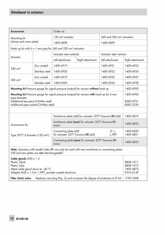
Accessories Order no.
Mounting kit(clamp and cover plate)
120 cm² actuator 240 and 350 cm² actuators
1400-6898 1400-6899
Hook-up kit with 6 x 1 mm pipe for 240 and 350 cm² actuators
ActuatorActuator stem extends Actuator stem retracts
Left attachment Right attachment Left attachment Right attachment
240 cm²Zinc coated 1400-6919 1400-6921 1400-6923
Stainless steel 1400-6920 1400-6922 1400-6924
350 cm²Zinc coated 1400-6919 1400-6925 1400-6927
Stainless steel 1400-6920 1400-6926 1400-6928
Mounting kit Pressure gauge for signal pressure (output) for version without hook-up 1400-6900
Mounting kit Pressure gauge for signal pressure (output) for version with hook-up for 6 mmpipe diameterAdditional tee piece (CrNiMo steel)Additional pipe socket (CrNiMo steel)
1400-6900
8582-07218582-3330
Accessories for
Type 3277-5 Actuator (120 cm²)
Switchover plate (old) for actuator 3277-5xxxxxx.00 (old) 1400-6819
Switchover plate (new) for actuator 3277-5xxxxxx.01(new) 1400-6822
Connecting plate (old) G 18
for actuator 3277-5xxxxxx.00 (old) 18 NPT
1400-68201400-6821
Connecting plate (new) for actuator 3277-5xxxxxx.01(new) 1400-6823
Note: Actuators with model index 01 can only be used with new switchover or connecting plates.Old and new plates are not interchangeable!
Cable glands M20 x 1.5Plastic, blackPlastic, blueMetal cable gland down to –40 °CAdapter M20 x 1.5 to 1
2 NPT, powder-coated aluminum
8808-10118808-10121890-48750310-2149
Filter check valve Replaces vent plug (Fig. 2) and increases the degree of protection to IP 65 1790-7408

3 Connections
3.1 Pneumatic connections
The pneumatic connections are designed as18-18 NPT or ISO 228/1-G 1
8 tapped holes.The supply input (SUPPLY 9) is fitted with afilter to clean impure air. The filter is fixedon a support and can be removed using ascrewdriver for cleaning or replacement, ifnecessary (filter order no. 1400-6897).
The customary male fittings for metal andcopper pipes or plastic hoses can be used.
Note: The supply air must be dry and free ofoil and dust.Observe maintenance instructions of up-stream pressure reducing stations.Thoroughly blow out all air lines before con-nection.
3.1.1 Signal pressure indication
To precisely adjust the positioner, we recom-mend attaching a pressure gauge to thepositioner to measure the signal pressure(OUTPUT 36).
The attachment kit is listed in the accessoriestable on page 12.
3.1.2 Supply pressure
The required supply pressure depends onthe bench range and the direction of action(fail-safe action) of the actuator.
The bench range is indicated as springrange or signal pressure range on the
nameplate; the direction of action is speci-fied by a symbol.
Actuator stem extends:Fail-safe action "valve CLOSED"(with globe and angle valves)
Required supply pressure = upper benchrange value + 0.2 bar, at least 1.4 bar.
Actuator stem retracts:Fail-safe action "valve OPEN"(with globe and angle valves)
The required supply pressure for tight-clos-ing valves is roughly calculated from theequation for the maximum signal pressurepstmax:
pstmax = F + d p
4 A
2�� � �
�bar
d = seat diameter [cm]�p = differential pressure at the valve [bar]A = effective diaphragm area [cm²]F = upper bench range value of the
actuator
If no values are specified, calculate as fol-lows:
Required supply pressure = upper benchrange value + 1 bar
3.1.3 Degree of protection IP 65
To increase the degree of protection fromIP 54 to IP 65, replace the vent plug on theactuator casing with the filter check valve(accessories). For details, see Fig. 2.
EB 8385 EN 13
Connections

3.2 Electrical connections
For electrical installation, observe therelevant electrotechnical regulationsand the accident prevention regula-tions that apply in the country of use.
The following regulations apply to mountingand installation in hazardous areas:EN 60079-14: 2008 Explosive atmo-spheres – Part 14: Electrical installationsdesign, selection and erection (orVDE 0165 Part 1).
CAUTION!– Adhere to the terminal assignment!– Switching the assignment of the electrical
terminals may cause the explosion pro-tection to become ineffective!
– Do not loosen enameled screws in or onthe housing.
– The maximum permissible values speci-fied in the national EC type examinationcertificates apply when interconnectingintrinsically safe electrical equipment (Uior Uo; Ii or Io; Pi or Po; Ci or Co, and Li orLo).
Selecting cables and wires:
Observe Clause 12 of EN 60079-14: 2008(VDE 0165 Part 1) when installing intrinsi-cally safe circuits. The Subclause 12.2.2.7applies when running multi-core cables con-taining more than one intrinsically safe cir-cuit.
In particular, the radial thickness of the con-ductor insulation for common insulation ma-terials, such as polyethylene, must have aminimum radial thickness of 0.2 mm.
The diameter of an individual wire in afine-stranded conductor must not be smallerthan 0.1 mm. Protect the conductor endsagainst splicing, e.g. by using wire-end fer-rules.
When two separate cables are used for con-nection, an additional cable gland can beinstalled.
Seal cable entries left unused with plugs.
Devices used at ambient temperatures be-low –20 °C must be fitted with metal cableglands.
14 EB 8385 EN
Connections
+ – + –+11 –12
1
2
3
4
Fig. 5 · Terminal connections
Conn-ector Terminal
12
+11–11 i/p converter
34
+– Limit switch
Switching amplifierEN 60947-5-6
Limit switchPneumatic version
Control signamA
Limit switchElectropneumatic version
Switching amplifierEN 60947-5-6
Connection withconnector
(DIN 43650)

Equipment for use in zone 2/zone 22
In equipment operated with type of protec-tion Ex nA II (non-sparking equipment) ac-cording to EN 60079-15: 2003, circuitsmay be connected, interrupted or switchedwhile energized only during installation,maintenance or repair.
Cable entries
For electropneumatic positioner versions,connect the reference variable lines to theterminals +11 and –12 using the cablegland.
Versions with limit switch require their elec-tric lines to be connected to the terminals +and –.
Cable glands are available as accessories.For details, see table on page 12.
3.2.1 Switching amplifier
For operation of the inductive limit switch, aswitching amplifier must be connected in theoutput circuit. For installation in hazardousareas, observe the relevant regulations.
4 Operation – Adjustment
4.1 Starting point and referencevariable
The built-in range spring of the positioner isassigned to the rated valve travel and the in-put signal (reference variable), as specifiedin the range spring table on page 11.
Normally, the reference variable span is100 % = 0.8 bar or 16 mA.
A smaller span of, for example, 50 % =0.4 bar or 8 mA is only required forsplit-range operation (Fig. 6).
The span can be changed by replacing therange spring.
When making adjustments on the positioner,the travel must be adapted to the input sig-nal (reference variable) and vice versa.
With an input signal of, for example, 0.2 to1 bar or 4 to 20 mA, the valve must travelthrough its full range, i.e. from 0 to 100 %.
EB 8385 EN 15
Operation – Adjustment
100%
0%0.2 1 bar4 20 mA
0.2 1 bar4 20
0.612 mA
<> << <> <<
100%
0%
Fig. 6 · Normal and split-range operationDead band
Reference variableInput signal
Valve 1 Valve 2
Open
Travel
Closed
Open
Travel
Closed

The starting point (zero) in this case is 0.2bar or 4 mA, the upper range value is 1 baror 20 mA.
In split-range operation, the controller outputsignal intended to actuate two control valvesis split into half to allow each valve to passthrough its entire travel range at one half ofthe signal range (e.g. first valve adjusted to0.2 to 0.6 bar or 4 to 12 mA, and the sec-ond valve adjusted to 0.6 to 1 bar or 12 to20 mA).
To avoid any crossing-over, allow for adead band of � 0.05 bar or � 0.5 mA asshown in Fig. 6.
The starting point (zero) is adjusted at theZERO adjustment screw (5). The referencevariable span, and thus the upper rangevalue is adjusted at the SPAN adjustmentscrew (8).
� In a pneumatic positioner, connect an airsource providing max. 1.5 bar to thepositioner input (IN SIGNAL 27) via aremote adjuster and a pressure gauge.
� In an electropneumatic positioner, con-nect an ammeter to the terminals +11and –12.
� Connect compressed air to the supply in-put (SUPPLY 9); also see section 3.1.2.
4.2 Adjustment for actuator withfail-safe action "Actuatorstem extends"
NOTICETo ensure that the full closing force can beeffective at the control valve, the diaphragmchamber must be completely vented whenreaching the lower range value (direction ofaction >>) or the upper range value (direc-tion of action <> ) of the reference variable.
Therefore, set the input signal to a slightlyincreased starting point of approx. 0.23 bar(4.5 mA) when the direction of action is di-rect >>, and to a slightly lowered startingpoint of 0.97 bar (19.5 mA) when the direc-tion of action is reverse <>.
This applies in particular to controllers andcontrol systems whose output signal is lim-ited to a range of 4 to 20 mA.
Starting point (zero)e.g. 0.23 bar (4.5 mA)
1. Turn ZERO adjustment screw (5) untilthe plug stem just begins to move fromits resting position (observe plug stem atthe travel indicator).
2. Decrease input signal and increaseagain slowly. Check whether the plugstem starts moving at a starting point of0.23 bar (4.5 mA) and correct it, if nec-essary.
16 EB 8385 EN
Operation – Adjustment

Upper range value (travel)e.g. 1 bar (20 mA)
3. After the starting point has been ad-justed, increase input signal.
The plug stem must stand still at an up-per range value of exactly 1 bar(20 mA). It must have passed through100 % travel (observe the travel indica-tor on the valve!). If the upper rangevalue does not correlate, correct it byadjusting the SPAN adjustment screw(8).Turning the screw towards the fulcrum ofthe lever increases the travel, whereasturning it away reduces the travel.
Note: Make sure that the range spring (7) isin the upright position for adjustment. If nec-essary, hook the spring at another point onthe lever (6).
NOTICEIf you change the span, the zero point mustbe readjusted as well.
4. Check upper range value again.Readjust both values until they are cor-rect.
4.3 Adjustment for actuator withfail-safe action "Actuatorstem retracts"
NOTICEFor actuator version "Actuator stem re-tracts", the diaphragm chamber must beloaded with a pressure that is sufficient totightly close the valve, even when upstreampressure of the plant prevails.The upper range value of the reference vari-able must be 1 bar or 20 mA (direct direc-tion of action >>) and the lower input rangevalue must be 0.2 bar or 4 mA (reverse di-rection of action <>).
The required signal pressure is roughly cal-culated in the same way as the requiredsupply pressure according to the equation insection 3.1.2 on page 13.
Starting point (zero)e.g. 1 bar (20 mA)
1. Adjust input signal to 1 bar (20 mA) us-ing the remote adjuster (ammeter).
2. Turn ZERO adjustment screw (5) untilthe plug stem just starts to move from itsinitial position.
3. Increase input signal and slowly reduceit to 1 bar (20 mA). Check if the plugstem begins to move at exactly 1 bar(20 mA).
4. Correct any deviations using the ZEROadjustment screw (5).
EB 8385 EN 17
Operation – Adjustment

18 EB 8385 EN
Operation – Adjustment
Upper range value (travel)e.g. 0.2 bar (4 mA)
5. After the starting point has been ad-justed, set the input signal to 0.2 bar(4 mA) at the remote adjuster (amme-ter). The plug stem must stand still at anupper range value of exactly 0.2 bar(4 mA). It must have passed through100 % travel (observe the travel indica-tor on the valve!).
6. If the upper range value does not corre-late, correct it using the SPAN adjust-ment screw (8).Turning the screw towards the fulcrum ofthe lever increases the travel, whereasturning it away reduces the travel.
NOTICEIf you change the span, the zero point mustbe readjusted as well.
7. Check upper range value again. Read-just both values until they are correct.
8. When you have completed the correc-tion work, adjust input signal to 1 bar(20 mA) again.
9. Turn ZERO adjustment screw (5) againuntil the required signal pressure (sec-tion 3.1.2 on page 13) is indicated on apressure gauge installed in the signalpressure line.
If no pressure gauge is available, adjustthe starting point to 0.97 bar(19.5 mA).
NOTICEAfter adjusting the positioner, close the actu-ator yoke with the cover plate.Make sure that the vent plug in the coverplate is directed downwards when the con-trol valve is installed in the plant to preventcondensed water from collecting in thepositioner.

5 Adjusting the limit switch
The positioner version 3760-X1XXXX isequipped with an inductive limit switch tosignal, for example, a travel end position.
The travel of the plug stem is transmitted tothe metal tag of the proximity switch overthe pin (5) and lever (3).
For operation of the inductive limit switch, aswitching amplifier (section 3.2.1) must beconnected to the output circuit.
Normally, the limit switch is adjusted to pro-vide a signal when the valve has reachedone of its end positions. However, you mayalso adjust to signal intermediate travel po-sitions.
Adjusting the switching point:
Prior to adjusting the limit switch, the start-ing point and upper range value of thepositioner need to be adjusted.
1. The yellow switching point indicator (7)must be within the area of the notchmark (6). If this is not the case, turn ad-justment screw (4).
2. Move control valve to the desiredswitching position. Turn adjustmentscrew (4) until the switching point isreached. This will be indicated by theswitching amplifier.
The switching element and the levers re-quired to operate it are slightly sensitive totemperature changes. To ensure reliableswitching, both the switching hysteresis andthe displacement of the switching point dueto temperature fluctuations need to be takeninto account when adjusting the positioner.
The terminal used to connect the limit switch(41/42 or 51/52) can be written on the ad-hesive function label inside the positionercover.
Mark the adjusted switching function, i.e.switching at either open or closed valve onthe other label.
EB 8385 EN 19
Adjusting the limit switch

5.1 Retrofitting a limit switch
For installation of a limit switch in an i/ppositioner (model index .02 and higher;model index .00 and .01 without explosionprotection) at a later date, a retrofit kit (or-der no. 1400-8803) is required.
To retrofit the limit switch, the positionermust be removed from the actuator.
1. Connect the plug of the proximity switchcable to the plug connection (2) locatedon the PCB.
2. Install support plate (8) on the aluminumplate adjacent to the terminal base usingtwo screws.
3. Attach positioner to the actuator.
4. Fix bracket with pin (5) on the clamp at-tached to the actuator stem and secure itwith screws. Make sure that the pin (5)is located in the recess of the operatinglever (3).
5. Connect the switching amplifier to theterminals + and – using cable glands orconnectors.
6. Refer to section 5 for adjustment.
20 EB 8385 EN
Adjusting the limit switch
1
2
3
4
7
56
8
Fig. 7 · Limit switch, for positioner with left attachment (for right attachment, drawing turned by 180°)
1 Terminal base with PCB2 Connector3 Operating lever4 Adjustment screw5 Pin6 Notch mark7 Switching point indicator8 Support plate
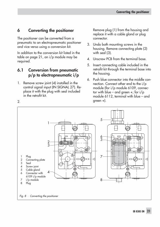
6 Converting the positioner
The positioner can be converted from apneumatic to an electropneumatic positionerand vice versa using a conversion kit.
In addition to the conversion kit listed in thetable on page 21, an i/p module may berequired.
6.1 Conversion from pneumaticp/p to electropneumatic i/p
1. Remove screw joint (4) installed in thecontrol signal input (IN SIGNAL 27). Re-place it with the plug with seal includedin the retrofit kit.
2.
Remove plug (1) from the housing andreplace it with a cable gland or plugconnector.
3. Undo both mounting screws in thehousing. Remove connecting plate (2)with seal (3).
4. Unscrew PCB from the terminal base.
5. Insert connecting cable included in theretrofit kit through the terminal base intothe housing.
6. Push blue connector into the middle con-nection. Connect other end to the i/pmodule (for i/p module 6109, connec-tor with blue – and green +; for i/pmodule 6112, terminal with blue – andgreen +).
EB 8385 EN 21
Converting the positioner
1
23
4
5
63
7
8
Fig. 8 · Converting the positioner
1 Plug2 Connecting plate3 Seal4 Screw joint5 Cable gland6 Connector with
6109 i/p module7 i/p module8 Plug

7. Fasten i/p module in the housing usingthe two screws. Make sure that the seal(3) with the restriction is properly posi-tioned in the module. The restrictionmust be located over the right bore holeof the housing (looking from above), seeFig. 8.
6.2 Conversion from electrop-neumatic i/p to pneumaticp/p
1. Remove plug (8) with seal installed inthe control signal input (IN SIGNAL 27).Replace it with an appropriate screwgland (5) with G 1
8 or 18 NPT thread.
2. Remove mounting screws. After discon-necting the electrical connections, takei/p module (7) out of the housing.
3. Seal holes in the bottom of the housingusing the connecting plate (2) contain-ing the seal (3). Make sure that the plateis installed in the correct position (seeFig. 8).
4. Unscrew PCB from the terminal base.Remove blue connector and pull out theconnecting cable.
5. Reinstall PCB on the terminal base usingscrews.
22 EB 8385 EN
Conversion and retrofit kits Order numbers
Pneumatic to electropneumatic conversion(model index 01 or higher) With Type 6109 i/p module 1)
Without limit switch Order no. 1400-69884 to 20 mA without explosion protection 6109-0010
With limit switch Order no. 1400-6904
Pneumatic to electropneumatic conversion(model index 01 or higher) With Type 6112 i/p module 1)
Without limit switch Order no. 1400-69894 to 20 mA without explosion protection 6112-041110
or
With limit switch Order no. 1400-6906 0 to 20 mA without explosion protection 6112-042110
Electropneumatic to pneumatic conversion 1400-6931
Retrofitting electrical connection with connectoracc. to DIN EN 175301 - AF3-Pg 11 1400-6902
1) The required i/p module with the model number written in bold must be ordered separately. It is not includedin the conversion kit.
Converting the positioner

7 Dimensions in mm
Dimensions in mm
EB 8385 EN 23
110 29 121
1735
OUTPUT36
38
Ø40
SUPPLY
IN. SIG
NA
L
279
8436
128
48
M20 x 1.5
Pressure gaugefor signal pressure
Connector acc. toDIN 43650
Pneumatic connectionsG 1
8 or 18 NPT

24 EB 8385 EN

EB 8385 EN 25
26 EB 8385 EN

EB 8385 EN 27

28 EB 8385 EN

EB 8385 EN 29

30 EB 8385 EN

EB 8385 EN 31

32 EB 8385 EN

EB 8385 EN 33

34 EB 8385 EN

EB 8385 EN 35

SAMSON AG · MESS- UND REGELTECHNIKWeismüllerstraße 3 · 60314 Frankfurt am Main · GermanyPhone: +49 69 4009-0 · Fax: +49 69 4009-1507Internet: http://www.samson.de EB 8385 EN 20
12-0
7
![[ZH] Î · instructions as well as warning and caution notes in the mounting and operating instructions. 1 Mounting Direct attachment to SAMSON Type 3277 Actuator Travel [mm] Actuator](https://static.documents.pub/doc/80x56/5e82ffb090f143456c61acb9/zh-instructions-as-well-as-warning-and-caution-notes-in-the-mounting-and-operating.jpg)


