80
Translation of original instructions EB 8394 EN Firmware version 1.12 Mounting and Operating Instructions Edition June 2014 Series 3725 Type 3725 Electropneumatic Positioner

Translation of original instructions
EB 8394 EN
Firmware version 1.12
Mounting and Operating Instructions
Edition June 2014
Series 3725Type 3725 Electropneumatic Positioner
Note on these mounting and operating instructions
These mounting and operating instructions assist you in mounting and operating the device safely. The instructions are binding for handling SAMSON devices.
Î For the safe and proper use of these instructions, read them carefully and keep them for later reference.
Î If you have any questions about these instructions, contact SAMSON‘s After-sales Service Department ([email protected]).
The mounting and operating instructions for the devices are included in the scope of delivery. The latest documentation is available on our website at www.samson.de > Service & Support > Downloads > Documentation.
Definition of signal words
Hazardous situations which, if not avoided, will result in death or serious injury
Hazardous situations which, if not avoided, could result in death or serious injury
Property damage message or malfunction
Additional information
Recommended action
DANGER!
WARNING!
NOTICE!
Note
Tip
2 EB 8394 EN

Contents
EB 8394 EN 3
1 Safety instructions and measures ...................................................................61.1 Notes on possible severe personal injury .........................................................91.2 Notes on possible personal injury .................................................................101.3 Notes on possible property damage ..............................................................102 Markings on the device ...............................................................................122.1 Nameplate ..................................................................................................122.2 Article code .................................................................................................133 Design and principle of operation ................................................................143.1 Mounting versions ........................................................................................143.2 Accessories and mounting parts ....................................................................163.3 Travel tables ................................................................................................203.4 Technical data .............................................................................................213.5 Dimensions in mm ........................................................................................234 Measures for preparation ............................................................................254.1 Unpacking ..................................................................................................254.2 Transporting and lifting ................................................................................254.2.1 Transporting ................................................................................................254.2.2 Lifting ..........................................................................................................254.3 Storage .......................................................................................................255 Mounting and start-up .................................................................................265.1 Lever and pin position ..................................................................................265.2 Direct attachment .........................................................................................285.2.1 Type3277-5andType 2780-2Actuators ......................................................285.2.2 Type 3277Actuator .....................................................................................325.3 AttachmentaccordingtoIEC 60534-6 ...........................................................345.4 AttachmenttoType 3372Actuator(V2001) ...................................................365.5 Attachment to rotary actuators ......................................................................385.5.1 Heavy-duty version ......................................................................................405.5.2 MountingtheType 3710ReversingAmplifier .................................................425.6 Pneumatic connections..................................................................................435.7 Connecting the supply air .............................................................................435.7.1 Signal pressure connection ...........................................................................435.7.2 Supply pressure ...........................................................................................445.8 Electrical connections ...................................................................................455.8.1 Electric power supply ...................................................................................465.8.2 Cable entry .................................................................................................465.8.3 Connecting the electrical power ....................................................................46

Contents
4 EB 8394 EN
6 Operation ...................................................................................................486.1 Operating controls .......................................................................................486.1.1 Capacitive keys ............................................................................................486.1.2 VolumerestrictionQ .....................................................................................486.1.3 Display .......................................................................................................497 Operating the positioner ..............................................................................507.1 Adapting the display ....................................................................................517.2 Enablingconfigurationtochangeparameters.................................................517.3 AdjustingthevolumerestrictionQ .................................................................527.4 Entering the air action ..................................................................................537.5 Entering the direction of action ......................................................................537.6 Limiting the signal pressure ...........................................................................547.7 Setting other parameters ...............................................................................557.8 Initialization ................................................................................................557.8.1 Canceling initialization .................................................................................567.9 Zero calibration ...........................................................................................577.9.1 Canceling zero calibration ............................................................................587.10 Manual mode ..............................................................................................587.11 Reset ...........................................................................................................598 Servicing.....................................................................................................608.1 Cleaning the window in the cover..................................................................608.2 Preparation for return shipment .....................................................................609 Malfunctions ...............................................................................................619.1 Resettingerrorcodes ....................................................................................629.2 Error codes ..................................................................................................649.3 Emergency action ........................................................................................6510 Decommissioning and disassembly ..............................................................6610.1 Decommissioning .........................................................................................6610.2 Removingthepositioner ...............................................................................6610.3 Disposal ......................................................................................................6611 Annex.........................................................................................................6711.1 After-sales service ........................................................................................6711.2 Code list ......................................................................................................6811.2.1 Parameter codes ..........................................................................................68

Contents
EB 8394 EN 5
Firmware revisions
1.02 (old) 1.03 (new)
Internal revisions
1.03 (old) 1.10 (new)
Settingofthetravelinstepsof0.5 mm(P4parametercode)
Monitoring of the end stops only during initialization and in manual mode
To suppress common-mode interference on the signal lines, the D component of the positioner is switched off when the actuator is at a standstill.
1.10 (old) 1.11 (new)
Internal revisions
1.11 (old) 1.12 (current version)
Internal revisions
6 EB 8394 EN
Safety instructions and measures
1 Safety instructions and measuresIntended useTheSAMSONType 3725Positionerismountedonpneumaticcontrolvalvesandisusedtoassign the valve position to the control signal. The device is designed to operate under exact-lydefinedconditions(e.g.operatingpressure,temperature).Therefore,operatorsmusten-sure that the positioner is only used in applications where the operating conditions corre-spond to the technical data. In case operators intend to use the positioner in other applica-tionsorconditionsthanspecified,contactSAMSON.SAMSON does not assume any liability for damage resulting from the failure to use the de-vice for its intended purpose or for damage caused by external forces or any other external factors.
Î Refertothetechnicaldataforlimitsandfieldsofapplicationaswellaspossibleuses.
Reasonably foreseeable misuseTheType 3725Positionerisnot suitable for the following applications: − Useoutsidethelimitsdefinedduringsizingandinthetechnicaldata
Furthermore, the following activities do not comply with the intended use: − Use of non-original spare parts − PerformingmaintenanceactivitiesnotspecifiedbySAMSON
Qualifications of operating personnelThepositionermustbemounted,startedup,andservicedbyfullytrainedandqualifiedper-sonnel only; the accepted industry codes and practices are to be observed. According to these mounting and operating instructions, trained personnel refers to individuals who are able to judge the work they are assigned to and recognize possible hazards due to their spe-cialized training, their knowledge and experience as well as their knowledge of the applica-ble standards.Explosion-protected versions of this device are to be operated only by personnel who has un-dergone special training or instructions or who is authorized to work on explosion-protected devices in hazardous areas.
EB 8394 EN 7
Safety instructions and measures
Personal protective equipmentNo personal protective equipment is required for the direct handling of the positioner. Work on the control valve may be necessary when mounting or removing the positioner.
Î Observetherequirementsforpersonalprotectiveequipmentspecifiedinthevalvedocu-mentation.
Î Check with the plant operator for details on further protective equipment.
Revisions and other modificationsRevisions,conversionsorothermodificationstotheproductarenotauthorizedbySAMSON.They are performed at the user's own risk and may lead to safety hazards, for example. Fur-thermore, the product may no longer meet the requirements for its intended use.
Safety featuresUpon failure of the air supply or electric signal, the positioner vents the actuator, causing valve to move to the fail-safe position determined by the actuator.
Warning against residual hazardsThepositionerhasdirectinfluenceonthecontrolvalve.Toavoidpersonalinjuryorpropertydamage, plant operators and operating personnel must prevent hazards that could be caused in the control valve by the process medium, the operating pressure, the signal pres-sure or by moving parts by taking appropriate precautions. They must observe all hazard statements, warning and caution notes in these mounting and operating instructions, espe-cially for installation, start-up, and service work.If inadmissible motions or forces are produced in the pneumatic actuator as a result of the supply pressure level, it must be restricted using a suitable supply pressure reducing station.
Responsibilities of the operatorThe operator is responsible for proper operation and compliance with the safety regulations. Operators are obliged to provide these mounting and operating instructions to the operating personnel and to instruct them in proper operation. Furthermore, the operator must ensure that operating personnel or third persons are not exposed to any danger.
Responsibilities of operating personnelOperating personnel must read and understand these mounting and operating instructions as wellasthespecifiedhazardstatements,warningandcautionnotes.Furthermore,theoperat-ing personnel must be familiar with the applicable health, safety and accident prevention regulations and comply with them.

8 EB 8394 EN
Safety instructions and measures
Servicing explosion-protected devicesIf a part of the device on which the explosion protection is based needs to be serviced, the devicemustnotbeputbackintooperationuntilaqualifiedinspectorhasassesseditaccord-ingtoexplosionprotectionrequirements,hasissuedaninspectioncertificate,orgiventhedeviceamarkofconformity.Inspectionbyaqualifiedinspectorisnotrequiredifthemanu-facturer performs a routine test on the device before putting it back into operation. Document thepassingoftheroutinetestbyattachingamarkofconformitytothedevice.Replaceex-plosion-protected components only with original, routine-tested components by the manufac-turer.Devices that have already been operated outside hazardous areas and are intended for fu-ture use inside hazardous areas must comply with the safety requirements placed on serviced devices. Before being operated inside hazardous areas, test the devices according to the specificationsforservicingexplosion-protecteddevices.
Maintenance, calibration, and work on equipment Î Only use intrinsically safe current/voltage calibrators and measuring instruments for in-terconnection with intrinsically safe circuits to check or calibrate the equipment inside or outside hazardous areas.
Î Observethemaximumpermissiblevaluesspecifiedinthecertificatesforintrinsicallysafecircuits.
Referenced standards and regulationsDeviceswithaCEmarkingfulfilltherequirementsoftheDirectives2014/34/EUand2014/30/EU. The declaration of conformity is included at the end of these instructions.
Referenced documentationThe following documents apply in addition to these mounting and operating instructions: − The mounting and operating instructions of the components on which the positioner is
mounted (valve, actuator, valve accessories, etc.).

EB 8394 EN 9
Safety instructions and measures
1.1 Notes on possible severe personal injury
DANGER!
Risk of the formation of an explosive atmosphere.
Incorrect installation, operation, or maintenance of the positioner in potentially explosive atmospheres may lead to ignition of the atmosphere and cause death.
Î Thefollowingregulationsapplytoinstallationinhazardousareas:EN 60079-14(VDE 0165,Part 1).
Î Installation, operation, or maintenance of the positioner must only performed by personnel who has undergone special training or instructions or who is authorized to work on explosion-protected devices in hazardous areas.

10 EB 8394 EN
Safety instructions and measures
1.2 Notes on possible personal injury
WARNING!
Risk of personal injury due to moving parts on the valve.During initialization of the positioner and during operation, the actuator stem moves throughitsentiretravelrange.Injurytohandsorfingersispossibleiftheyareinsertedinto the valve.
Î Duringinitialization,donotinserthandsorfingersintothevalveyokeanddonottouch any moving valve parts.
1.3 Notes on possible property damage
NOTICE!
Risk of damage to the positioner due to incorrect mounting position. Î Do not mount the positioner with the back of the device/vent opening facing upward. Î Do not seal the vent opening when the device is installed on site.
Risk of malfunction due to incorrect sequence during start-up.The positioner can only work properly if the mounting and start-up are performed in the prescribed sequence.
Î Performmountingandstart-upasdescribedinsection 5inpage 26.
An incorrect electric signal will damage the positioner.A current source must be used to provide the electrical power for the positioner.
Î Only use a current source and never a voltage source.
Incorrect assignment of the terminals will damage the positioner and will lead to mal-function.For the positioner to function properly, the prescribed terminal assignment must be ob-served.
Î Connect the electrical wiring to the positioner according to the prescribed terminal assignment.

EB 8394 EN 11
Safety instructions and measures
Malfunction due to initialization not yet completed.The initialization causes the positioner to be adapted to the mounting situation. After ini-tialization is completed, the positioner is ready to use.
Î Initializethepositioneronthefirststart-up. Î Re-initializepositionerafterchangingthemountingposition.
Risk of positioner damage due to incorrect grounding of the electric welding equipment.
Î Do not ground electric welding equipment near to the positioner.
Incorrect cleaning will damage the window.The window is made of Makrolon® and will be damaged when cleaned with abrasive cleaning agents or agents containing solvents.
Î Do not rub the window dry. Î Do not use any cleaning agents containing chlorine or alcohol or abrasive cleaning agents.
Î Use a non-abrasive, soft cloth for cleaning.

12 EB 8394 EN
Markings on the device
2 Markings on the device
2.1 Nameplate
SAMSON 3725
Supply max. 10 bar / 150 psiInput 4 ... 20 mA DC
See technical data for ambient temperature -40 °C £ Ta* £+80 °C
Positioner
SAMSON AG D-60314 Frankfurt Made in Germany
Firmware Model 3725 - 110Var.-ID Serial no.
2
4
5
7 86
1
3
1 Max. supply pressure2 Signal range3 Type of protection for explosion-protected devices4 Temperaturelimitsinthetestcertificatesfortheexplosion-protecteddevices5 Firmware version6 Model no.7 ConfigurationID8 Serial number

EB 8394 EN 13
Markings on the device
2.2 Article codePositioner Type 3725- x x x 0 0 0 0 x 0 0WithLCDandautotune,4to20 mAreferencevariable
Explosion protection 1)
Without 0 0 0
Intrinsic safety: ATEX 1 1 0 0
Intrinsic safety: STCC 1 1 0 0
Intrinsic safety: CSA 1 3 0 0
Intrinsic safety: GOST 1 1 3 0
Shipbuildingcertificate
Without 0
BureauVeritascertification 1
1) SeeTable 1fordetailsonexplosionprotectioncertificates.
Table 1: Summary of explosion protection certificates
Type Certification Type of protection
3725-1100
STCC On request
Number PTB 11 ATEX 2020 X
II 2 G Ex ia IIC T4Date 2011-08-25EC type examina-tioncertificate
3725-113
Number RUC-DE.GB08.B.00697
1Ex ia IIC T4 Gb XDate 2014-12-15
Validuntil 2019-12-14
3725-130 CSANumber 2703735 X Ex ia IIC T4;
Class I, Zone 0, AEx ia IIC T4;Class I, Div. 1, Groups A, B, C, DDate 2014-06-03

14 EB 8394 EN
Design and principle of operation
3 Design and principle of oper-ation
TheType 3725ElectropneumaticPositionerismounted on pneumatic control valves and is used to assign the valve position (controlled variable x)tothecontrolsignal(referencevariable w).Thepositionercomparestheelectric control signal of a control system to the travel or opening angle of the control valve and issues a signal pressure (output variable y)forthepneumaticactuator.The positioner mainly consists of the follow-ingcomponents(seeFig. 1): − Magnetoresistive sensor (2) − Analog i/p converter (6) with a down-
stream air capacity booster (7) − Electronics unit with microcontroller (4)
The travel or opening angle is measured by the pick-up lever, non-contact magnetoresis-tive sensor and downstream electronics.The pick-up lever is connected to a magnet inside the device. The motion of the pick-up lever causes the direction of the magnetic fieldtochange.Thischangeissensedbythesensor. The electronics unit determines the current position of the actuator stem or open-ing angle from this information.The position of the actuator stem or opening angle is transmitted to the microcontroller (3) over the A/D converter (4). The PD control algorithm in the microprocessor compares thisactualpositiontothe4to20 mAcontrolsignal after it has been converted by the A/D converter (3). In case of a system devi-
ation, the activation of the i/p module (6) is changed so that the actuator of the valve (1) is pressurized or vented accordingly over the downstream booster (7). The supply air is supplied to the booster and the pressure reg-ulator (8).The output signal pressure supplied by the boostercanbelimitedto2.3 barbysoft-ware.ThevolumerestrictionQ(10)isusedtoopti-mize the positioner by adapting it to the ac-tuator.
Tight-closing functionThepneumaticactuatoriscompletelyfilledwith air or vented as soon as the reference variablefallsbelow1 %orexceeds99 %(see end positions set in P10 and P11 pa-rameter codes).
3.1 Mounting versionsTheType 3725Positionerissuitableforthefollowing types of attachment: − Direct attachment to SAMSON Type 3277andType 2780-2Actuators
− Attachment to actuators according to IEC 60534-6(NAMUR)
− AttachmenttoType 3372Actuator(Se-riesV2001Valves)
− Attachment to rotary actuators according toVDI/VDE 3845
Î Refertosection 5.2onwardsforade-scription of the types of attachment.

EB 8394 EN 15
Design and principle of operation
%
Smm
%mm
Q
3 4
11
6
7
8 10
1
w
9
xy
2
5
1 Valve 7 Air capacity booster2 Sensor 8 Pressure regulator3 A/D converter 9 Fixed restriction4 Microcontroller 10 Volumerestriction5 D/A converter 11 Display6 i/p converter
Fig. 1: Circuit diagram

16 EB 8394 EN
Design and principle of operation
3.2 Accessories and mounting parts
Table 2: Direct attachment to Type 3277-5 and Type 2780-2 Actuators (see sec-tion 5.2)
Order no.
Mounting parts
Foractuatorsupto120 cm² 1402-0239
Accessories for actuator
Switchover plate for Type 3277-5xxxxxx.01 Actuator 1400-6822
Connecting plate for additional attachment of, e.g. a solenoid valve: G 1/8 1400-6823
Accessories for positioner
Connecting plate (6)G ¼ 1402-0235
¼NPT 1402-0236
Pressure gauge bracket (7)G ¼ 1402-0237
¼NPT 1402-0238
PressuregaugebracketforcombinationwithType 4708-55SupplyPressureRegulator 1402-1515
Pressuregaugemountingkit(8)uptomax.6 bar(output/supply)
Stainless steel/brass 1400-6950
Stainless steel/ stainless steel 1400-6951
Table 3: Direct attachment to Type 3277 (section 5.2.2) Order no.
Mounting parts
Actuators240,350,355,700 cm² 1402-0240
Accessories
Connection block with seals and screwG ¼ 1402-0241
¼ NPT 1402-0242
Pressuregaugemountingkituptomax.6 bar(output/supply)
Stainless steel/brass 1400-6950
Stainless steel/ stainless steel 1400-6951
EB 8394 EN 17
Design and principle of operation
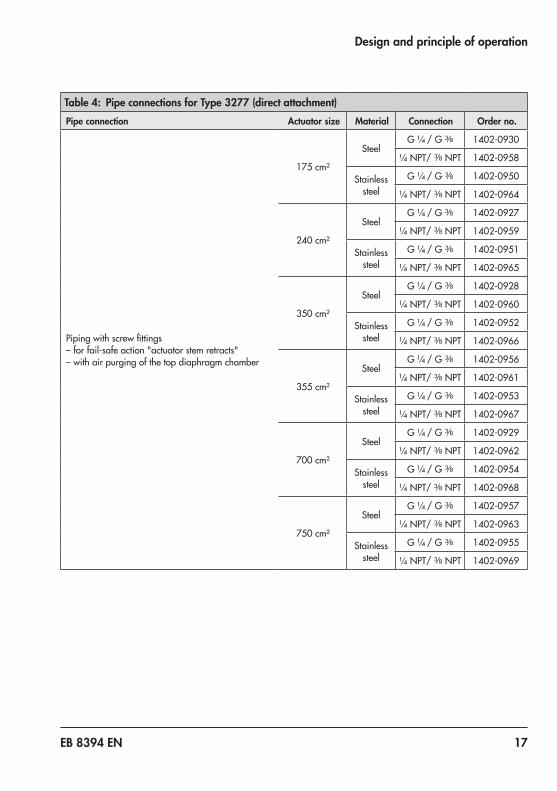
Table 4: Pipe connections for Type 3277 (direct attachment)Pipe connection Actuator size Material Connection Order no.
Pipingwithscrewfittings– for fail-safe action "actuator stem retracts"– with air purging of the top diaphragm chamber
175 cm²
SteelG ¼ /G 3/8 1402-0930
¼ NPT/3/8 NPT 1402-0958
Stainless steel
G ¼ /G 3/8 1402-0950
¼ NPT/3/8 NPT 1402-0964
240 cm²
SteelG ¼ /G 3/8 1402-0927
¼ NPT/3/8 NPT 1402-0959
Stainless steel
G ¼ /G 3/8 1402-0951
¼ NPT/3/8 NPT 1402-0965
350 cm²
SteelG ¼ /G 3/8 1402-0928
¼ NPT/3/8 NPT 1402-0960
Stainless steel
G ¼ /G 3/8 1402-0952
¼ NPT/3/8 NPT 1402-0966
355 cm²
SteelG ¼ /G 3/8 1402-0956
¼ NPT/3/8 NPT 1402-0961
Stainless steel
G ¼ /G 3/8 1402-0953
¼ NPT/3/8 NPT 1402-0967
700 cm²
SteelG ¼ /G 3/8 1402-0929
¼ NPT/3/8 NPT 1402-0962
Stainless steel
G ¼ /G 3/8 1402-0954
¼ NPT/3/8 NPT 1402-0968
750 cm²
SteelG ¼ /G 3/8 1402-0957
¼ NPT/3/8 NPT 1402-0963
Stainless steel
G ¼ /G 3/8 1402-0955
¼ NPT/3/8 NPT 1402-0969

18 EB 8394 EN
Design and principle of operation
Table 5: Attachment to NAMUR rib or attachment to rod-type yokes according to IEC 60534-6 (section 5.3)
Order no.
5 to 50 mm travel, lever already on positioner
For actuators1402-0330ActuatorsfromothermanufacturersandType 3271with120to700cm²effective
areas
Accessories
Connecting plateG ¼ 1402-0235
¼NPT 1402-0236
Pressure gauge bracketG ¼ 1402-0237
¼NPT 1402-0238
Pressuregaugemountingkituptomax.6 bar(output/supply)
Stainless steel/brass 1400-6950
Stainless steel/st.steel 1400-6951
Table 6: Attachment to rotary actuators (section 5.5) Order no.
Light versionVDI/VDE 3845(September2010),level11), AA1 size 1402-0243
VDI/VDE 3845(September2010),level21), AA2 size 1402-0244
VETECType S160ActuatororSAMSONType3278RotaryActuator(160 cm²) 1402-0294
VETECTypeS320 1402-0295
Heavy-duty versionVDI/VDE 3845(September2010),level11), AA1 to AA4 size 1402-1097
VDI/VDE 3845(September2010),level21) 1402-1099
VETECTypeS160/R 1402-1098
Accessories
Connecting plateG ¼ 1402-0235
¼NPT 1402-0236
Pressure gauge bracketG ¼ 1402-0237
¼NPT 1402-0238
Pressuregaugemountingkituptomax.6 bar(output/supply)
Stainless steel/brass 1400-6950
Stainless steel/st. steel 1400-6951
ConnectingplateforType 3710ReversingAmplifier 1402-0512
1) Seepage 24fordetails.

EB 8394 EN 19
Design and principle of operation
Table 7: General accessories Order no.
Cable gland M20x1.5
Black plastic 8808-1011
Blue plastic 8808-1012
Nickel-plated brass 1890-4875
Stainless steel 1.4305 8808-0160
Adapter M20x1.5 to ½ NPT
Powder-coated aluminum 0310-2149
Stainless steel 1400-7114
Brief instructions inside cover
German 0190-6173
English 0190-6174

20 EB 8394 EN
Design and principle of operation
3.3 Travel tables
The M lever is included in the scope of delivery.
Direct attachment to Type 3277-5 and Type 3277 Actuators
Actuator size Rated travel Adjustment range at positioner Required lever
Assigned pin position[cm²] [mm] Min. Travel Max.
120 7.5 5.0 mm to 16.0 mm M 25
120/240/350 15 7.0 mm to 22.0 mm M 35
355/700 30 10.0 mm to 32.0 mm M 50
Direct attachment to Type 2780-2 Actuator
Actuator size Rated travel Adjustment range at positioner Required lever
Assigned pin position[cm²] [mm] Min. Travel Max.
120 6/12 5.0 mm to 16.0 mm M 25
120 15 7.0 mm to 22.0 mm M 35
Attachment according to IEC 60534-6 (NAMUR)
SAMSON Type 3271 Actuator Travel of other valves Required lever
Assigned pin position
Size[cm²] Rated travel [mm] Min. Max.
120 7.5 5.0 mm 16.0/25.01) mm M 25
120/240/350 157.0 mm 22.0/35.01) mm M 35
700 7.5
700/355 15/30 10.0 mm 32.0/50.01) mm M 50
1) When'MAX'isselectedasthenominalrange(P4code,seepage 68)
Attachment to rotary actuators according to VDI/VDE 3845
Rotary actuators Required lever
Assigned pin positionMin. Opening angle Max.
24° to 100° M 90°
Note

EB 8394 EN 21
Design and principle of operation
3.4 Technical dataType 3725 Positioner
Travel (adjustable) Direct attachment to Type 3277: 5 to 30 mmDirect attachment to Type 2780-2: 6/12/15 mmAttachmenttoType 3372Actuator: 15/30 mmAttachmentaccordingtoIEC 60534-6(NAMUR): 5 to 50 mmAttachment to rotary actuators: 24 to 100°
Referencevariablew (reverse polarity protection)
Static destruction limit
4 to 20 mA signal range · Two-wire deviceSplit-range operation 4 to 11.9 mA and 12.1 to 20 mA
±33V
Minimum current 3.8 mA
Load impedance Max.6.3 V(correspondsto315 Ωat20 mA)
Supply air Air quality acc. to ISO 8573-1
Supplyair:1.4to7 bar(20to105 psi) Max. particle size and density: Class 4 · Oil content: Class 3 · Pressure dew point: Class3oratleast10 Kbelowthelowestambienttemperaturetobeexpected
Signal pressure (output) 0baruptothesupplypressure·Canbelimitedtoapprox.2.3 barbysoftware
Characteristic 3 characteristics for globe valves · 9 characteristics for rotary valves
Hysteresis ≤0.3%
Sensitivity ≤0.1%
Transit time Only for actuators with initialization time > 0.5 s 1)
Direction of action w/x reversible
Air consumption ≤100ln/hwithasupplypressureupto6 barandasignalpressureof0.6 bar
Air output capacityTofillactuatorwithair AtΔp6 bar:8.5mn³/h AtΔp=1.4 bar:3.0 mn³/h, KVmax(20°C)=0.09To vent actuator AtΔp6 bar:14.0 mn³/h AtΔp=1.4 bar:4.5 mn³/h, KVmax(20°C)=0.15
Permissible ambient temperature
–20 to +80 °C –25 to +80 °C with metal cable glandThelimitsinthetestcertificatesadditionallyapplyforexplosion-protectedversions
1) For faster actuators, a volume restriction must be used. Otherwise, the initialization cannot be performed successfully.
22 EB 8394 EN
Design and principle of operation
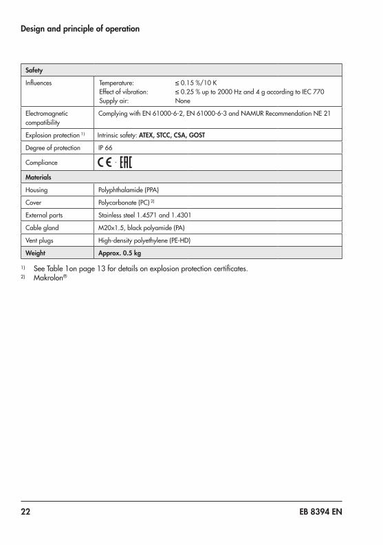
Safety
Influences Temperature: ≤0.15%/10KEffect of vibration: ≤0.25%upto2000Hzand4gaccordingtoIEC 770Supply air: None
Electromagnetic compatibility
ComplyingwithEN 61000-6-2,EN 61000-6-3andNAMURRecommendationNE 21
Explosion protection 1) Intrinsic safety: ATEX, STCC, CSA, GOST
Degree of protection IP 66
Compliance ·
Materials
Housing Polyphthalamide (PPA)
Cover Polycarbonate (PC) 2)
External parts Stainless steel 1.4571 and 1.4301
Cable gland M20x1.5, black polyamide (PA)
Ventplugs High-density polyethylene (PE-HD)
Weight Approx. 0.5 kg
1) SeeTable 1onpage 13fordetailsonexplosionprotectioncertificates.2) Makrolon®

EB 8394 EN 23
Design and principle of operation
3.5 Dimensions in mm
1422
M20 x 1.5
157.
5
108
87
42
21
62.50
25
1422
M20 x 1.5
157.
5
108
87
42
21
62.50
25
Fig. 2: Dimensional drawings for Type 3725 Positioner

24 EB 8394 EN
Design and principle of operation
Fixing levels according to VDI/VDE 3845 (September 2010)
A
M6
C
B
25
Mmin
Ød
ØD
Fixing level 2 (bracket surface)
Fixing level 1 (actuator surface)
Actuator
Dimensions in mmSize A B C Ød Mmin ØD 1)
AA0 50 25 15 5.5 for M5 66 50
AA1 80 30 20 5.5 for M5 96 50
AA2 80 30 30 5.5 for M5 96 50
AA3 130 30 30 5.5 for M5 146 50
AA4 130 30 50 5.5 for M5 146 50
AA5 200 50 80 6.5 for M6 220 501) FlangetypeF05acc.toDINENISO 5211

EB 8394 EN 25
Measures for preparation
4 Measures for preparationAfter receiving the shipment, proceed as fol-lows:1. Check the scope of delivery. Compare
the shipment received against the deliv-ery note.
2. Check the shipment for transportation damage.Reportanytransportationdam-age.
4.1 Unpacking
Risk of positioner damage due to foreign particles entering it.Do not remove the packaging and protective film/protective caps until immediately before mounting and start-up.
1. Removethepackagingfromtheposition-er.
2. Dispose of the packaging in accordance with the valid regulations.
4.2 Transporting and lifting
4.2.1 Transporting − Protect the positioner against external in-fluences(e.g.impact).
− Protect the positioner against moisture and dirt.
− Observe transport temperature depend-ing on the permissible ambient tempera-ture(seetechnicaldatainsection 3.4).
4.2.2 LiftingDue to the low service weight, lifting equip-ment is not required to lift the positioner.
4.3 Storage
Risk of positioner damage due to improper storage. − Observe storage instructions. − Avoid long storage times. − Contact SAMSON in case of different stor-age conditions or long storage periods.
Storage instructions − Protect the positioner against external in-fluences(e.g.impact,shocks,vibration).
− Do not damage the corrosion protection (coating).
− Protect the positioner against moisture and dirt. In damp spaces, prevent con-densation. If necessary, use a drying agent or heating.
− Observe storage temperature depending on the permissible ambient temperature (seetechnicaldatainsection 3.4).
− Store positioner with closed cover. − Seal pneumatic and electrical connec-
tions.
NOTICE!
NOTICE!

26 EB 8394 EN
Mounting and start-up
5 Mounting and start-up
Risk of malfunction due to incorrect sequence of mounting, installation, and start-up.Observe the prescribed sequence.
Î Sequence to be kept on mounting, install-ing, and starting up the positioner:
1. Remove the protective caps from the pneumatic connections.
2. Mount the positioner on the valve. Î Section 5.2onwards
3. Perform pneumatic installation. Î Section 5.6onwards
4. Perform electrical installation. Î Section 5.8onwards
5. Perform the settings. Î Section 7onwards
The following applies when mounting the positioner:
Î Do not mount the positioner with the vent opening (Fig. 4) facing upward.
Î Do not seal the vent opening.
5.1 Lever and pin positionThe positioner is adapted to the actuator and to the rated travel by the lever on the back of the positioner and the pin inserted into the lever.Thetraveltablesonpage 20showtheas-signment between the required lever and pin position.The positioner is equipped with the M lever (pin position 35)asstandard(seeFig. 3).
Removing the lever and changing the pin position:
Incorrect removal of the lever will damage the positioner.Only remove the lever when it is positioned at the bottom mechanical stop.
1. Move the lever to the bottom mechanical stop(seeFig. 4)andholditinplace.Un-do and remove the nut using a wrench (widthacrossflatsSW10).
2. Removetheleverfromtheshaft.3. Insert pin in position as listed in the
travel table.4. Fasten the lever.
NOTICE!
NOTICE!

EB 8394 EN 27
Mounting and start-up
Fig. 3: M lever with pin position 35
Top stop
Bottom stopVentopening
Fig. 4: Mechanical stops and vent opening

28 EB 8394 EN
Mounting and start-up
5.2 Direct attachment
5.2.1 Type 3277-5 and Type 2780-2 Actuators
Î Requiredmountingpartsandaccesso-ries:Table 2onpage 16.
Î Observetraveltablesonpage 20.
Actuator with 120 cm² diaphragm areaDepending on the type of positioner attach-ment, the signal pressure is routed either left or right of the yoke through a hole to the ac-tuator diaphragm.
Î Depending on the fail-safe action of the actuator "actuator stem extends" or "ac-tuatorstemretracts",firstattachtheswi-tchover plate (9) to the actuator yoke (while aligning it with the corresponding symbol for left or right attachment ac-cordingtothemarking,seeFig. 6).
1. Mount connecting plate (6) or pressure gauge bracket (7) with pressure gauges on the positioner, making sure the two seals (6.1) are seated properly.
2. Screw the screw plug (4) on the back of the positioner into the hole below it (park position)(seeFig. 8)andsealthesignalpressure output on the connecting plate (6) or on the pressure gauge bracket (7) with the stopper (5) included in the ac-cessories.
3. Place follower clamp (3) on the actuator stem, align it and screw tight so that the mounting screw is located in the groove of the actuator stem.
4. 15 mm travel:Keepthefollowerpin(2)on the M lever (1) on the back of the po-sitioner in the pin position 35 (delivered state). 7.5 mm travel:Removethefol-lower pin (2) from the pin position 35, reposition it in the hole for pin position 25 and screw tight.
5. Insert formed seal (15) into the groove of the positioner housing.
6. Place positioner on the actuator in such a manner that the follower pin (2) rests on top of the follower clamp (3). While do-ing this, press on the ribbed area shown inFig. 5tolockthepick-upleverinthetop position. The lever (1) must rest on the follower clamp with spring force.
Fig. 5: Locking the pick-up lever in position
7. Mount the positioner on the actuator us-ingthetwofixingscrews.
EB 8394 EN 29
Mounting and start-up
9 11Supply 9 Output 38
56
7
3
21
15
6.1
1.11.2
8
4
16
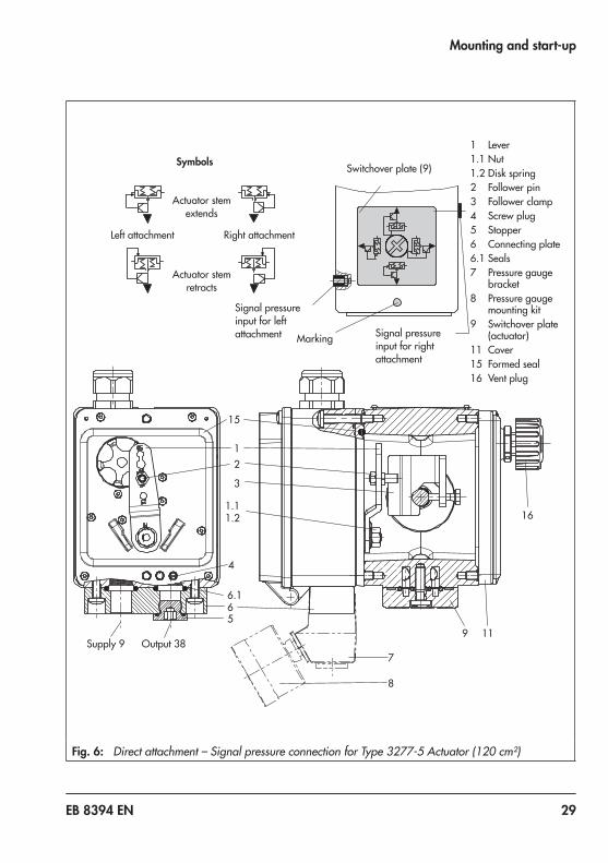
1 Lever1.1 Nut1.2 Disk spring2 Follower pin3 Follower clamp4 Screw plug5 Stopper6 Connecting plate6.1 Seals7 Pressure gauge
bracket8 Pressure gauge
mounting kit9 Switchover plate
(actuator)11 Cover15 Formed seal16 Ventplug
Symbols
Actuator stem extends
Switchover plate (9)
Marking
Actuator stem retracts
Signal pressure input for right attachment
Signal pressure input for left attachment
Left attachment Rightattachment
Fig. 6: Direct attachment – Signal pressure connection for Type 3277-5 Actuator (120 cm²)

30 EB 8394 EN
Mounting and start-up
8. Mount cover (11) on the other side. Make sure that the vent plug is located at the bottom when the control valve is in-stalled to allow any condensed water thatcollectstodrainoff(Fig. 7).
Additional solenoid valveIf a solenoid valve is additionally mounted onto the actuator, the signal pressure port at the back of the positioner must be sealed (seeFig. 8).Todothis,unscrewthescrewplug located in the middle hole (screw plug in park position) and screw it into the signal pressure port to seal it.In this case, route the signal pressure from the signal pressure output to the actuator over the connecting plate (6) or pressure gauge bracket (7). The connecting plate (ac-cessories for the actuator) replaces the swi-tchover plate (9).
The switchover plate and connecting plate are accessories for the actuator (120 cm²). They are listed in section 3.2 on page 16.
Note
Cover Ventplug
Fig. 7: Cover with vent plug when the valve is installed

EB 8394 EN 31
Mounting and start-up
Screw plug (4) (signal pressure port)
Park position
Fastening screw
Fig. 8: Signal pressure port and park position for screw plug

32 EB 8394 EN
Mounting and start-up
5.2.2 Type 3277 Actuator Î Requiredmountingpartsandaccesso-ries:Table 3onpage 16.
Î Observetraveltablesonpage 20.
Actuators with 240 to 700 cm² effective areasThe positioner can be mounted either on the left or right side of the yoke. The signal pres-sure is routed to the actuator over the con-nection block (12), for actuators with fail-safe action "actuator stem extends" internal-ly through a hole in the valve yoke and for "actuator stem retracts" through an external pipe.Place follower clamp (3) on the actuator stem, align it and screw tight so that the mounting screw is located in the groove of the actuator stem.1. Foractuators240and350 cm²with
15 mmtravel,keepthepin(2)inpinpo-sition 35.Foractuatorswith355or700 cm²,re-move the pin (2) on M lever (1) on the back of the positioner from pin position 35, reposition it in the hole for pin posi-tion 50 and fasten tight.
2. Insert formed seal (15) in the groove of the positioner housing.
3. Place positioner on the actuator in such a manner that the pin (2) rests on top of the follower clamp (3).
4. While doing this, press on the ribbed ar-ea to lock the lever in the top position (seeFig. 5).
The lever (1) must rest on the follower clamp with spring force.Fasten the positioner on the actuator us-ingthetwofixingscrews.
5. Make sure that the tip of the gasket (16) projecting from the side of the connec-tion block is positioned to match the ac-tuator symbol for the actuator's fail-safe action "actuator stem extends" or "actua-tor stem retracts". If this is not the case, unscrew the three fastening screws and lift off the cover. Turn the gasket (16) by 180° and re-insert it.
6. Place the connection block (12) with the associated seals against the positioner and the actuator yoke and fasten using the screw (12.1).
7. For actuators with fail-safe action "actua-tor stem retracts", additionally remove the stopper (12.2) and mount the exter-nal signal pressure pipe.
8. Mount cover (11) on the other side. Make sure that the vent plug is located at the bottom when the control valve is in-stalled to allow any condensed water thatcollectstodrainoff(seeFig. 7onpage 30).
EB 8394 EN 33
Mounting and start-up
2
10 15 1 2 3 11
1.11.2
12.11216
16
12.2SUPPLY
A
Ansicht A
1
2
10 15 1 2 3 11
1.11.2
12.11216
16
12.2SUPPLY
A
View A
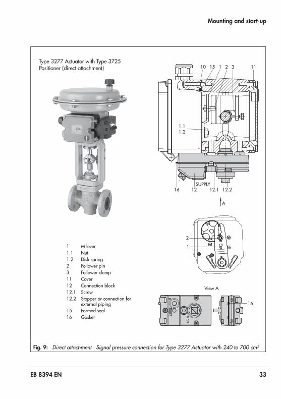
11 M lever1.1 Nut1.2 Disk spring2 Follower pin3 Follower clamp11 Cover12 Connection block12.1 Screw12.2 Stopper or connection for
external piping15 Formed seal16 Gasket
Type3277ActuatorwithType 3725Positioner (direct attachment)
Fig. 9: Direct attachment · Signal pressure connection for Type 3277 Actuator with 240 to 700 cm²

34 EB 8394 EN
Mounting and start-up
5.3 Attachment according to IEC 60534-6
The positioner is attached to the control valve usingaNAMURbracket(10).
Î Requiredmountingpartsandaccesso-ries:Table 5onpage 18.
Î Observetraveltablesonpage 20.1. Screw the two bolts (14) to the bracket
(9.1) of the stem connector (9), place the follower plate (3) on top and use the screws (14.1) for fastening.
2. FastentheNAMURbracket(10)tothecontrol valve.
− ForvalvewithNAMURrib:FastentheNAMURbracket(10)usingtheM8screw (11) and toothed lock washer di-rectly to the yoke hole.
− For valves with rod-type yoke: Place the two U-bolts (16) around the stem. Posi-tiontheNAMURbracket(10)andfastenit using the nuts, washers and toothed lock washers.
3. AligntheNAMURbracket(10)sothatitsmounting holes are approximately in line to the middle of the travel scale indicator (15) (the slot of the follower plate must becentrallyalignedwiththeNAMURbracket at mid valve travel).
4. Mount connecting plate (6) or pressure gauge bracket (7) with pressure gauges (8) on the positioner, making sure the two seals (6.1) are seated properly.
5. PlacepositionerontheNAMURbracketin such a manner that the pin (2) rests in
the slot of the follower plate (3). Adjust the lever (1) correspondingly.FastenthepositionertotheNAMURbracket using its two mounting screws.

EB 8394 EN 35
Mounting and start-up
1 Lever1.1 Nut1.2 Disk spring2 Follower pin3 Follower plate6 Connecting plate6.1 Seals7 Pressure gauge brack-
et8 Pressure gauge9 Stem connector9.1 Bracket10 NAMURbracket11 Screw14 Bolt14.1 Screws15 Travel indicator scale16 U-bolt
10
11
14.1
3
14
11.21.12
9.1
9
6.1 6 7 8
15
Attachment to rod-type yoke20to35 mmroddiameter
16
Fig. 10: Attachment according to IEC 60534-6

36 EB 8394 EN
Mounting and start-up
5.4 Attachment to Type 3372 Actuator (V2001)
TheType 3725PositionerisalreadyincludedinthescopeofdeliveryforSeriesV2001Valves(Fig. 11).Theattachmentisbrieflydescribedbelowtoallow conversion work to be performed.
Actuator with 120/350 cm², stem extendsThe signal pressure is routed through the cor-responding port in the support element to the actuator diaphragm.
Î Thread the screw plug on the positioner into the hole below (park position) (see Fig. 8onpage 31).
Actuator with 120/350 cm², stem retractsThe signal pressure is routed through piping at the side of the support element to the actu-ator diaphragm.
Attachment including solenoid valveThe signal pressure is routed from the output port of the positioner to the solenoid valve and through a corresponding hole in the support element to the actuator diaphragm.

EB 8394 EN 37
Mounting and start-up
Type 3372 Actuator, version with 120 cm²
Type 3372 Actuator, version with 350 cm²
Fig. 11: Mounting on Type 3372 Actuator

38 EB 8394 EN
Mounting and start-up
5.5 Attachment to rotary actu-ators
The positioner is mounted to the rotary actu-ator using a mounting bracket.
Î Requiredmountingpartsandaccesso-ries:Table 6onpage 18.
Î Before attaching the positioner onto the SAMSONType 3278RotaryActuator(160 cm²)orVETECType S160Actuator,firstmounttheadapter(13)tothefreeend of the shaft end using four screws (10, 1).
1. Place follower clamp (3) on the slotted actuator shaft or adapter (13).
2. Placecouplingwheel(4)withflatsidefacing the actuator on the follower clamp (3).RefertoFig. 12toalignslotsothatitmatches the direction of rotation when the valve is in its closed position.
3. Fasten the coupling wheel (4) and follow-er clamp (3) tightly onto the actuator shaft using screw (4.1) and disk spring (4.2).
4. Mount connecting plate (6) or pressure gauge bracket (7) with pressure gauges (8) on the positioner, making sure the two seals are seated properly.
5. Fasten the mounting bracket (10) to the actuator using four screws (10.1).
6. Unscrew the standard follower pin (2) from the positioner's M lever (1). Use the metalfollowerpin(Ø5 mm)includedinthe mounting kit and screw tight into the hole for pin position 90°.
7. Place positioner on the mounting bracket (10) and fasten tight. Taking the actua-tor's direction of rotation into account, adjust lever (1) so that it engages in the slot of the coupling wheel (4) with its fol-lowerpin(Fig. 13).
Î The lever (1) must be parallel to the long side of the positioner when the actuator is at half its angle of rotation.
8. Stick the scale plate on the coupling wheel (4) so that the arrow tip indicates the closed position and it can be easily read when the valve is installed.
Fig. 12: Direction of rotation

EB 8394 EN 39
Mounting and start-up
1 Lever1.1 Nut1.2 Disk spring2 Follower pin3 Follower clamp4 Coupling wheel4.1 Screw4.2 Disk spring5 Actuator shaft
6 Connecting plate6.1 Seals7 Pressure gauge bracket8 Pressure gauge
mounting kit10 Mounting bracket10.1 Screws13 Adapter
8050
60
30
66.178
11.11.2
2
4.1
3
10.1
10
5
4
4.2
30
5080
66.178
11.11.2
2
4.1
3
10.1
10
5
13
10.1
4
4.2
AttachmenttoSAMSONType 3278RotaryActuator(160 cm²)orVETEC
Type S160Actuator
AttachmentaccordingtoVDI/VDE 3845,level1
Fig. 13: Attachment to rotary actuators

40 EB 8394 EN
Mounting and start-up
5.5.1 Heavy-duty version Î Requiredmountingpartsandaccesso-ries:Table 6onpage 18.
Prepare actuator and mount possibly re-quired adapter supplied by the actuator manufacturer.1. Mount the housing (10) onto the rotary
actuator.IncaseofVDI/VDEattachment,place spacers (11) underneath, if neces-sary.
2. For SAMSON Type 3278 and VETEC S160 Rotary Actuators, screw the adapt-er (5) onto the free end of the shaft or place adapter (5.1) onto the shaft of the VETEC R Actuator. Place adapter (3) on-to Type 3278, VETEC S160 and VETEC R Actuators. For VDI/VDE version, this step depends on the actuator size.
3. Stick adhesive label (4.3) onto the cou-pling in such a manner that the yellow part of the sticker is visible in the window of the housing when the valve is OPEN. Adhesive labels with explanatory sym-bols are enclosed and can be stuck on the enclosure, if required.
4. Fasten coupling wheel (4) on the slotted actuator shaft or adapter (3) using screw (4.1) and disk spring (4.2).
5. Unscrew the standard follower pin (2) from the positioner's M lever (1). Attach thefollowerpin(Ø5 mm)includedinthemounting kit to pin position 90°.
6. Mount connecting plate (6) for required G ¼connectingthreadorpressuregauge bracket (7) with pressure gauges on the positioner, making sure the two
seals (6.1) are seated properly. Dou-ble-acting springless rotary actuators re-quiretheuseofareversingamplifieronthe connection side of the positioner housing(refertosection 5.5.2).
7. For actuators with a volume of less than 300cm³,fittherestriction(orderno.1400-6964) into the signal pressure out-put of the positioner (or the output of the pressure gauge bracket or connecting plate).
8. Fasten the positioner onto the adapter plate (12).
9. Place the positioner together with the adapter plate on the housing (10) and screw it tight. Taking the actuator's direc-tion of rotation into account, adjust lever (1) so that it engages in the correct slot withitsfollowerpin(Fig. 14).
1
10
4
Actuator turning counterclockwise
Actuator turning clockwise
Fig. 14: Direction of rotation

EB 8394 EN 41
Mounting and start-up
66.178
11.11.2
212
4.1
3
10.1
10
11
5
4.344.2
4.1
3
5.1
5
10.1
10
4.344.2
1 Lever1.1 Nut1.2 Disk spring2 Follower pin3 Adapter4 Coupling wheel4.1 Screw4.2 Disk spring4.3 Adhesive label5 Actuator shaft or
adapter
5.1 Adapter 6 Connecting plate (only
forG ¼) 6.1 Seals 7 Pressure gauge bracket 8 Pressure gauge
mounting kit10 Adapter housing10.1 Screws11 Distance piece12 Adapter plate
Fit restriction into signal pressure outputforactuatorswith<300 cm³volume
SAMSON Type 3278VETEC S160, VETEC R
Attachment according to VDI/VDE 3845 (Sept. 2010) Fixing level 1, AA1 to AA4 size (see page 24)
Fig. 15: Attachment to rotary actuators (heavy-duty version)

42 EB 8394 EN
Mounting and start-up
5.5.2 Mounting the Type 3710 Reversing Amplifier
WhenaType 3710ReversingAmplifierisused, a connecting plate is placed between thepositionerandreversingamplifier.Thereversingamplifierisfastenedtogetherwiththe connecting plate to the positioner using screws(Fig. 16).
The screws supplied with the connecting plate have a TORX PLUS® profile (size 25 IP) and must be tightened using a suitable tool.
DetailsontheType 3710ReversingAmplifi-er: Mounting and Operating Instructions u EB 8392
Connecting plate
Type 3710ReversingAmplifier
Self-tappingscrewwithTORXPLUS®profile,size25IP
Fig. 16: Mounting the Type 3710 Reversing Amplifier
Note

EB 8394 EN 43
Mounting and start-up
5.6 Pneumatic connections
Risk of injury by possible movement of the actuator stem after connecting the signal pressure.Do not touch or block the actuator stem.
Incorrect connection of the supply air will damage the positioner and will lead to mal-function. − Screw the screw fittings into the connecting plate, pressure gauge mounting block or connection block from the accessories. − Keep the length of the line as short as pos-sible to avoid delays in control signal transmission.
The pneumatic connections are optionally designedasaborewith¼NPTorG¼thread.Thecustomaryfittingsformetalandcopper pipes or plastic hoses can be used.
Risk of malfunction due to failure to comply with required air quality.Only use supply air that is dry and free of oil and dust.Read the maintenance instructions for up-stream pressure reducing stations.Blow through all air pipes and hoses thor-oughly before connecting them.
5.7 Connecting the supply air
Risk of malfunction due to incorrect sequence of mounting, installation, and start-up.Keep the following sequence.1. Remove the protective caps from the
pneumatic connections.2. Mount the positioner on the valve.3. Connect the supply air.4. Connect the electrical power.5. Perform the start-up settings.
5.7.1 Signal pressure connec-tion
The signal pressure connection depends on how the positioner is mounted onto the actu-ator:
Type 3277 Actuator Î Thesignalpressureconnectionisfixedwhen the positioner is directly attached totheType 3277Actuator.
WARNING!
NOTICE!
NOTICE!
NOTICE!
44 EB 8394 EN
Mounting and start-up
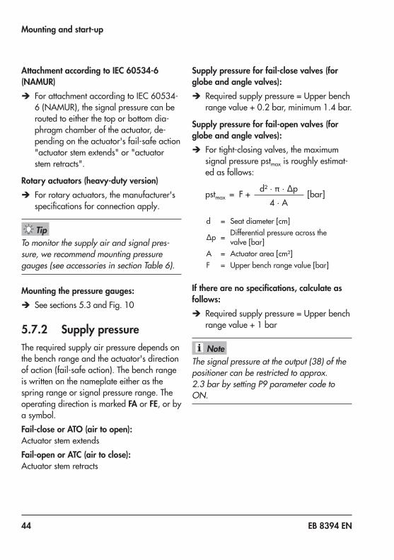
Attachment according to IEC 60534-6 (NAMUR)
Î ForattachmentaccordingtoIEC 60534-6(NAMUR),thesignalpressurecanberouted to either the top or bottom dia-phragm chamber of the actuator, de-pending on the actuator's fail-safe action "actuator stem extends" or "actuator stem retracts".
Rotary actuators (heavy-duty version) Î For rotary actuators, the manufacturer's specificationsforconnectionapply.
To monitor the supply air and signal pres-sure, we recommend mounting pressure gauges (see accessories in section Table 6).
Mounting the pressure gauges: Î Seesections 5.3andFig. 10
5.7.2 Supply pressureThe required supply air pressure depends on the bench range and the actuator's direction of action (fail-safe action). The bench range is written on the nameplate either as the spring range or signal pressure range. The operating direction is marked FA or FE, or by a symbol.Fail-close or ATO (air to open):Actuator stem extendsFail-open or ATC (air to close):Actuator stem retracts
Supply pressure for fail-close valves (for globe and angle valves):
Î Requiredsupplypressure=Upperbenchrangevalue+0.2 bar,minimum1.4bar.
Supply pressure for fail-open valves (for globe and angle valves):
Î For tight-closing valves, the maximum signal pressure pstmax is roughly estimat-ed as follows:
pstmax = F + d²·π·∆p [bar]4 · A
d = Seatdiameter[cm]
∆p = Differential pressure across the valve[bar]
A = Actuatorarea[cm²]F = Upperbenchrangevalue[bar]
If there are no specifications, calculate as follows:
Î Requiredsupplypressure=Upperbenchrange value + 1 bar
The signal pressure at the output (38) of the positioner can be restricted to approx. 2.3 bar by setting P9 parameter code to ON.
Tip
Note

EB 8394 EN 45
Mounting and start-up
5.8 Electrical connections
Risk of the formation of an explosive atmosphere.For installation in hazardous areas, observe the relevant standards that apply in the country of use.Standard applicable in Germany: EN 60079-14: 2008 (VDE 0165, Part 1) Explosive Atmo-spheres – Electrical Installations Design, Selection and Erection.
Incorrect electrical connection will render the explosion protection unsafe. − Adhere to the terminal assignment. − Do not undo the enameled screws in or on the housing. − Do not exceed the maximum permissible values specified in the EC type examination certif-icates when interconnecting intrinsically safe electrical equipment (Ui or U0, li or I0, Pi or P0, Ci or C0 and Li or L0).
DANGER!
WARNING!
Selecting cables and wires Î Observe clause 12 of EN 60079-14 (VDE 0165, Part 1) for installation of the intrinsically safe circuits.
Î Clause 12.2.2.7applieswhenrunningmulti-core cables and wires with more than one intrinsically safe circuit.
Î Radial thickness of the insulation of a conductor for common insulating materi-als (e.g. polyethylene): minimum 0.2 mm.
Î Diameter of an individual wire in a fine-strandedconductor: minimum 0.1 mm.
Î Strip 8 mm insulation off the wire ends. Î Protect the conductor ends against splic-ing, e.g. by using wire-end ferrules.
Î Cable glands available: SeeTable 7onpage 19

46 EB 8394 EN
Mounting and start-up
Equipment for use in zone 2/zone 22In equipment operated according to type of protectionEx nA II(non-sparkingequipment)accordingtoEN 60079-15:2003:
Î Circuits may be connected, interrupted, or switched while energized only during installation, maintenance, or repair.
Equipment connected to energy-limited cir-cuitswithtypeofprotectionEx nL(ener-gy-limited equipment) according to EN 60079-15:2003:
Î Equipment may be switched under nor-mal operating conditions.
Themaximumpermissiblevaluesspecifiedinthe statement of conformity and its addenda apply when interconnecting the equipment with energy-limited circuits in type of protec-tionEx nL IIC.
5.8.1 Electric power supply Î Only use a current source and never a voltage source!
Î Keepthereferencevariablewithinthestaticdestructionlimitof±33 V.
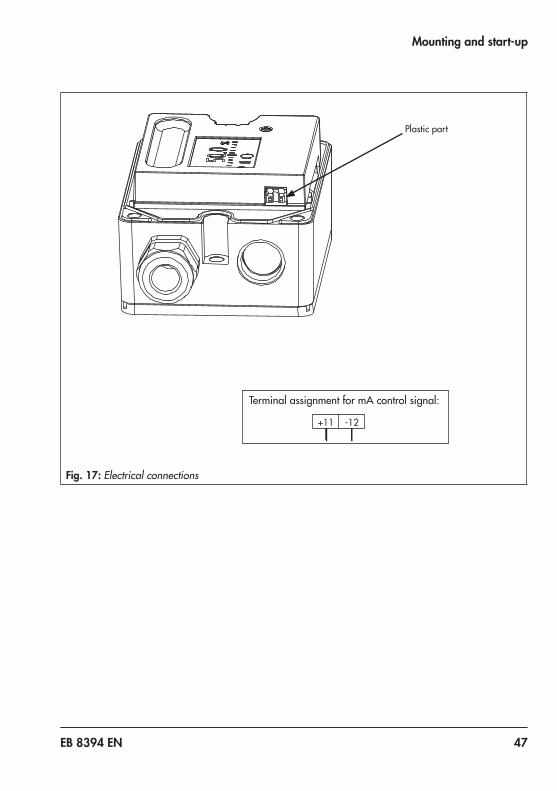
5.8.2 Cable entryThe M20x1.5 cable gland is designed for a clampingrangeof6to12 mm.The cage clamp terminals hold wire cross-sectionsof0.2to1.5 mm².
Î To unlock the cage clamp terminals: place a slotted screwdriver on the plastic part(Fig. 17)andlightlypushitintotheterminal block.
Î Insert or remove the wire without force.
5.8.3 Connecting the electrical power
Risk of malfunction due to incorrect sequence of mounting, installation, and start-up.Keep the following sequence.1. Remove the protective caps from the
pneumatic connections.2. Mount the positioner on the valve.3. Connect the supply air.4. Connect the electrical power.5. Perform the start-up settings.
Î Connect the electrical power (mA signal) asshowninFig. 17.
NOTICE!
EB 8394 EN 47
Mounting and start-up
Plastic part
Terminal assignment for mA control signal:
+11 -12
Fig. 17: Electrical connections

48 EB 8394 EN
Operation
6 Operation
6.1 Operating controlsThree capacitive keys are used to operate the positioner and allow the user to navigate with-inthemenuonthedisplay(Fig. 18).Additionally,thevolumerestrictionallowstheairoutputcapacity to be adapted to the size of the actuator.
6.1.1 Capacitive keys: Up: Confirm: Down
Touch or key to select a parameter code (P0 to P20). Then touch keytoconfirmtheselected code.To save changes to parameters in a non-volatile memory, proceed as follows:
Î After changing parameters, press or to change to Code P0 or Î wait three minutes until the display returns automatically to P0.
− The icon on the display indicates that the changed parameter settings have not yet been saved in the non-volatile memory. − The selected parameter code remains active until you change the setting or exit the param-eter code. − After changing settings in P2, P4 and P8 parameter codes, the positioner must be re-initial-ized.
6.1.2 Volume restriction QThe volume restriction serves to adapt the air output capacity to the size of the actuator. Two fixedsettingsarepossible(refertosection7.3).
Note

EB 8394 EN 49
Operation
6.1.3 DisplayIcons which are assigned to certain codes and functions are indicated on the display (Fig. 18).Thebarelementsindicatethesystemdeviationthatdependsonthesign(+/–)andthevalue.Onebarelementappearsper1 %systemdeviation.If the positioner has not yet been initialized, the lever position in degrees in relation to the mid-axis is indicated. One bar element corresponds to approximately a 7° angle of rotation.If the fault indication icon is displayed, press or until ERR is displayed to view the E0 to E15errorcodes(seesection 9.2).
Reading MeaningESC StopErr MalfunctionLOW w too lowMAN Manual modeMAX Maximum rangeRST ResetINIT InitializationON/OFF Activated/deactivatedZERO Zero calibration
%
Smm
%mm
Confirm
Up
Settings not yet saved in a non-volatile memory
Unit
Bar graph for system deviation
Fault
Manual mode
Closed-loop control
Parameter/error code
Fail-safe position active
Operation locked
Down
Fig. 18: Display with all readings

50 EB 8394 EN
Operating the positioner
7 Operating the positionerBeforestart-up,mountthepositionerfollowingthesequencedescribedinsection 5.Applytheelectricreferencevariabletostartupthepositioner.Refertosection 5.8.3.
− LOW on the display indicates that the reference variable is lower than 3.8 mA. − The positioner is ready for operation with its default settings for most applications. − After connecting the electrical signal, the positioner performs a calibration of the capacitive keys which takes approx. three seconds. During this time, do not touch the key panel. Otherwise, the keys will not work properly. Disconnect and reconnect the electrical signal to restart the calibration of keys.
Reading after connecting the power supplyReadingwhenthepositionerhasnot yet been initialized
S Code P0 is displayed. The fault indication icon and S (fail-safe po-sition) appear on the display.The reading indicates the lever position in degrees in relation to the mid-axis.
Readingwhenthepositionerhasbeeninitialized:
%
Code P0 is displayed. The positioner is in closed-loop operation indi-cated by the closed-loop operation icon.The indicated value corresponds to the control position in %.Details on initialization of the positioner: section 7.8.
Note

EB 8394 EN 51
Operating the positioner
7.1 Adapting the displayThe display reading direction can be rotated by 180°. If the displayed data appear upside down, proceed as follows:
1. Touch or until Code P1 appears.2. Press to confirm the selected code. P1 blinks.3. Touch or until the display is set in the desired direction.4. Press to confirm display direction.
7.2 Enabling configuration to change parametersBeforechangingparametersettingsinaninitializedpositioner,configurationmustbeen-abledfirstbyselectingCodeP19:
LOCK and the key icon indicate that the configuration is locked. De-activate locking as follows:1. Touch or until Code P19 appears.2. Press to confirm the selected code. P19 blinks.3. Touch or until OPEN is displayed.4. Press to enable configuration.
If no settings are entered within three minutes, the enabled configuration function becomes invalid.
Note
52 EB 8394 EN
Operating the positioner
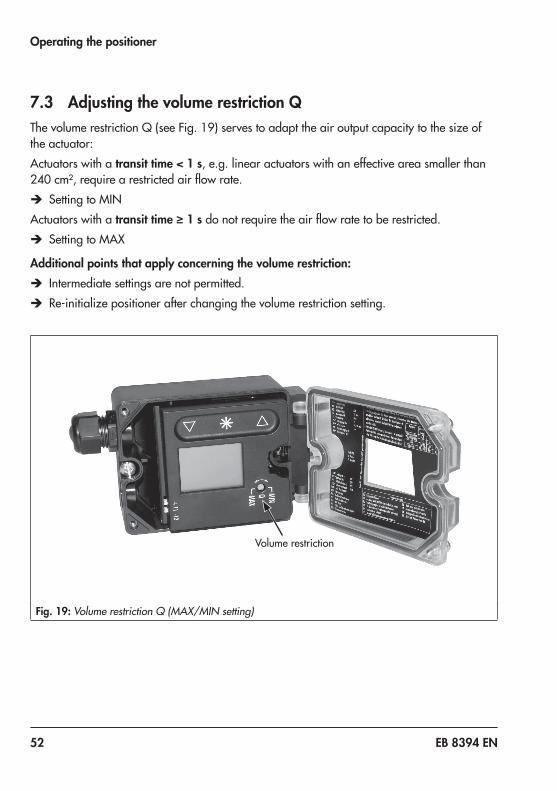
7.3 Adjusting the volume restriction QThevolumerestrictionQ(seeFig. 19)servestoadapttheairoutputcapacitytothesizeofthe actuator:Actuators with a transit time < 1 s, e.g. linear actuators with an effective area smaller than 240 cm²,requirearestrictedairflowrate.
Î Setting to MINActuators with a transit time ≥ 1 sdonotrequiretheairflowratetoberestricted.
Î Setting to MAX
Additional points that apply concerning the volume restriction: Î Intermediate settings are not permitted. Î Re-initializepositionerafterchangingthevolumerestrictionsetting.
Volumerestriction
Fig. 19: Volume restriction Q (MAX/MIN setting)

EB 8394 EN 53
Operating the positioner
7.4 Entering the air action − ATO (air to open) applies to a valve opening as the signal pressure increases. − ATC (air to close) applies to a valve closing as the signal pressure increases.
The signal pressure is the pneumatic pressure at the output of the positioner applied to the actuator.
Default air action: ATOChange the air action (enable configuration as described in sec-tion 7.2):1. Touch or until Code P2 appears.2. Press to confirm selected code. P2 blinks.3. Touch or until the required air action appears.4. Press to confirm setting.
The changed air action first becomes effective after the positioner has been re-initialized.
7.5 Entering the direction of actionThe direction of action (P7) is set to increasing/increasing (>>) by default, i.e. when the posi-tioner is initialized, 0 % is displayed when the valve is closed and 100 % when the valve is fullyopen.Ifnecessary,thedirectionofactioncanbechanged(enableconfigurationasde-scribedinsection 7.2):
Changing the direction of action to increasing/decreasing:1. Touch or until Code P7 appears.2. Press to confirm selected code. P7 blinks.3. Touch or until <> appears.4. Press to confirm setting.
Note

54 EB 8394 EN
Operating the positioner
The following correlation applies:
Valve CLOSED OPENDisplay 0% 100%
Direction of action increasing/increasing (>>) 4 mA 20 mA
Direction of action increasing/decreasing (<>) 20 mA 4 mA
7.6 Limiting the signal pressureIf the maximum actuator force is too high for the valve used, the signal pressure limit can be activated in Code P9.Thepressureisthenlimitedtoapprox.2.3 bar.
Activate the signal pressure limitation (enable configuration as de-scribed in section 7.2):1. Touch or until Code P9 appears.2. Press to confirm selected code. P9 blinks.3. Touch or until ON appears.4. Press to confirm setting.
EB 8394 EN 55
Operating the positioner
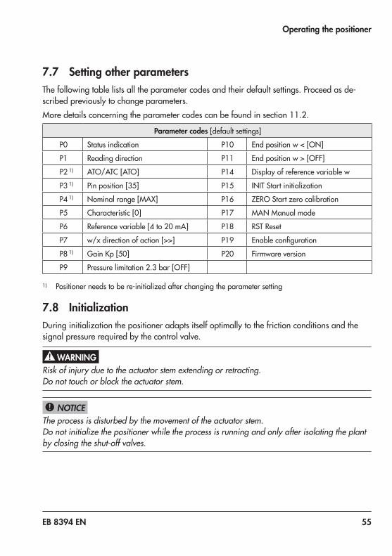
7.7 Setting other parametersThe following table lists all the parameter codes and their default settings. Proceed as de-scribed previously to change parameters.Moredetailsconcerningtheparametercodescanbefoundinsection 11.2.
Parameter codes[defaultsettings]
P0 Status indication P10 Endpositionw<[ON]
P1 Readingdirection P11 Endpositionw>[OFF]
P2 1) ATO/ATC[ATO] P14 Display of reference variable w
P3 1) Pinposition[35] P15 INIT Start initialization
P4 1) Nominalrange[MAX] P16 ZEROStartzerocalibration
P5 Characteristic[0] P17 MAN Manual mode
P6 Referencevariable[4to20mA] P18 RSTReset
P7 w/xdirectionofaction[>>] P19 Enableconfiguration
P8 1) GainKp[50] P20 Firmware version
P9 Pressurelimitation2.3bar[OFF]
1) Positioner needs to be re-initialized after changing the parameter setting
7.8 InitializationDuring initialization the positioner adapts itself optimally to the friction conditions and the signal pressure required by the control valve.
Risk of injury due to the actuator stem extending or retracting.Do not touch or block the actuator stem.
The process is disturbed by the movement of the actuator stem.Do not initialize the positioner while the process is running and only after isolating the plant by closing the shut-off valves.
WARNING!
NOTICE!
56 EB 8394 EN
Operating the positioner
The type and extent of self-adaptation depends on the preset parameters. MAX applies as the default setting for the nominal range (Code P4). During the initialization process, the po-sitioner determines the total travel range or rotational range of the valve (from the CLOSED position to the opposite end position).Alternatively, a different travel can be selected in Code P4(seecodelistinsection 11.2).
The travel set in Code P4 is only limited during initialization. However, it might be exceeded in closed-loop control when the control signal is higher than 20 mA.
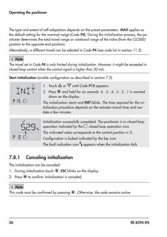
Start initialization(enableconfigurationasdescribedinsection 7.2).
1. Touch or until Code P15 appears.2. Press and hold for six seconds. 6...5...4...3...2...1 is counted
down on the display.The initialization starts and INIT blinks. The time required for the ini-tialization procedure depends on the actuator transit time and can take a few minutes.
%
Initialization successfully completed. The positioner is in closed-loop operation indicated by the closed-loop operation icon.The indicated value corresponds to the control position in %.Configuration is locked indicated by the key icon.The fault indication icon appears when the initialization fails.
7.8.1 Canceling initializationThe initialization can be canceled:1. During initialization touch : ESC blinks on the display.2. Press toconfirm:Initializationiscanceled.
This code must be confirmed by pressing . Otherwise, the code remains active.
Note
Note

EB 8394 EN 57
Operating the positioner
Initial state 1:The positioner is not initialized.The positioner goes to the fail-safe position after the initialization process has been canceled.Initial state 2:The positioner is initialized.On canceling a new initialization process, the positioner returns to closed-loop operation. The settings of the previous initialization are used.A new initialization can be started directly afterwards.
7.9 Zero calibrationIn case of inconsistencies in the closing position of the valve, e.g. with soft-seated plugs, it might be necessary to recalibrate zero over Code P16(enableconfigurationasdescribedinsection 7.2).Start the zero calibration by activating Code P16 as follows:
1. Touch or until Code P16 appears.2. Press and hold for six seconds. 6...5...4...3...2...1 is counted
down on the display.Zero calibration starts, ZERO blinks on the display.The time required for the initialization procedure depends on the ac-tuator transit time and can take a few minutes.
The positioner moves the control valve to the CLOSED position and recalibrates the internal electric zero point.When the zero calibration has been successfully completed, the positioner changes to closed-loop operation.

58 EB 8394 EN
Operating the positioner
7.9.1 Canceling zero calibrationZero calibration can be canceled:1. During zero calibration touch : ESC blinks on the display.2. Press toconfirm:Zerocalibrationiscanceled.
This code must be confirmed by pressing . Otherwise, the code remains active.
The positioner changes to closed-loop operation without performing a zero calibration. A new zero calibration can be started directly afterwards.
7.10 Manual modeThe valve position can be moved as follows using the Manual mode function:
%
Enable configuration as described in section 7.2.1. Touch or until Code P17 appears.2. Press and hold for six seconds. 6-5-4-3-2-1- is counted down
on the display and P17 blinks.The manual set point is indicated on the display of an initialized positioner.The lever position in degrees in relation to the longitudinal axis is indicated on the display of a positioner that has not been initial-ized.
3. Touch or to change the manual set point.
Initialized positionerThe manual mode starts using the last set point used in closed-loop operation, ensuring a bumpless changeover.The bar elements on the display indicate the system deviation between the manual set point and set point used for closed-loop control while manually moving the valve in Code P17.Themanualsetpointisadjustedinstepsof0.1%.Youcanmovethevalvecontrolledwithinitsrange.
Note

EB 8394 EN 59
Operating the positioner
Positioner that has not been initializedTouch or for a long time to move the valve manually.The valve is only moved in one direction uncontrolled. The bar elements on the display indi-cate the change in direction.Touch to deactivate manual mode.
The Manual mode function can only be exited as described or by interrupting the electrical supply (cold start). The positioner does not automatically exit this function and return to the display showing the status indication.
7.11 ResetA reset causes an initialization to be undone and all parameters settings are reset to the de-faultsettings(seecodelistinsection 11.2).
Enable configuration as described in section 7.2.1. Touch or until Code P18 appears.2. Press and hold for six seconds. 6...5...4...3...2...1 is counted
down on the display.RST blinks while is pressed. As soon as the key is released, the reset process is completed and the display returns to status indication (P0).
The fault indication icon is displayed after a reset since the positioner needs to be re-initial-ized. The error code E2 is also activated (see section 9.2).
Note
Note
60 EB 8394 EN
Servicing
8 Servicing
The positioner was checked by SAMSON before it left the factory. − The product warranty becomes void if ser-vice or repair work not described in these instructions is performed without prior agreement by SAMSON's After-sales Ser-vice department. − Only use original spare parts by SAMSON, which comply with the original specifications.
TheType 3725Positioner requires no main-tenance.Therearefilterswitha100 µmmesh size in the pneumatic connections for supply and output which can be removed and cleaned, if required.
Î Observe the maintenance instructions of any upstream supply air pressure reduc-ing stations.
8.1 Cleaning the window in the cover
Incorrect cleaning will damage the window.The window is made of Makrolon® and will be damaged when cleaned with abrasive cleaning agents or agents containing sol-vents. − Do not rub the window dry. − Do not use any cleaning agents containing chlorine or alcohol or abrasive cleaning agents. − Use a non-abrasive, soft cloth for cleaning.
8.2 Preparation for return ship-ment
Proceed as follows to return valves to SAMSON:1. Put the control valve out of operation.
See associated valve documentation.2. Removethepositioner(seesection 10.2).3. Send the positioner to your nearest
SAMSON subsidiary. SAMSON subsid-iaries are listed on our website at u www.samson.de>Contact.
NoteNOTICE!

EB 8394 EN 61
Malfunctions
9 MalfunctionsIn case of a fault, the fault indication icon is displayed. Switch past Code P0 or P20 to dis-play the respective error code E0 to E15 together with ERRappearonthedisplay.Refertotheerrorcodelistinsection 9.2forthecauseoftheerrorsandtherecommendedaction.Example:If, for instance, a travel has been entered in Code P4 (nominal range) which is larger than the maximum valve travel possible, the initialization process would be interrupted (E2 error code) because the rated travel would not have been reached (E6 error code). The valve moves to the fail-safe position (S indicated on the display).
S Display of the fault indication: − Fault indication icon appears. − Valve moves to fail-safe position (S indicated on the display).
S E2 error code: Initialization canceled.
S E6 error code: Rated travel not achieved.
The nominal range (Code P4) must be changed and the positioner re-initialized to remedy this problem.

62 EB 8394 EN
Malfunctions
9.1 Resetting error codesThe E0 and E8 error codes can be reset as follows:
1. Touch or to select the error code.
2. Touch to confirm the error code. ESC is displayed and the er-ror code blinks.
3. Touch or until RST appears.4. Press to reset the error.
The reset procedure can be canceled by touching when ESC appears.

EB 8394 EN 63
Malfunctions

64 EB 8394 EN
Malfunctions
9.2 Error codesThe errors listed in the following table are assigned to error classes:Error class 1: No operation possibleError class 2: Manual operation only possibleError class 3: Manual operation and closed-loop control possibleContact SAMSON's After-sales Service department for malfunctions not listed in the table (seesection 11.1).
Code Description Class
E0 Zero error(operational error)
Only with tight-closing function P10 (end position w < set to ON).Thezeropointhasshiftedbymorethan5 %comparedtoinitialization. The error may arise when the valve seat trim is worn. 3
Recommendedaction Check valve and positioner attachment.If the positioner is mounted correctly, perform a zero cali-bration over Code P16 (see section7.9).Error code can be reset (see section 9.1).
E1 Displayed and INIT values are not identical(operational error)
Adjusted and displayed valves are not identical to the INIT values as the parameters were changed after initialization.
3
Recommendedaction Resetparametersorperforminitialization.
E2 Positioner has not been initialized
Malfunction or parameter change requiring the positioner to be re-initialized. 2
Recommendedaction Set parameters and initialize the positioner over Code P15.
E3 KP setting(initialization error)
Positioner hunts.Volumerestrictionsetincorrectly,toomuchgain.
2Recommendedaction Check the volume restriction setting as described in section
7.3. Limit gainKP in Code P8.Re-initializethepositioner.
E4 Transit time too short(initialization error)
The transit times of the actuator determined during initializa-tion are so short (below 0.5 second) that optimal positioner tuning is not possible.
2Recommendedaction Check the volume restriction setting as described in sec-
tion 7.3.Re-initializethepositioner.

EB 8394 EN 65
Malfunctions
E5 Standstill detection is not possible(initialization error)
Supply pressure varies. Mounting incorrect.
2Recommendedaction Check supply air and positioner mounting.
Re-initializethepositioner.
E6 Travel is not achieved during initialization(initialization error)
Supply pressure is too low, actuator leaks, incorrect travel adjusted or pressure limit function activated.When MAX is selected for P4 code (nominal range): the measuring span of the lever is too small (incorrect lever, incorrect pin position). Initialization is canceled when the angle of rotation of the positioner shaft is smaller than 11°.
2
Recommendedaction Check supply air, positioner mounting, lever, pin position, andsetting.Re-initializethepositioner.
E7 Actuator does not move(initialization error)
No supply air, mounting blocked.
2Recommendedaction Check supply air, positioner mounting and mA input signal.
Re-initializethepositioner.
E8 Travel signal at lower/upper limit
Wrong pin position, wrong lever, wrong attachment direc-tionwhenNAMURattachmentisused.
1Recommendedaction Reseterrorcode(seesection9.1).
Check positioner mounting and re-initialize the positioner.
E9 to
E15
Device error (internal) ReturnpositionertoSAMSONAGforrepair.1/3
9.3 Emergency actionUpon failure of the air supply or electric signal, the positioner vents the actuator, causing valve to move to the fail-safe position determined by the actuator.The plant operator is responsible for emergency action to be taken in the plant.
Emergency action in the event of valve failure is described in the associated valve documen-tation.
Tip
66 EB 8394 EN
Decommissioning and disassembly
10 Decommissioning and disas-sembly
Risk of fatal injury due to ineffective explo-sion protection.The explosion protection becomes ineffective when the positioner cover is opened.The following regulations apply to installa-tion in hazardous areas: EN 60079-14 (VDE 0165, Part 1).
The process is disturbed by interrupting closed-loop control.Do not mount or service the positioner while the process is running and only after isolat-ing the plant by closing the shut-off valves.
10.1 DecommissioningTo decommission the positioner before re-moving it, proceed as follows:1. Disconnect and lock the air supply and
signal pressure.2. Open the positioner cover and discon-
nect the wires for the control signal.
10.2 Removing the positioner1. Disconnect the wires for the control sig-
nal from the positioner.2. Disconnect the lines for supply air and
signal pressure (not required for direct attachment using a connection block).
3. To remove the positioner, loosen the three fastening screws on the positioner.
10.3 Disposal Î Observe local, national, and internation-al refuse regulations.
Î Do not dispose of components, lubri-cants, and hazardous substances togeth-er with your other household waste.
DANGER!
NOTICE!

EB 8394 EN 67
Annex
11 Annex
11.1 After-sales serviceContact SAMSON's After-sales Service de-partment for support concerning service or repair work or when malfunctions or defects arise.
E-mailYoucanreachtheAfter-salesServiceDe-partment at aftersalesservice@samson.
Addresses of SAMSON AG and its subsid-iariesThe addresses of SAMSON AG, its subsid-iaries, representatives, and service facilities worldwide can be found on the SAMSON website, in all SAMSON product catalogs or on the back of these Mounting and Operat-ing Instructions.
Required specificationsPlease submit the following details: − Order number and position number in
the order − Type,serialnumber,firmwareversion,
device version

68 EB 8394 EN
Annex
11.2 Code list
11.2.1 Parameter codesCode Display, values
[default setting]Description
Note: Codes marked by an asterisk (*) indicate that the positioner needs to be re-initialized after-wards
P0 Status reading with basic information
Thereadingindicatesthevalvepositionorangleofrotationin%when the positioner is initialized.On touching when the positioner is not initialized, the position of the lever in relation to the mid-axis is displayed.
P1 Reading direction The reading direction of the display is turned by 180°.
P2* ATO/ATC[ATO]
Parameter to adapt the positioner to how the valve functions: ATO: Air to open (valve CLOSED in fail-safe position), ATC. Air to close (valve OPEN in fail-safe position)
P3* Pin position 17/25/[35]/50/90°
Insert follower pin in the proper position depending on the valve travel/opening angle (select according to travel tables on page 20).
P4* Nominal range [MAX]Valueswith defaultsetting[35]: e.g. 7.5/8.92/10.6/12.6/ 15.0/17.8/21.2 mm
Firmware 1.03 and lower:The possible adjustment range can be selected in stages depend-ing on the selected pin position:
17 From 3.75 to 10.6 mm25 From 5.3 to 15.0 mm35 From 7.5 to 21.2 mm50 From 10.6 to 30.0 mm
For 90°: Maximum range only, if P3=90°MAX: Maximum possible travel
Nominal range [MAX]
Firmware 1.10 and higher:Thepossibleadjustmentrangecanbeselectedinstepsof0.5 mmdepending on the selected pin position:
17 From 3.5 to 11.0 mm , alternatively MAX(upto18.0 mm)25 From 5.0 to 16.0 mm , alternatively MAX(upto25.0 mm)35 From 7.0 to 22.0 mm , alternatively MAX(upto35.0 mm)50 From 10.0 to 32.0 mm , alternatively MAX(upto50.0 mm)
For 90°: Maximum range only, if P3=90°MAX: Maximum possible travel

EB 8394 EN 69
Annex
P5 Characteristic0 to 8[0]
Select characteristic:0,1,2forglobevalves,0to8withrotaryactuators(P3=90°)0 Linear1 Equal percentage2 Reverseequalpercentage3 SAMSONbutterflyvalve,linear4 SAMSONbutterflyvalve,equalpercentage5 VETECrotaryplugvalve,linear6 VETECrotaryplugvalve,equalpercentage7 Segmented ball valve, linear8 Segmented ball valve, equal percentage
P6 Reference variable[4to20 mA]SRLO/SRHI
For split-range operation:SRLO:lowrange4to11.9 mASRHI:highrange12.1to20 mA
P7 w/x[>>]/<>
Direction of action of the reference variable w to the travel/rota-tional angle x (increasing/increasing or increasing/decreasing)
P8* Gain KP30/[50]
On initializing the positioner, the gain is set to the selected value.Ifthepositionerhunts,theKp value can be reduced.
P9 Pressure limitationON/[OFF]
The signal pressure can take on the same pressure as the supply air at the maximum [OFF]or,inthecasethatthemaximumactuatorforce can damage the valve, the pressure is limited to approx. 2.3 bar.
P10 End position w <[ON]/OFF
Lower tight-closing function:If wreachesupto1%towardsthefinalvaluethatcausesthevalveto close, the actuator is immediately completely vented (with ATO - airtoopen)orfilledwithair(withATC - air to close).
P11 End position w >ON/[OFF]
Upper tight-closing function:If wreachesupto99 %towardsthefinalvaluethatcausesthevalvetoopen,theactuatorisimmediatelycompletelyfilledwithair(with ATO - air to open) or vented (with ATC - air to close).
P14 Info w Initialized Indicates the internally adjusted set point in the positioner (adjust-edsetpointin0to100 %accordingtothesettingsinP6 and P7).Touch to display external set point (applied set point in 0 to 100 %accordingtothe4-20 mAsignal).
Not initialized Displaysexternalsetpointin0to100 %accordingtothe4-20 mAsignal.

70 EB 8394 EN
Annex
P15 Start initialization Press button to cancel the initialization process. As a result, the valve moves to the fail-safe position. After a power supply failure during initialization, the positioner starts with the values of the last initialization (if available).
P16 Start zero calibration The zero calibration process can be interrupted by touching . The control valve returns to closed-loop operation.Note: A zero calibration cannot be started when E1 error code ex-ists.After a power supply failure during zero calibration, the positioner starts with the settings from the last zero calibration.
P17 Manual mode Press or to enter the set point.
P18 Reset Parameters are reset to their default setting.The positioner can only return to closed-loop operation after it has been re-initialized.
P19 Enable configuration[LOCK]/OPEN
Enableconfigurationtochangeparametersettings.This function is automatically canceled when none of the keys are touched within three minutes.
P20 Firmware version Installedfirmwareversionisdisplayed.Touch to display the last four digits of the serial number.

EB 8394 EN 71

72 EB 8394 EN

EB 8394 EN 73

74 EB 8394 EN

EB 8394 EN 75

76 EB 8394 EN

EB 8394 EN 77


2018
-06-
04 ·
Engl
ish
SAMSON AKTIENGESELLSCHAFTWeismüllerstraße 3 · 60314 Frankfurt am Main, GermanyPhone: +49 69 4009-0 · Fax: +49 69 [email protected] · www.samson.de
EB 8394 EN


