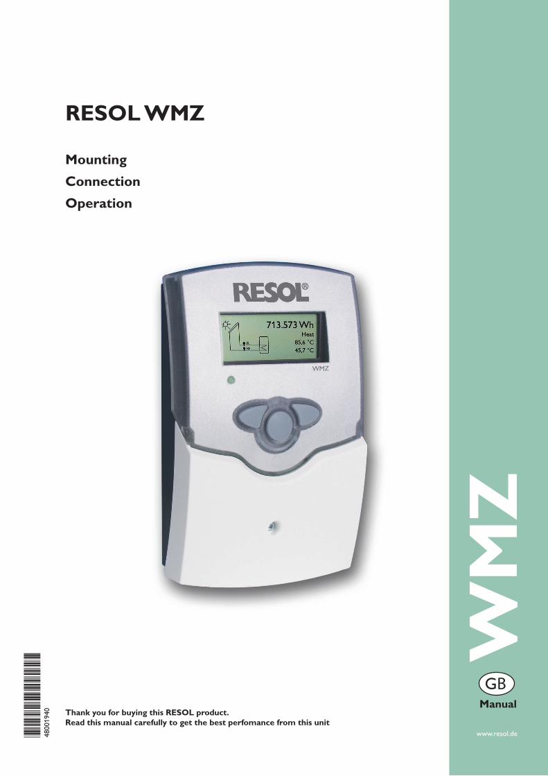
WMZ www.resol.de Thank you for buying this RESOL product. Read this manual carefully to get the best perfomance from this unit RESOL WMZ Mounting Connection Operation Manual *48001940* 48001940 B
Transcript
WM
Z
www.resol.de
Thank you for buying this RESOL product.Read this manual carefully to get the best perfomance from this unit
Please pay attention to the following safety advice in order to avoid danger and damage to people and property.
This product is to be used in accor-dance with its intended use only (see page 3).
Instructions
Attention should be paid to
- the statutory provisions for preven-tion of industrial accidents,
- the statutory provisions for environ-mental protection,
- the Health and Safety at Work Act 1974
- Part P of the Building Regulations 2005
- BS7671 Requirements for electrical installations and relevant safety re-gulations of DIN, EN, DVGW, TRGI, TRF and VDE.
These instructions are exclusively addressed to authorised skilled per-sonnel.
- Only qualified electricians should carry out electrical works.
- Initial installation must be effected by qualified personnel named by the manufacturer
Declaration of conformity
We, RESOL Elektronische Regelungen GmbH, D-45527 Hattingen, declare un-der our sole responsibility that our product WMZ complies with the following standards:
EN 55 014-1 EN 60 730-1
According to the regulations of the above directives, the product is labelled with :
2. Operation and function .....................................................................6 2.1 Buttons for adjustment .............................................................................6 2.2 Graphic display ...........................................................................................6 2.3 LED flashing codes .....................................................................................6
3. Determining the glycol-water ratio ..................................................7
4. Function ...............................................................................................7
5. Indication and adjustment channels .................................................8 5.1 Heat quantity ..............................................................................................8 5.2 Flow and return temperatures ...............................................................8 5.3 Volumetric flow rate .................................................................................8 5.4 Power ...........................................................................................................8 5.5 Antifreeze type ...........................................................................................9 5.6 Antifreeze ratio ..........................................................................................9 5.7 Flowmeter ...................................................................................................9 5.8 Volume/Impulse ..........................................................................................9 5.9 Subaddress ...................................................................................................9 5.10 Bus mode ...................................................................................................10 5.11 Bus master .................................................................................................10 5.12 Sensor offset .............................................................................................10
5.13 Reset ...........................................................................................................10 5.13 Language .....................................................................................................10
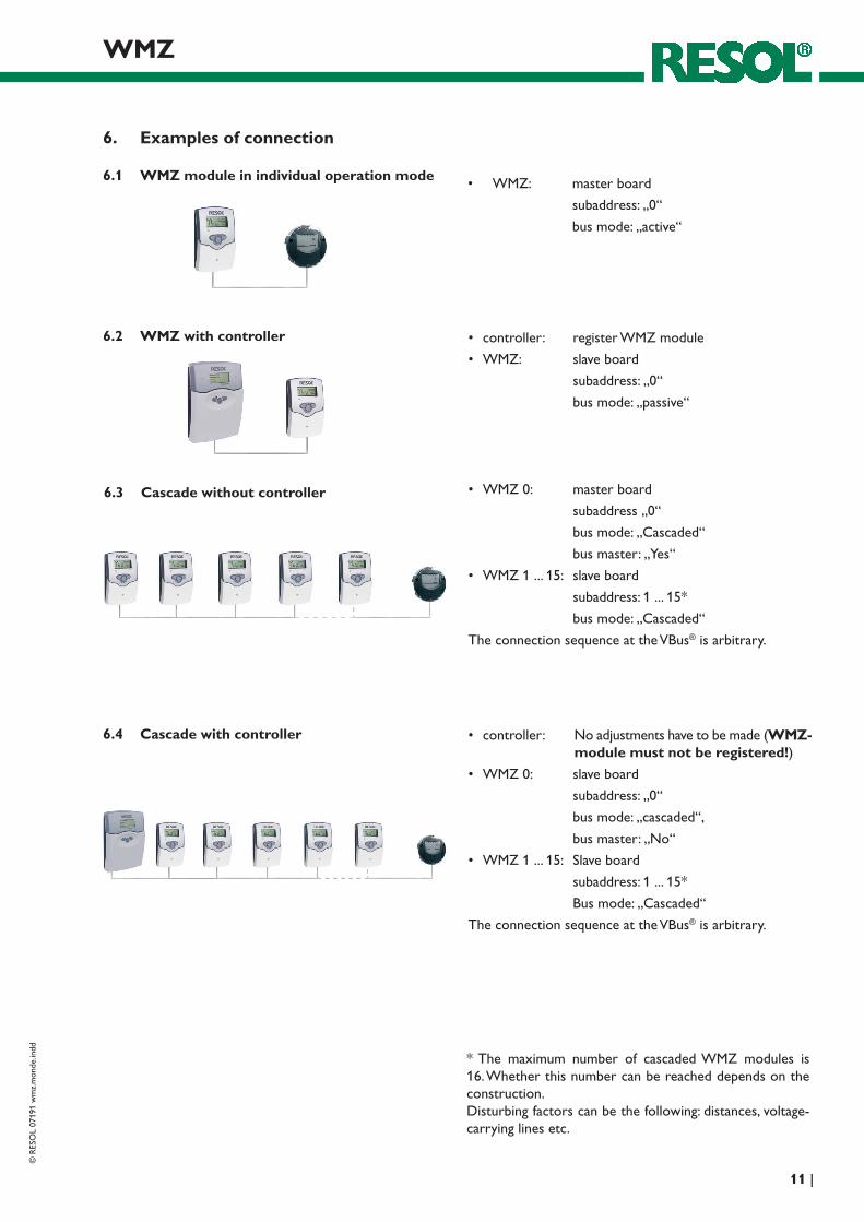
6. Examples of connection ...................................................................11
7. Tips for trouble shooting .................................................................12
Imprint ..............................................................................................16Errors an technical changes excepted.
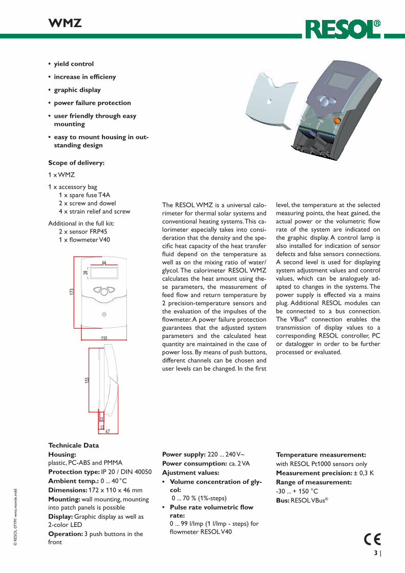
Technicale Data Housing: plastic, PC-ABS and PMMAProtection type: IP 20 / DIN 40050Ambient temp.: 0 ... 40 °CDimensions: 172 x 110 x 46 mmMounting: wall mounting, mounting into patch panels is possibleDisplay: Graphic display as well as 2-color LEDOperation: 3 push buttons in the front
Power supply: 220 ... 240 V~Power consumption: ca. 2 VAAjustment values:• Volumeconcentrationofgly-
1 x accessory bag 1 x spare fuse T4A 2 x screw and dowel 4 x strain relief and screw
Additional in the full kit: 2 x sensor FRP45 1 x flowmeter V40
Temperature measurement:with RESOL Pt1000 sensors onlyMeasurement precision: ± 0,3 KRange of measurement: -30 ... + 150 °CBus: RESOL VBus®
The RESOL WMZ is a universal calo-rimeter for thermal solar systems and conventional heating systems. This ca-lorimeter especially takes into consi-deration that the density and the spe-cific heat capacity of the heat transfer fluid depend on the temperature as well as on the mixing ratio of water/glycol. The calorimeter RESOL WMZ calculates the heat amount using the-se parameters, the measurement of feed flow and return temperature by 2 precision-temperature sensors and the evaluation of the impulses of the flowmeter. A power failure protection guarantees that the adjusted system parameters and the calculated heat quantity are maintained in the case of power loss. By means of push buttons, different channels can be chosen and user levels can be changed. In the first
level, the temperature at the selected measuring points, the heat gained, the actual power or the volumetric flow rate of the system are indicated on the graphic display. A control lamp is also installed for indication of sensor defects and false sensors connections. A second level is used for displaying system adjustment values and control values, which can be analoguely ad-apted to changes in the systems. The power supply is effected via a mains plug. Additional RESOL modules can be connected to a bus connection. The VBus® connection enables the transmission of display values to a corresponding RESOL controller, PC or datalogger in order to be further processed or evaluated.
Order noteThe calorimeter RESOL WMZ is available as a single device as well as a full kit with 2 Pt1000 sensors and a flowmeter RESOL V40.
• RESOLWMZ 135 303 53• RESOLWMZfullkit1
incl.V40-0,6 135 304 13• RESOLWMZfullkit2
incl.V40-1,5 135 304 23• RESOLWMZfullkit3
incl.V40-2,5 135 304 33• RESOLWMZfullkit4
incl.V40-3,5 135 304 43• RESOLWMZfullkit5
incl.V40-6,0 135 304 53• RESOLWMZfullkit6
incl.V40-10 135 304 63• RESOLWMZfullkit7
incl.V40-15 135 304 73
AccessoryRESOL refractometer set
For determining the concentration of glycol in the heat transfer medium
280 009 60
1 Unscrew the cross-head screw of the cover and re-move the cover from the housing.
2 Unscrew the two lateral srews of the transparent shield and remove the shield.
3 Pull out the board which has to be replaced carefully.Replace with new board.
Carry out assembly in reverse order.
Attention!When the WMZ is connected to a controller, the VBus master board has to be replaced with the VBus slave board!When several WMZ are cascaded and connected to a data-logger or PC (see p. 10), only the VBus master boards of the WMZs with the subaddress 1 or higher have to be replaced with the VBus slave boards!WarningSwitch-off power supply and disconnect from mains before opening the housing!
VBusboard
1 2
3
Electrostatic discharge can lead to damages of electronic components!
The device has to be located in a dry interior place. It is not suitable for installation in hazardous locations and should not be installed near to any electromagnetic fields. The de-vice must additionally be equipped with an all-polar gap of at least 3 mm or with a gap according to the valid installaton regulations, e.g. LS-switches or fuses. Please pay attention to a separate laying of the sensor lines and the power supply.
1. Unscrew the cross-head screw of the cover and remove it along with the cover from the housing.
2. Mark the upper fastening point on the underground and pre-assemble the enclosed dowel and screw.
3. Hang up the housing at the upper fastening point and mark the lower fastening point on the underground (hole-center distance 130 mm), afterwards fit the lower dowel.
4. Hang up the housing at the top and fasten it with the lower fastening screw
1. Installation Warning!Switch-off power supply and discon-nect from mains before opening the housing!
1.2 Electrical connection
The power supply of the controller must be carried out via an external power supply (last step!). The supply voltage must be 220 ... 240 Volt (50 ... 60 Hz). Flexible cables are to be attached to the housing using the enclosed strain reliefs and the respective screws.
In order to use the RESOL WMZ along with a flowmeter RESOL V40, the following connection is to be carried out (polarity of the separate terminals is arbitrary):1 / 2 = sensor S1 (feed flow temperature)3 / 4 = sensor S2 (return temperature)5 / 6 = flowmeter V409 / 10 = RESOL VBus®
The mains connection is carried out via the terminals:19 = neutral conductor N20 = line L12 / 13 / 14 = gound terminals
fuse
hanging
attachment
Electrostatic discharge can cause damage of elec-tronic components
Warning: high-voltaged components
A flowmeter RESOL V40 is used in order to determine the volumetric flow rate in the solar circuit. The installation is to be carried out taking the flow direction into consideration (consider direction indication on the flowmeter). In order to tranquilise the flow ratio, an inlet and an outlet distance of 30 cm in front of and behind the flowmeter have to be taken into account.
Note: Versions V40 0,6 to 2,5 are suited for horizontal as well as for vertical installation. Versions V40 3,5 to 15 are for horizontal installation only. In order to avoid a pressure sur-ge caused by cavitation in hydraulic systems, the heat trans-fer fluid should be filled in when it is cold, and de-aerators should be used. Pressure surge and turbulent flow ratios lead to damage of the sensitive measuring instruments.
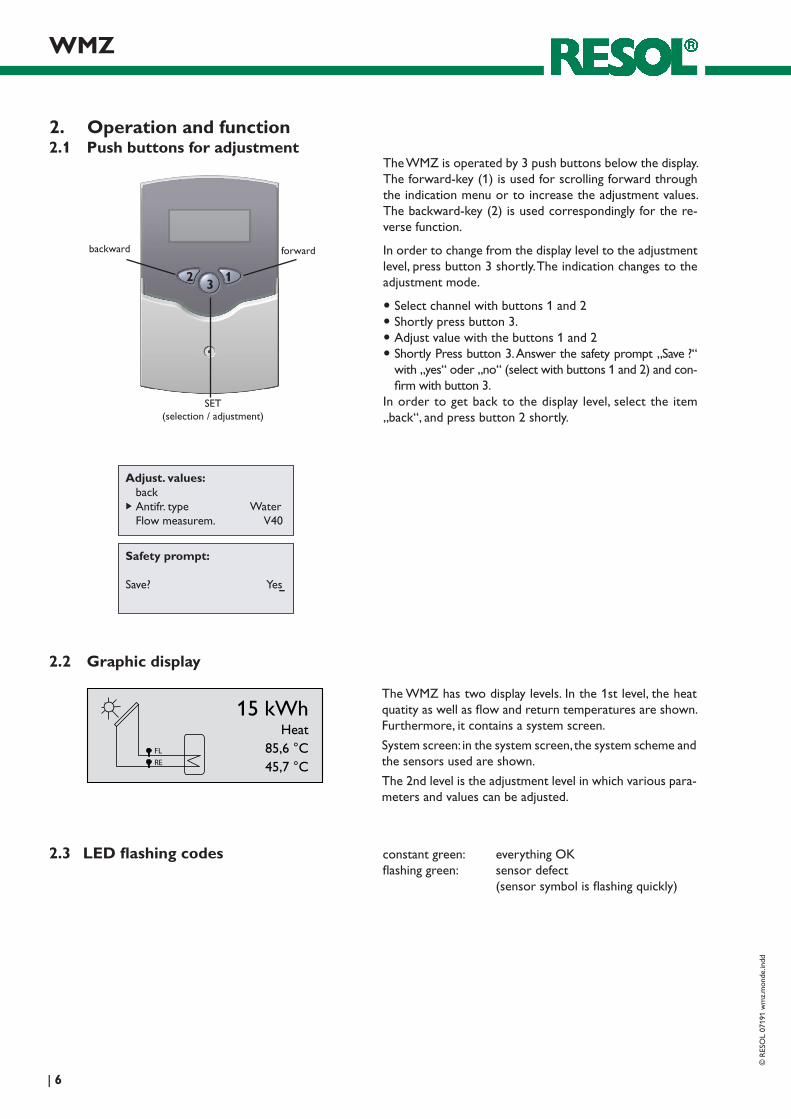
The WMZ has two display levels. In the 1st level, the heat quatity as well as flow and return temperatures are shown. Furthermore, it contains a system screen.
System screen: in the system screen, the system scheme and the sensors used are shown.
The 2nd level is the adjustment level in which various para-meters and values can be adjusted.
2. Operation and function2.1 Push buttons for adjustment
The WMZ is operated by 3 push buttons below the display. The forward-key (1) is used for scrolling forward through the indication menu or to increase the adjustment values. The backward-key (2) is used correspondingly for the re-verse function.
In order to change from the display level to the adjustment level, press button 3 shortly. The indication changes to the adjustment mode.
Select channel with buttons 1 and 2 Shortly press button 3. Adjust value with the buttons 1 and 2Shortly Press button 3. Answer the safety prompt „Save ?“
with „yes“ oder „no“ (select with buttons 1 and 2) and con-firm with button 3.
In order to get back to the display level, select the item „back“, and press button 2 shortly.
2.2 Graphic display
FL
RE
15 kWh Heat
85,6 °C 45,7 °C
constant green: everything OKflashing green: sensor defect (sensor symbol is flashing quickly)
2.3 LEDflashingcodes
Safety prompt: Save? Yes
Adjust. values: back Antifr. type Water Flow measurem. V40
Since the heat capacity of the heat transfer fluid depends on the concentration of glycol, the proportion of the gly-col/water-mixture has to be determined first.
Determining the ratio for known volumes:
If the volumes of water and glycol in the system are known, the value in vol. % is calculated as follows:
Vol%=(VG:(VW+VG))x100 VG: volume of glycol
VW: volume of water
Example: if 15 liters of water and 20 liters of glycol are used in the solar circuit, then follows:
Vol % = (20 : (15 + 20)) x 100) = 57
Determining the ratio for unknown volumes:
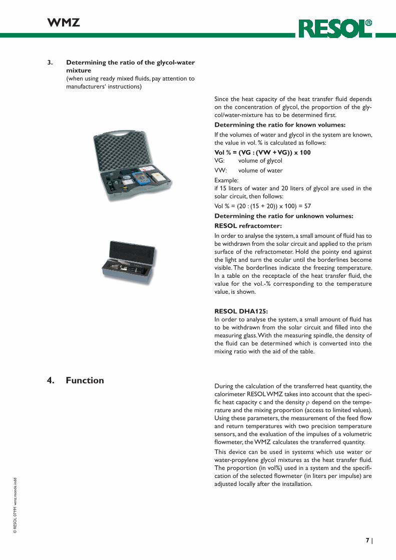
RESOL refractomter:
In order to analyse the system, a small amount of fluid has to be withdrawn from the solar circuit and applied to the prism surface of the refractometer. Hold the pointy end against the light and turn the ocular until the borderlines become visible. The borderlines indicate the freezing temperature. In a table on the receptacle of the heat transfer fluid, the value for the vol.-% corresponding to the temperature value, is shown.
RESOL DHA125: In order to analyse the system, a small amount of fluid has to be withdrawn from the solar circuit and filled into the measuring glass. With the measuring spindle, the density of the fluid can be determined which is converted into the mixing ratio with the aid of the table.
3. Determining the ratio of the glycol-water mixture (when using ready mixed fluids, pay attention to manufacturers‘ instructions)
4. FunctionDuring the calculation of the transferred heat quantity, the calorimeter RESOL WMZ takes into account that the speci-fic heat capacity c and the density r depend on the tempe-rature and the mixing proportion (access to limited values). Using these parameters, the measurement of the feed flow and return temperatures with two precision temperature sensors, and the evaluation of the impulses of a volumetric flowmeter, the WMZ calculates the transferred quantity.
This device can be used in systems which use water or water-propylene glycol mixtures as the heat transfer fluid. The proportion (in vol%) used in a system and the specifi-cation of the selected flowmeter (in liters per impulse) are adjusted locally after the installation.
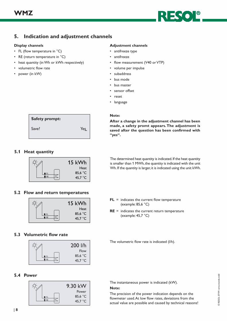
FL = indicates the current flow temperature (example: 85,6 °C)
RE = indicates the current return temperature (example: 45,7 °C)
The determined heat quantity is indicated. If the heat quantity is smaller than 1 MWh, the quantity is indicated with the unit Wh. If the quantity is larger, it is indicated using the unit kWh.
The volumetric flow rate is indicated (l/h).
The instantaneous power is indicated (kW).
Note:
The precision of the power indication depends on the flowmeter used. At low flow rates, deviations from the actual value are possible and caused by technical reasons!
Safety prompt: Save? Yes
Note:
After a change in the adjustment channel has been made,asafetypromtappears.Theadjustmentissavedafterthequestionhasbeenconfirmedwith“yes“.
Adjust. values: back Antifr. type Water Flow measurem. V40
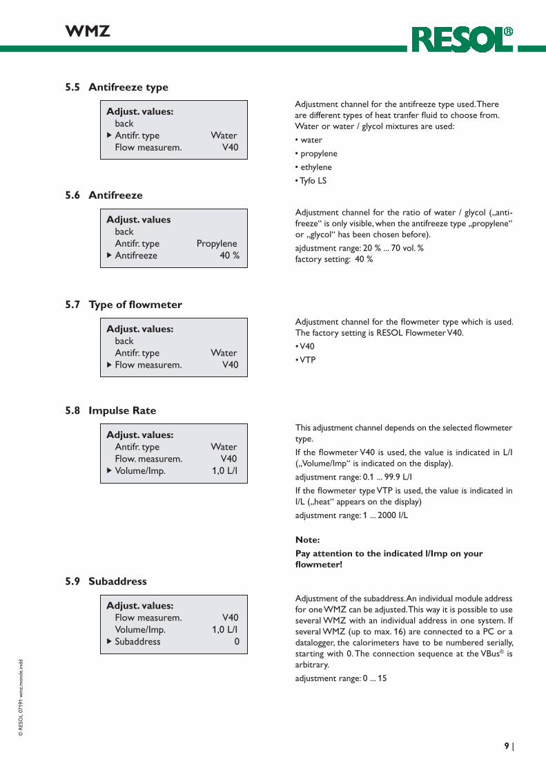
5.5 Antifreeze type
Adjustment channel for the antifreeze type used. There are different types of heat tranfer fluid to choose from. Water or water / glycol mixtures are used:
•water
•propylene
•ethylene
•TyfoLS
Adjust. values back Antifr. type Propylene Antifreeze 40 %
5.6 Antifreeze
Adjustment channel for the ratio of water / glycol („anti-freeze“ is only visible, when the antifreeze type „propylene“ or „glycol“ has been chosen before).
Adjustment of the subaddress. An individual module address for one WMZ can be adjusted. This way it is possible to use several WMZ with an individual address in one system. If several WMZ (up to max. 16) are connected to a PC or a datalogger, the calorimeters have to be numbered serially, starting with 0. The connection sequence at the VBus® is arbitrary.
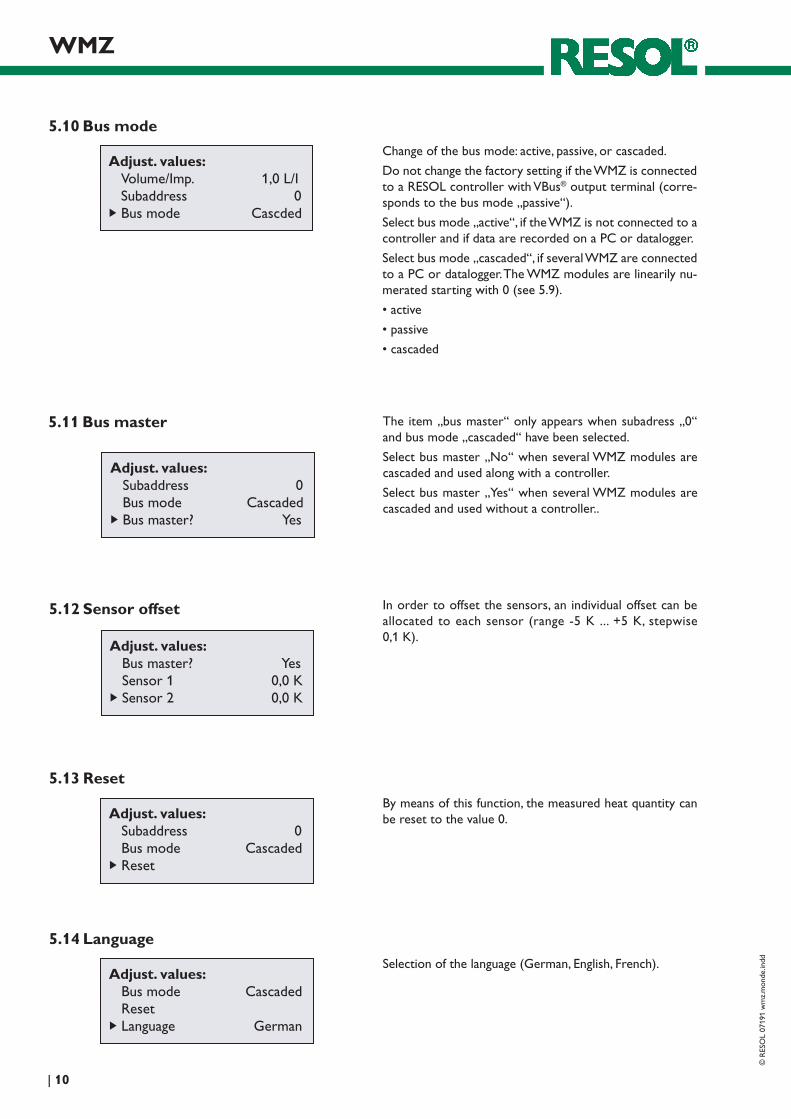
6.2 WMZ with controller • controller: registerWMZmodule
• WMZ: slaveboard
subaddress: „0“
bus mode: „passive“
6.3 Cascade without controller • WMZ0: masterboard
subaddress „0“
bus mode: „Cascaded“
bus master: „Yes“
• WMZ1...15: slaveboard
subaddress: 1 ... 15*
bus mode: „Cascaded“
The connection sequence at the VBus® is arbitrary.
6.4 Cascade with controller • controller: Noadjustmentshavetobemade(WMZ-module must not be registered!)
• WMZ0: slaveboard
subaddress: „0“
bus mode: „cascaded“,
bus master: „No“
• WMZ1...15: Slaveboard
subaddress: 1 ... 15*
Bus mode: „Cascaded“
The connection sequence at the VBus® is arbitrary.
* The maximum number of cascaded WMZ modules is 16. Whether this number can be reached depends on the construction.Disturbing factors can be the following: distances, voltage- carrying lines etc.
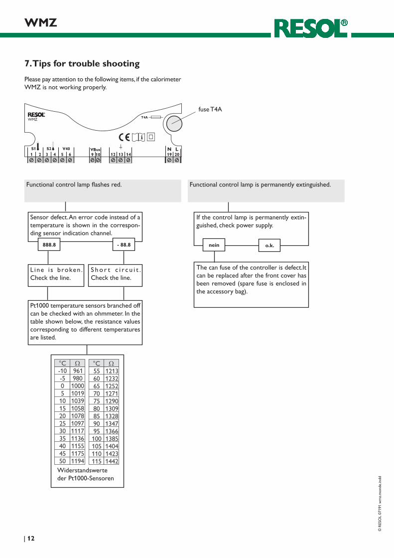
Functional control lamp is permanently extinguished.
If the control lamp is permanently extin-guished, check power supply.
nein
The can fuse of the controller is defect.It can be replaced after the front cover has been removed (spare fuse is enclosed in the accessory bag).
Functional control lamp flashes red.
Sensor defect. An error code instead of a temperature is shown in the correspon-ding sensor indication channel.
- 88.8888.8
L ine i s b roken . Check the line.
S h o r t c i r c u i t . Check the line.
Pt1000 temperatur e sen sors branched off can be checked with an ohmmeter. In the table shown below, the resistance values corresponding to different temperatures are listed.
Please pay attention to the following items, if the calorimeter WMZ is not working properly.
Reprinting / copyingThis mounting- and operation manual including all parts is copyrighted. Another use outside the copyright requires the approval of RESOL - Elektronische Regelungen GmbH. This especially applies for copies, translations, micro films and the storage into electronic systems. Editor: RESOL - Elektronische Regelungen GmbH
Important notice:We took a lot of care with the texts and drawings of this manual and to the best of our knowledge and consent. As faults can never be excluded, please note: Your own calcu-lations and plans, under consideration of the current stan-dards and DIN-directions should only be basis for your projects. We don´t offer a guarantee for the completeness of the drawings and texts of this manual - they only repre-sent some examples. They can only be used at your own risk. No liability is assumed for incorrect, incomplete or false information and the resulting damages.