39
MOUSETRAP Ultra-High-Speed Transition-Signaling Asynchronous Pipelines Montek Singh & Steven M. Nowick Department of Computer Science Columbia University, New York, NY 10027 2001 IEEE
| Date post: | 30-Dec-2015 |
| Category: |
Documents |
| Upload: | brianna-manning |
| View: | 215 times |
| Download: | 0 times |

MOUSETRAPUltra-High-Speed Transition-Signaling Asynchronous Pipelines
Montek Singh & Steven M. Nowick
Department of Computer ScienceColumbia University, New York, NY 10027
2001 IEEE

Agenda
Review Introduction MOUSETRAP Preliminary Experiment Results Conclusions
Review Synchronous pipeline
Wave pipeline Clock-delayed domino Skew-tolerant domino Self-resetting circuits
Asynchronous pipeline Micropipeline GasP IPCMOS

Asynchronous circuit’s benefits
No clock skew problem Low power consumption Faster speed (average case) Reduce global timing issues Avoid variations in fabrication,temperatu
re,…etc. Low EMI & Noise ………

Low Power Consumption On high-performance chips
Clock power consumption is a significant proportion of total power consumption.
Gated clocks reduce the wastage Make clock skew worse Incur some power cost
All parts of the clocked circuits run the same frequency

Performance
Synchronous design must be toleranced for worst case conditions Fabrication, temperature, voltage, data v
alues, Clock skew Asynchronous circuits self-adjust to th
e operating and data conditions
Agenda
Review Introduction MOUSETRAP Preliminary Experiment Results Conclusions

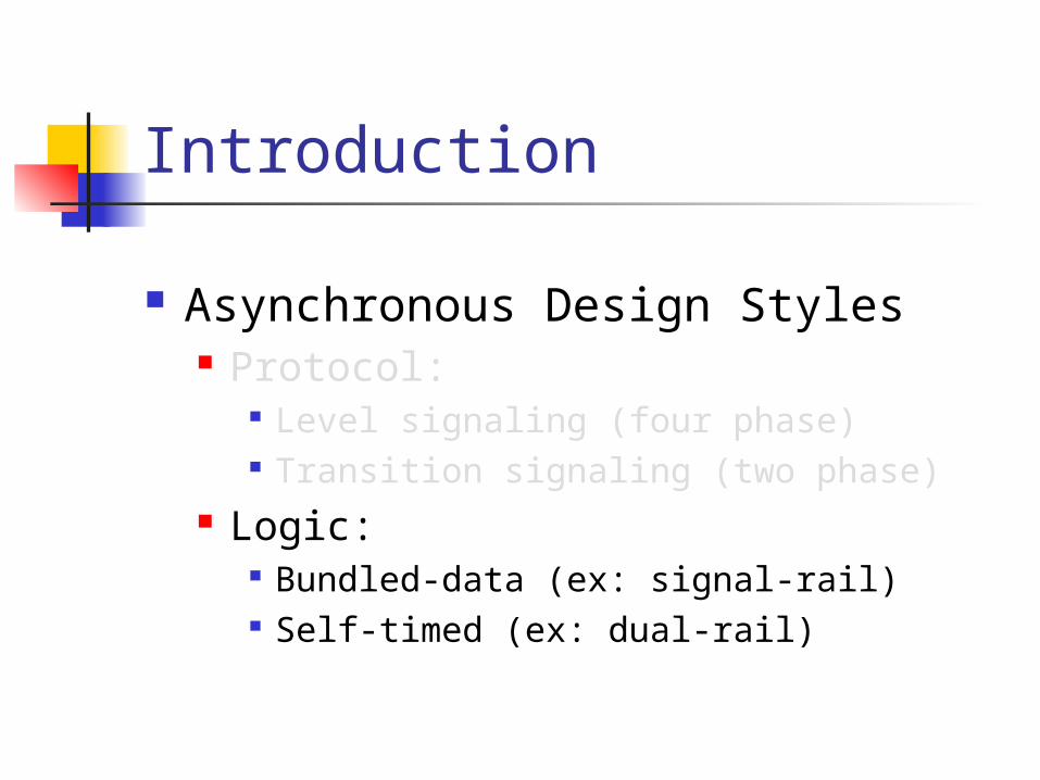
Introduction
Asynchronous Design Styles Protocol:
Level signaling (four phase) Transition signaling (two phase)
Logic: Bundled-data (ex: signal-rail) Self-timed (ex: dual-rail)
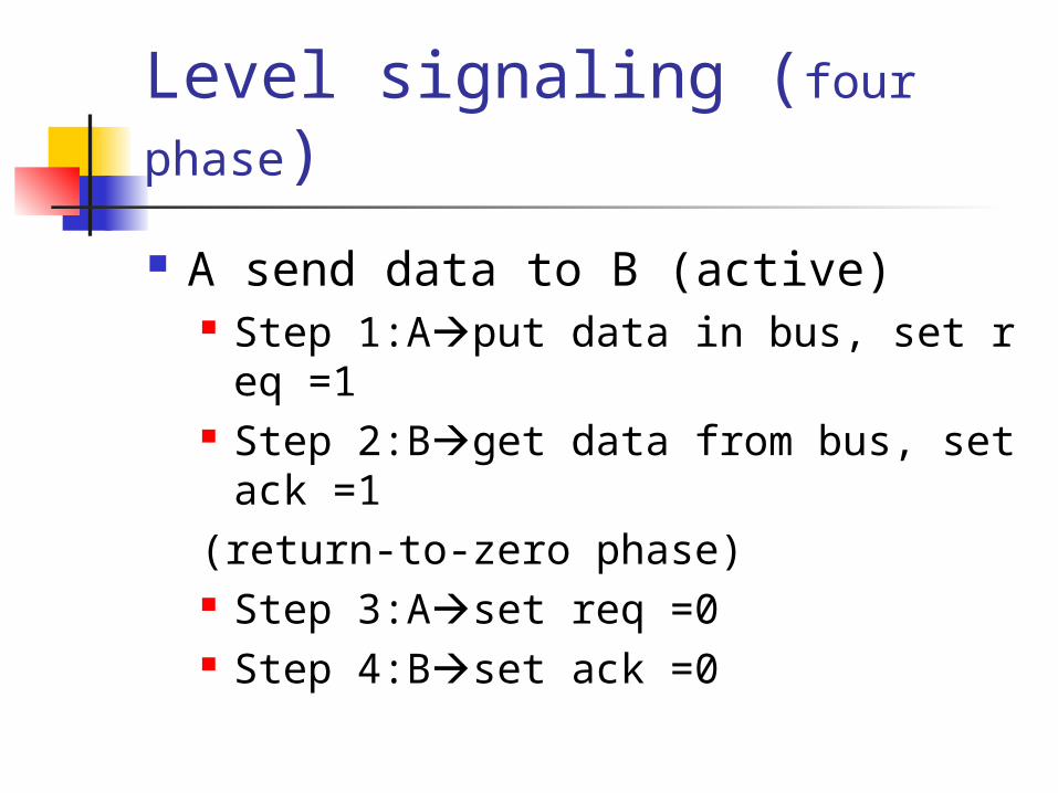
Level signaling (four phase)
A send data to B (active) Step 1:Aput data in bus, set req =1 Step 2:Bget data from bus, set ack =1(return-to-zero phase) Step 3:Aset req =0 Step 4:Bset ack =0

Transition signaling (two
phase)
A send data to B (active) Step 1:Aput data in bus, set req =1 Step 2:Bget data from bus, set ack =1 Step 3:A put data in bus , set req =0 Step 4:B get data from bus, set ack =0
Introduction
Asynchronous Design Styles Protocol:
Level signaling (four phase) Transition signaling (two phase)
Logic: Bundled-data (ex: signal-rail) Self-timed (ex: dual-rail)
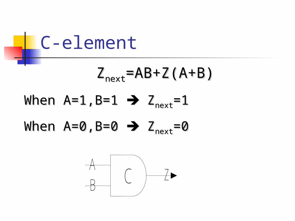
C-element
ZZnextnext=AB+Z(A+B)=AB+Z(A+B)
When A=1,B=1 When A=1,B=1 Z Znextnext=1=1
When A=0,B=0 When A=0,B=0 Z Znextnext=0=0
CAB
Z

Micropipeline 4-phase latch FIFO
C C C
latch latch latch
Data
req
ack

Bundled-data
C C C
latch latch latch
DataFunction Unit
Function Unit

Self-timed
Generate Completion-Detection signal
Delay-Insensitive (DI) Coding ex:dual-rail coding (two phase coding)
00 -> invalid value 01 -> 0 10 -> 1 11 -> no use

Self-timed (dual-rail coding)
C C
FFSR latch(decoder)
DataFunction Unit
DI-encode
A1A2
B1B2
CDS
FF

Performance Comparison of Asynchronous Adders Mark A. Franklin & Tienyo Pan
Agenda
Review Introduction MOUSETRAP Preliminary Experiment Results Conclusions

Mousetrap
Minimal-Overhead Ultrahigh-SpEed Transition-signaling Asynchronous Pipeline

MOUSETRAP-FIFO
Latch delay is 110 psXNOR delay is 65 ps
data data data data
latch
Reqn-1 Reqn Reqn+1 Reqn+2
En En En
latch latch

MOUSETRAPwith logic (bundled data)
data data data
latch
Reqn-1 Reqn Reqn+1 Reqn+2
En En En
latch latch
functiondata
function

Bundled data
Bundled data scheme: Reqn must arrive at stage N after the data i
nputs to that stage have stabilized. Worst-case delay Allow circuits to have hazards

Delay Buffer
Inverter chain A chain of transmission gates Duplicate the worst-case critical
path More accurate delay More area-expensive

Timing-forward latency
icLt ttL log
data data data
latch
Reqn-1 Reqn Reqn+1 Reqn+2
En En En
latch latch
functiondata
function

Timing-Cycle time
XNORicLt tttL log2
data data data
latch
Reqn-1 Reqn Reqn+1 Reqn+2
En En En
latch latch
functiondata
function
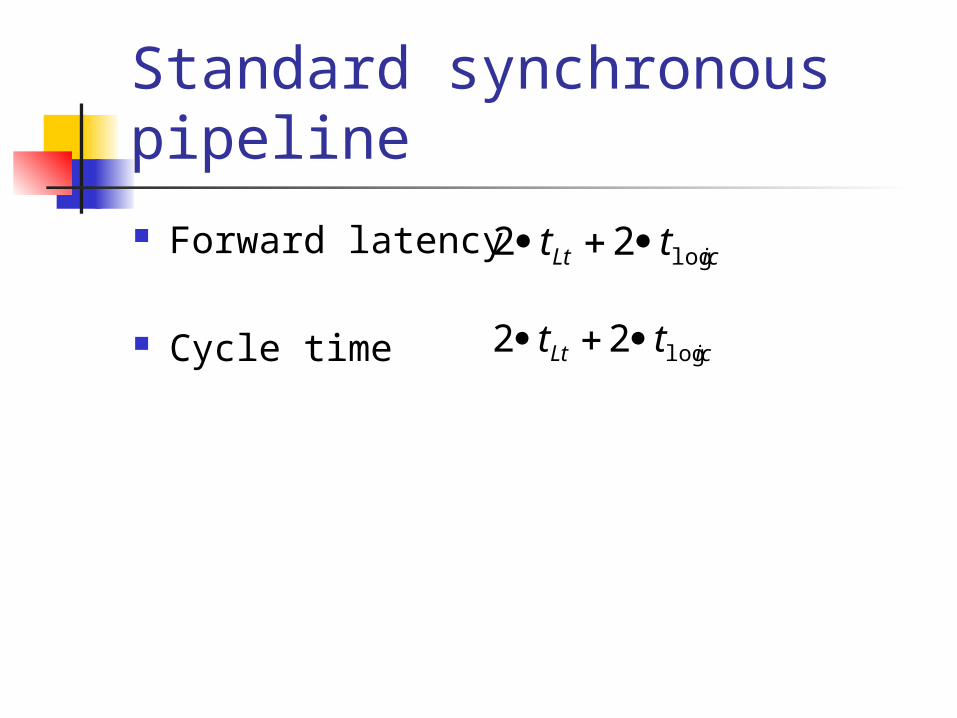
Standard synchronous pipeline Forward latency
Cycle time
icLt tt log22
icLt tt log22

MOUSETRAP-Setup time
data data data data
latch
Reqn-1 Reqn Reqn+1 Reqn+2
En En En
latch latch
sunXNORreqreq tttnn
1
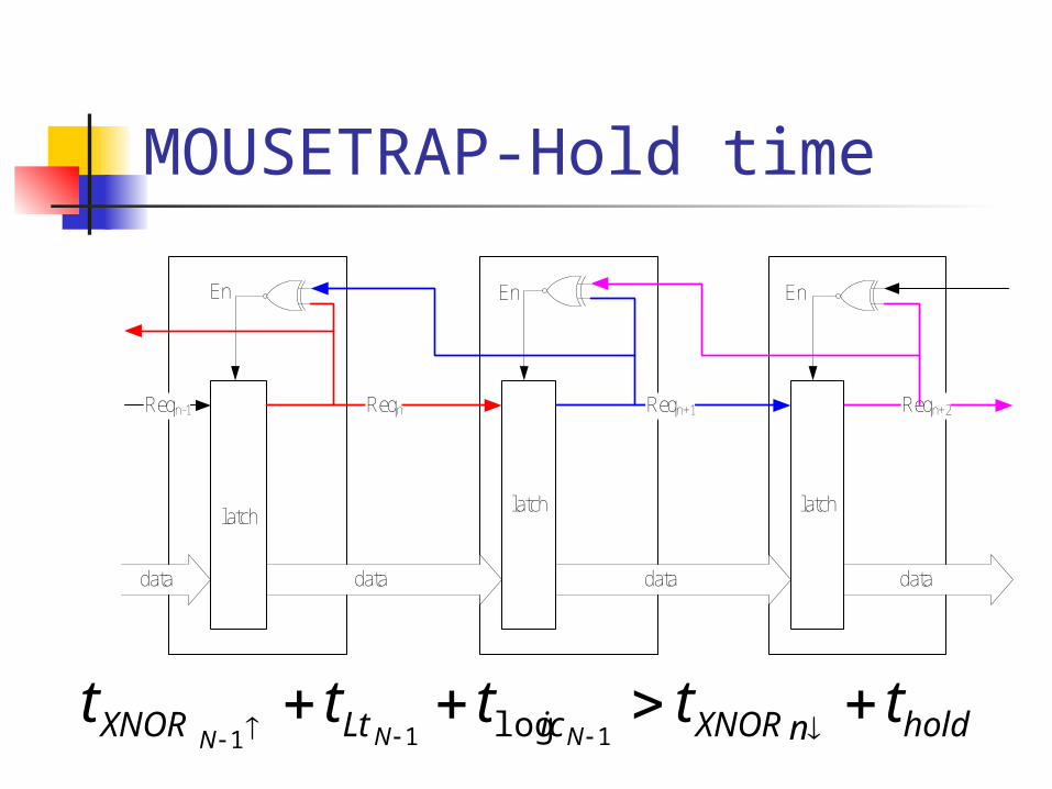
MOUSETRAP-Hold time
data data data data
latch
Reqn-1 Reqn Reqn+1 Reqn+2
En En En
latch latch
holdnXNORicLtXNOR tttttNNN
111 log
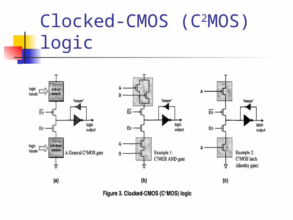
Clocked-CMOS (C2MOS) logic

C2MOS’s benefits
Smaller delay Smaller area Lower power consumption

MOUSETRAP- C2MOS
Forward latency Cycle time
MOSCMOSCtL 22
XNORMOSCMOSCttT 22 2
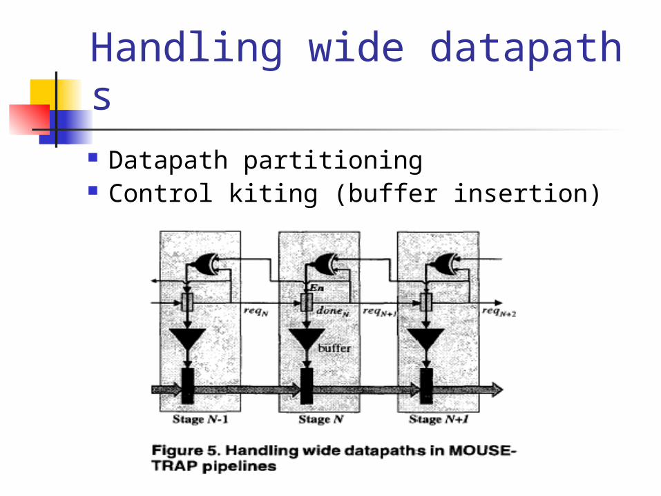
Handling wide datapaths Datapath partitioning Control kiting (buffer insertion)

Optimization
Sliding door Change MOS’s width (lower
)
XNORt

Non-Linear Pipeline-fork
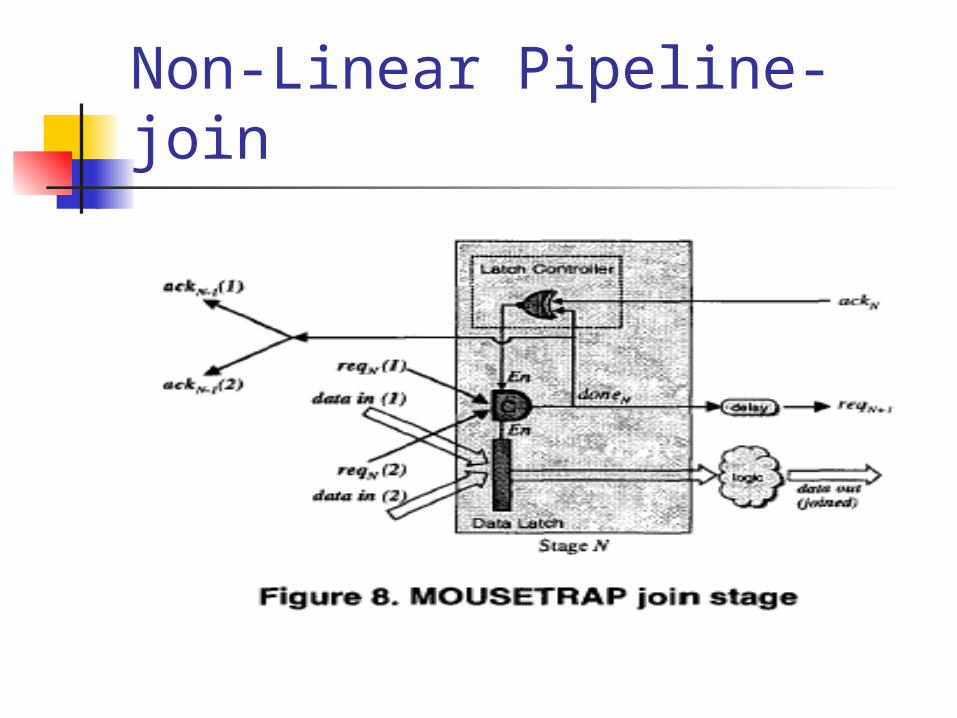
Non-Linear Pipeline-join

experiment 0.25μm TSMC
2.5v , 300k A pass-gate implementation of an XNOR/XOR A standard 6 transistor pass-gate dynamic D-lat
ch 0.6μm HP
3.3v ,300K A pass-gate implementation of an XNOR/XOR Clocked-CMOS style latch
10 stage, 16-bit datapath pre-layout simulation (HSPICE)

result

Conclusions
Use small & fast latches Low Latch controller overhead(XNOR) Transition-signaling protocol
(efficient & concurrent) Without complex timing & design effort Variable-speed environment(elasticity)

comparison
IPCMOS (asynchronous interlocked pipelined CMOS) 3.3~4.5GHz IBM 0.18μm Post-layout simulation


