Inter-noise 2014 Page 1 of 10 Moving boundary similarity method and its application on ship structural borne noise prediction Fu-zhen PANG 1 ; Xu-hong MIAO 2 ; Dong TANG 3 ; Hong-bao SONG 4 1 Naval Academy of Armament, Beijing 100161, China 2 Naval Academy of Armament, Beijing 100161, China 3 College of Shipbuilding Engineering, Harbin Engineering University, Harbin 150001, China 4 College of Shipbuilding Engineering, Harbin Engineering University, Harbin 150001, China ABSTRACT Based on the principle of structural dynamics, the unitary of exciting force and moving boundary condition is proved by vibration analyzing of an equipment-base system. By constructing “virtual force” to keep the consistency of moving boundaries of structure with dynamic parameters locally unknown, moving boundary similarity method (MBSM) is proposed to get structural dynamic response of given moving boundary conditions with structural dynamic parameters locally unknown. The effectiveness of MBSM is also verified. On that basis, MBSM is applied to the study of ship’s underwater vibration and noise radiation. The underwater noise radiation characteristic of a ship is analyzed. Result shows that the underwater vibration and sound radiation of a ship is highly related with location and frequency of excitations. On one hand, ship structural borne noise radiation is mainly concentrated in the vicinity of excitation of the middle and aft region of ship, followed by aft and bow. On the other hand, the underwater noise radiation is more uniformly distributed along the ship length in low frequency band, while the inhomogeneity and directivity gradually increases as excitation frequency increases. Keywords: Structural Dynamic Analysis, Moving Boundary Similarity Method, Underwater Radiated Noise I-INCE Classification of Subjects Number(s): 54.3 1. INTRODUCTION Structural dynamic response predictions under given forces have been widely discussed in structural dynamics, while cases with moving boundary conditions (with given velocity /acceleration, for an example) are rarely mentioned, not even for the cases with dynamic parameters locally unknown. However, there are a large number of engineering practices for this kind of demand. Problems of structure dynamics prediction of ships by measuring the vibration of pedestals or base of power equipment with parameters unknown often occur in ship structure dynamics research f ield. Riser’s structure dynamics and strength are expected by surveying the vibration at junctions of platform and risers in marine engineering field. Based on modal superposition and wave propagation theory, structural dynamics analysis methods such as theoretical method, Finite Difference Method (FDM), Finite Element Method (FEM), Boundary Element Method (BEM) and Statistical Energy Analysis Method (SEA) are developed to predict dynamic response of structures under given excitations, which meet the general requirements of theoretical research and engineering applications [1-8] . In the dynamic analysis of structures under given moving boundary conditions, researchers carry out structural dynamic analysis with analytical method or numerical simulations by transforming given moving boundary conditions into exciting force. For an instance, when predicting vibration caused by excitations from an equipment, by measuring vibration acceleration and impedance at each end of isolators, a transform method from vibration acceleration into exciting force of the equipment is established, which makes the dynamic 1 [email protected]2 [email protected]3 [email protected]4 [email protected]
Transcript
Inter-noise 2014 Page 1 of 10
Moving boundary similarity method and its application on ship
structural borne noise prediction
Fu-zhen PANG1; Xu-hong MIAO
2; Dong TANG
3; Hong-bao SONG
4
1 Naval Academy of Armament, Beijing 100161, China
2 Naval Academy of Armament, Beijing 100161, China
3 College of Shipbuilding Engineering, Harbin Engineering University, Harbin 150001, China
4 College of Shipbuilding Engineering, Harbin Engineering University, Harbin 150001, China
ABSTRACT
Based on the principle of structural dynamics, the unitary of exciting force and moving boundary condition is
proved by vibration analyzing of an equipment-base system. By constructing “virtual force” to keep the
consistency of moving boundaries of structure with dynamic parameters locally unknown, moving boundary
similarity method (MBSM) is proposed to get structural dynamic response of given moving boundary
conditions with structural dynamic parameters locally unknown. The effectiveness of MBSM is also verified.
On that basis, MBSM is applied to the study of ship’s underwater vibration and noise radiation. The
underwater noise radiation characteristic of a ship is analyzed. Result shows that the underwater vibration
and sound radiation of a ship is highly related with location and frequency of excitations. On one hand, ship
structural borne noise radiation is mainly concentrated in the vicinity of excitation of the middle and aft
region of ship, followed by aft and bow. On the other hand, the underwater noise radiation is more uniformly
distributed along the ship length in low frequency band, while the inhomogeneity and directivity gradually
analysis of ship structure under given moving boundary conditions from the equipment possible [9-10]
.
However, it is noteworthy that, when transforming the vibration of the equipment into the exciting
forces, both the vibration acceleration and impedance at each end of isolator should be measured [11-15]
.
If the impedance of the isolator is unknown, the transformation becomes impossible. Therefore, it is
still hard to get the dynamic response of a structure under given moving boundary conditions with
dynamic parameters locally unknown.
Actually, according to structural dynamics, boundary conditions of a structure can be expressed
either in the form of displacement or force, which is accordant in essence. Taking advantage of the
unity of displacement boundary conditions and mechanical boundary conditions, the displacement
boundary conditions can be transformed into mechanical boundary conditions, which can effectively
reduce the cost and errors caused by transformation.
Based on the theory of structural dynamics, the unity of displacement boundary conditions and
mechanical boundary conditions is proved. By constructing a virtual force to keep the consistence of
boundary conditions; the Moving Boundary Similarity Method (MBSM) is proposed to get the
structural dynamic response by given moving boundary conditions with parameters locally unknown.
Effectiveness and validations are also presented. On that basis, MBSM is applied to the analysis of
underwater vibration and noise radiation of a ship. Characteristic of underwater noise radiation of the
ship is also discussed.
2. MBSM IN STRUCTURAL DYNAMIC ANALYSIS
2.1 The Method to Calculate the Modal Loss Factor of Composite Plate Structure
In the field of structural dynamics analysis, a given moving boundary conditions can be expressed
in the form of mechanical boundary conditions. And also a given mechanical boundary conditions
can be presented as moving boundary conditions as well, which indicates that the moving boundary
conditions and mechanical boundary conditions are equivalent. This principle not only suits for
simple structures, but also for complex ones. To illustrate the correctness of the principle, a two DOF
vibration model of an equipment-base system is established.
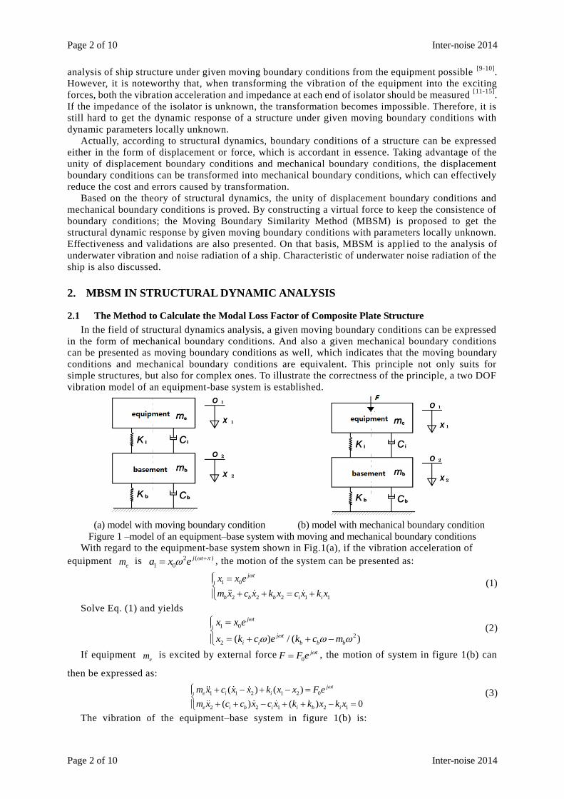
(a) model with moving boundary condition (b) model with mechanical boundary condition
Figure 1 –model of an equipment–base system with moving and mechanical boundary conditions
With regard to the equipment-base system shown in Fig.1(a), if the vibration acceleration of
equipment em is 2 ( )
1 0
j ta x e , the motion of the system can be presented as:
1 0
2 2 2 1 1
j t
b b b i i
x x e
m x c x k x c x k x
(1)
Solve Eq. (1) and yields
1 0
2
2 ( ) / ( )
j t
j t
i i b b b
x x e
x k c e k c m
(2)
If equipment em is excited by external force
0
j tF F e , the motion of system in figure 1(b) can
then be expressed as:
1 1 2 1 2 0
2 2 1 2 1
( ) ( )
( ) ( ) 0
j t
e i i
e i b i i b i
m x c x x k x x F e
m x c c x c x k k x k x
(3)
The vibration of the equipment–base system in figure 1(b) is:
Inter-noise 2014 Page 3 of 10
Inter-noise 2014 Page 3 of 10
1 1
2 2
/
/
j t
j t
x D e D
x D e D
(4)
Where
2
2
( )
( ) ( )
i e i i i
i i b i b i b
k m jc k jcD
k jc k k m j c c
,
0
1 2
( )
0 ( )
i i
b i b i b
F k jcD
k k m j c c
,
2
0
2( ) 0
i e i
i i
k m jc FD
k jc
Equals Eq.(2) and Eq.(4) and yields
0 0 1/F Dx D (5)
Eq. (5) shows that, if exerting force 0 0 1/j t j tF F e Dx e D on equipment
em of the model shown
in Figure 1(b), the vibration of the system in Figure 1(a) and Figure 1(b) will be identical, which
proves that the moving boundary conditions can be presented in the form of the correspond ing
mechanical boundary conditions.
Similarly, if the displacement 0x is unknown, equals Eq. (2) and Eq. (4), and yields:
0 0 1 /x F D D (6)
That is, by keeping the displacement of equipment me in Fig.1(a) equals to 1 1 0 /j tx D F e D , the
vibration of the system in Fig.1(b) will be identical, which indicates that mechanical boundary
conditions can be also presented in the form of the corresponding moving boundary conditions . Hence the moving boundary conditions and the mechanical boundary conditions are accordant.
2.2 Theory of MBSM
If dynamic parameters of a system are given, structural dynamic analysis can be performed by
transforming the moving boundary conditions into the corresponding exciting forces with the method
proposed in chapter 2.1. However, it’s still hard to determine the exciting force if dynamic
parameters of the system are locally unknown.
To solve the problem caused by uncertainty of dynamic parameters of the system, a similar
system should be established. Then, by ensuring consistency of the similar system and the original
one, the virtual force, which is required for dynamic analysis of the system, is created. Therefore, the
actual vibration response of the original system can be obtained from the analysis of the similar
system.
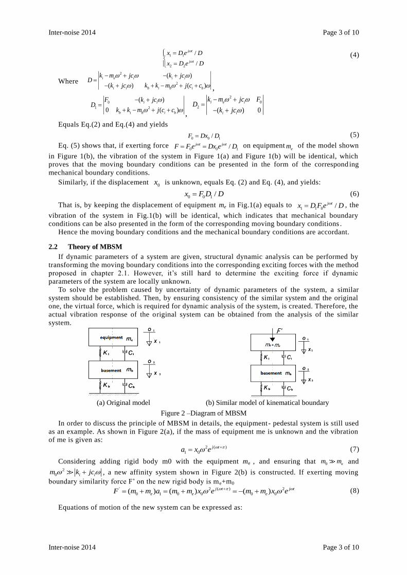
(a) Original model (b) Similar model of kinematical boundary
Figure 2 –Diagram of MBSM
In order to discuss the principle of MBSM in details, the equipment- pedestal system is still used
as an example. As shown in Figure 2(a), if the mass of equipment me is unknown and the vibration
of me is given as:
2 ( )
1 0
j ta x e (7)
Considering adding rigid body m0 with the equipment me , and ensuring that 0 em m and 2
0 i im k jc , a new affinity system shown in Figure 2(b) is constructed. If exerting moving
boundary similarity force F’ on the new rigid body is me+m0
' 2 ( ) 2
0 1 0 0 0 0( ) ( ) ( )j t j t
e e eF m m a m m x e m m x e (8)
Equations of motion of the new system can be expressed as:
Page 4 of 10 Inter-noise 2014
Page 4 of 10 Inter-noise 2014
2
0 1 1 2 1 2 0 0
0 2 2 1 2 1
( ) ( ) ( ) ( )
( ) ( ) ( ) 0
j t
e i i e
e i b i i b i
m m x c x x k x x m m x e
m m x c c x c x k k x k x
(9)
The response of the new system shown in Figure 2(b) is
1 1
2 2
/
/
j t
j t
x E e E
x E e E
(10)
Where 2
0
2
( ) ( )
( ) ( )
i e i i i
i i b i b i b
k m m jc k jcE
k jc k k m j c c
,
2
0 0
1 2
( ) ( )
0 ( )
e i i
b i b i b
m m x k jcE
k k m j c c
,
2 2
0 0
2
( )
( ) 0
i e i e
i i
k m jc m m xE
k jc
Since 0 em m and 2
0 i im k jc , thus
2 2
01 0 02 2 2
0
[ ( ) ]( )
[ ( ) ][ ( ) ] ( )
j t j tb i b i b e
b i b i b i e i i i
k k m j c c m mx x e x e
k k m j c c k m m jc k jc
(11)
2
02 0 22 2 2
0
( )( )/
[ ( ) ][ ( ) ] ( )
j t j ti i e
b i b i b i e i i i
k jc m mx x e D e D
k k m j c c k m m jc k jc
(12)
Comparing Eq.(2) and Eq.(11)~(12), it can be seen that the dynamic response of the affinity system
and the original one are the same, which indicates that MBS is feasible in structural dynamics analysis .
2.3 Basic Steps of MBSM
From the discussion mentioned above, it can be seen that whether parameters of a
system are known or not, if the moving boundary conditions of the system is given, the
dynamic response of the system can be derived by transforming the moving boundary
conditions into the corresponding mechanical boundary conditions. When parameters of
a system are unknown, the moving boundary conditions can be transformed into the
corresponding mechanical boundary conditions by the following steps (1) Construct a rigid body with great mass
0m on the moving boundary of the system, and ensure that
0 em m and 2
0 i im k jc .
(2) Calculate moving boundary similarity force 0 0( )eF m m a m a according to the mass m0 and
vibration acceleration a of rigid body.
(3) Apply moving boundary similarity force 0F m a on the rigid body m0.
What is worth noting here is that, MBSM is only valid on the premises that0 em m and
2
0 i im k jc . And the greater the mass of the rigid body is, the higher the calculation accuracy will be.
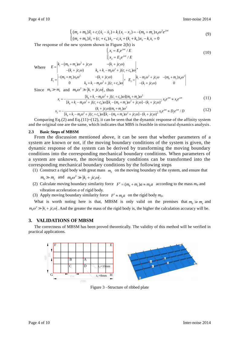
3. VALIDATIONS OF MBSM
The correctness of MBSM has been proved theoretically. The validity of this method will be verified in
practical applications.
AB
C D
EF
G Ht =8mm1
2t =10mm
Figure 3 –Structure of ribbed plate
Inter-noise 2014 Page 5 of 10
Inter-noise 2014 Page 5 of 10
0.0001
0.001
0.01
0.1
1
0 20 40 60 80 100
Accleration/
m/s^2
Frequency /Hz
original
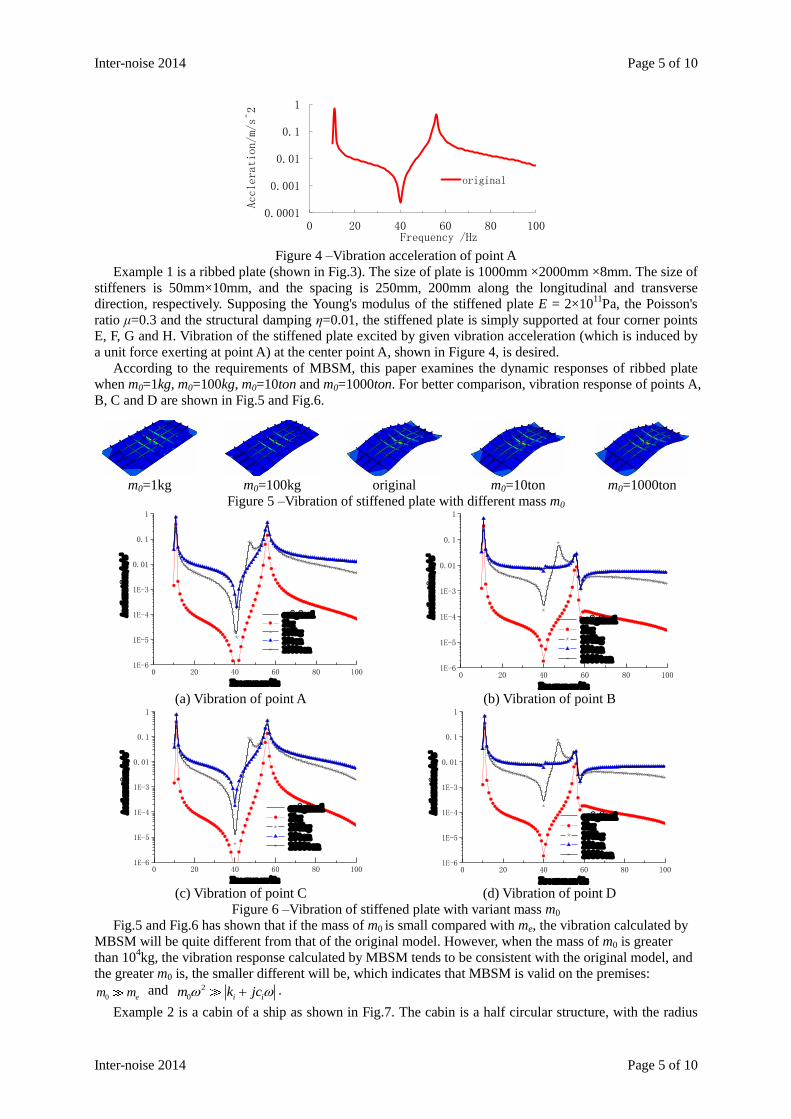
Figure 4 –Vibration acceleration of point A
Example 1 is a ribbed plate (shown in Fig.3). The size of plate is 1000mm ×2000mm ×8mm. The size of
stiffeners is 50mm×10mm, and the spacing is 250mm, 200mm along the longitudinal and transverse
direction, respectively. Supposing the Young's modulus of the stiffened plate E = 2×10¹¹
Pa, the Poisson's
ratio μ=0.3 and the structural damping η=0.01, the stiffened plate is simply supported at four corner points
E, F, G and H. Vibration of the stiffened plate excited by given vibration acceleration (which is induced by
a unit force exerting at point A) at the center point A, shown in Figure 4, is desired.
According to the requirements of MBSM, this paper examines the dynamic responses of ribbed plate
when m0=1kg, m0=100kg, m0=10ton and m0=1000ton. For better comparison, vibration response of points A,
B, C and D are shown in Fig.5 and Fig.6.
m0=1kg m0=100kg original m0=10ton m0=1000ton
Figure 5 –Vibration of stiffened plate with different mass m0
0 20 40 60 80 1001E-6
1E-5
1E-4
1E-3
0.01
0.1
1
Accleration/m/s2
Frequency/Hz
original 1kg 100kg 10ton 1000ton
0 20 40 60 80 100
1E-6
1E-5
1E-4
1E-3
0.01
0.1
1
Accleration/m/s2
Frequency/Hz
original 1kg 100kg 10ton 1000ton
(a) Vibration of point A (b) Vibration of point B
0 20 40 60 80 1001E-6
1E-5
1E-4
1E-3
0.01
0.1
1
Accleration/m/s2
Frequency/Hz
original 1kg 100kg 10ton 1000ton
0 20 40 60 80 100
1E-6
1E-5
1E-4
1E-3
0.01
0.1
1
Accleration/m/s2
Frequency/Hz
original 1kg 100kg 10ton 1000ton
(c) Vibration of point C (d) Vibration of point D
Figure 6 –Vibration of stiffened plate with variant mass m0
Fig.5 and Fig.6 has shown that if the mass of m0 is small compared with me, the vibration calculated by
MBSM will be quite different from that of the original model. However, when the mass of m0 is greater
than 104kg, the vibration response calculated by MBSM tends to be consistent with the original model, and
the greater m0 is, the smaller different will be, which indicates that MBSM is valid on the premises:
0 em m and 2
0 i im k jc .
Example 2 is a cabin of a ship as shown in Fig.7. The cabin is a half circular structure, with the radius
Page 6 of 10 Inter-noise 2014
Page 6 of 10 Inter-noise 2014
R=1500mm, 2 bulkheads at both ends. The thickness of bulkheads and circular hull is t=10mm. The size of
ribs, which is uniformly arranged in the inner side of the cabin with the spacing L of 600mm, is t=10mm,
h=200mm. Given the cabin is excited by the vibration at points A and B (shown in Figure 8), the center of
symmetry of the cabin, and supposing that the Young's modulus of ship structure E = 2×10¹¹
Pa, the
Poisson's ratio μ=0.3 and structural damping η=0.01, the underwater sound radiation of the cabin under
such vibration excitation is required when the cabin is immersed in sea water.
100 120 140 160 180 200
1.0x10⁻⁷
2.0x10⁻⁷
3.0x10⁻⁷
4.0x10⁻⁷
5.0x10⁻⁷
6.0x10⁻⁷
Accleration/m/s2
Frequency/Hz
Accleration excitation
Figure 7 –Underwater vibration and noise radiation model of a ship cabin
To facilitate analysis, according to the requirements of literature [16], infinite elements are laid out on
the outside surface of flow field the radius R=4.5m to improve the calculation accuracy. The mass of rigid
body is supposed to be m0=100kg, 1ton, 10ton and 100 ton, respectively. Responses of underwater vibration
and sound radiation of the cabin with different mass m0 are calculated and compared. Results are shown in
Fig.9 - Fig.11. Vibration gauges are in Figure7. Sound radiation gauge 5# is located at the center of
symmetry of the cabin, while the far-field sound radiation gauge 6# is right below 5# with the radius of
100m.
100 120 140 160 180 2001E-9
1E-8
1E-7
1E-6
1E-5
Accleration/m/s2
Frequency/Hz
original 100kg 1 ton 10 ton 1000 ton
100 120 140 160 180 200
1E-9
1E-8
1E-7
1E-6
1E-5
Acclerlation/m/s2
Frequency/Hz
orignial 100kg 1 ton 10 ton 1000ton
(a) vibration of point 1# (b) vibration of point 2#
100 120 140 160 180 2001E-9
1E-8
1E-7
1E-6
1E-5
Accleration/m/s2
Frequency/Hz
original 100 kg 1 ton 10 ton 1000 ton
100 120 140 160 180 200
1E-10
1E-9
1E-8
1E-7
1E-6
1E-5
Accleration/m/s2
Frequency/Hz
original 100 kg 1 ton 10 ton 1000 ton
(c) vibration of point 3# (d) vibration of point 4#
Figure 8 –Vibration of cabin with variant mass m0
Inter-noise 2014 Page 7 of 10
Inter-noise 2014 Page 7 of 10
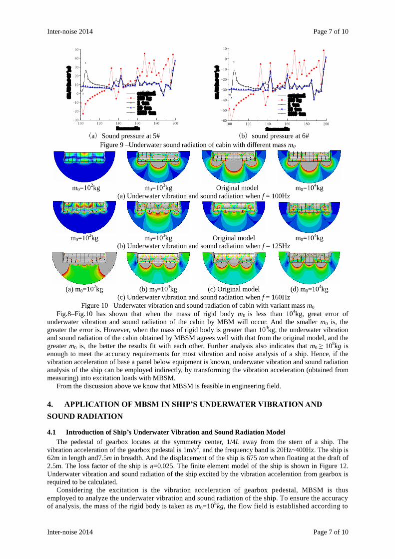
100 120 140 160 180 200-30
-20
-10
0
10
20
30
40
50
SPL/dB(Ref=10-6pa)
Frequency/Hz
original 100 kg 1 ton 10 ton 1000 ton
100 120 140 160 180 200
-60
-50
-40
-30
-20
-10
0
10
SPL/dB(Ref=10-6pa)
frequency/Hz
original 100 kg 1 ton 10 ton 1000 ton
(a)Sound pressure at 5# (b)sound pressure at 6#
Figure 9 –Underwater sound radiation of cabin with different mass m0
m0=10
2kg m0=10
3kg Original model m0=10
4kg
(a) Underwater vibration and sound radiation when f = 100Hz
m0=10
2kg m0=10
3kg Original model m0=10
4kg
(b) Underwater vibration and sound radiation when f = 125Hz
(a) m0=10
2kg (b) m0=10
3kg (c) Original model (d) m0=10
4kg
(c) Underwater vibration and sound radiation when f = 160Hz
Figure 10 –Underwater vibration and sound radiation of cabin with variant mass m0
Fig.8–Fig.10 has shown that when the mass of rigid body m0 is less than 104kg, great error of
underwater vibration and sound radiation of the cabin by MBM will occur. And the smaller m0 is, the
greater the error is. However, when the mass of rigid body is greater than 104kg, the underwater vibration
and sound radiation of the cabin obtained by MBSM agrees well with that from the original model, and the
greater m0 is, the better the results fit with each other. Further analysis also indicates that m0 ≥ 108kg is
enough to meet the accuracy requirements for most vibration and noise analysis of a ship. Hence, if the
vibration acceleration of base a panel below equipment is known, underwater vibration and sound radiation
analysis of the ship can be employed indirectly, by transforming the vibration acceleration (obtained from
measuring) into excitation loads with MBSM.
From the discussion above we know that MBSM is feasible in engineering field.
4. APPLICATION OF MBSM IN SHIP’S UNDERWATER VIBRATION AND
SOUND RADIATION
4.1 Introduction of Ship’s Underwater Vibration and Sound Radiation Model
The pedestal of gearbox locates at the symmetry center, 1/4L away from the stern of a ship. The
vibration acceleration of the gearbox pedestal is 1m/s2, and the frequency band is 20Hz~400Hz. The ship is
62m in length and7.5m in breadth. And the displacement of the ship is 675 ton when floating at the draft of
2.5m. The loss factor of the ship is η=0.025. The finite element model of the ship is shown in Figure 12.
Underwater vibration and sound radiation of the ship excited by the vibration acceleration from gearbox is
required to be calculated.
Considering the excitation is the vibration acceleration of gearbox pedestal, MBSM is thus
employed to analyze the underwater vibration and sound radiation of the ship. To ensure the accuracy
of analysis, the mass of the rigid body is taken as m0=108kg, the flow field is established according to
Page 8 of 10 Inter-noise 2014
Page 8 of 10 Inter-noise 2014
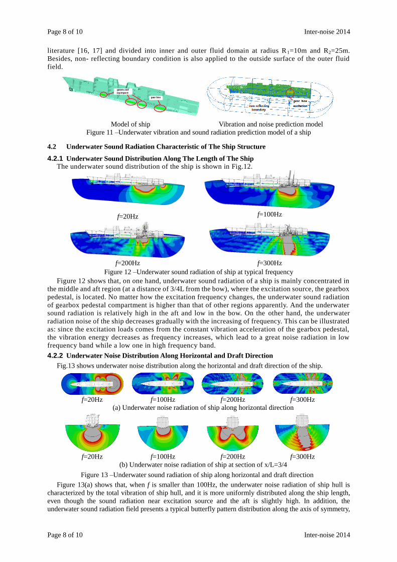
literature [16, 17] and divided into inner and outer fluid domain at radius R 1=10m and R2=25m.
Besides, non- reflecting boundary condition is also applied to the outside surface of the outer fluid
field.
Model of ship Vibration and noise prediction model
Figure 11 –Underwater vibration and sound radiation prediction model of a ship
4.2 Underwater Sound Radiation Characteristic of The Ship Structure
4.2.1 Underwater Sound Distribution Along The Length of The Ship The underwater sound distribution of the ship is shown in Fig.12.
f=20Hz f=100Hz
f=200Hz f=300Hz
Figure 12 –Underwater sound radiation of ship at typical frequency
Figure 12 shows that, on one hand, underwater sound radiation of a ship is mainly concentrated in
the middle and aft region (at a distance of 3/4L from the bow), where the excitation source, the gearbox
pedestal, is located. No matter how the excitation frequency changes, the underwater sound radiation
of gearbox pedestal compartment is higher than that of other regions apparently. And the underwater
sound radiation is relatively high in the aft and low in the bow. On the other hand, the underwater
radiation noise of the ship decreases gradually with the increasing of frequency. This can be illustrated
as: since the excitation loads comes from the constant vibration acceleration of the gearbox pedestal,
the vibration energy decreases as frequency increases, which lead to a great noise radiation in low
frequency band while a low one in high frequency band.
4.2.2 Underwater Noise Distribution Along Horizontal and Draft Direction
Fig.13 shows underwater noise distribution along the horizontal and draft direction of the ship.
f=20Hz f=100Hz f=200Hz f=300Hz
(a) Underwater noise radiation of ship along horizontal direction
f=20Hz f=100Hz f=200Hz f=300Hz
(b) Underwater noise radiation of ship at section of x/L=3/4
Figure 13 –Underwater sound radiation of ship along horizontal and draft direction
Figure 13(a) shows that, when f is smaller than 100Hz, the underwater noise radiation of ship hull is
characterized by the total vibration of ship hull, and it is more uniformly distributed along the ship length,
even though the sound radiation near excitation source and the aft is slightly high. In addition, the
underwater sound radiation field presents a typical butterfly pattern distribution along the axis of symmetry,
Inter-noise 2014 Page 9 of 10
Inter-noise 2014 Page 9 of 10
and due to the asymmetry of ship, the distribution of sound field in horizontal direction is slightly
asymmetric as well. When the exciting frequency f is greater than 200Hz, inhomogeneity distribution of
ship’s underwater sound radiation comes forth gradually. The directivity of underwater sound radiation
field becomes apparently. And moreover, the underwater sound radiation gradually follows sphere
attenuation law, which indicates the characteristics of a point source radiation. When f is greater than
300Hz, the distribution of ship’s underwater sound radiation becomes more inhomogeneous. The
propagation of underwater sound radiation turns to be more similar to the propagation ways of rays, where
sound radiation are mainly distributed around the compartment where gearbox pedestal is installed.
From Fig.13 (b) we know that, the distribution of underwater sound radiation from ship hull is
symmetric to the cross-section in general. However, due to the locally asymmetry of ship hull, underwater
sound radiation field shows some asymmetry as well. When exciting frequency is lower than 100Hz, the
underwater sound radiation field is symmetric to the cross-section and distributed at both sides of ship hull
in a butterfly-pattern. When f is greater than 200Hz, the symmetry distribution of sound field decreases, and
acoustic radiation is mainly concentrated on the area right below the gearbox pedestal. With a further
increase of exciting frequency to f is greater than 300Hz, the underwater acoustic field becomes directional
more obviously.
The foregoing analysis shows that the distribution of underwater sound radiation from ship hull is
closely related with excitation locations and frequencies. On one hand, underwater radiation noise of
the ship is mainly concentrated in the middle and aft region of the ship, where is close to the
excitations, while lower in the bow. On the other hand, in low frequency band, underwater sound
radiation from ship hull is more evenly distributed along the length of ship hull. However, with the
increase of exciting frequency, inhomogeneity distribution of the underwater sound field increases and
the directivity becomes more evident.
5. CONCLUSIONS
Based on theory of structural dynamics and taking a pedestal-equipment vibration system as an example,
this paper examines the in accordance of kinematical and mechanical boundary conditions in structural
dynamic analysis. By constructing “virtual force” to keep the consistency of moving boundaries of
structure with dynamic parameters locally unknown, MBSM is proposed to get structural dynamic response
of given moving boundary conditions with structural dynamic parameters locally unknown. On this basis,
MBSM is employed to analyze the characteristics of the underwater sound radiation of a ship. The forgoing
analysis yields:
1. MBSM proposed in this paper is feasible in structural dynamic analysis. Namely, by ensuring the
consistency of the moving boundary conditions to fabricate a virtual force, analysis for structural dynamic
response can be implemented.
2. MBSM is valid on the premises that 0 em m and 2
0 i im k jc . And the greater the mass of
rigid body m0 is, the higher the accuracy will be. If requirements of MBSM are not satisfied with,
significant errors will occur.
3. Ship’s underwater sound radiation is closely related with factors such as excitation locations and
frequencies. On one hand, ship’s underwater noise radiation is mainly concentrated in the middle and
aft region of ship hull which is close to the excitation source, and becomes lower in the bow. On the
other hand, in low frequency band, ship’s underwater sound radiation is more evenly distributed along
the ship length, while more inhomogeneous and directive with the increasing of exciting frequency.
ACKNOWLEDGEMENTS
This research was supported by National Natural Science Foundation China (No.51209052),
Heilongjiang Province Natural Science Foundation (QC2011C013), Harbin Science and Technology
Development Innovation Foundation of youth (2011RFQXG021),Fundamental Research Funds for the
Central Universities (HEUCF40117), High Technology Ship Funds of Ministry of Industry and
Information Technology of P.R.China, Opening Funds of State Key Laboratory of ocean Engineering
of Shanghai Jiaotong University (No.1307) and post-doctoral funds. Their support and assistance are
gratefully acknowledged.
REFERENCES
1. Weilin Tang, Rongbing He. Approximate analytical solution of vibration and sound radiation from


![Computationally efficient boundary element methods for high … · 2016. 4. 13. · 1 Introduction The boundary element method (BEM) ... [1, 2]. This will be the topic of Section](https://static.documents.pub/doc/80x56/60e17e1cffcab14e2972cda3/computationally-eficient-boundary-element-methods-for-high-2016-4-13-1-introduction.jpg)


![A HYBRID BOUNDARY ELEMENT METHOD FOR ELLIPTIC … · Laplace equation. The method of choice is the boundary element method (BEM) [4, 5] that is already a very commonly used technique](https://static.documents.pub/doc/80x56/5e7a2978f9b7b86a634c67c9/a-hybrid-boundary-element-method-for-elliptic-laplace-equation-the-method-of-choice.jpg)


