35
MOWER/SHREDDERS Operation, Service, & Parts Manual For Models SFG95, 125, 140, 155, 185, & 200 October 2009 Form: SFGShredder.indd

MOWER/SHREDDERS
Operation, Service,& Parts Manual ForModels SFG95, 125, 140, 155, 185, & 200
October 2009
Form: SFGShredder.indd

PAGEGeneral Information ......................................................................................... 1 Introduction ........................................................................................... 1 Symbols .................................................................................................. 1
Terminology ........................................................................................................ 2 Main Parts Terminology ...................................................................... 2 Identifi cation Plate ................................................................................ 2 Safety Labels ....................................................................................................... 3
Safety ................................................................................................................. 4 Allowed Use ........................................................................................... 4 Improper Use ........................................................................................ 4 Safety in the Workplace ........................................................................ 4 Operator's Requirements ............................................................... 4 - 5 Work Clothing ....................................................................................... 5 General Safety Rules ....................................................................... 5 - 7 Transport Safety .................................................................................... 7
Set-Up ................................................................................................................. 8 Attachment to the Tractor ............................................................. 8 - 9 Driveline Attachment ........................................................................... 9 Hydraulics Connections ....................................................................... 9 Machine Use ........................................................................................10 Working Speed ....................................................................................10 Machine Disconnection .....................................................................10 Storage ..................................................................................................11
Adjustments ......................................................................................................12 Working Height Adjustment .............................................................12 Rear Wheel Adjustment .....................................................................13 Rear Roller Adjustment ......................................................................13 Side Shift Adjustment ........................................................................14 Rear Hatch Adjustment .....................................................................15 Belt Tension Adjustment ...................................................................15 Wood Shredding ..................................................................................16 Feeler Arm & Spring Loader Arm ...........................................16 - 17 Blades/Hammers ................................................................................17
TABLE OF CONTENTS

TABLE OF CONTENTS
PAGEMaintenance ..............................................................................................18 - 22 Maintenance of Machine ...........................................................18 - 19 Torque Specifi cations .........................................................................19 Feeler and Spring Loaded Arms .......................................................21 Y Blades/Hammers ............................................................................22 Belt Replacement ................................................................................22 Hose Replacement ..............................................................................22
Troubleshooting ...............................................................................................23 Spare Parts Ordering ..........................................................................23
Transport & Storage ........................................................................................24 Working Speed ....................................................................................24 Road Transport ...................................................................................24 Storage ..................................................................................................24
Parts .......................................................................................................25 - 31 Flail Mower Parts ........................................................................25 - 30 Driveline ...............................................................................................31
Limited Warranty .............................................................................................32

GENERAL INFORMATION
1
INTRODUCTION:
The SFG Flails are primarily designed to mow grass, weeds and light brush.
The mowers are assembled for operation with 540 RPM tractor input only (rated PTO up to 70 HP), and supplied standard with Cat. I lift pins for tractor attachment.
The mowers can fi t Cat. I quick attach hitch, by using suitable bushings to adapt diameters of lift pins.
SYMBOLS:
This booklet contains three "safety graphic symbols" which highlight the relevant danger levels or important information:
____________________________________________________________________________________________
It draws the operator's attention to situations which can jeopardize people's safety._____________________________________________________________________________
_____________________________________________________________________________
It draws the attention to situations which jeopardize the machine effi ciency but not people's safety._____________________________________________________________________________
_____________________________________________________________________________
It highlights general information which does not endanger people's safety or the effi ciency of the parts._____________________________________________________________________________
MAIN PARTS TERMINOLOGY
2
MAIN PARTS TERMINOLOGY:
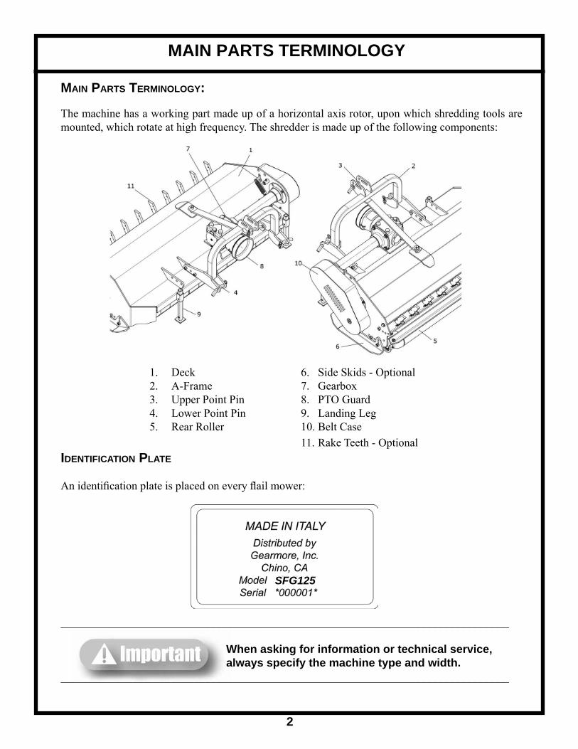
The machine has a working part made up of a horizontal axis rotor, upon which shredding tools are mounted, which rotate at high frequency. The shredder is made up of the following components:
1. Deck 6. Side Skids - Optional 2. A-Frame 7. Gearbox 3. Upper Point Pin 8. PTO Guard 4. Lower Point Pin 9. Landing Leg 5. Rear Roller 10. Belt Case 11. Rake Teeth - OptionalIDENTIFICATION PLATE
An identifi cation plate is placed on every fl ail mower:
_______________________________________________________________________________
When asking for information or technical service, always specify the machine type and width._______________________________________________________________________________
SFG125
SAFETY LABELS
3
SAFETY LABELS:
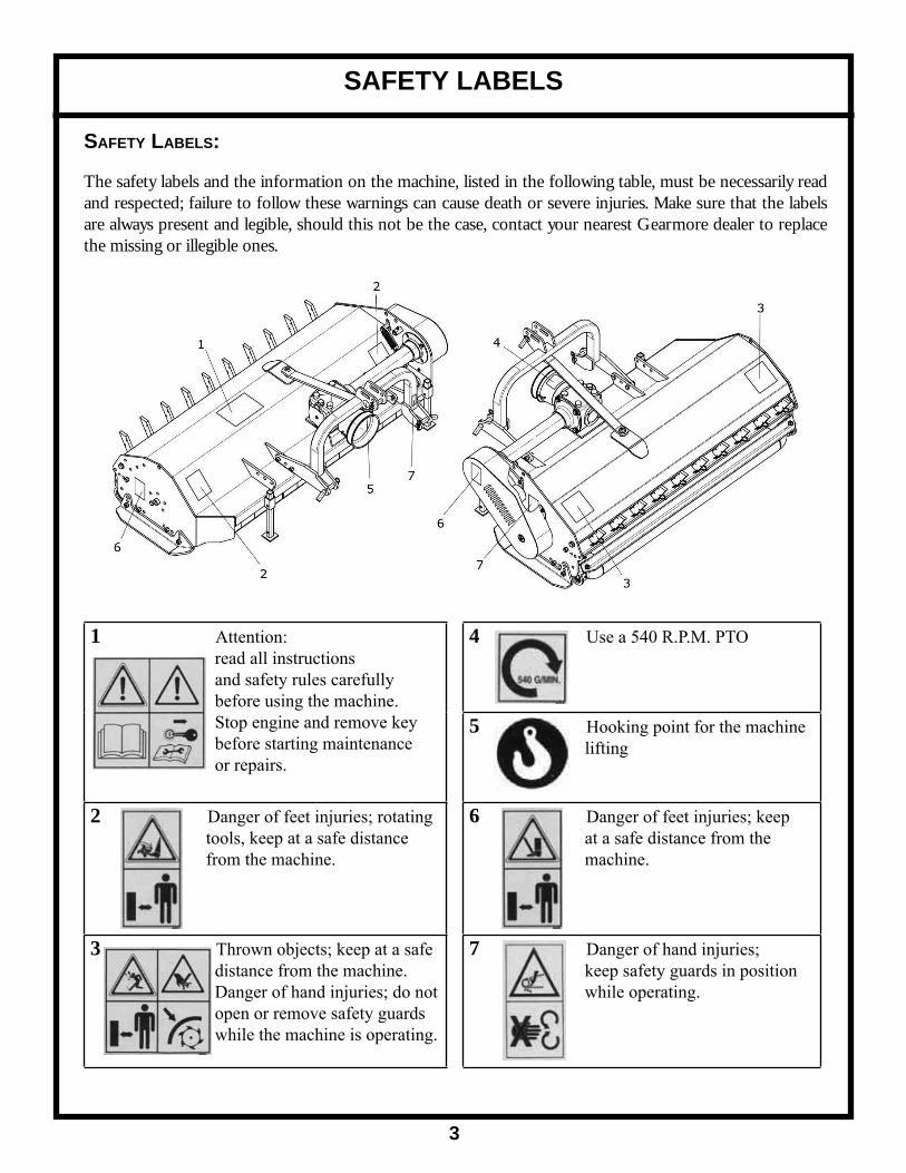
The safety labels and the information on the machine, listed in the following table, must be necessarily read and respected; failure to follow these warnings can cause death or severe injuries. Make sure that the labels are always present and legible, should this not be the case, contact your nearest Gearmore dealer to replace the missing or illegible ones.
1 Attention: read all instructions and safety rules carefully before using the machine. Stop engine and remove key before starting maintenance or repairs.
4 Use a 540 R.P.M. PTO
5 Hooking point for the machine lifting
2 Danger of feet injuries; rotating tools, keep at a safe distance from the machine.
6 Danger of feet injuries; keep at a safe distance from the machine.
3 Thrown objects; keep at a safe distance from the machine. Danger of hand injuries; do not open or remove safety guards while the machine is operating.
7 Danger of hand injuries; keep safety guards in position while operating.

SAFETY
4
ALLOWED USE:
SFG fl ail mowers, as described in this instruction and maintenance booklet, have been specifi cally designed to mow grass, weeds, and light brush up to 2" diameter. Any other use jeopardizes the operator's safety and the machine integrity.
IMPROPER USE:
The mower was designed to mow grass, weeds, and light brush only. Only operate this mower on a properly sized and equipped tractor.
When using SFG fl ail mowers, it is particularly forbidden:
- The attachment to vehicles of unsuitable power or weight. - To use other than 540 R.P.M. PTO speed. - To use the machine without inserting the pins and cotter pins when supplied. - To work in excessively stony grounds. - To work on excessive slopes. - To lift the machine when the power take off is engaged. - To approach the machine when wearing inappropriate work clothing. - To get on the machine while it is being used or transported.___________________________________________________________________________________
Operating this mower in an application for which it is not designed and/or operating with the wrong size tractor can cause mower component damage and equipment failure resulting in possible serious injury or death.___________________________________________________________________________________
SAFETY
SAFETY IN THE WORKPLACE:
Most of the accidents which take place while the operator is using the machine or the equipment or during their maintenance or repair are caused by a lack of compliance with the basic safety precautions. It is necessary, therefore, to become more and more conscious of the potential risks of one's action by constantly paying attention to its effects.
If potentially dangerous situations are known, accidents can be prevented!
OPERATOR'S REQUIREMENTS:
All operators using the equipment must be competent and meet necessarily the following features:
Physical: good eyesight, coordination and capability of carrying out all functions required for the machine's use.

Mental: Capability of understanding and applying the established rules and safety precautions. Users must pay attention and be sensible for their own and other people's safety.
Training: users must have read and studied this manual, its eventual enclosed graphs and schemes and its identifi cation and danger plates. They must be skilled and trained on any use or maintenance activities.
WORK CLOTHING:
When working and especially when executing repair or maintenance activities, it is necessary to wear the following clothing and safety accessories:
- Overalls or other comfortable clothing, not too loose to prevent the possibility that parts of them might be caught in the moving parts.
- Protective gloves for hands.
- Protective glasses or faceplate to protect eyes and face.
- Protective helmet for the head.
- Safety shoes______________________________________________________________________________________
Wear only personal safety accessories in good condition and complying with the rules in force.______________________________________________________________________________________GENERAL SAFETY RULES
ALWAYS CONSIDER THE FEATURES OF THE AREA WHERE WORK IS TAKING PLACE:
- When the equipment is running, it is forbidden to stand within the fi eld of action of the shredder or of the other accessories of which it is provided with.
PREPARE THE WORK:
- Before and when working, do not drink alcohol, take drugs, or any other substances which may alter your capability of working with machine tools.
- Be sure to have suffi cient fuel, to prevent a forced stopping of the machine, maybe during a critical movement.
- Do not use the equipment under unsafe conditions. For instance, it is forbidden to execute makeshift repair activities just to start working; it is forbidden to work at night with an insuffi ciently illuminated working area.
SAFETY
5
SAFETY
6
- NEVER operate implement without all shields in place and in good operational condition. The operator must be familiar with the mower and tractor and all associated safety practices before operating the mower and tractor.
WHEN WORKING OR DURING THE MAINTENANCE ACTIVITIES IT IS NECESSARY TO REMEMBER:
- The labels and stickers providing instructions and pointing out the dangers, must not be removed, hidden, or made illegible.
- Do not remove, except in case of maintenance, the shields, guards, and defl ectors equipped on the mower. When it is necessary to remove them, stop engine, handle with care and reassemble them properly before restarting the engine and using the equipment. The mower is equipped with protective defl ectors to prevent objects being thrown from the mower by the blades, however, no shielding is 100% effective. All shields, guards, and defl ectors equipped on the mower must be maintained in good operational condition.
- It is forbidden to lubricate, clean and adjust the moving parts while they are running.
- During maintenance or adjustment activities on the equipment it is forbidden to use hands for executing operations for which there are specifi c tools.
- Do not use tools in bad condition or inappropriately, for instance pliers rather than monkey spanners, etc.
- When maintenance or repairs are completed check out that no tools, wiping rags, or other materials are left inside spaces or guides with moving parts.
- While using the equipment, it is forbidden to make more than one person give directions and make signals. The eventual directions and signals relating to the load handling must be given by one person only.
- Do not unexpectedly call an operator while he is working if not necessary; it is forbidden as well to frighten or throw objects at the operator, even if just for fun.
- Watch out for those who are present, especially the children!
- Do not make people get on the machine.
- When the equipment is not needed, stop the vehicle's engine, park it on fl at ground with fi rst speed and parking brake on, with the machine rested on the ground and PTO disengaged.
- Do not clean, lubricate, repair or adjust with the engine running and the machine lifted.
- Never use the machine on steep slopes which may jeopardize the equipment's stability.
The manufacturer declines all responsibility for a lack of compliance with these instructions.
SAFETY
7
- NEVER use gasoline, solvents, or other fl ammable or toxic liquids to clean mechanical parts. Use approved non-fl ammable, non-toxic commercial solvents.
- DO NOT weld near tanks, piping, cans, electrical cables or fl ammable materials in general. When welding, protect fl ammable parts with appropriate shields.
Gearmore declines all responsibility for a lack of compliance with these standards.
ROAD TRANSPORT
While transporting the machine it is very important to follow the road traffi c code of the country where you circulate, placing particular attention on the choice of speed.
When transporting on a public road, the shredder must be in the transport position and the power take-off of the tractor must be disconnected. Machine weight changes the stability of the tractor/shredder complex, infl uencing steering and braking capability. Therefore proceed at a moderate speed.
Check the lifting capability and tractor stability. If needed apply ballasts on the front.
MOVEMENT AND TRANSPORTATION
Pay maximum attention to safety during loading and unloading operations, which must be carried out by qualifi ed personnel.
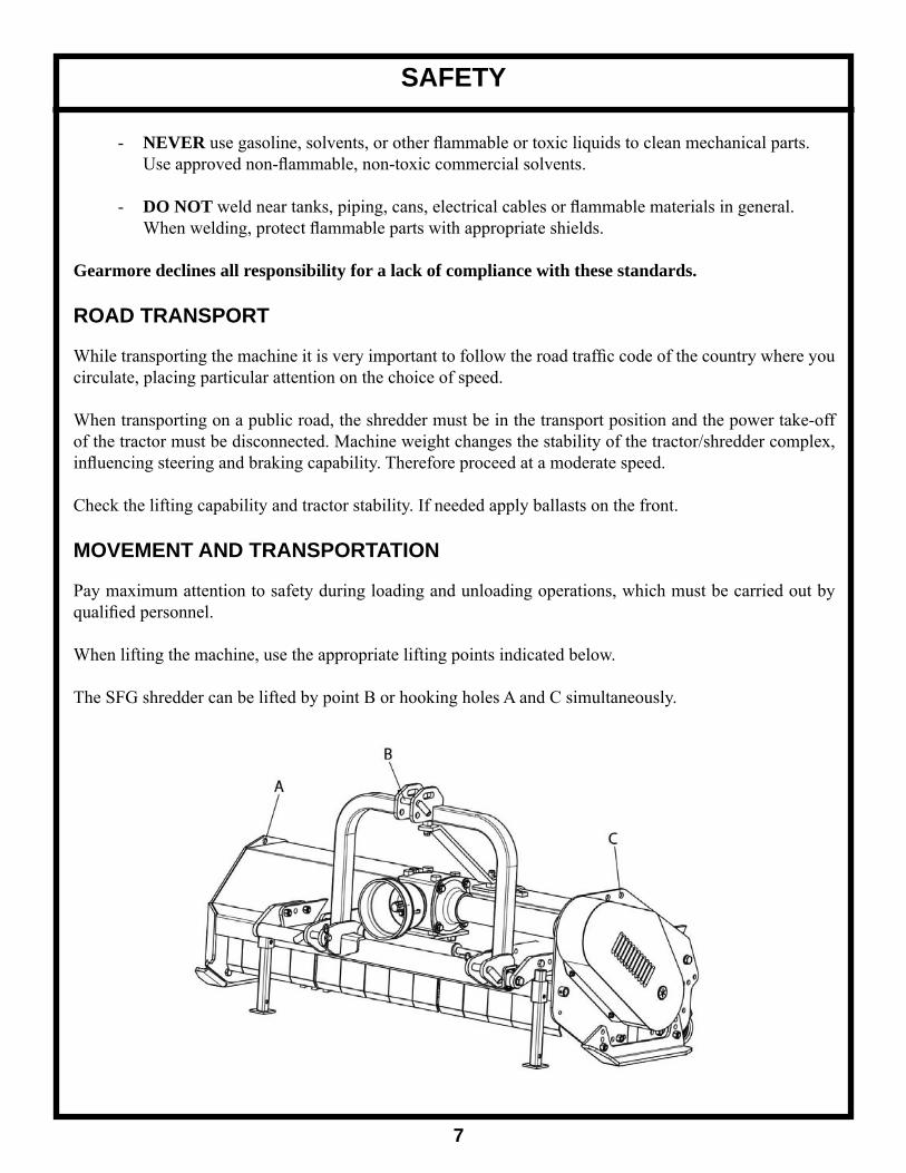
When lifting the machine, use the appropriate lifting points indicated below.
The SFG shredder can be lifted by point B or hooking holes A and C simultaneously.

SET-UP
8
Before using the machine, one must be familiar with the controls and their work capabilities. Always keep all body parts inside of the tractor cabin, to reduce the possibility of being exposed to external dangers to a minimum.
Before exiting the tractor and before any maintenance and adjustment operation, set the parking brake, turn off the engine, remove the ignition key and wait for all moving parts to stop.
The safety of the operator and of the persons nearby depends on his ability for judgment and prudence in using the machine. Therefore the position and functions of all controls must be known well.
The machine must always be in perfect conditions and must be repaired only with original spare parts. CONNECTING THE MACHINE TO THE TRACTOR
It is necessary to read this instruction manual and the manuals of the tractor and driveline manufacturers. Shredders have been manufactured to be attached to any tractor provided with a hydraulic lift and a universal 3-point hitch. The machine must be connected to the tractor with a 540 R.P.M. PTO having adequate weight and power. Before attaching the equipment to the tractor, set both on a fl at and smooth ground and make sure that nobody is standing between them. Move the tractor slowly towards the shredder by aligning the tractor lift's arms to the two shredder lower a-frame brackets. Stop the engine and set the parking brake.
First connect the lower arms by removing the release pins of the brackets placed on the plates, inserting the lift bars into the arms center and fastening them with the relevant pins, which had been removed.
Connect the tractor top link to the third upper point by removing the pin located between the plates, inserting the top link itself and locking it with the pin. Adjust the third point so that the upper part of the frame is parallel to the ground. Lock all connection parts with the special sway chains or tie rods.
It is always good to make sure that the central group axis is parallel to the ground thus reducing the stress on the PTO and extending the working life of the equipment.

SET-UP
9
_____________________________________________________________________________________
Pay attention to the tractor's front wheels grip when the equipment is set up and lifted; if the wheels appear to be too lightened, ballast the tractor front tires or add front weights._____________________________________________________________________________________________________________________________________________________________________________
After executing the above-mentioned activities it is always good to check that all bolts and nuts of your shredder are tightened (refer to the torque specifi cations in this manual)._____________________________________________________________________________
DRIVELINE ATTACHMENT
Before assembling the PTO shaft, it is very important to check out that its number of revolutions and direction of rotation match those of the tractor. Moreover, read the manufacturer instruction manuals of the driveline and the tractor carefully. Before starting work, check the presence of the safety guards on the PTO of the machine, of the shaft and of the tractor. Check in particular that the safety guards cover the driveline throughout its extension._____________________________________________________________________________________
When at their maximum extension, the safety guards' plastic hoses shall overlap at least 1/3 of their length. When in their maximum closed position, the minimum play allowed shall be ¾ "._____________________________________________________________________________
Check out that the driveline minimum and maximum length are the ones required by the machine/tractor coupling. Should problems arise, contact a skilled repair shop or the driveline retailer. After installation, secure safety guards both to the tractor and the machine using the special chains and make sure that they pivot freely. Do not use a shaft without proper safety guards complying with legal requisites. If the shaft is equipped with other safety devices, such as a pair limiter or freewheels, be sure to install them on the machine side. As for the driveline use and maintenance, refer to the relevant booklet.
_____________________________________________________________________________________
Avoid going near the driveline, either in movement or stopped._____________________________________________________________________________
HYDRAULIC CONNECTIONSIf your machine is provided with hydraulic movement, connect the ends of the delivery and return cylinder tubes, provided with quick coupling, to the tractor hydraulics utilities. Check the sealing of the connections and become familiar with the movements controls.
SET-UP
10
MACHINE USE
Before using the machine for the fi rst time, or after a long period of inactivity, carry out the following: √ Check that the machine is not damaged √ Check the mechanical parts, which must be in good condition and not rusted √ Check the state of wear of the blades √ Check that there is not oil leakage coming from fi ttings or piping √ Check that all safety guards are properly positioned
When these check-ups have been carried out, do not start the PTO with the shredder at work height but only after having lifted it up a few centimeters with the tractor lift. After this, it is possible to start engine, engage PTO, drop the machine down to work position and start using it. In the same way for operations involving change of direction, turning and going in reverse, lift the head a bit from the ground, after having disengaged the PTO, in order to avoid structure damage.
Before using the machine, one must be familiar with the controls and their work capabilities. Before starting work, make sure that no people or animals are within 100 feet. Keep the engine running at a rev speed that assures the machine the needed power for its use. Run a short way with the shredder working and check the quality of the work carried out. If it does not satisfy you, repeat and review the machine adjustment operations.
WORKING SPEED
The tractor speed during work depends on the quality, diameter and height of the material to be cut. However it should be between 2 and 6 MPH. The PTO speed must be within 540 R.P.M.
MACHINE DISCONNECTION
When the machine is parked, one must:
~ Set the parking brake ~ Lower the machine resting feet ~ Place the shredder on the ground ~ Disengage the tractor PTO ~ Turn the tractor engine off ~ Remove the ignition key from the control panel ~ Descend from the driver position ~ Detach the driveline ~ Remove a-frame pins ~ Get back onto the tractor, start it up and move away carefully
SET-UP
11
STORAGE
If the machine is not to be used for long periods, it must be stored in a place sheltered from atmospheric conditions and be protected to avoid damage. Before setting it aside, clean the whole machine and lubricate all mechanical parts to protect them from rust.
Before setting the machine aside for long periods, perform the following:
● Free the rotor and the blades from shredding remains ● Wash the machine thoroughly and dry it ● Carry out a general visual control of the machine to identify structural damage, to detect deep paint abrasions, to check that all original safety decals are in place, and that they are integral and legible ● Grease all mechanical parts and fastening pins ● If possible, store the machine in a covered place, on fl at and consistent ground
___________________________________________________________________________________
Used oil must be recovered and not dispersed in the environment, according to the legal standards in force. Used oil is classifi ed as dangerous waste and as such must be brought to the appropriate collection center.____________________________________________________________________________

WORKING HEIGHT ADJUSTMENT
The machine working height is determined by the vertical position of the rear roller, by that of the skids and/or, where required, by the rear wheels.
Lifting the roller, or the wheels, the tools near the ground and, vice versa, lowering the roller, and the wheels, the tools lift up form the ground. After a modifi cation of the working height be sure that the cutters skim the ground; a direct contact with it would cause their wear.
To adjust the skid position (fi g. 1) carry out the following operations (optional):
● Unscrew nuts A ● Slip the skid off ● Reinsert it in one of the holes B ● Tighten the nuts A (refer to the torque specifi cation chart in this booklet)
Do the same thing on the opposite side of the machine.
The roller can be adjusted both horizontally and vertically.To adjust the roller height (fi g. 2): ● Unscrew and remove the bolts B which fasten the roller on both sides ● Loosen the nut A ● Raise or lower the roller and reposition it according to the layout ● Reinsert and tighten the bolts B ● Tighten the nut A
There are 3 height positions of the rear roller for blade ground clearance 1/2", 1", or 2 1/2".____________________________________________________________________________________
These operations shall be made only on working ground and only after having stopped the engine, disengaged the PTO and set the parking brake. If necessary, lift the machine from the ground but, in order to avoid risks for people, place it on rests thus preventing any injuries that might be caused by its sudden fall.____________________________________________________________________________
ADJUSTMENTS
12
Fig. 1
Fig. 2

Rear Roller Adjustment:The roller's horizontal position must be adjusted to modify the work confi guration of the shredder.
To move the roller horizontally (fi g. 2):
● Unscrew and remove the bolts B and screws A which fasten the roller on both sides ● Place the roller at the desired position according to the layout in ( fi g. 4) ● Reinsert and tighten the bolts A and B (refer to the torque specifi cation chart)
REAR WHEEL ADJUSTMENT - OPTIONAL
SFG options include rear wheels. To adjust the wheel height (fi g. 3): ● Loosen the screws A on both sides ● Unscrew and remove the screws B on both sides ● Lift or lower wheels C through the holes D equally on the left and right sides ● Reinsert and tighten the screws B ● Tighten the screws A
ADJUSTMENTS
13
Fig. 3
Fig. 4
SIDE SHIFT ADJUSTMENT
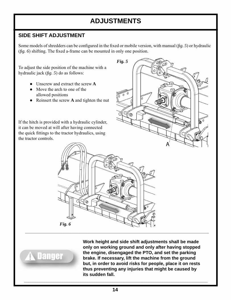
Some models of shredders can be confi gured in the fi xed or mobile version, with manual (fi g. 5) or hydraulic (fi g. 6) shifting. The fi xed a-frame can be mounted in only one position.
To adjust the side position of the machine with a hydraulic jack (fi g. 5) do as follows:
● Unscrew and extract the screw A ● Move the arch to one of the allowed positions ● Reinsert the screw A and tighten the nut
If the hitch is provided with a hydraulic cylinder, it can be moved at will after having connected the quick fi ttings to the tractor hydraulics, using the tractor controls.
ADJUSTMENTS
14
_________________________________________________________________________________
Work height and side shift adjustments shall be made only on working ground and only after having stopped the engine, disengaged the PTO, and set the parking brake. If necessary, lift the machine from the ground but, in order to avoid risks for people, place it on rests thus preventing any injuries that might be caused by its sudden fall._________________________________________________________________________________
Fig. 5
Fig. 6

REAR HATCH ADJUSTMENT
The shredder is provided with swinging rear hatch, which can be oriented depending on the type of material to be shred.
To work in the presence of pruning remains, the baffl e must be closed to obtain a better shredding. To do this, the hatch must be in the down position, to allow the rakes to be inserted (fi g. 7).
To shred grass fi elds, the hatch must be open (after having removed the rakes) and the roller must be moved to the forward position to allow a better outlet for cut grass to avoid obstructions (fi g. 8).
To adjust the hatch (fi g. 9):
● Loosen the screws A which fasten the cover on both sides ● Unscrew and remove the bolts B ● Rotate the cover based on the holes C on the side plate of the frame until reaching the desired opening ● Tighten the screws A (according the torque specifi cation chart)
BELT TENSION ADJUSTMENT
The blade rotor is made to rotate by means of belt transmission with an automatic spring tensioner.
To adjust the belt transmission tension, proceed as follows (fi g. 10):
● Loosen the counter nut A ● Tighten the nut B to tension the spring ● When the adjustment is carried out, tighten the counter nut A
The belts are properly tensioned when, applying a force of about 40 lbs. on the tensioned side of the belt set, they should defl ect about 3/4 of an inch.
ADJUSTMENTS
15
Fig. 7
Fig. 8
Fig. 9
Fig. 10
ADJUSTMENTS
16
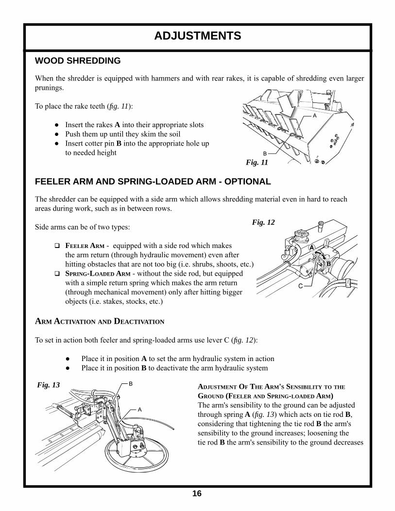
WOOD SHREDDING
When the shredder is equipped with hammers and with rear rakes, it is capable of shredding even larger prunings.
To place the rake teeth (fi g. 11):
● Insert the rakes A into their appropriate slots ● Push them up until they skim the soil ● Insert cotter pin B into the appropriate hole up to needed height
FEELER ARM AND SPRING-LOADED ARM - OPTIONAL
The shredder can be equipped with a side arm which allows shredding material even in hard to reach areas during work, such as in between rows.
Side arms can be of two types:
FEELER ARM - equipped with a side rod which makes the arm return (through hydraulic movement) even after hitting obstacles that are not too big (i.e. shrubs, shoots, etc.) SPRING-LOADED ARM - without the side rod, but equipped with a simple return spring which makes the arm return (through mechanical movement) only after hitting bigger objects (i.e. stakes, stocks, etc.)
ARM ACTIVATION AND DEACTIVATION
To set in action both feeler and spring-loaded arms use lever C (fi g. 12):
● Place it in position A to set the arm hydraulic system in action ● Place it in position B to deactivate the arm hydraulic system
ADJUSTMENT OF THE ARM'S SENSIBILITY TO THE GROUND (FEELER AND SPRING-LOADED ARM) The arm's sensibility to the ground can be adjusted through spring A (fi g. 13) which acts on tie rod B, considering that tightening the tie rod B the arm's sensibility to the ground increases; loosening the tie rod B the arm's sensibility to the ground decreases
Fig. 11
Fig. 12
Fig. 13

ADJUSTMENTS
17
ADJUSTMENT OF THE FEELER ARM WORKING AMPLITUDE
To adjust the working amplitude radius of the feeler arm (fi g. 14):
● Extract the support B ● Adjust the length of the screw A considering that the shorter the screw is the greater the rod's radius amplitude (thus increasing the working amplitude) ● After adjustment, reinsert the support B
ADJUSTMENT OF SPRING LOADED ARM RESISTANCE TO OBSTACLES
To adjust the spring loaded arm's resistance to obstacles, use the return spring A (fi g. 15) moving it to the right on the hooking support B to decrease the arm resistance to obstacles, and vice versa to the left to increase resistance to obstacles.
BLADES/HAMMERS
The SFG shredders can be equipped with different types of double Y blades or hammers according to the work to be done. Y Blades and hammers are interchangeable on the same rotor shaft.
ALL PURPOSE DOUBLE Y BLADES - for grass, straw and weeds.
SMOOTH HAMMER - for grass, pruning remains and small shrubs.
Fig. 14
Fig. 15
_________________________________________________________________________________
These operations shall be made only on working ground and only after having stopped the engine, disengages the PTO, and set the parking brake. If necessary, lift the machine from the ground but, in order to avoid risks for people, place it on rests thus preventing any injuries that might be caused by its sudden fall._________________________________________________________________________________

MAINTENANCE
18
Maintenance is a fundamental operation to extend life and performances of any agricultural vehicle; taking care of the machine grants you not only a good work execution, but also a longer life of the whole equipment and a greater safety in the workplace.
The operating times indicated in this manual have just an informative character and are referred to normal conditions of use. They can thus undergo variations according to the type of service, to the more or less dusty environment, to seasonal factors, etc.
Before starting any maintenance, the following operations must be carried out:
- The machine must be placed on fl at compact ground during maintenance - Turn the tractor engine off, set the parking brake and remove the ignition key - Always use appropriate individual safety devices (accident prevention shoes, work overalls and gloves, anti-dust mask, etc.) - Prepare all that is prescribed for accident prevention for the type of operation in progress - If compressed air is used to clean the machine, appropriate glasses are needed - Do not carry out unknown repairs. Always follow the instructions. If they are missing, contact the supplier or expert personnel - Do not use lifting points different from those prescribed - Make sure that the chosen lifting device is suitable to carry out operations in compliance with safety standards - Do not leave the tractor engine running in closed places if they do not have a ventilation system suitable to remove toxic gas exhaust concentrated in the air - Avoid prolonged and repeated skin contact with lubricants as they could harm skin and cause other problems - In case of accidental contact with eyes, wash them well with water - Pay maximum attention to possible elevated temperatures in drained oil - Do not weld in closed spaces or in those which are not properly ventilated - Do not weld on or near painted surfaces, to avoid the forming of toxic vapors. Remove paint with suitable products and then wash the surfaces and let them dry - Discharge pressure from circuits before carrying out interventions - Do not identify pressurized liquid leakage by hand - Pressurized liquid leakage can penetrate the skin and eyes with very grave consequences _________________________________________________________________________________
Before injecting lubricating grease into the zerks, clean them thoroughly to prevent mud, dust or other foreign matters from mixing up with grease, thus diminishing the lubrication effect.
When adding or changing oil, it is better to use the same oil type in order to avoid mixing oils with different features.
After the fi rst working hour, check that all bolts and nuts are tightened; remember also to check all the machine safety guards often._________________________________________________________________________________

MAINTENANCE
19
TORQUE SPECIFICATIONS
For correct hardware tightening on the mower, we suggest the use of a suitable torque wrench and the applicable torque as listed in the table.
M-THREADED SCREW / BOLTSBolt Grade
Thread 8.8 10.9Nm lb / ft Nm lb / ft
M6 11 8.5 17 12M8 28 20 40 30M10 55 40 80 60M12 95 70 140 105M14 150 110 225 165M16 240 175 305 225M18 330 250 475 350
LUBRICATION ● Grease points - use high quality lithium based grease ● Gearbox - use 90 weight oil
MAINTENANCE SCHEDULE
FIRST CHECK: ● Check the correct tension of the transmission belt ● Check that all bolts and nuts are tightened ● After the fi rst 50 hours of work change oil n the overgear unit
EVERY 8 HOURS OF WORK: ● Grease the shaft support (transmission side) through the lubricating zerk A (fi g. 16) ● Grease the shaft support (external side) through the lubricating zerk A (fi g. 17) ● Grease the stabilizing roller through the lubricating zerk A (fi g. 18) ● Grease the side shift rods through the lubricating zerk A (fi g. 19)
EVERY 50 HOURS OF WORK: ● Check the correct tension of the transmission belt ● Check that all bolts and nuts are tightened ● Check the cutters/hammers for wear ● Check the gearbox oil level through plug A (fi g. 20)
EVERY 500 HOURS OF WORK: ● Check that all bolts and nuts are tightened ● Change oil in the gearbox
EVERY 1000 HOURS OF WORK: ● Replace the transmission belt

MAINTENANCE
20
Fig. 16 Fig. 17
Fig. 18 Fig. 19
Fig. 20
MAINTENANCE
21
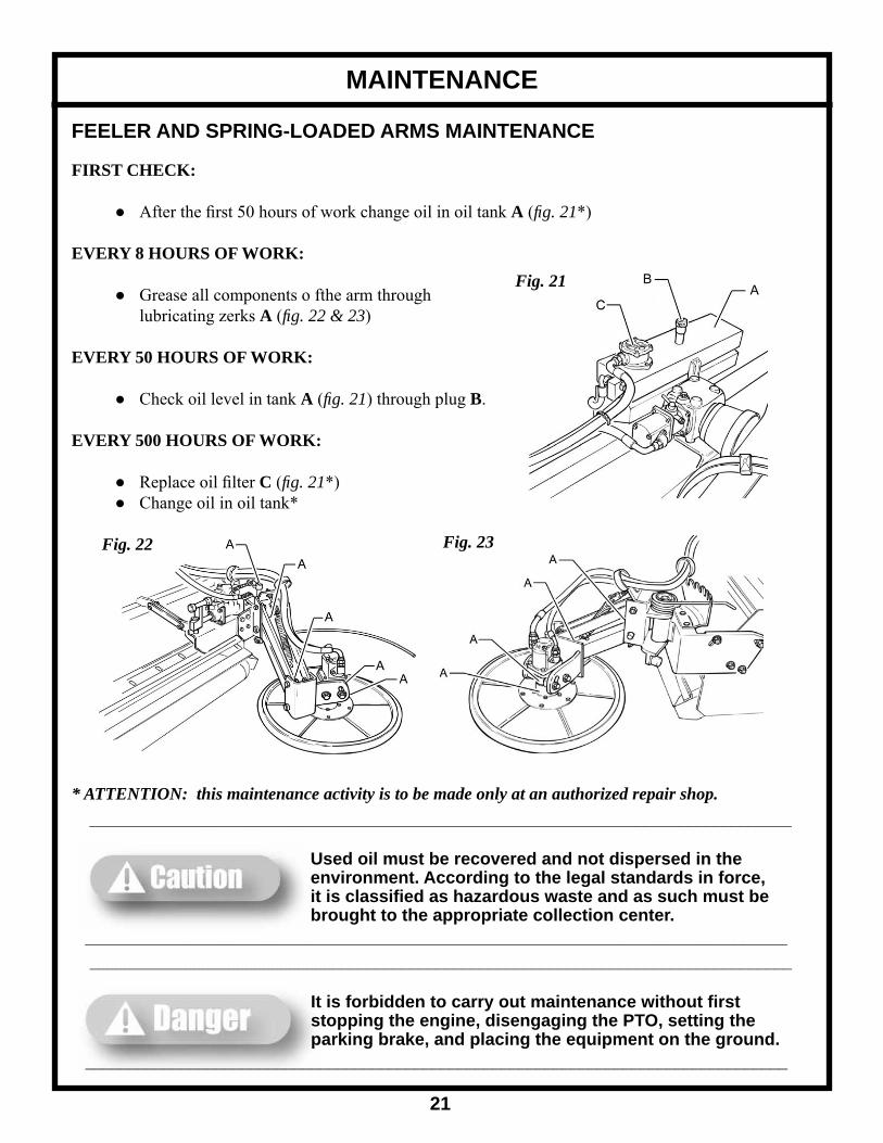
FEELER AND SPRING-LOADED ARMS MAINTENANCE
FIRST CHECK:
● After the fi rst 50 hours of work change oil in oil tank A (fi g. 21*)
EVERY 8 HOURS OF WORK:
● Grease all components o fthe arm through lubricating zerks A (fi g. 22 & 23)
EVERY 50 HOURS OF WORK:
● Check oil level in tank A (fi g. 21) through plug B.
EVERY 500 HOURS OF WORK:
● Replace oil fi lter C (fi g. 21*) ● Change oil in oil tank*
* ATTENTION: this maintenance activity is to be made only at an authorized repair shop.
Fig. 22 Fig. 23
Fig. 21
_________________________________________________________________________________
Used oil must be recovered and not dispersed in the environment. According to the legal standards in force, it is classifi ed as hazardous waste and as such must be brought to the appropriate collection center. _________________________________________________________________________________ _________________________________________________________________________________
It is forbidden to carry out maintenance without fi rst stopping the engine, disengaging the PTO, setting the parking brake, and placing the equipment on the ground._________________________________________________________________________________
Y BLADES OR HAMMERS
To assure a perfect functioning of the machine, check often (at least every 50 hours of work) that the shredder's hammers are in good condition and perfectly fi xed by the locking bolts; in case they are broken replace them with new original spare parts.
For any blade or hammer replacements, please contact your authorized Gearmore dealer.
When one blade is replaced, it is advisable to replace the whole series. Use of unoriginal blades can cause vibrations of the machine.
When replacing blades with the machine lifted, do not trust the capacity of the tractor's hydraulic lift. Insert mechanical posts or support tripods between the machine and the ground in order to avoid unwanted and dangerous situations.
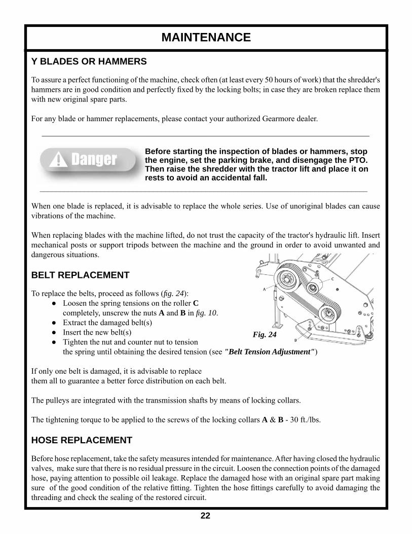
BELT REPLACEMENT
To replace the belts, proceed as follows (fi g. 24): ● Loosen the spring tensions on the roller C completely, unscrew the nuts A and B in fi g. 10. ● Extract the damaged belt(s) ● Insert the new belt(s) ● Tighten the nut and counter nut to tension the spring until obtaining the desired tension (see "Belt Tension Adjustment")
If only one belt is damaged, it is advisable to replace them all to guarantee a better force distribution on each belt.
The pulleys are integrated with the transmission shafts by means of locking collars.
The tightening torque to be applied to the screws of the locking collars A & B - 30 ft./lbs.
HOSE REPLACEMENT
Before hose replacement, take the safety measures intended for maintenance. After having closed the hydraulic valves, make sure that there is no residual pressure in the circuit. Loosen the connection points of the damaged hose, paying attention to possible oil leakage. Replace the damaged hose with an original spare part making sure of the good condition of the relative fi tting. Tighten the hose fi ttings carefully to avoid damaging the threading and check the sealing of the restored circuit.
MAINTENANCE
22
Fig. 24
_________________________________________________________________________________
Before starting the inspection of blades or hammers, stop the engine, set the parking brake, and disengage the PTO. Then raise the shredder with the tractor lift and place it on rests to avoid an accidental fall._________________________________________________________________________________

TROUBLESHOOTING
23
PROBLEM CAUSE REMEDYShredding not uniform ● Worn or damaged blades ● Replace the blades
● Machine not well adjusted on rear roller
● Carry out adjustments
● Machine clogged ● Decrease speedBlades wear ● Stony ground ● Previous inspection of the
ground● Tool cutting height too low ● Adjust cutting height
Machine noise or vibrations ● Unbalanced rotor ● Balance in specialized work shop
● Damaged, worn, or missing blades
● Replace the blades
● Worn bearings ● Replace bearings
SPARE PARTS ORDERING
Where replacement parts are necessary for periodic maintenance and servicing, genuine factory replacement parts must be used to restore your equipment to original specifi cations. The manufacturer will not be responsible for injuries or damages caused by use of unapproved parts and/or accessories.
Request of spare parts must be made to your authorized Gearmore dealer and must always be completed with the following information:
● Type and width of the equipment
● Part number of the needed spare part
● Denomination of the needed part and desired quantity

TRANSPORT AND STORAGE
24
WORKING SPEED
The working speed depends on quality, diameter and height of the material to be cut; anyway, for effi cient mower performance it must be between 2 and 5 MPH. The power takeoff speed must be 540 RPM maximum. Operate the mower at its full rated PTO speed to maintain blade speed for a clean cut.
ROAD TRANSPORT
Extreme caution should be used when transporting the tractor and implement on public roadways. The tractor must be equipped with all required safety warning features including a SMV emblem and fl ashing warning lights which are clearly visible from the rear of the unit. Make sure you are in compliance with all local regulations regarding transporting equipment on public roads and highways. Do not exceed 20 MPH (32 kph). Reduce speed on rough roads and surfaces. Always use hazard fl ashers on the tractor when transporting unless prohibited by law.
STORAGE
If your shredder will not be used for a long period of time, respect the following suggestions:
1. Wash the machine thoroughly and dry it. 2. Lubricate all bearings with enough grease to eliminate any cavities where water condensation may occur and cause damage. Refer to "Maintenance of the Machine" for location of all grease fi ttings. Be sure the vent on top of the gearbox is open. 3. Loosen the set nut and spindle jack to relieve drive belt tension (NOTE: Before next season's use, be sure to adjust the drive belt tension.) 4. Coat all exposed surfaces inside the mower with oil or grease to prevent rusting and pitting during storage. 5. Protect the whole machine with a tarpaulin and put it in a dry place.
PRE-SEASON CHECK 1. Check the oil level in the gearbox and lubricate all bearings. See "Lubrication". 2. Adjust drive belt tension. See "Belt Drive". 3. Check out all equipment and replace damaged or worn parts. 4. Tighten all bolts and nuts (See "Torque Specifi cations"). 5. Inspect for missing and/or broken blades/knives. Replace as necessary. See "Knife Replacement". 6. Be sure that the safety guards are in place and secure. 7. Run the Flail Mower at a low RPM checking to make sure that all driveline parts are moving freely.
_________________________________________________________________________________
Do not exceed the rated PTO speed for the implement. Excessive PTO speeds can cause driveline or blade failures resulting in serious injury or death._________________________________________________________________________________

PARTS DIAGRAM
25

PARTS LIST
26
REF. QTY. PART NO. DESCRIPTION 1 2 6310065 Circlip External UNI 7435 2 2 6038342 Oil Scraper WRM 177208 3 4 6800836 O-Ring 836 4 2 4782300 Bushing 5 1 5007239 Shifting Arc 6 7 6560008 Grease Nipple M8 UNI 7663-A 7 2 3011116050 Screw Hex Head UNI 5737 PG 8.8 M16 x 50 ZnB 8 2 3635100016 Washer F1AT 10188 C70 Di.16 ZnB 9 2 5937207 Shaft Support Plate 10 1 5427201 Shaft 11 1 5837214 Rod 12 1 6832044 Tube Lock Kit 13 4 3021108016 Screw UNI 5739 M8 x 16 8.8 14 6 3604100008 Washer UNI 6592 140HV D8 ZnB 15 1 1883510 PTO Guard 16 1 6104080 Oil Seal 40 x 80 x 10 DIN 3760 Type A 17 2 6310080 Circlip Internal 80 UNI 7437 18 2 2730208 Bearing 30208 19 1 1721008 Bevel Gear Z27 20 1 1221004 PTO Shaft 21 1 5007253 Internal Tube, Manual Shift 22 1 5007254 External Tube, Manual Shift 23 5 3444101010 Self Locking Nut DIN 980 M10 24 1 3021110055 Screw Hex Head UNI 5739 PG 8.8 M10 x 55 ZnB 25 1 4532393 Spacer 26 1 3614100012 Large Washer UNI 6593 100HV D12 ZnB 27 1 3445101012 Self Locking Nut DIN 980 M12 28 1 3444101008 Self Locking Nut DIN 980 M8 29 As Req'd 3021114040 Screw Hex Head UNI 5739 PG 8.8 M14 x 40 ZnB 30 1 5007251 Piston Rod Locking Plate 31 1 3011108040 Screw Hex Head UNI 5739 PG 8.8 M8 x 40 ZnB 32 2 3021114045 Screw Hex Head UNI 5739 PG 8.8 M14 x 45 ZnB 33 20 3444101014 Self Locking Nut DIN 980 M14 34 1 4641401 Piston Lock Nut 35 1 6038320 Oil Scraper WRM 078110 36 1 6038020 Seal B 110078 37 1 6036216 O-Ring 216 38 1 5007250 Piston Rod 39 1 6038280 Seal DBM 137098 40 1 5007249 Cylinder Liner 41 1 6330626 Spring Pin D6 x 26 UNI 6873 42 5 3021112025 Screw Hex Head UNI 5739 PG 8.8 M12 x 25 43 2 6421904 Drilled Screw 3/8" 44 4 6470038 Washer 3/8"

PARTS LIST
27
REF. QTY. PART NO. DESCRIPTION 45 2 64126150 Tube R1AT 3/8" Lg. 1500 46 2 6037390 Nipple 1/2 - 3/8" 47 2 6037012 Washer 1/2" 48 2 6037683 Quick Release 49 1 5137265 Tube Support Flange 50 As Req'd 3604100010 Washer UNI 6592 140 HV M10 51 As Req'd 3021110025 Screw Hex Head UNI 5739 PG 8.8 M10 x 25 52 1 6104090 Oil Seal 40 x90 x 12 DIN 3760 Type A 53 1 2106308 Bearing 6308 54 1 1001047 Flanged Tube SFG-095 54 1 1001049 Flanged Tube SFG-125/SFG-140/SFG-155 54 1 1001051 Flanged Tube SFG-185SFG-200 55 4 3635100012 Washer F1AT 10188 C70 Di. 12 ZnB 56 3 3604100008 Washer UNI 6592 140 HV D8 ZnB 57 2 3021108025 Screw Hex Head UNI 5739 PG 8.8 M8 x 25 ZnB 58 1 1781041 Gasket 59 1 1201005 Shaft SFG-095 59 1 1201007 Shaft SFG-125/SFG-140/SFG-155 59 1 1201009 Shaft SFG-185/SFG-200 60 2 1811001 Spring 61 2 1321001 Free Wheel Key 62 1 6310042 Circlip Internal 42 UNI 7437 63 1 1221001 Junction Tube 64 1 1201012 Bearing Spacer 65 1 2106004 Bearing 6004 66 1 2106208 Bearing 6208 67 1 1591068 Bearing Spacer 68 1 1721007 Bevel Pinion Z9 69 1 1641001 Gearbox 70 4 5306298 Stud Screw M16 71 4 3604100016 Washer UNI 6592 140HV D16 ZnB 72 4 3444101016 Self Locking Nut DIN 980 M16 73 1 3442018 Pressure Relief Plug M18 x 1.5 74 2 3441018 Fill Plug M18 x 1.5 75 1 6100080 Cover 76 2 5006768 Stand Leg 77 2 4236115 Stand Leg Pin 78 As Req'd 6351004 Cotter Pin D4 79 1 6364080 Tapered Locking Unit VK 156 40/80 80 1 5646501 Driving Pulley SPB4 190 81 1 5785101 Belt Adjuster Roller 82 1 6320025 Circlip External 25 UNI 7435

PARTS LIST
28
REF. QTY. PART NO. DESCRIPTION 83 2 2226005 Bearing 6005 2RZ 84 1 5595106 Bearing Spacer 85 1 33710096 Adjusting Screw M10 L=96 86 1 5215701 Belt Tensioner Spring 87 1 5007243 Belt Tensioner Support 88 1 6330836 Spring Pin D8 x 36 UNI 6873 89 1 5237201 Chain Support Rod SFG-095 89 1 5237203 Chain Support Rod SFG-125 89 1 5237204 Chain Support Rod SFG-140 89 1 5237205 Chain Support Rod SFG-155 89 1 5237207 Chain Support Rod SFG-185 89 1 5237208 Chain Support Rod SFG-200 90 As Req'd 5136109 Shield Plate 91 As Req'd 5136108 Shield Plate Narrow 92 1 5007201 Frame SFG-095 92 1 5007203 Frame SFG-125 92 1 5007204 Frame SFG-140 92 1 5007206 Frame SFG-155 92 1 5007208 Frame SFG-185 92 1 5007209 Frame SFG-200 93 1 5007238 Belt Cover 94 1 6603516 Lubrication Plug 95 4 6721320 Belt SPB1320 96 1 5007245 Closing Plate 97 1 5137220 Left Skid 98 2 3021112035 Screw Hex Head UNI 5739 PG 8.8 M10 x 35 ZnB 99 1 5007228 Chain Holder SFG-095 99 1 5007230 Chain Holder SFG-125 99 1 5007231 Chain Holder SFG-140 99 1 5007232 Chain Holder SFG-155 99 1 5007234 Chain Holder SFG-185 99 1 5007235 Chain Holder SFG-200 100 2 3062214035 Countersunk Screw UNI 5933 PG 8.8 M14 x 35 101 3 3021108020 Screw Hex Head UNI 5739 PG 8.8 M8 x 20 ZnB 102 1 5137219 Right Skid 103 2 4301590 Lower Pin 104 1 5007242 Fixed Arc (Except SFG-095) 105 1 5005199 Upper Pin 106 2 3604100020 Washer UNI 6592 140 HV D20 ZnB 107 1 5837213 Fixed Arc Rod 108 2 6330832 Elastic Pin 8 x 32

PARTS LIST
29
REF. QTY. PART NO. DESCRIPTION 109 1 6374065 Tapered Locking Unit VK 156 40/65 110 1 5645801 Driven Pulley SPB4 140 111 1 31106006 Set Screw M6 x 6 PG UNI 5927 112 1 5536534 Driven Pulley Spacer 113 1 6205072 Oil Seal 50 x 72 x 10 DIN 3760 Type AS 114 1 5596108 Oil Seal Holder 115 2 2822208 Bearing 22208 116 1 2122208 NILOS 22208/JV 117 16 3021114030 Hex Head Screw UNI 5739 PG 8.8 M14 x 30 ZnB 118 10 3635100014 Washer F1AT 10188 C70 D14 ZnB 119 1 5706098 Rotor Support 120 1 5006053C Balanced Rotor SFG-095 Y Blades 120 1 5006053ML Balanced Rotor SFG-095 Smooth Hammers 120 1 5006074C Balanced Rotor SFG-125 Y Blades 120 1 5006074ML Balanced Rotor SFG-125 Smooth Hammers 120 1 5006075C Balanced Rotor SFG-140 Y Blades 120 1 5006075ML Balanced Rotor SFG-140 Smooth Hammers 120 1 5006076C Balanced Rotor SFG-155 Y Blades 120 1 5006076ML Balanced Rotor SFG-155 Smooth Hammers 120 1 5006077C Balanced Rotor SFG-185 Y Blades 120 1 5006077ML Balanced Rotor SFG-185 Smooth Hammers 120 1 5006079C Balanced Rotor SFG-200 Y Blades 120 1 5006079ML Balanced Rotor SFG-200 Smooth Hammers 121 1 2022208 NILOS 22208/AV 122 1 6320040 Circlip Internal 40 UNI 7435 123 As Req'd 5535001 Smooth Hammers Spacer 124 As Req'd 5714130 Smooth Hammer 125 As Req'd 5816274 Y Blade 126 As Req'd 5536128 Blade Spacer 127 As Req'd 5716003 Screw Hex Head 20 x 146 UNI 5737 128 As Req'd 5706109 Teeth Hammer 129 As Req'd 3464101020 Self Locking Nut UNI 7473 8 (6s) PG.M20 ZnB 130 2 3021116040 Screw Hex Head UNI 5739 PG 8.8 M16 x 40 ZnB 131 1 5007220 Rake Hatch SFG-095 131 1 5007222 Rake Hatch SFG-125 131 1 5007223 Rake Hatch SFG-140 131 1 5007224 Rake Hatch SFG-155 131 1 5007226 Rake Hatch SFG-185 131 1 5007227 Rake Hatch SFG-200 132 As Req'd 5836084 Rake 133 1 5007237 Left Roller Support 134 1 2030030 Bearing UC-206

PARTS LIST
30
REF. QTY. PART NO. DESCRIPTION 135 1 5787201 Rubber Safety Shield SFG-095 135 1 5787203 Rubber Safety Shield SFG-125 135 1 5787204 Rubber Safety Shield SFG-140 135 1 5787205 Rubber Safety Shield SFG-155 135 1 5787207 Rubber Safety Shield SFG-185 135 1 5787208 Rubber Safety Shield SFG-200 136 2 3021112030 Screw Hex Head UNI 5739 PG 8.8 M12 x 30 ZnB 137 2 3604100012 Washer UNI 6592 140HV Di. 12 ZnB 138 2 3444101012 Self Locking Nut DIN 980 PG.M12 ZnB 139 1 5856001 Roller Scraper SFG-095 139 1 5856004 Roller Scraper SFG-125 139 1 5856005 Roller Scraper SFG-140 139 1 5856006 Roller Scraper SFG-155 139 1 5856007 Roller Scraper SFG-185 139 1 5856011 Roller Scraper SFG-200 140 1 5006049 Rear Roller SFG-095 140 1 5006047 Rear Roller SFG-110 140 1 5006043 Rear Roller SFG-125 140 1 5006044 Rear Roller SFG-140 140 1 5006045 Rear Roller SFG-155 140 1 5006046 Rear Roller SFG-185 140 1 5006048 Rear Roller SFG-200 141 1 5837201 Safety Shield Plate SFG-095 141 1 5837203 Safety Shield Plate SFG-125 141 1 5837204 Safety Shield Plate SFG-140 141 1 5837205 Safety Shield Plate SFG-155 141 1 5837207 Safety Shield Plate SFG-185 141 1 5837208 Safety Shield Plate SFG-200 142 1 3021110030 Screw Hex Head UNI 5739 PG 8.8 M10 x 30 ZnB 143 1 5237201 Chain Rod SFG-095 143 1 5237203 Chain Rod SFG-125 143 1 5237204 Chain Rod SFG-140 143 1 5237205 Chain Rod SFG-155 143 1 5237207 Chain Rod SFG-185 143 1 5237208 Chain Rod SFG-200 144 As Req'd 5507201 Chain 5 Links 145 1 5706099 Rotor Support External Side 146 2 5207201 Lower Pin 147 2 3464101020 Nut UNI 7473 8(6s) PG.M20 ZnB 148 1 5007241 Fixed Arc SFG-095 149 1 E8200615 Driveline AX6 610/846 1026010-1026010 CE SS 150 1 5007236 Right Roller Support

DRIVELINE
31
REF. QTY. PART NO. DESCRIPTION 1 1 10206010 Yoke Assembly (Tractor End) 1a 1 1581038 Push Pin Kit 2 2 1006020 Cross Assembly 3 1 1706027 Outer Tube Yoke 4 1 6331080 Roll Pin Outer Tube 10 x 80 1485 DIN 5 1 1528044 Outer Tube 6 1 1526044 Inner Tube 7 1 6331070 Roll Pin Inner Tube 10 x 70 1485 DIN 8 1 1706029 Inner Tube Yoke 9 1 1026010 Yoke Assembly (Implement End) 9a 1 1581038 Push Pin Kit 10 1 1786710 Tube Bearing Outer Tube 11 2 1215733 Stiffening Ring 12 2 1785703 Standard Cone 13 2 1215735 Stop Ring 14 2 1885709 Safety Sleeve 15 1 1776034 Outer Protection 16 1 1877034 Inner Protection 17 1 1786711 Tube Bearing Inner Tube 18 1 90SS6034 Complete Protection 19 2 1006065 Anti-Rotation Chain 20 1 1140010 Outer Decal 21 1 1140011 Inner Decal 22 1 1140957B User manual

32
LIMITED WARRANTY
GEARMORE, INC., warrants each new Gearmore product to be free from defects in material and workmanship for a period of twelve (12) months from date of purchase to the original purchaser. This warranty shall not apply to implements or parts that have been subject to misuse, negligence, accident, or that have been altered in any way.
Our obligation shall be limited to repairing or replacement of any part, provided that such part is returned within thirty (30) days from date of failure to Gearmore through the dealer from whom the purchase was made, transportation charges prepaid.
This warranty shall not be interpreted to render us liable for injury or damages of any kind or nature, direct, consequential or contingent, to person or property. This warranty does not extend to loss of crops, loss because of delay in harvesting or any other expenses, for any other reasons.
Gearmore in no way warranties engines, tires, or other trade accessories, since these items are warranted separately by these respective manufacturers.
Gearmore reserves the right to make improvements in design or changes in specifi cation at any time, without incurring any obligations to owners or units previously sold.
GEARMORE, INC.13477 Benson Ave.
Chino, CA 91710Always refer to and heed machine operating warning decals on machine.
The serial number of this product is stored in our computer database, thus submitting a warranty registration card is not required.
CUSTOMER INFORMATION
NAME: _______________________________________________
PURCHASED FROM: __________________________________
DATE OF PURCHASE: _________________________________
MODEL NUMBER: ____________________________________
SERIAL NUMBER: ____________________________________


