Installation Instructions Original Instructions MP-Series Electric Cylinders Replacement Parts (Series B and C) Catalog Numbers MPAR-NA3210C, MPAR-NA323C, MPAR-NA4012C, MPAR-NA405C, MPAR-NA6310C, MPAR-NA6320C MPAR-NP3210B, MPAR-NP323B, MPAR-NP4012B, MPAR-NP405B, MPAR-NP6310B, MPAR-NP6320B MPL-x1520F-V-X20x, MPL-x1530F-V-X20x, MPL-x220F-V-X2xx, MPL-x330F-M-X21x, MPL-x420F-M-X21x MPAR-X1xxxB, MPAR-X1xxxE, MPAR-X2xxxC, MPAR-X2xxxF, MPAR-X3xxxE, MPAR-X3xxxH Topic Page Summary of Changes 2 About This Publication 2 About the MP-Series Electric Cylinder Replacement Parts 2 Catalog Number Explanation 3 Before You Begin 6 Replace Inline-mount Electric Cylinder Motor 6 Replace Inline-mount Electric Cylinder Coupling or Actuator Cylinder 7 Replace a Parallel-mount Electric Cylinder Motor or Belt 12 Additional Resources 18
Transcript
Installation Instructions
Original Instructions
MP-Series Electric Cylinders Replacement Parts (Series B and C)Catalog Numbers MPAR-NA3210C, MPAR-NA323C, MPAR-NA4012C, MPAR-NA405C, MPAR-NA6310C, MPAR-NA6320C
About the MP-Series Electric Cylinder Replacement Parts 2
Catalog Number Explanation 3
Before You Begin 6
Replace Inline-mount Electric Cylinder Motor 6
Replace Inline-mount Electric Cylinder Coupling or Actuator Cylinder 7
Replace a Parallel-mount Electric Cylinder Motor or Belt 12
Additional Resources 18
MP-Series Electric Cylinders Replacement Parts (Series B and C)
Summary of ChangesThis manual contains new and updated information.
About This PublicationAn electric-cylinder actuator and accessory supplier change affected the MP-Series™ electric cylinders. MPAR-A1/2xxx and MPAR-B1/2xxx (series C) electric cylinders and MPAR-A/B3xxx (series B) electric cylinders reflect the change.
See MP-Series (series A and B) and TL-Series Electric Cylinders Replacement Parts, publication MPAR-IN004-EN-P, for information regarding MPAR-A1/2xxx and MPAR-B1/2xxx (series A) and MPAR-A/B3xxx (series B) electric cylinders.
About the MP-Series Electric Cylinder Replacement PartsElectric cylinders have three replaceable parts; the motor, actuator cylinder, and the transmission component. For inline-mount electric cylinders, the transmission component is the coupler and for parallel-mount electric cylinder, it is a belt. Instructions in this manual cover the replacement of these components.
Topic Page
Updated installation instruction for series B and C. Throughout
MPAR-Series (Series A and B) and TL-Series electric cylinders replacement parts information has been relocated to MP-Series (Series A and B) and TL-Series Electric Cylinders Replacement Parts, publication MPAR-IN004-EN-P.
Throughout
2 Rockwell Automation Publication MPAR-IN002C-EN-P - February 2018
MP-Series Electric Cylinders Replacement Parts (Series B and C)
Catalog Number ExplanationReplacement Couplings
Replacement CouplingCat. No.
Electric Cylinder with Inline Motor Attributes Use with Electric
Cylinder Cat. No.Frame Size
Ball Screw Pitch mm/rev (in./rev)
MPAR-NA3210C32
10.0 (0.394) MPAR-x1xxxE-xxA
MPAR-NA323C 3.0 (0.118) MPAR-x1xxxB-xxA
MPAR-NA4012C40
12.7 (0.500) MPAR-x2xxxF-xxA
MPAR-NA405C 5.0 (0.197) MPAR-x2xxxC-xxA
MPAR-NA6310C63
10.0 (0.394) MPAR-x3xxxE-xxA
MPAR-NA6320C 20.0 (0.787) MPAR-x3xxxH-xxA
Replacement Belts
Replacement BeltCat. No.
Electric Cylinder with Motor Mounted in Parallel Attributes Use with Electric
Cylinder Cat. No.Frame Size
Ball Screw Pitchmm/rev (in./rev)
MPAR-NP62258032
10.0 (0.394) MPAR-x1xxxE-xxB/D/E
MPAR-NP622581 3.0 (0.118) MPAR-x1xxxB-xxB/D/E
MPAR-NP62258240
12.7 (0.500) MPAR-x2xxxF-xxB/D/E
MPAR-NP622583 5.0 (0.197) MPAR-x2xxxC-xxB/D/E
MPAR-NP62258463
10.0 (0.394) MPAR-x3xxxE-xxB/D/E
MPAR-NP622585 20.0 (0.787) MPAR-x3xxxH-xxB/D/E
Rockwell Automation Publication MPAR-IN002C-EN-P - February 2018 3
MP-Series Electric Cylinders Replacement Parts (Series B and C)
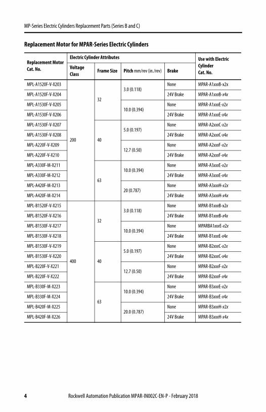
Replacement Motor for MPAR-Series Electric Cylinders
Replacement MotorCat. No.
Electric Cylinder Attributes Use with Electric Cylinder Cat. No.
Voltage Class
Frame Size Pitch mm/rev (in./rev) Brake
MPL-A1520F-V-X203
200
32
3.0 (0.118)None MPAR-A1xxxB-x2x
MPL-A1520F-V-X204 24V Brake MPAR-A1xxxB-x4x
MPL-A1530F-V-X20510.0 (0.394)
None MPAR-A1xxxE-x2x
MPL-A1530F-V-X206 24V Brake MPAR-A1xxxE-x4x
MPL-A1530F-V-X207
40
5.0 (0.197)None MPAR-A2xxxC-x2x
MPL-A1530F-V-X208 24V Brake MPAR-A2xxxC-x4x
MPL-A220F-V-X20912.7 (0.50)
None MPAR-A2xxxF-x2x
MPL-A220F-V-X210 24V Brake MPAR-A2xxxF-x4x
MPL-A330F-M-X211
63
10.0 (0.394)None MPAR-A3xxxE-x2x
MPL-A330F-M-X212 24V Brake MPAR-A3xxxE-x4x
MPL-A420F-M-X21320 (0.787)
None MPAR-A3xxxH-x2x
MPL-A420F-M-X214 24V Brake MPAR-A3xxxH-x4x
MPL-B1520F-V-X215
400
32
3.0 (0.118)None MPAR-B1xxxB-x2x
MPL-B1520F-V-X216 24V Brake MPAR-B1xxxB-x4x
MPL-B1530F-V-X21710.0 (0.394)
None MPARBA1xxxE-x2x
MPL-B1530F-V-X218 24V Brake MPAR-B1xxxE-x4x
MPL-B1530F-V-X219
40
5.0 (0.197)None MPAR-B2xxxC-x2x
MPL-B1530F-V-X220 24V Brake MPAR-B2xxxC-x4x
MPL-B220F-V-X22112.7 (0.50)
None MPAR-B2xxxF-x2x
MPL-B220F-V-X222 24V Brake MPAR-B2xxxF-x4x
MPL-B330F-M-X223
63
10.0 (0.394)None MPAR-B3xxxE-x2x
MPL-B330F-M-X224 24V Brake MPAR-B3xxxE-x4x
MPL-B420F-M-X22520.0 (0.787)
None MPAR-B3xxxH-x2x
MPL-B420F-M-X226 24V Brake MPAR-B3xxxH-x4x
4 Rockwell Automation Publication MPAR-IN002C-EN-P - February 2018
MP-Series Electric Cylinders Replacement Parts (Series B and C)
Replacement Actuator
Replacement ActuatorCat. No.
Electric Cylinder Attributes
Frame Size
Pitchmm/rev (in./rev)
Stroke Length mm (in.)Use with Electric Cylinder Cat. No.
MPAR-X1100B
32
3.0 (0.118)
100 MPAR-x1xxxB-xxx
MPAR-X1200B 200 MPAR-x1xxxB-xxx
MPAR-X1300B 300 MPAR-x1xxxB-xxx
MPAR-X1400B 400 MPAR-x1xxxB-xxx
MPAR-X1100E
10.0 (0.394)
100 MPAR-x1xxxE-xxx
MPAR-X1200E 200 MPAR-x1xxxE-xxx
MPAR-X1300E 300 MPAR-x1xxxE-xxx
MPAR-X1400E 400 MPAR-x1xxxE-xxx
MPAR-X2100C
40
5.0 (0.197)
100 MPAR-x2xxxC-xxx
MPAR-X2200C 200 MPAR-x2xxxC-xxx
MPAR-X2300C 300 MPAR-x2xxxC-xxx
MPAR-X2400C 400 MPAR-x2xxxC-xxx
MPAR-X2600C 600 MPAR-x2xxxC-xxx
MPAR-X2100F
12.7 (0.50)
100 MPAR-x2xxxF-xxx
MPAR-X2200F 200 MPAR-x2xxxF-xxx
MPAR-X2300F 300 MPAR-x2xxxF-xxx
MPAR-X2400F 400 MPAR-x2xxxF-xxx
MPAR-X2600F 600 MPAR-x2xxxF-xxx
MPAR-X3100E
63
10.0 (0.344)
100 MPAR-x3xxxE-xxx
MPAR-X3200E 200 MPAR-x3xxxE-xxx
MPAR-X3300E 300 MPAR-x3xxxE-xxx
MPAR-X3400E 400 MPAR-x3xxxE-xxx
MPAR-X3600E 600 MPAR-x3xxxE-xxx
MPAR-X3800E 800 MPAR-x3xxxE-xxx
MPAR-X3100H
20.0 (0.787)
100 MPAR-x3xxxH-xxx
MPAR-X3200H 200 MPAR-x3xxxH-xxx
MPAR-X3300H 300 MPAR-x3xxxH-xxx
MPAR-X3400H 400 MPAR-x3xxxH-xxx
MPAR-X3600H 600 MPAR-x3xxxH-xxx
MPAR-X3800H 800 MPAR-x3xxxH-xxx
Rockwell Automation Publication MPAR-IN002C-EN-P - February 2018 5
MP-Series Electric Cylinders Replacement Parts (Series B and C)
Before You BeginBefore you begin, use the Catalog Number Explanation to verify that the replacement parts match the electric cylinder that you are attempting to repair. Read through the procedure before you begin a repair or replacement.
Replace Inline-mount Electric Cylinder Motor This procedure applies to Bulletin MPAR-xxxxxx-xxA electric cylinders.
Follow these steps to replace the motor.
1. Disconnect motor and feedback cables.
2. Remove the four screws that secure the motor to the motor flange.
3. Remove the screw from the coupling hub on the motor shaft.
4. Remove the coupling hub from the motor shaft.
5. Clean the replacement motor shaft with a soft cloth and isopropyl alcohol.
6. Position the coupling hub on the shaft of the replacement motor.
Use the dimension from the table on shown in table.
7. Torque the coupling screw to the value on shown in table.
IMPORTANT Apply Loctite 222 to screws ≤ M4 and Loctite 242 for screws ≥ M5 during assembly steps.
Cat. No.Xmm (in.)
Torque N•m (lb•in)
MPAR-x1xxxB-xxA18.0 (0.71)(1)
(1) Tolerance is ± 0.3 mm (0.01 in.).
4.0 (35.4)MPAR-x1xxxE-xxA
MPAR-x2xxxC-xxA 19.1 (0.75)(1)
MPAR-x2xxxF-xxA 20.7 (0.81)(1)
MPAR-x3xxxE-xxA 31.1(1.22)(2)
(2) Tolerance is ± 0.7 mm (0.03 in.).
8.0 (70.8)MPAR-x3xxxH-xxA 38.5 (1.52)(2)
Motor Actuator CylinderX
6 Rockwell Automation Publication MPAR-IN002C-EN-P - February 2018
MP-Series Electric Cylinders Replacement Parts (Series B and C)
8. Align the coupling, the motor, and the actuator cylinder, then push them together.
9. Attach the motor to the motor mount flange by using all four screws.
10. Torque the screws as follows.
Replace Inline-mount Electric Cylinder Coupling or Actuator CylinderThis procedure applies to Bulletin MPAR-xxxxxx-xxA electric cylinders.
Follow these steps to replace the coupling or actuator cylinder.
1. Disconnect the motor and feedback cables.
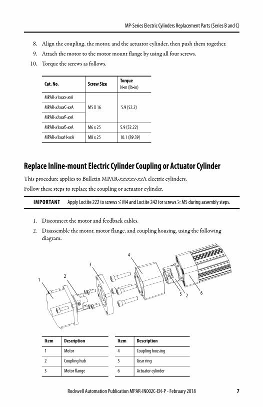
2. Disassemble the motor, motor flange, and coupling housing, using the following diagram.
Cat. No. Screw SizeTorque N•m (lb•in)
MPAR-x1xxxx-xxA
M5 X 16 5.9 (52.2)MPAR-x2xxxC-xxA
MPAR-x2xxxF-xxA
MPAR-x3xxxE-xxA M6 x 25 5.9 (52.22)
MPAR-x3xxxH-xxA M8 x 25 10.1 (89.39)
IMPORTANT Apply Loctite 222 to screws ≤ M4 and Loctite 242 for screws ≥ M5 during assembly steps.
Item Description Item Description
1 Motor 4 Coupling housing
2 Coupling hub 5 Gear ring
3 Motor flange 6 Actuator cylinder
12
3
4
2 65
Rockwell Automation Publication MPAR-IN002C-EN-P - February 2018 7
MP-Series Electric Cylinders Replacement Parts (Series B and C)
Replace Only the CouplingIf you are replacing the coupling only, follow these steps. If replacing the actuator cylinder, go to Replace Only the Actuator Cylinder on page 10.
1. Remove the coupling hubs from the motor and actuator.
2. Pull apart the new coupling.
3. Insert the new gear ring in one of the coupling hubs.
4. Using the table on page 9, position the coupling hub with the diameter that matches the motor shaft on the motor shaft.
5. Using the table page 9, position the coupling hub with the diameter that matches the actuator cylinder shaft on the actuator cylinder shaft.
Gear Ring
Coupling Hubs
Actuator Cylinder
Motor
8 Rockwell Automation Publication MPAR-IN002C-EN-P - February 2018
MP-Series Electric Cylinders Replacement Parts (Series B and C)
6. Tighten the clamping screws on both the coupling hubs to the torque shown.
Continue with Assemble the Electric Cylinder on page 10.
Cat. No.Xmm (in.)
Ymm (in.)
MPAR-x1xxxB-xxA18.0 (0.71)(1) 19.7 (0.76)(1)
(1) Tolerance is ± 0.3 mm (0.01 in.).
MPAR-x1xxxE-xxA
MPAR-x2xxxC-xxA 19.1 (0.75)(1) 18.7 (0.74)(1)
MPAR-x2xxxF-xxA 20.7 (0.81)(1) 17.7 (0.70)(1)
MPAR-x3xxxE-xxA 31.1 (1.22)(2) 23.5 (0.93)(2)
(2) Tolerance is ± 0.7 mm (0.03 in.).
MPAR-x3xxxH-xxA 38.5 (1.52)(2) 24.5 (0.94)(2)
Cat. No.Torque N•m (lb•in)
MPAR-x1xxxB-xxA
4.0 (35.4)MPAR-x1xxxE-xxA
MPAR-x2xxxC-xxA
MPAR-x2xxxF-xxA
MPAR-x3xxxE-xxA8.0 (70.8)
MPAR-x3xxxH-xxA
Motor XY
Actuator Cylinder
Rockwell Automation Publication MPAR-IN002C-EN-P - February 2018 9
MP-Series Electric Cylinders Replacement Parts (Series B and C)
Replace Only the Actuator Cylinder
1. Remove the coupling hub from the actuator cylinder.
2. Remove the screw from the coupling hub.
3. Position the coupling hub on the shaft of the actuator cylinder.
Use the dimension that is shown on the table in step 5 on page 8.
4. Tighten the coupling hub screw to the torque shown on the table in step on page 9.
Continue with Assemble the Electric Cylinder on page 10.
Assemble the Electric Cylinder
1. Attach the coupling housing by using four screws.
2. Torque the screws as shown in this table.
Cat. No. Screw SizeTorque N•m (lb•in)
MPAR-x1xxxx-xxA
M6 x 30 4.0 (35.40)MPAR-x2xxxC-xxA
MPAR-x2xxxF-xxA
MPAR-x3xxxE-xxAM8 x 40 10.1 (89.39)
MPAR-x3xxxH-xxA
Coupling Housing
Actuator Cylinder
10 Rockwell Automation Publication MPAR-IN002C-EN-P - February 2018
MP-Series Electric Cylinders Replacement Parts (Series B and C)
3. Attach the motor flange by using the required number of screws.
See table in following the step for the screw quantity.
4. Torque the screws as shown in this table.
5. Align the coupling, the motor, and the actuator cylinder and push them together.
6. Attach the motor to the motor mount flange by using all four screws.
Rockwell Automation Publication MPAR-IN002C-EN-P - February 2018 11
MP-Series Electric Cylinders Replacement Parts (Series B and C)
7. Torque screws as follows.
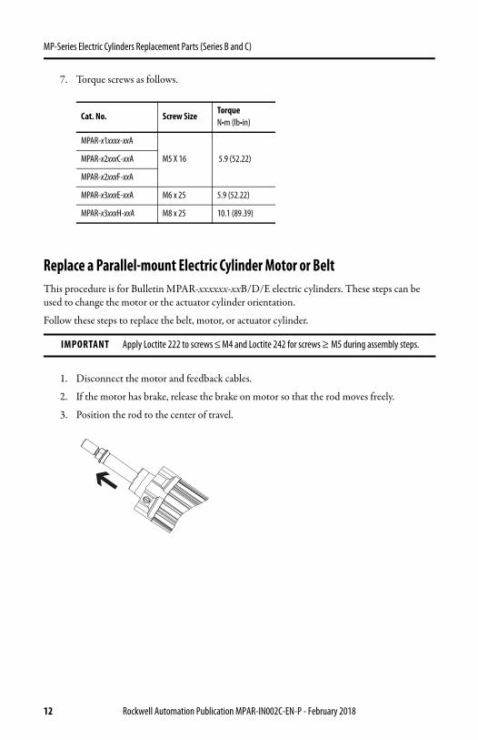
Replace a Parallel-mount Electric Cylinder Motor or BeltThis procedure is for Bulletin MPAR-xxxxxx-xxB/D/E electric cylinders. These steps can be used to change the motor or the actuator cylinder orientation.
Follow these steps to replace the belt, motor, or actuator cylinder.
1. Disconnect the motor and feedback cables.
2. If the motor has brake, release the brake on motor so that the rod moves freely.
3. Position the rod to the center of travel.
Cat. No. Screw SizeTorque N•m (lb•in)
MPAR-x1xxxx-xxA
M5 X 16 5.9 (52.22)MPAR-x2xxxC-xxA
MPAR-x2xxxF-xxA
MPAR-x3xxxE-xxA M6 x 25 5.9 (52.22)
MPAR-x3xxxH-xxA M8 x 25 10.1 (89.39)
IMPORTANT Apply Loctite 222 to screws ≤ M4 and Loctite 242 for screws ≥ M5 during assembly steps.
12 Rockwell Automation Publication MPAR-IN002C-EN-P - February 2018
MP-Series Electric Cylinders Replacement Parts (Series B and C)
4. Remove the cover from belt housing.
5. Loosen, but do not remove the four hex screws that hold the actuator cylinder to the baseplate.
6. Loosen the belt tension screw.
ATTENTION: Exposed parts that move can cause severe injury. Do not operate the electric cylinder without the cover in place. Follow the lock-out procedures before servicing the machine.
Belt Housing
Motor Mount Screw (4X)
Belt Tension Screw
Actuator Cylinder Hex Screw (X4)
Rockwell Automation Publication MPAR-IN002C-EN-P - February 2018 13
MP-Series Electric Cylinders Replacement Parts (Series B and C)
7. Remove the four socket head cap screws that secure the motor to the baseplate.
8. Angle the motor away from the actuator cylinder and remove the belt.
14 Rockwell Automation Publication MPAR-IN002C-EN-P - February 2018
MP-Series Electric Cylinders Replacement Parts (Series B and C)
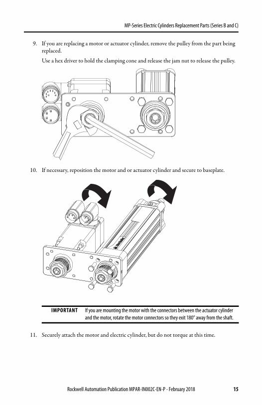
9. If you are replacing a motor or actuator cylinder, remove the pulley from the part being replaced.
Use a hex driver to hold the clamping cone and release the jam nut to release the pulley.
10. If necessary, reposition the motor and or actuator cylinder and secure to baseplate.
11. Securely attach the motor and electric cylinder, but do not torque at this time.
IMPORTANT If you are mounting the motor with the connectors between the actuator cylinder and the motor, rotate the motor connectors so they exit 180° away from the shaft.
Rockwell Automation Publication MPAR-IN002C-EN-P - February 2018 15
MP-Series Electric Cylinders Replacement Parts (Series B and C)
12. Reinstall the pulley on the new part.
Set height and torque the motor jam nut to values shown in this table.
13. Remove motor socket-head cap screws.
14. Position motor as shown in step 8 and slip on new belt.
15. Attach the motor to the baseplate by using four socket head cap screws.
Torque the motor socket-head cap screws. to values shown in this table.
16. Secure, but do not tighten the actuator cylinder with four hex screws.
17. Tighten belt tension screw.
This table shows the recommended frequency values.
Cat. No.Pulley Heightmm (in.)
Jam NutTorqueN•m (lb•in)
MPAR-x1xxxx-xxB/D/E6.5…7 (0.26…0.28) M16 x 1.5 12 (106.21)
MPAR-x3xxxE-xxB/D/E7.5…8 (0.30…0.32) M30 x 1.5 70 (619.55)
MPAR-x3xxxH-xxB/D/E
Cat. No.Screw Size
Torque N•m (lb•in)
MPAR-x1xxxB-xxB/D/E
M5 x 16 5.9 (52.2)MPAR-x1xxxE-xxB/D/E
MPAR-x2xxxC-xxB/D/E
MPAR-x2xxxF-xxB/D/E
MPAR-x3xxxE-xxB/D/E M6 x 20 5.9 (52.22)
MPAR-x3xxxH-xxB/D/E M8 x 20 10.1 (89.39)
Cat. No.Recommend Belt TensionN (lbf)
FrequencyHz
MPAR-x1xxxx-xxB/D/E32…35 (7.2…7.9)
242…254
MPAR-x2xxxC-xxB/D/E 242…254
MPAR-x2xxxF-xxB/D/E 57…63 (12.8…14.2) 152…160
MPAR-x3xxxx-xxB/D/E 108…119 (24.3…26.8) 161…168
16 Rockwell Automation Publication MPAR-IN002C-EN-P - February 2018
MP-Series Electric Cylinders Replacement Parts (Series B and C)
18. Torque the actuator cylinder screws to values shown in this table.
19. Secure the cover to the belt housing with five socket head cap screws.
IMPORTANT A low pretension force is better than a high pretension force.
Excessive pretension on the belt results in:
• impermissible radial loads causing shaft to break• increased wear in the axis and motor gearings• reduction of the service life of the belt
Cat. No.Hex Screw TorqueN•m (lb•in)
MPAR-x1xxxx-xxB/D/E
5.9 (52.22)MPAR-x2xxxC-xxB/D/E
MPAR-x2xxxF-xxB/D/E
MPAR-x3xxxx-xxB/D/E 10.1 (89.39)
Cat. No. Screw SizeTorqueN•m (lb•in)
MPAR-x1xxxx-xxB/D/EM6x45
5.9 (52.22)MPAR-x2xxxC-xxB/D/E
MPAR-x2xxxF-xxB/D/E M6x60
MPAR-x3xxxx-xxB/D/E M8x70 10.1 (89.39)
Rockwell Automation Publication MPAR-IN002C-EN-P - February 2018 17
MP-Series Electric Cylinders Replacement Parts (Series B and C)
Additional ResourcesThese documents contain additional information concerning related products from Rockwell Automation.
You can view or download publications at http://www.rockwellautomation.com/global/literature-library/overview.page. To order paper copies of technical documentation, contact your local Allen-Bradley distributor or Rockwell Automation sales representative.
Resource Description
MP-Series Electric Cylinders Installation Instructions, publication MPAR-IN001 Information on how to install MP-Series electric cylinders
MP-Series Brushless Servo Motor Installation Instructions, publication MP-IN001
Information on how to install, medium frame (100…165 mm) MP-Series low-inertia motors
MP-Series Brushless Servo Motor Installation Instructions, publication MP-IN006
Information on how to install small frame (<75 mm) MP-Series low-inertia motors
MP-Series Electric Cylinders Replacement Parts (Series B and C)
Notes:
Rockwell Automation Publication MPAR-IN002C-EN-P - February 2018 19
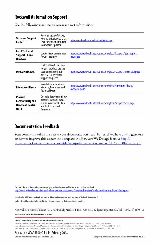
Rockwell Automation SupportUse the following resources to access support information.
Documentation FeedbackYour comments will help us serve your documentation needs better. If you have any suggestions on how to improve this document, complete the How Are We Doing? form at http://literature.rockwellautomation.com/idc/groups/literature/documents/du/ra-du002_-en-e.pdf.
Technical Support Center
Knowledgebase Articles, How-to Videos, FAQs, Chat, User Forums, and Product Notification Updates.
Allen-Bradley, MP-Series, Rockwell Software, and Rockwell Automation are trademarks of Rockwell Automation, Inc.
Trademarks not belonging to Rockwell Automation are property of their respective companies.
Rockwell Otomasyon Ticaret A.Ş., Kar Plaza İş Merkezi E Blok Kat:6 34752 İçerenköy, İstanbul, Tel: +90 (216) 5698400
Rockwell Automation maintains current product environmental information on its website athttp://www.rockwellautomation.com/rockwellautomation/about-us/sustainability-ethics/product-environmental-compliance.page.