229
Model S-C3 Machine Code: B262/B280/B292/B293 SERVICE MANUAL June 30th, 2006 Subject to change
| Date post: | 28-Mar-2016 |
| Category: |
Documents |
| Upload: | jack-hunter |
| View: | 223 times |
| Download: | 0 times |

Model S-C3 Machine Code:
B262/B280/B292/B293
SERVICE MANUAL
June 30th, 2006 Subject to change

Safety Notice
Important Safety Notices
Prevention of Physical Injury
1. Be sure that the power cord is unplugged before disassembling or assembling parts of the copier orperipherals.
2. The wall outlet should be near the copier and easily accessible.
3. Note that electrical voltage is supplied to some components of the copier and the paper tray unit evenwhile the main power switch is off.
4. If you start a job before the copier completes the warm-up or initializing period, keep hands awayfrom the mechanical and electrical components until job execution has started. The copier will startmaking copies as soon as warm-up or initialization is finished.
5. The inside and the metal parts of the fusing unit become extremely hot while the copier is operating.Be careful to avoid touching those components with your bare hands.
Health Safety Conditions
Toner and developer are nontoxic, but getting either of these into your eyes may cause temporary eyediscomfort. Try to remove with eye drops or flush with water. If material remains in eye or if discomfortcontinues, get medical attention.
Observance of Electrical Safety Standards
The copier and its peripherals must be installed and maintained by a customer service representative whohas completed the training course on those relevant models.
• Keep the machine away from flammable liquids, gases, and aerosols. A fire or an explosion mightoccur if this precaution is not observed.
Safe and Ecological Disposal
1. Do not incinerate toner bottles or used toner. Toner dust may ignite suddenly if exposed to an openflame.
2. Dispose of used toner, developer, and organic photoconductors in accordance with local regulations.(These are nontoxic supplies.)
1

3. Dispose of replaced parts in accordance with local regulations.
Laser Safety
The Center for Devices and Radiological Health (CDRH) prohibits the repair of laser-based optical unitsin the field. The optical housing unit can only be repaired in a factory or at a location with the requisiteequipment. The laser subsystem is replaceable in the field by a qualified Customer Engineer. The laserchassis is not repairable in the field. Customer engineers are therefore directed to return all chassis andlaser subsystems to the factory or service depot when replacement of the optical subsystem is required.
• Use of controls not specified in this manual, or performance of adjustments or procedures not specifiedin this manual, may result in hazardous radiation exposure.
WARNING FOR LASER UNIT
• Turn off the main switch before attempting any of the procedures in the Laser Unit section. Laserbeams can seriously damage your eyes.
CAUTION MARKING:
2

Symbols and AbbreviationsThis manual uses several symbols and abbreviations. The meaning of those symbols and abbreviations isas follows:
* See or Refer to
Clip ring
E-ring
Screw
Connector
Clamp
SEF Short Edge Feed
LEF Long Edge Feed
Core Technology manual
Cautions, Notes, etc.
The following headings provide special information:
• FAILURE TO OBEY WARNING INFORMATION COULD RESULT IN SERIOUS INJURY OR DEATH.
• Obey these guidelines to ensure safe operation and prevent minor injuries.
• This information provides tips and advice about how to best service the machine.
3

TABLE OF CONTENTSSafety Notice......................................................................................................................................................1
Important Safety Notices..........................................................................................................................1
Laser Safety.....................................................................................................................................................2
Symbols and Abbreviations...............................................................................................................................3
1. Installation
Installation Cautions.........................................................................................................................................11
Installation Requirements.................................................................................................................................12
Environment..................................................................................................................................................12
MACHINE LEVEL.........................................................................................................................................12
Minimum Operational Space Requirements.............................................................................................13
Power Requirements....................................................................................................................................14
Copier...............................................................................................................................................................15
Accessory Check..........................................................................................................................................15
Installation Procedure..................................................................................................................................16
Paper Tray Unit.................................................................................................................................................21
Accessory Check..........................................................................................................................................21
Installation Procedure..................................................................................................................................21
Paper Tray Unit Heater....................................................................................................................................23
Accessory Check..........................................................................................................................................23
Installation Procedure..................................................................................................................................24
ARDF (B872)....................................................................................................................................................31
Accessory Check..........................................................................................................................................31
Installation Procedure..................................................................................................................................31
DDST Unit (B880/893)..................................................................................................................................38
Accessory Check..........................................................................................................................................38
Installation Procedure..................................................................................................................................39
2. Preventive Maintenance
PM Tables.........................................................................................................................................................43
How to Clear the PM Counter.........................................................................................................................45
3. Replacement and Adjustment
Precautions........................................................................................................................................................47
General.........................................................................................................................................................47
Halogen-free Cable....................................................................................................................................47
4

Special Tools and Lubricants...........................................................................................................................48
Exterior Covers and Operation Panel............................................................................................................49
Rear Cover...................................................................................................................................................49
Copy Tray.....................................................................................................................................................49
Scale Plate....................................................................................................................................................50
Operation Panel and Upper Covers..........................................................................................................51
Right Door.....................................................................................................................................................52
Bypass Tray..................................................................................................................................................52
Platen Cover Sensor....................................................................................................................................53
Scanner Unit.....................................................................................................................................................54
Exposure Glass............................................................................................................................................54
Lens Block.....................................................................................................................................................55
Exposure Lamp, Lamp Stabilizer Board.....................................................................................................55
Scanner Motor.............................................................................................................................................56
Scanner HP Sensor......................................................................................................................................58
Scanner alignment adjustment....................................................................................................................58
Fusing................................................................................................................................................................60
Fusing Unit....................................................................................................................................................60
Exit Sensor....................................................................................................................................................61
Hot Roller Stripper Pawls.............................................................................................................................61
Hot Roller & Fusing Lamp............................................................................................................................62
Thermoswitches and Thermistor..................................................................................................................64
Pressure Roller..............................................................................................................................................65
Checking the NIP band...............................................................................................................................66
PCU and Quenching Lamp.............................................................................................................................67
PCU...............................................................................................................................................................67
Quenching Lamp..........................................................................................................................................68
Exhaust Fan and Main Motor.........................................................................................................................69
Exhaust Fan..................................................................................................................................................69
Main Motor..................................................................................................................................................70
Paper Feed........................................................................................................................................................71
Paper Feed Roller and Friction Pad............................................................................................................71
Paper End Sensor.........................................................................................................................................72
5

Registration Sensor......................................................................................................................................72
Bypass Paper End Sensor...........................................................................................................................73
Bypass Feed Roller......................................................................................................................................74
Bypass Feed Clutch and Friction Pad.........................................................................................................75
Paper Feed and Registration Clutches.......................................................................................................76
Image Transfer..................................................................................................................................................78
Transfer Roller..............................................................................................................................................78
ID Sensor and Duplex Roller.......................................................................................................................79
Discharge plate............................................................................................................................................80
BICU and Controller Board ............................................................................................................................81
BICU..............................................................................................................................................................81
Controller Board (B280/B293 models only)...........................................................................................82
Other Replacements.........................................................................................................................................85
Duplex Motor...............................................................................................................................................85
High-Voltage Power Supply Board ...........................................................................................................86
PSU................................................................................................................................................................87
Contact-Release Solenoid...........................................................................................................................88
Toner Supply Clutch....................................................................................................................................88
Laser Unit..........................................................................................................................................................90
Location of the Caution Decal....................................................................................................................90
Laser Unit......................................................................................................................................................90
LD Unit and Polygon Mirror Motor............................................................................................................91
Adjusting Copy Image Area............................................................................................................................92
Printing..........................................................................................................................................................92
Scanning.......................................................................................................................................................94
DF Image Adjustment...................................................................................................................................97
4. Troubleshooting
Service Call Conditions...................................................................................................................................99
Summary.......................................................................................................................................................99
SC Code Descriptions.................................................................................................................................99
Electrical Component Troubleshooting........................................................................................................108
Sensor/Switch Open Errors.....................................................................................................................108
Blown Fuse Conditions..............................................................................................................................109
6

BICU LED Display......................................................................................................................................110
5. Service Tables
Service Program.............................................................................................................................................111
Using SP and SSP Modes.........................................................................................................................111
Copier Service Program Mode Tables....................................................................................................113
ID Sensor Error Analysis (SP2-221)........................................................................................................139
Memory Clear...........................................................................................................................................140
INPUT CHECK (SP5-803)........................................................................................................................141
OUTPUT CHECK (SP5-804)....................................................................................................................143
SERIAL NUMBER INPUT (SP5-811-001)..............................................................................................144
NVRAM DATA UPLOAD/DOWNLOAD (SP5-824/825)..................................................................145
Firmware Update Procedure....................................................................................................................147
TEST PATTERN PRINT (SP5-902-001)...................................................................................................149
SMC Print (SP5-990)................................................................................................................................151
Printer Service Program Mode Table.......................................................................................................152
Scanner Service Program Mode Table...................................................................................................152
6. Detailed Section Descriptions
Overview........................................................................................................................................................153
Component Layout....................................................................................................................................153
Electrical Components..............................................................................................................................155
Paper Path......................................................................................................................................................157
Drive Layout...................................................................................................................................................158
Block Diagram: PCBs and Components......................................................................................................159
Main PCBs......................................................................................................................................................160
SBU (SENSOR BOARD UNIT).................................................................................................................160
Copy Process.................................................................................................................................................162
Overview....................................................................................................................................................162
Scanning.........................................................................................................................................................164
Overview....................................................................................................................................................164
Scanner Drive............................................................................................................................................165
Image Processing...........................................................................................................................................166
Overview....................................................................................................................................................166
Image Processing Path..............................................................................................................................167
7

Original Modes.........................................................................................................................................167
Image Processing Steps for Each Mode..................................................................................................170
Mode Adjustments.....................................................................................................................................171
Laser Exposure...............................................................................................................................................172
Overview....................................................................................................................................................172
LD Safety Switches....................................................................................................................................173
Photoconductor Unit (PCU)...........................................................................................................................174
Overview....................................................................................................................................................174
DRUM Drive...............................................................................................................................................175
Drum Charge.................................................................................................................................................176
Overview....................................................................................................................................................176
Charge Roller Voltage Correction...........................................................................................................177
Charge Roller Cleaning............................................................................................................................178
Detection of New PCU..............................................................................................................................178
Development..................................................................................................................................................180
Overview....................................................................................................................................................180
Development Bias......................................................................................................................................181
Toner Supply..............................................................................................................................................181
Toner density control.................................................................................................................................182
Toner Supply If Sensor Reading is abnormal .........................................................................................183
Detection of Toner Near End and Toner End .........................................................................................184
Drum Cleaning and Toner Recycling...........................................................................................................185
Paper Feed.....................................................................................................................................................186
Overview....................................................................................................................................................186
Paper Feed Drive Mechanism..................................................................................................................187
Paper Feed and Separation.....................................................................................................................189
Paper Lift Mechanism................................................................................................................................189
Paper End Detection..................................................................................................................................190
Image Transfer and Paper Separation.........................................................................................................192
Overview....................................................................................................................................................192
Image Transfer Current Timing.................................................................................................................192
Transfer Roller Cleaning...........................................................................................................................193
Image Fusing and Paper Exit........................................................................................................................194
8

Overview....................................................................................................................................................194
Hot Roller Drive.........................................................................................................................................195
Pressure Roller............................................................................................................................................196
Pressure Release........................................................................................................................................196
Separation.................................................................................................................................................197
Fusing Temperature Control.....................................................................................................................197
Duplex Unit.....................................................................................................................................................201
Important Components.............................................................................................................................201
Duplex Printing Process.............................................................................................................................202
Energy Saver Modes.....................................................................................................................................205
Overview....................................................................................................................................................205
AOF............................................................................................................................................................206
Timers.........................................................................................................................................................206
Recovery....................................................................................................................................................206
GDI Controller...............................................................................................................................................207
Overview....................................................................................................................................................207
Controller Functions...................................................................................................................................209
Scanner Functions.....................................................................................................................................210
Network Interface.....................................................................................................................................211
USB.............................................................................................................................................................212
NVRAM on the GDI Controller................................................................................................................214
7. Specifications
General Specifications..................................................................................................................................215
Copier........................................................................................................................................................215
Printer..........................................................................................................................................................217
Scanner......................................................................................................................................................218
ARDF...........................................................................................................................................................218
Paper Tray Unit..........................................................................................................................................219
Supported Paper Sizes..................................................................................................................................221
Original Paper Sizes.................................................................................................................................221
Paper Feed.................................................................................................................................................222
Machine Configuration.................................................................................................................................225
Basic Model (B262/B292).....................................................................................................................225
9

GDI Model (B280/B293).......................................................................................................................226
10

1. Installation
Installation Cautions
• Before installing an optional unit, do the following:
• If there is a printer option on the machine, print out all data in the printer buffer.
• Turn off the main switch and disconnect the power cord, the telephone line, and the networkcable.
11
1

Installation Requirements
Environment
–Temperature and Humidity Chart–
• Temperature Range: 10°C to 32°C (50°F to 89.6°F)
• Humidity Range: 15% to 80% RH
• Ambient Illumination: Less than 1,500 lux (Do not expose to direct sunlight.)
• Ventilation: Room air should turn over at least 3 times/hr/person
• Ambient Dust: Less than 0.1 mg/m3
• Do not install the machine where it will be exposed to direct sunlight or to direct airflow (from a fan,air conditioner, air cleaner, etc.).
• Do not install the machine where it will be exposed to corrosive gas.
• Place the machine on a firm and level base.
• Do not install the machine where it may be subjected to strong vibration.
MACHINE LEVEL
Front to back: Within 5 mm (0.2") of level
1. Installation
12
1

Right to left: Within 5 mm (0.2") of level
Minimum Operational Space Requirements
Place the machine near the power source, providing clearance as shown.
A: Front – 750 mm (29.6")B: Left – 100 mm (3.9")C: Rear – 105 mm (4.1")D: Right – 230 mm (9.0")
E: Depth – 450 mm (17.7")
F: Width – 485 mm (19.1")
• The 750-mm front space indicated above is sufficient to allow the paper tray to be pulled out. Addi-tional space is required to allow an operator to stand at the front of the machine.
Installation Requirements
13
1

• Actual minimum space requirement for left, rear, and right sides is 10mm (0.4") each, but note thatthis will not allow room for opening of the bypass tray, right door, platen cover, or ARDF unit.
Power Requirements
• Make sure that the wall outlet is near the machine and easily accessible. After completing installation,make sure the plug fits firmly into the outlet.
• Avoid multiple connections to the same power outlet.
• Be sure to ground the machine.
Input voltage:
North America: 110 – 120 V, 60 Hz, 8 A
Europe: 220 – 240 V, 50/60 Hz, 4 A
Image quality guaranteed at rated voltage ± 10%.
Operation guaranteed at rated voltage ± 15%.
1. Installation
14
1

Copier
Accessory Check
Basic Model
Description Q’ty
CD-ROM (Copy Reference) (-17) 1
CD-ROM
(Printer Reference/Scanner Reference/Copy Reference) (-21)1
About This Machine (-17) 1
Troubleshooting (-17) 1
Language Kit (-26) 1
EU Safety Sheet (-26, -67) 1
NECR (-17) 1
CCC Decal (-21) 1
Paper Size Decal 1
Warranty Sheet (Chinese) (-21) 1
Sheet - Name - Tel (-21) 1
GDI Model
Description Q’ty
General Settings Guide (-29) 1
Copy Reference (-29) 1
Quick Copy Guide (-29) 1
Quick Printer/Scanner Guide (-29) 1
CD-ROM (Printer Reference/Scanner Reference) (-26, -67) 1
Copier
15
1

CD-ROM (Driver: Printer/Scanner and Printer Reference/Scanner Reference) (-29) 1
EU Safety Sheet (-26, -67) 1
NECR (-17) 1
Paper Size Decal 1
Sheet - EULA (-26, -29, 67) 1
Caution Decal (-26, -29, 67) 1
Ferrite Core (B293-26, B293-67) 1
Installation Procedure
• Make sure that the copier remains unplugged during installation.
1. Remove the strips of tape.
2. Remove the bag [A], SMC and A3 sheet of paper [B] on the exposure glass.
1. Installation
16
1

3. Remove the spacing wedge [C].
4. Remove the three scanner lock pins. (A tag is hanging from each pin.) To remove: Grasp the base ofthe pin [D], turn the pin 90 degrees, and pull it down and out.
5. Remove the tags from the pins.
6. Break each pin off the base [D].
7. Discard the pin part [E].
8. Set each base [D] back into its original hole, turning it 90° to lock it into place. (Be sure to do this forall three pins.)
Copier
17
1

9. Open the front door [F].
10. Lift lever [G], press in on latch [H] and pull the bottle holder [I] out. (You do not need to pull it completelyout of the machine.)
11. Take a new bottle of toner, and shake it several times.
12. Remove the outer cap [J].
• Do not remove the inner cap [K].
13. Load the bottle on the holder.
• Do not forcefully turn the toner bottle on the holder. After you turn on the main power switch, thecopier sets the bottle in place.
14. Push the bottle holder back into the machine.
15. Press the latch [L] down to lock the holder.
1. Installation
18
1

16. Remove the padding [M].
17. Pull each tabbed strip [N] out of the PCU with one hand, supporting the PCU with the other.
• Do not pull both strips at the same time, as this could damage the PCU.
18. Close the front door.
19. Pull out the paper tray, and remove the tape securing the end fence in the compartment.
20. Push the bottom plate down, and then load the paper.
21. Adjust the side fences. If you load paper shorter than A4, set the end fence in the correct position.
Copier
19
1

22. Push the tray back into the copier.
23. Attach the appropriate Brand Decal to the center [O] of the front door if necessary.
24. Attach the appropriate tray number decal and paper-size decal to the paper tray [P].
25. Install optional units (if any).
26. For B293 only: Attach the ferrite core [Q] to the network cable when connecting the cable.
• The end of the ferrite core must be about 10 cm (4") from the end [R] of the cable.
27. Plug in the machine and turn on the main power switch.
28. Select the language used in the operation panel as necessary ( > Language).
29. Make a full size copy, and check if the side-to-side and leading edge registrations are correct. If theyare not, adjust the registrations.
1. Installation
20
1

Paper Tray Unit
Accessory Check
Confirm that you have these accessories.
Description Q’ty
1. Paper-size decals 1 sheet
2. Installation Procedure (for service person) 1
3. Installation Procedure (for user) 1
Installation Procedure
• Unplug the main machine's power cord before starting the following procedure.
1. Remove the tape at [A], and the tape and cardboard at [B].
2. Pull the paper tray part way out of the unit, remove the tape and cardboard at [C], and push the trayback in.
Paper Tray Unit
21
1

3. Set the machine on the paper tray unit.
4. Remove the paper tray from the paper tray unit.
5. Load paper into the paper tray. Adjust the side and end fences as necessary. If loading 81/2"x 14"paper, remove the end fence and set it into the special compartment.
6. Set the paper tray back into the paper tray unit.
7. Stick on the appropriate tray-number decal and paper-size decal, at the locations indicated in theillustration.
1. Installation
22
1

Paper Tray Unit Heater
Accessory Check
Confirm that you have the accessories listed below.
Description Q’ty
1. Grounding wire 1
2. Relay harness 1
3. Clamps 2
4. Ferrite core 1
5. Heater fastening screws 2
6. PTU fastening screws 3
7. Grounding screw 1
8. Decal for copier 1
9. Decal for paper unit 1
10. Tie wrap 1
Paper Tray Unit Heater
23
1

Installation Procedure
• Unplug the main machine's power cord before starting the following procedure.
1. Remove the paper tray unit from the copier if it is already installed.
2. Remove the paper trays from the copier and from the paper tray unit.
1. Installation
24
1

3. Remove the ground screw [1] at the rear of the paper tray unit.
4. Fasten the heater [2] and the supplied ground wire [3] to the paper tray unit ( x 3). Note that [1] isthe ground screw you removed in the previous step and [4] and [5] are the two supplied heaterfastening screws.
• Be sure to position the ground wire [3] and heater harness [6] so that they are out of the way ofthe copier when you set it onto the paper tray unit.
5. Set the copier onto the paper tray unit.
6. Screw the paper tray unit into place using three supplied PTU fastening screws.
Paper Tray Unit Heater
25
1

7. Open the front door and remove the copy tray [7] (×1).
8. Close the front door.
9. Remove the memory card cover [8] ( x 1).
10. Remove the rear cover [9] ( x 5).
1. Installation
26
1

11. For B280/B293 only: Remove the upper left cover [10].
12. For B280/B293 only: Remove the controller box [11] ( x 1, x 5).
13. Remove the support bracket [12] ( x 3).
Paper Tray Unit Heater
27
1

14. Pass the heater harness through the hole [15] at the rear of the copier.
15. Pass relay harness [16] through the opening [17] (at the rear of the PSU) and through the otheropening [15].
16. Connect the relay harness to the heater's harness [18].
17. Pull the relay harness back into the copier.
1. Installation
28
1

18. Attach the ferrite core [19] over the relay harness.
19. Push the ferrite core back so that it is over the heater's harness.
20. Wrap the heater's harness once around the ferrite core [20].
21. Locate the ferrite core at the rear [24] of the copier behind the rear clamps.
22. Secure the ferrite core with the supplied tie wrap [21].
23. Clip off the excess length of the tie wrap.
24. Connect the relay harness connector [22] to the large connector at the front center of the PSU.
25. Screw the ground wire [23] to the PSU bracket with the included grounding screw.
26. Attach the clamps [24] to the PSU bracket.
27. Attach the heater harness though the clamps.
28. Position the harness so that the front clamp is between the two bindings [25] on the harness.
29. Fasten the clamps.
30. Pull the excess length of the heater's harness out the opening at the rear.Note: Be sure that the harness passes on the side of the grounding plate at the bottom of the opening.(The front of the grounding plate must remain clear.)
31. Arrange the excess harness length so that it sits beneath the FCU cover plate.
32. Attach the caution decals to the locations shown in the illustration.
Paper Tray Unit Heater
29
1

33. Reassemble the copier.
34. Plug in the power cord, and check the operation.
1. Installation
30
1

ARDF (B872)
Accessory Check
Description Q’ty
1. Stud Screw 1
2. Screw 1
3. Clamp 1
4. DF Exposure Glass with Mylar 1
5. Left Scale Guide 1
Platen Sheet 1
Installation Procedure 1
Installation Procedure
• Unplug the main machine's power cord before starting the following procedure.
ARDF (B872)
31
1

1. Unpack the ARDF and remove the packing tape from the bottom of the ARDF body.
2. Open the right door [A].
3. Remove the connector cover [B] ( x 1) and rear cover [C] ( x 5).
1. Installation
32
1

4. Remove the left guide [D] ( x 2) and scanner left cover [E] (hook x 2).
5. Place the DF exposure glass [F] on the glass holder.
• When installing the DF exposure glass, make sure that the side of the DF exposure glass withtwo black points faces down.
• Do not hold the Mylar strip when installing the DF exposure glass.
• Make sure that there is no gap between the two Mylar strips and the scanner frame. If there isany gap between them, dust may fall into the scanner unit.
ARDF (B872)
33
1

6. Peel off the backing [G] of the double-sided tape attached to the rear side of the left scale guide [H],then install it ( x 2 removed in step 4).
7. Remove the two platen stays [I] and bracket ( x 1 each).
8. The bracket is attached to the platen stay of the rear left side. Make sure to remove the bracket at thistime.
1. Installation
34
1

9. Mount the DF [J] on the copier as shown.
10. Secure the screw [K].
11. Attach the clamp [L].
12. Connect two I/F cables [M] to the CN109 and CN110 on the BICU, and secure the ground cable[N] ( x 1, x 2).
• Make sure that the I/F cable of ARDF is clamped between the two binds [O].
• Reinstall the scanner left side cover removed in step 4.
ARDF (B872)
35
1

13. Cut the cutout [P] with nippers.
14. Reinstall the rear cover and connector cover ( x 6).
15. Close the right door.
16. Open the ARDF.
17. Place platen sheet [Q] on the exposure glass.
18. Line up the rear left corner of the platen sheet flush against corner [R] on the exposure glass.
19. Close the ARDF.
1. Installation
36
1

20. Check that the groove [S] of the ARDF is aligned with the groove [T] of the left scale on the scanner.
• The shift value between [S] and [T] must be within ± 0.5 mm.
21. Reinstall the platen sheet if both grooves are not aligned correctly.
22. Plug in and turn on the main power switch.
23. Check the ARDF operation.
24. Make a full size copy. Then check to make sure the side-to-side and leading edge registrations arecorrect. If they are not, adjust the side-to-side and leading edge registration (refer to the "DF ImageAdjustment" in the section "Replacement Adjustment").
ARDF (B872)
37
1

DDST Unit (B880/893)
Accessory Check
No. Description Q’ty
1. Controller Box 1
2. Screw M3 x 6 7
3.Printer Panel (B880: English + Symbol) 2
Printer Panel (B893: Symbol) 1
4. Ferrite Core (B880) 1
5.
CD-ROM (Printer and Scanner Driver) (-15, -17) 1
CD-ROM (Printer/Scanner Reference) (-15, -17) 1
CD-ROM (Printer/Scanner Driver and Printer/Scanner Reference) (-21) 1
6 FCC Decal (-15) 1
7 Ground Plate (B880-15, 21) 1
- General Setting Guide (-17, -21) 1
- Copy Reference (-17, -21) 1
- Quick Copy Guide (-17) 1
- Quick Printer/Scanner Guide (-17) 1
- Sheet - EULA (Chinese) (B893) 1
- Sheet - Caution (Chinese) (B893) 1
- Installation Procedure 1
1. Installation
38
1

Installation Procedure
• Unplug the main machine's power cord before starting the following procedure.
1. Open the right door [A].
2. Remove the memory card cover [B] ( x 1)
3. Remove the rear cover [C] ( x 5).
4. Remove the bracket [D] ( x 2)
5. Cut the opening [E] and [F] on the rear cover. This opening is for the USB slot and the LAN cable.
6. Remove the upper left cover [G].
DDST Unit (B880/893)
39
1

7. Install the ground plate [H] ( x 2).
• Insert the upper and lower hooks in the openings [I], and fasten the upper screw first.
8. Install the controller box [J] ( x 5).
• Insert the bracket [K] into the frame. The connector on the controller box engages with theconnector on the BICU.
9. Remove the panel cover [L].
10. Install the printer panel [M].
1. Installation
40
1

11. For the North America model only: Attach the FCC decal [N] close to the LAN cable slot of thecontroller box.
12. Reassemble the whole copier.
13. For B880 only: Attach the ferrite core [O] to the network cable and attach the cable to the copier ifa network cable is used.
• The end of the ferrite core must be about 10 cm (4") [P] from the end of the cable.
DDST Unit (B880/893)
41
1

14. Plug in the power cord, and turn on the main switch.
15. Check the operations.
1. Installation
42
1

2. Preventive Maintenance
PM TablesReset the PM counter (SP7-804-001) after doing maintenance work.
Key: AN: As necessary, C: Clean, R: Replace, I: Inspect
Every 45k Every 90k AN NOTE
OPTICS
Reflector C C Optics cloth
1st mirror C C Optics cloth
2nd mirror C C Optics cloth
3rd mirror C C Optics cloth
Platen cover C C Dry cloth
Exposure glass C C Dry cloth
Toner shield glass C C Dry cloth
DRUM AREA
PCU R Clean toner-bottle holder.
Transfer roller R
Discharge plate R
PAPER FEED
Paper feed roller R C Water or alcohol.
Friction pad R C Dry cloth
Bottom-plate pad C C Water or alcohol.
Registration roller C C Water or alcohol.
FUSING UNIT
Hot roller R
Pressure roller R
43
2

Every 45k Every 90k AN NOTE
Hot roller bearings R
Pressure-roller bush-ings
I
Inlet guide C
Outlet guide C
Hot roller stripperpawls
R
Thermistor C
Every 90k AN NOTE
ARDF
Separation roller R C Water or alcohol
Pick-up roller R C Water or alcohol
Feed roller R C Water or alcohol
White plate C Water or alcohol
DF exposure glass C Water
Rollers R0, R1, R2 C Water or alcohol
Registration sensor re-flector
C Water or alcohol
Every 120k AN NOTE
PAPER TRAY UNIT
Paper feed roller R
Bottom-plate pad C Dry cloth
Friction pad R
2. Preventive Maintenance
44
2

How to Clear the PM CounterReset the PM counter after your maintenance work.
1. Activate the SP mode.
2. Select SP7-804-001.
3. Press the EXECUTE key [A]. The message "Completed" is displayed when the program ends normally.An error message is displayed if the program ends abnormally.
4. Press the (Escape) key [B] to end the program.
How to Clear the PM Counter
45
2

2. Preventive Maintenance
46
2

3. Replacement and Adjustment
Precautions
General
• Turn off the main power switch and unplug the machine before starting replacement.
Before turning off the main power switch, check that no mechanical component is operating. Mechanicalcomponents may stop out of their home positions if you turn off the main power switch while they areoperating. The component may be damaged if you try to remove it when it is not in the home position.
Halogen-free Cable
• Use extreme caution while handling cables.
To comply with local regulations, halogen-free cables are used in this machine. Halogen-free cables areenvironment-friendly, but no stronger than conventional cables. These cables may be damaged in any ofthe following cases:
• The cable is caught between hard objects such as brackets, screws, PCBs, and exterior covers.
• The cable is rubbed on a hard object such as brackets, screws, PCBs, and exterior covers.
• The cable is scratched with a hard object such as brackets, screws, PCBs, exterior covers, screwdriv-ers, and fingernails.
47
3

Special Tools and LubricantsPart Number Description Q’ty
A1849501 Optics Adjustment Tools (2 pcs/set) 1 set
A2929500 Test Chart – S5S (10 pcs/set) 1 set
VSSM9000 Digital Multimeter – Fluke 87 1
N8036701 Flash Memory Card (4MB) 1
N8031000 Case for Flash Memory Card 1
A2579300 Grease Barrierta – S552R 1
52039502 Silicon Grease 501 1
3. Replacement and Adjustment
48
3

Exterior Covers and Operation Panel
Rear Cover
1. Open the left door [A].
2. Memory card cover [B] ( x 1)
3. Rear cover [C] ( x 5)
Copy Tray
• Make sure that the cables under the copy tray are in place before reassembling the copier. If thesecables are caught between the copy tray and the inner cover, they may be severely damaged.
Exterior Covers and Operation Panel
49
3

1. Open the front door [A].
2. Copy tray [B] ( x 1)
Reassembling
There are several cables under the front end of the copy tray. To set these cables in place, gently pull thesecables to the left-hand side (toward the PSU) and hold them there as you attach the copy tray.
Scale Plate
The scale plate is for the following models only:
• The copier/printer/scanner model (B280/B293)
• The basic model (B262)
3. Replacement and Adjustment
50
3

1. Scale plate [A] ( × 2)
Operation Panel and Upper Covers
1. Remove the ARDF (if it has been installed).
2. Rear cover (* "Rear Cover")
3. Slide the upper left cover [A] to the rear.
4. Rear scale [B] ( x 3)
5. Slide the upper right cover [C] to the rear.
6. Front left cover [D] ( x 2)
7. Operation panel [E] (x 4, x 1)
8. Front right cover [F]
Exterior Covers and Operation Panel
51
3

Right Door
1. Open the right door [A].
2. Release the strap [B].
3. Right door ( × 1)
Bypass Tray
3. Replacement and Adjustment
52
3

1. Press the stopper rails [A] inward.
Platen Cover Sensor
1. Rear cover (* "Rear Cover")
2. Rear scale (* "Operation Panel and Upper Covers")
3. Platen cover sensor [A] (× 1, hook)
Exterior Covers and Operation Panel
53
3

Scanner UnitTo clean the mirrors and lenses, use a blower brush or wet cotton.
Exposure Glass
To clean the exposure glass, use alcohol or glass cleaner.
Non-ARDF machines
1. Rear cover (* "Rear Cover")
2. Scale plate (* "Operation Panel and Upper Covers")
3. Exposure glass [A]
ARDF-equipped machines
1. Rear cover (* "Rear Cover")
2. Rear scale, upper right cover (* "Operation Panel and Upper Covers")
3. Exposure glass [A]
Reassembling
Make sure that the marking on the glass is at the rear left corner, and that the left edge of the glass is alignedflush against the support ridge [B] on the frame.
Adjustment
When replacing the white plate, conduct the Scan Auto Adjustment (*SP4-428-001).
3. Replacement and Adjustment
54
3

Lens Block
• Do not disassemble the lens block. The lens block is precision adjusted before shipment.
• Do not touch the screws on the CCD. The CCD is precision adjusted before shipment.
1. Exposure glass (* "Exposure Glass")
2. Front left cover, operation panel (* "Operation Panel and Upper Covers")
3. Release the cable from the four clamps [A].
4. Lens block [B] ( × 4, 1 flat cable)
• Do not loosen the paint-locked screws holding the lens unit in place.
• After installing a new lens block, carry out copy adjustments (* "Adjusting Copy Image Area").
Exposure Lamp, Lamp Stabilizer Board
Do not fold the exposure cable on the exposure lamp.
Scanner Unit
55
3
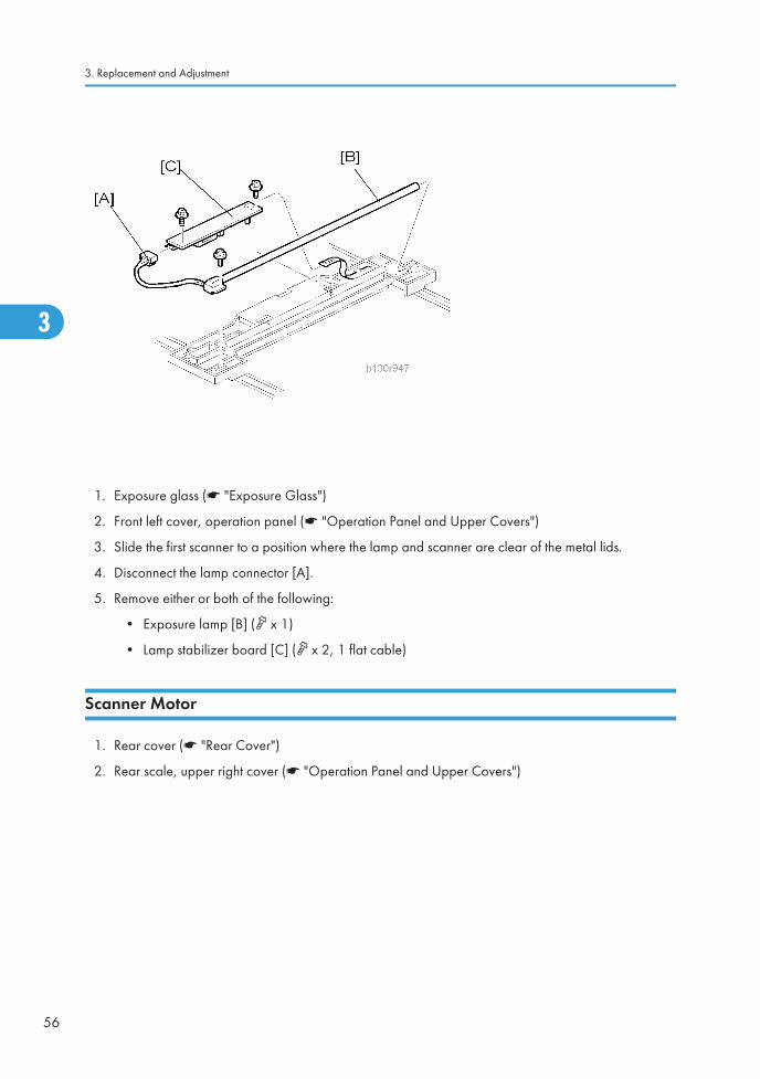
1. Exposure glass (* "Exposure Glass")
2. Front left cover, operation panel (* "Operation Panel and Upper Covers")
3. Slide the first scanner to a position where the lamp and scanner are clear of the metal lids.
4. Disconnect the lamp connector [A].
5. Remove either or both of the following:
• Exposure lamp [B] ( x 1)
• Lamp stabilizer board [C] ( x 2, 1 flat cable)
Scanner Motor
1. Rear cover (* "Rear Cover")
2. Rear scale, upper right cover (* "Operation Panel and Upper Covers")
3. Replacement and Adjustment
56
3

3. Remove the right platen stay holder [A] ( x 3).
4. Scanner motor [B] ( × 3, 1 spring, 3 screw holders, × 1)
Reinstalling
When reinstalling, fasten the screws loosely, set the spring in place, and tighten up the screws.
Scanner Unit
57
3

Scanner HP Sensor
1. Rear cover (* "Rear Cover")
2. Front left cover (* "Operation Panel and Upper Covers")
3. Scale plate (* "Scale Plate")
4. Scanner HP sensor [A] ( × 1, hook)
• Move the first scanner from the home position if you have difficulty removing the sensor.
Scanner alignment adjustment
1. Rear cover (* "Rear Cover")
2. Rear scale, upper right cover, front left cover, operation panel (* "Operation Panel and UpperCovers")
3. Exposure glass (* ”Exposure Glass").
4. Loosen the 2 screws holding the 1st and 2nd scanner belts in place.
3. Replacement and Adjustment
58
3

5. Slide the 1st and 2nd scanners so that all four of the following are roughly aligned on both the frontand back sides:
• The hole on the copier's lid
• The hole on the 1st scanner
• The corner right hole on the 2nd scanner
• The hole at the base of the scanner
6. Insert the two optics adjustment tools [A], and adjust the scanners as necessary so that the tools gothrough all four holes.
7. Tighten the two screws that you loosened at step 2 above, so that the belts are firmly clamped intoplace.
8. Remove the adjustment tools.
Scanner Unit
59
3

Fusing
Fusing Unit
• Before handling the fusing unit, make sure that the unit is cool enough. The fusing unit can be very hot.
1. Copy tray (* "Copy Tray")
2. Open the right door.
3. Connector cover [A] ( x 1)
• When reinstalling, attach the ground wire.
4. Fusing unit [B] ( x 2, x 4)
3. Replacement and Adjustment
60
3

Exit Sensor
1. Fusing unit (* "Fusing Unit")
2. Exit sensor [A] ( × 1)
Hot Roller Stripper Pawls
• Take care not to damage the hot roller stripper pawls and the tension springs.
Fusing
61
3

1. Fusing unit (* "Fusing Unit")
2. Separate the fusing unit into two sections: the hot roller section [A] and the pressure roller section [B]( x 2).After removing the screws, lower the pressure roller section about halfway and then slide it towardthe front side to detach it.
3. Support rollers [C]
4. Hot roller stripper pawls [D]
• Remove the spacer [E] if you are removing the hot roller assembly (* "Hot Roller & FusingLamp").
Hot Roller & Fusing Lamp
• Do not touch the fusing lamp and rollers with your bare hands.
3. Replacement and Adjustment
62
3

1. Hot roller stripper pawls and spacers (* " Hot Roller Stripper Pawls")
2. Hot roller assembly [A] ( x 2)
3. Fusing lamp [B]
• When reassembling, check that the direction of the fusing lamp is correct.
4. Hot roller [C] (2 C-rings, 1 spacer, 1 gear, 2 bushings, 1 cover [D])
Reassembling
Be sure that:
• The fusing lamp is positioned correctly.
• The fusing lamp does not touch the internal part of the hot roller.
Fusing
63
3

Thermoswitches and Thermistor
1. Hot roller assembly (* "Hot Roller & Fusing Lamp")
2. Thermoswitches ( x 2 for each)
3. Thermistor ( x 1)
Reassembling
Make sure of the following:
• That the thermistor is in contact with the hot roller.
• That the hot roller turns smoothly.
• Do not recycle a thermoswitch that is already opened. Safety is not guaranteed if you do this.
3. Replacement and Adjustment
64
3

Pressure Roller
1. Separate the fusing unit into two sections (* "Hot Roller Stripper Pawls").
2. Fusing entrance guide [A]
3. Two springs [B][C]
4. Two pressure arms [D][E]
5. Bushing [F]
6. Pressure roller [G]
Fusing
65
3

Checking the NIP band
You can check the nip band to see if the fusing unit is in a good condition–especially, if the hot roller andpressure roller are correctly installed.
1. Activate the SP mode.
2. Select SP1-109-001.
3. Specify "1."
4. Press the OK key.
5. Press the key. The copy mode is activated.
6. Place an OHP sheet on the by-pass tray.
7. Press the key. The copier feeds the OHP sheet, and stops it between the hot roller and the pressureroller for about 20 seconds.
8. Wait until the OHP sheet is output.
9. Press the key.
10. Make sure SP1-109-001 is selected.
11. Specify "0".
12. Press the OK key.
13. Quit the SP mode.
You see an opaque stripe on the OHP sheet. This is the trace of the nip band. The normal nip band issymmetrical on the OHP sheet. Both ends are slightly thicker than the center.
• There are no specifications or standards for the nip band of this copier.
3. Replacement and Adjustment
66
3

PCU and Quenching LampWhen handling the photo conductor unit (PCU), use caution:
• Do not touch the OPC drum with your bare hands. When the OPC drum is unclean, clean it with drycloth, or clean it with wet cotton and wipe it with dry cloth.
• Do not use alcohol any other chemicals to clean the OPC drum. These substances damage the OPC-drum surface.
• Keep PCUs in a cool, dry place.
• Do not expose the OPC to any corrosive gas such as ammonia.
• Do not shake a used PCU. Remaining toner and developer may spill out.
• Dispose of used PCUs in accordance with local regulations.
PCU
1. Open the right door.
• The PCU may become stuck if you try to remove it while the front door is closed.
2. Open the front door.
3. Remove the toner bottle holder.
• Clean all spilled toner off the toner bottle area and the inside of the front door.
4. Pull out the PCU [A] ( x 1).
5. When having installed a new PCU, remove the Styrofoam and tags (* "Installation Procedure" in thesection "Installation").
Initialization
PCU and Quenching Lamp
67
3

After you turn on the main power switch, the copier automatically initializes the new PCU. When the copieris executing initialization, it is important that you:
• Do not turn off the main power switch.
• Do not open or remove exterior covers.
Quenching Lamp
1. PCU (* "PCU")
2. Quenching lamp [A] ( x 1)
3. Replacement and Adjustment
68
3

Exhaust Fan and Main Motor
Exhaust Fan
1. Rear cover (* "Rear Cover")
2. Exhaust fan [A] ( x 2, x 1)
Reassembling
Make sure that the arrow [B] on the frame points to the rear side. The arrow indicates the direction ofairflow.
Exhaust Fan and Main Motor
69
3

Main Motor
1. Rear cover (* "Rear Cover")
2. High-voltage power supply board (* "High-Voltage Power Supply Board")
3. Ground plate [A] ( x 1)
4. Main motor with the gear cover [B] ( x 1, x 7, x 2, 2 bushings)
5. All gears [C]
6. Main motor [D] ( x 4)
Reassembling
Attach the main motor before attaching the gears.
3. Replacement and Adjustment
70
3

Paper Feed
Paper Feed Roller and Friction Pad
When handling the paper tray or the paper feed roller, use caution:
• Do not touch the surface of paper feed rollers.
• To avoid paper jams, correctly set the side and end fences in the paper tray.
1. Paper tray
2. Shaft [A] ( x 1)
3. Remove either or both of the following:
• Paper feed roller [B]
• Friction pad [C]
Paper Feed
71
3

Paper End Sensor
1. Paper tray
2. Open the right door.
3. PCU (* ”PCU")
4. Paper end sensor [A] ( x 1)
Registration Sensor
1. Paper tray
2. Open the right door.
3. Open the paper guide [A].
• Remove the paper guide (Clip x 1) if you have difficulty removing the registration sensor.
3. Replacement and Adjustment
72
3

4. Registration sensor feeler [B]
5. Registration sensor [C] ( x 1)
• Disconnect the connector (CN127 [D]) if you have difficulty removing the registration sensor.
Bypass Paper End Sensor
1. Right door (* "Right Door")
2. Sensor compartment [A]
3. Bypass paper end sensor [B] ( x 1)
Paper Feed
73
3

Bypass Feed Roller
1. Right door (* "Right Door")
2. Turn the feed roller housing upside down [A] ( x 2).
3. Feed roller shaft [B] (2 snap pawls [C], 1 spacer [D])
4. Bypass feed roller [E]
3. Replacement and Adjustment
74
3

Bypass Feed Clutch and Friction Pad
1. Rear cover (* "Rear Cover")
2. Right door (* "Right Door")
3. Disconnect the bypass feed clutch connector [A] (CN93).
4. Bypass feed roller housing [B] ( x 2)
5. Bypass feed clutch [C] ( x 1)
6. Bypass friction pad [D]
Paper Feed
75
3

Paper Feed and Registration Clutches
1. Paper tray
2. High-voltage power supply board (* "High-Voltage Power Supply Board")
3. Ground plate [A] ( x 1)
4. Gear cover [B] ( x 1, x 7, x 2, 2 bushings)
• Do not remove the main motor from the gear cover.
3. Replacement and Adjustment
76
3

5. Ground plate [C] ( x 1)
6. Slowly push the clutch holder [D] and remove the registration clutch [E] ( x 1, x 1).
7. Paper feed clutch [F]
Paper Feed
77
3

Image Transfer
Transfer Roller
• Do not touch the transfer roller with your bare hands.
• Do not scratch the transfer roller. The transfer roller is easily damaged.
1. Right door (* "Right Door")
2. Raise the levers [A][B] at the ends of the image transfer roller.
3. Release the image transfer roller [C].
Reassembling
Make sure that the springs [D] are in the original positions.
3. Replacement and Adjustment
78
3

ID Sensor and Duplex Roller
1. Right door (*"Right Door")
2. Lower guide [A]
3. Idle roller holders [B][C]
4. Idle roller [D]
5. Roller guide [E]
6. Transfer unit [F]
7. One-way gear [G] ( x 1)
8. Duplex roller [H] ( x 1, 3 bushings)
Image Transfer
79
3

9. ID sensor ( x 1)
Discharge plate
1. Right door (*"Right Door")
2. Discharge plate [A].
3. Replacement and Adjustment
80
3

BICU and Controller BoardNote that the basic model (B262/B292) and GDI models (B280/B293) have different components. Thetable lists the components and necessary maintenance work.
Model
BICUNVRAM
ControllerBox
ControllerNVRAM
Maintenance Work
Ba-sic
Installed None NoneSave the data from the NVRAM to a memory card be-fore replacing the NVRAM.
GDI Installed Installed Installed
• Save the data from the NVRAM to a memory cardbefore replacing the NVRAM on the BICU.
• Replace the installed NVRAM from the old con-troller board to the new controller board.
BICU
• Before replacing the NVRAM, be sure to save the NVRAM data.
• Saving from the BICU NVRAM to a memory card (* "NVRAM Data Upload/Download(SP5-824/825)" in the section "Service Tables")
1. Rear cover (* "Rear Cover")
BICU and Controller Board
81
3

2. Bracket at the left-rear frame (basic models [B262/B292]: x 2) or controller box [A] (GDI models[B280/B293]: x 5)
3. Ground plate [B] ( x 2)
4. BICU [C] (all , 2 flat cables, x 6)
• When replacing the BICU, remove the NVRAM [D] from the board. Install the NVRAM to thenew board.
5. After replacing the NVRAM, copy the saved data to the NVRAM.
• From a memory card to the NVRAM (* "NVRAM Data Upload/Download (SP5-824/825)"in the section "Service Tables")
Controller Board (B280/B293 models only)
1. Rear cover (* "Rear Cover")
3. Replacement and Adjustment
82
3

2. Controller box cover [A] ( x 12)
3. Controller board [B] ( x 5)
• When replacing the controller board, remove the NVRAM [D] from the board. Install the NVRAMto the new board.
When replacing the NVRAM on the controller board
When you replace the NVRAM [C], make sure that the NVRAM is correctly installed.
BICU and Controller Board
83
3

The mark [D] on the NVRAM is directed to the right side (seem from the front).
3. Replacement and Adjustment
84
3

Other Replacements
Duplex Motor
1. Rear cover (* "Rear Cover")
2. Duplex motor [A] ( x 1, x 2)
Other Replacements
85
3

High-Voltage Power Supply Board
1. Rear cover (* "Rear Cover")
2. High-voltage power supply board [A] (all , x 4)
• Remove the insulating sheet [B] if you are going to remove the contact-release solenoid (*"Contact-Release Solenoid") or the gear cover (* "Paper Feed and Registration Clutches").
3. Replacement and Adjustment
86
3

PSU
1. Open the front door.
2. Copy tray (* "Copy Tray")
3. PSU assembly [A] ( x 4, x 8)
4. PSU [B] ( x 1, x 6)
• The North America models do not have the connector.
Other Replacements
87
3

Contact-Release Solenoid
1. Rear cover (* "Rear Cover")
2. High-voltage power supply board (* "High-Voltage Power Supply Board")
3. Contact-release solenoid (1 spring, x 1)
Toner Supply Clutch
1. Toner bottle holder
3. Replacement and Adjustment
88
3

2. Copy tray (* "Copy Tray")
3. Rear cover (* "Rear Cover")
4. Disconnect the connector on C19 on the BICU.
5. Push the clutch coupler [A] to the rear side, and remove the clip ring [B] from the back of the copier.
6. Coupler and spring [C]
7. Lift the toner supply clutch [D] and remove it.
• When removing, note how the wire goes through a clamp, and also note where it passes throughthe rear of the machine.
Other Replacements
89
3

Laser Unit
• Turn off the main power switch and unplug the copier before starting replacement. The laser beamcan damage your eyes severely.
• Do not touch the screws on the LD board on the LD unit. Do not try to adjust any part of the LD unit.The LD unit is precision adjusted before shipment.
• Do not touch the polygon mirror, shield glass, or lenses with your bare hands.
Location of the Caution Decal
Laser Unit
1. PSU assembly (* "PSU")
2. Toner bottle holder
3. Replacement and Adjustment
90
3

3. Laser unit [A] ( x 3, x 2)
Reassembling
Make sure that the cable [B] passes under the unit.
LD Unit and Polygon Mirror Motor
1. Laser unit (* "Laser Unit")
2. Laser unit cover [A] ( x 2, 1 grounding plate)
3. LD unit [B] ( x 2)
4. Polygon mirror motor [C] ( x 4)
Reassembling
Check that the polygon mirror and toroidal lens are clean. Dust or other foreign substances may interferewith the operation of the LD unit.
Laser Unit
91
3

Adjusting Copy Image AreaAdjust the copy image area under any of the following conditions:
1. After clearing engine data (SP5-801-002 or SP5-998-001).
2. After replacing any of the following components:
• First scanner or second scanner
• Lens block
• Scanner motor
• Polygon mirror motor
• Paper tray
Printing
Make sure that the paper is correctly loaded in each paper tray before starting the adjustment proceduresin this section.
Adjusting Registration
Use the Trimming Area Pattern (SP5-902-001 > 10) for this adjustment.
1. Print out the test pattern with the paper fed from the regular paper tray.
2. Print out the test pattern with the paper fed from the by-pass tray.
3. Print out the test pattern by selecting duplex printing.
4. Measure the distance between the leading edge of the image area and the leading edge of the paper[A].
• The diagram shows the paper on the copy tray. Note that the paper is output with the face down.
3. Replacement and Adjustment
92
3
SP Specification
SP1-001-001 (All Trays) 0 ± 2 mm
SP1-001-002 (By-pass) 0 ± 2 mm
SP1-001-003 (Duplex) 0 ± 4 mm
5. Adjust the leading edge registration (SP1-001).
6. Measure the distance between the side edge of the image area and the side edge of the paper [B].
SP Specification
SP1-002-001 (1st tray) 0 ± 2 mm
SP1-002-002 (2nd tray) 0 ± 2 mm
SP1-002-005 (By-pass) 0 ± 4 mm
SP1-002-006 (Duplex) 0 ± 4 mm
7. Adjust the side-to-side registration (SP1-002).
8. Specify "0" (zero) in SP5-902-001 after finishing the adjustment procedure.
Adjusting Blank Margin
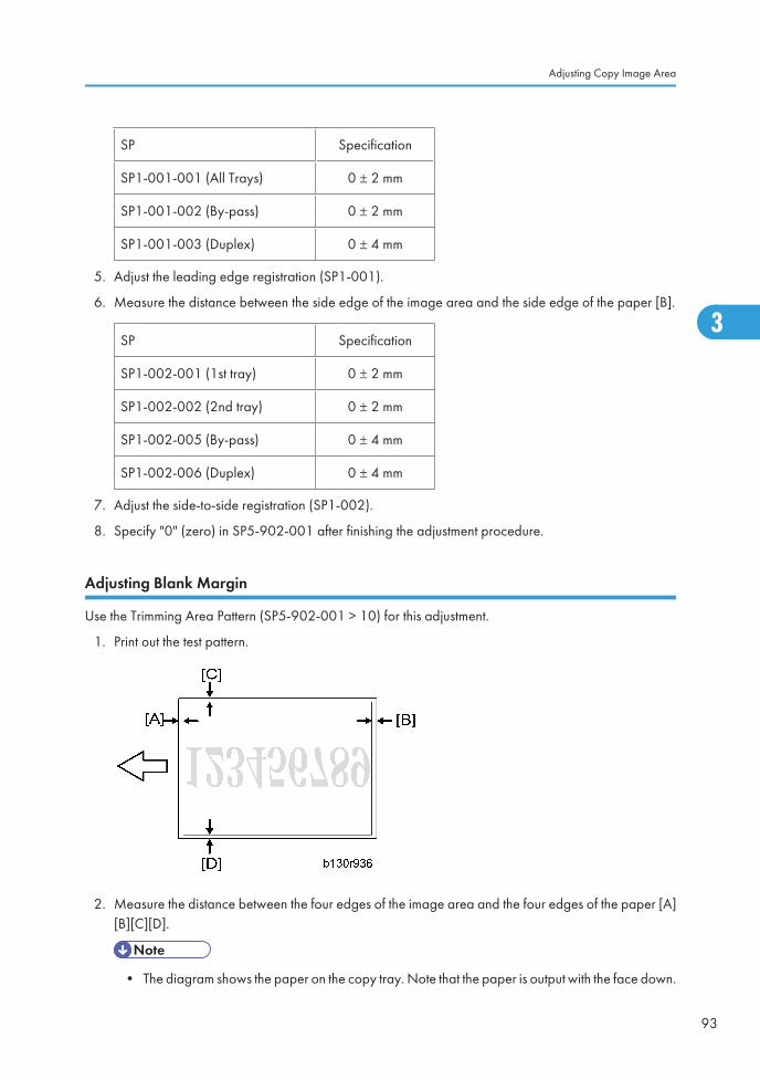
Use the Trimming Area Pattern (SP5-902-001 > 10) for this adjustment.
1. Print out the test pattern.
2. Measure the distance between the four edges of the image area and the four edges of the paper [A][B][C][D].
• The diagram shows the paper on the copy tray. Note that the paper is output with the face down.
Adjusting Copy Image Area
93
3

3. Adjust the blank margin (SP2-101).
SP Specification
SP2-101-001 (Leading Edge) [A] 2 ± 1.5 mm
SP2-101-002 (Trailing Edge) [B] 2 +2.5/-1.5 mm
SP2-101-003 (Left Side) [C] 2 ± 1.5 mm
SP2-101-004 (Right Side) [D] 2 +2.5/-1.5 mm
• The "Left Side" and "Right Side" comes to your left-hand side and right-hand side respectivelywhen you view the copied image with the leading edge upwards.
4. Specify "0" (zero) in SP5-902-001 after finishing the adjustment procedure.
Adjusting Main-Scan Magnification
Use the Grid Pattern (Single Dot) (SP5-902-001 > 5) for this adjustment.
SP Specification
SP2-998-001 (Main Mag-print) 100 ± 1%
1. Print out the test pattern.
2. Measure the sides of squares. Each side should be 2.7-mm long.)
3. Adjust the main-scan magnification (SP2-998-001: Main Mag-print).
4. Specify "0" (zero) in SP5-902-001 after finishing the adjustment procedure.
Scanning
• Before adjusting scanning, adjust printing (* "Printing" in this section).
• To adjust scanning, use the A4 test chart.
Adjusting Registration
1. Place the test chart on the exposure glass. Make sure that the test chart is aligned with the rear andleft scales on the exposure glass.
3. Replacement and Adjustment
94
3

2. Make a copy.
3. Measure the distance between the leading edge of the image area and the leading edge of the paper[A].
• The diagram shows the paper on the copy tray. Note that the paper is output with the face down.
4. Adjust the leading-edge scan registration. (SP4-010-001).
SP Specification
SP4-010-001 (LE Scan Regist) 0 ± 2 mm
5. Measure the distance between the side edge of the image area and the side edge of the paper [B].
6. Adjust the side-to-side registration (SP4-011-001).
SP Specification
SP4-011-001 (S-to-S Scan Regist) 0 ± 2 mm
Adjusting Copy Image Area
95
3

Adjusting Magnification
1. Place the test chart on the exposure glass. Make sure the test chart is aligned with the rear and leftscales on the exposure glass.
2. Make a copy.
3. Compare the copy with the original.
4. Adjust the main-scan and sub-scan magnifications. The original image [A] is magnified in the main-scan direction [B] or in the sub-scan direction [C] when you specify a larger value.
• The diagrams show the paper on the copy tray. Note that the paper is output with the face down.
SP Specification
SP4-009-001 (Main Scan Mag) ± 1.0%
SP4-008-001 (Sub Scan Mag) ± 1.0%
Scan Auto Adjustment
This procedure adjusts the standard white density level. Adjust the standard white density after any of thefollowing maintenance work:
• Replacing the standard white plate
• Replacing the BICU
3. Replacement and Adjustment
96
3

• Replacing the lens block
• Executing the memory clear (SP5-801-002 [basic model], SP5-998-001 [other models]).
1. Place 10 sheets of new A4 paper on the exposure glass.
2. Close the platen cover.
3. Activate the SP mode.
4. Select Copy SP4-428.
5. Specify "1" and press the OK key. The copier automatically adjusts the standard white density.
DF Image Adjustment
• Perform the adjustment procedure in this section only when the ARDF is installed on the copier.
1. Make a temporary test chart as shown in the above diagram. Use the A4/8.5 x 11" paper to makeit.
2. Place the temporary test chart on the ARDF.
3. Make a copy.
4. Measure the distance between the side edge of the image area and the side edge of the paper [A].
Adjusting Copy Image Area
97
3

(The diagram shows the paper on the copy tray. Note that the paper is output with the face down.)
5. Adjust the side-to-side registration (S to S/Front Regist: SP6-006-001, S to S/Rear Regist:SP6-006-004). The image area moves to the rear side of the copier when you specify a larger value.
6. Measure the distance between the leading of the image area and the leading edge of the paper [B].
7. Adjust the leading edge registration (Leading Regist: SP6-006-002). The image area moves to theright side of the copier when you specify a larger value.
8. Measure the distance between the trailing edge of the image area and the trailing edge of the paper[C].
9. Adjust the erased area on the trailing edge (Trailing Erase: SP6-006-003).
10. Compare the copy with the original.
11. Adjust the sub-scan magnification (SP6-006-005). The specification is ±1.0%.
3. Replacement and Adjustment
98
3

4. Troubleshooting
Service Call Conditions
Summary
There are four levels of service call conditions.
Level Definition Reset Procedure
ATo prevent possible damage, the machine does notoperate until the service representative resets the SCcode.
Activate the SP mode, and turn themain power switch off and on.
BTurning the main power stitch off and on resets the SCcode if the error is caused by incorrect sensor detection.
Turn the main power switch off andon.
CThe machine operates as usual excluding the unit re-lated to the service call.
Turn the main power switch off andon.
DThe SC history is updated. The machine operates asusual.
No SC code is displayed. Only theSC history is updated.
• If a problem involves circuit boards, see if you can solve the problem by disconnecting and recon-necting all connectors before deciding to replace a circuit board.
• If a problem involves a motor lock, check the mechanical load before deciding to replace a motoror sensor.
• If working on a fax-equipped machine, switching power off and on may cause loss of data stored inthe memory.
SC Code Descriptions
No.Definition
Symptom Possible Cause
101 B
Exposure Lamp Error
The scanner has scanned the white plate,but cannot detect the white level.
• Defective exposure lamp
• Defective exposure lamp stabilizer
99
4

No.Definition
Symptom Possible Cause
• Defective exposure lamp connector
• Unclean scanner mirror
• Scanner mirror out of position
• Defective SBU board
• Defective SBU connector
• Lens block out of position
• Incorrect position or width of whiteplate scanning (* SP4-015)
120 B
Scanner home position error 1
The scanner home position sensor does notdetect the scanner leaving the home posi-tion.
• Defective scanner home position sen-sor
• Defective scanner drive motor
• Defective scanner home position sen-sor connector
• Defective scanner drive motor con-nector
• Defective BICU board
121 B
Scanner home position error 2
The scanner home position sensor does notdetect the scanner coming back to thehome position.
• Defective scanner home position sen-sor
• Defective scanner drive motor
• Defective scanner home position sen-sor connector
• Defective scanner drive motor con-nector
• Defective BICU board
141 B
SBU black level correction error
• The automatic SBU adjustment hasfailed to correct the black level threetimes at the pre-offset adjustment.
• Defective SBU board
4. Troubleshooting
100
4

No.Definition
Symptom Possible Cause
• The automatic SBU adjustment hasfailed to correct the black level tentimes at the PGA adjustment.
• The automatic SBU adjustment hasfailed to correct the black level tentimes at the offset adjustment.
142 B
SBU white/black level correction error
The automatic SBU adjustment has failedto correct the white level ten times at thePGA adjustment.
• Defective exposure lamp
• Unclean white plate
• Incorrect position or width of whiteplate scanning (* SP4-015)
• Defective SBU board
144 B
Communication Error between BICU and SBU
The BICU cannot correctly establish com-munication with the SBU.
• Loose connection of the flat cable be-tween the BICU and the SBU
• Defective flat cable between the BICUand the SBU
• Defective BICU
• Defective SBU
145 D
Automatic SBU adjustment error
The white levels of the white plate and thewhite paper are extraordinarily differentduring the Scan Auto Adjustment (*SP4-428-001).
• Defective exposure lamp
• Unclean white plate
• Incorrect position or width of whiteplate scanning (* SP4-015)
• Defective BICU board
• Defective SBU board
193 B
Image transfer error
Scanned images are not transferred to thecontroller memory within one minute.
• Defective BICU board
• Defective controller board
198 B Memory address error
Service Call Conditions
101
4

No.Definition
Symptom Possible Cause
The BICU does not receive the memory ad-dress report from the controller within oneminute.
• Inconsistency between the BICU firm-ware and the controller firmware
• Defective BICU
• Defective controller
302 B
Charge roller current leak
The polling module detects a current leakof the charge roller.
• Defective charge roller
• Defective high voltage supply board
• Loose connection of the PCU
320 B
Polygonal mirror motor error
The polygon mirror motor does not reachthe operating speed within 10 seconds.Or, the polygon mirror motor remains outof the operating speed for 0.2 second afterreaching the operating speed.
• Defective polygon mirror motor
• Loose connection between the polyg-onal mirror motor and the BICU
• Defective cable between the BICUand the polygon mirror motor
• Defective BICU
321 B
No laser writing signal (F-GATE) error
The poling module does not detect the laserwriting signal (F-GATE) asserting after thelaser crosses 5 mm from the start point onthe drum surface.
• Defective BICU
• Loose connection on the fax controlleror the printer controller
• Defective fax controller or printer con-troller
322 B
Laser synchronization error
The main scan synchronization detectordoes not detect the laser signal for 0.5 sec-ond.
• Toner bottle not installed
• Loose connection between the LD unitand the BICU
• Defective cable between the BICUand LD unit
• LD unit out of position
• Defective LD unit
• Defective BICU
4. Troubleshooting
102
4

No.Definition
Symptom Possible Cause
390 B
TD sensor error
The BICU detects the TD sensor outputtingextraordinary voltage (less than 0.2 V ormore than 4.0 V) 10 times consecutively.
• Defective TD sensor
• Loose connection of the PCU
391 B
Development bias leak
The polling module detects a current leakof the development bias.
• Loose connection of the PCU
• Defective high voltage supply board
392 B
Developer initialization error
The ID sensor does not detect a correctpattern during developer initialization (*2-214-001).
• Defective ID sensor
• Insufficient developer
• Defective drum operation
• Defective development roller opera-tion
• Loose connection of the PCU
• Insufficient voltage for the charge roll-er
401 B
Transfer roller leak error (positive electrode)
The feedback voltage of the transfer rolleris insufficient.
• Defective high voltage supply board
• Loose connection of the PCU
• Incorrect installation of the transferunit or the separation unit
• Defective transfer roller
402 B
Transfer roller leak error (negative electrode)
The feedback voltage of the transfer rolleris insufficient.
• Defective high voltage supply board
• Loose connection of the PCU
• Incorrect installation of the transferunit or the separation unit
• Defective transfer roller
500 B Main motor error
Service Call Conditions
103
4

No.Definition
Symptom Possible Cause
The main motor does not reach its opera-tion speed within 0.7 second. Or, the mainmotor remains out of its operation speed for0.7 second after reaching the operationspeed.
• Overload
• Defective main motor
541 A
Fusing thermistor open error
The fusing temperature remains lower thanthe specified temperature by 20 degreesCelsius.
• Defective thermistor
• Incorrect installation of the thermistor
• Defective power supply unit
• Loose connectors
542 A
Fusing temperature warm-up error
The fusing temperature rises 7 degrees orless in two seconds; and this continues 5times consecutively. Or, the fusing temper-ature is not detected within 25 or 35 sec-onds.
• Defective thermistor
• Incorrect installation of the thermistor
• Defective fusing lamp
• Defective power supply unit
543 A
Fusing overheat error 1
The fusing temperature detected by thethermistor is 230°C or higher for one sec-ond.
• Defective thermistor
• Defective power supply unit
544 A
Fusing overheat error 2
The fusing temperature detected by themonitor circuit is 250°C or higher for onesecond.
• Defective thermistor
• Defective power supply unit
545 A
Fusing lamp overheat error
After the fusing temperature reaches thetarget, the fusing lamp remains on for 12seconds.
• Defective thermistor
• Incorrect installation of the thermistor
• Defective power supply unit
546 A Unstable fusing temperature
4. Troubleshooting
104
4
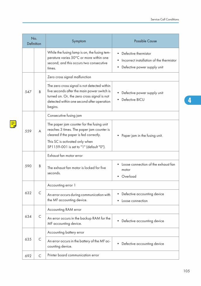
No.Definition
Symptom Possible Cause
While the fusing lamp is on, the fusing tem-perature varies 50°C or more within onesecond; and this occurs two consecutivetimes.
• Defective thermistor
• Incorrect installation of the thermistor
• Defective power supply unit
547 B
Zero cross signal malfunction
The zero cross signal is not detected withinfive seconds after the main power switch isturned on. Or, the zero cross signal is notdetected within one second after operationbegins.
• Defective power supply unit
• Defective BICU
559 A
Consecutive fusing jam
The paper jam counter for the fusing unitreaches 3 times. The paper jam counter iscleared if the paper is fed correctly.
This SC is activated only whenSP1159-001 is set to "1" (default "0").
• Paper jam in the fusing unit.
590 B
Exhaust fan motor error
The exhaust fan motor is locked for fiveseconds.
• Loose connection of the exhaust fanmotor
• Overload
632 C
Accounting error 1
An error occurs during communication withthe MF accounting device.
• Defective accounting device
• Loose connection
634 C
Accounting RAM error
An error occurs in the backup RAM for theMF accounting device.
• Defective accounting device
635 C
Accounting battery error
An error occurs in the battery of the MF ac-counting device.
• Defective accounting device
692 C Printer board communication error
Service Call Conditions
105
4

No.Definition
Symptom Possible Cause
• BICU does not get a signal from theprinter board for 1.5 seconds ormore.
• BICU gets a break-signal after com-pleting the communication with theprinter board and does not get a sig-nal from the printer board for 10 sec-onds or more.
• Defective communication betweenBICU and printer board
694 C
Scanner board communication error
• BICU does not get a signal from thescanner board for 1.5 seconds ormore.
• BICU gets a break-signal after com-pleting the communication with thescanner board and does not get asignal from the scanner board for 10seconds or more.
• Defective communication betweenBICU and scanner board
760 B
ADF gate error 1
The ADF sends the FGATE signal before itis requested to scan originals.
• Defective ADF board
• Defective input/output board
• Loose connection
761 B
ADF gate abnormal 2
The ADF does not send the FGATE signalwithin 30 seconds after the ADF starts scan-ning.
• Defective ADF connector
• Defective SBU board
762 B
ADF gate abnormal 3
The ADF continues to send the FGATE sig-nal for more than 60 seconds after the ADFstarts scanning.
• Defective ADF connector
• Defective SBU board
901 B
Mechanical total counter error
The polling module does not detect the me-chanical total counter.
• Defective mechanical total counter
4. Troubleshooting
106
4

No.Definition
Symptom Possible Cause
• Defective BICU
• Loose connection
903 B
Engine total counter error
The checksum of the total counter is notcorrect.
• Defective NVRAM on the BICU
928 B
Memory error
An error occurs during the memory checkconducted when the main power switch isturned on or when the copier is recoveringfrom the energy saver mode.
• Defective memory
• Defective BICU
• Loose connection between the BICUand the memory
929 B
IMAC hardware error
A memory control job is not completedwithin a certain period.
• Defective IMAC
• Defective BICU
• Loose connection
981 B
NVRAM error
An error occurs during engine NVRAMcheck.
• Defective NVRAM
• Loose connection between the BICUand the NVRAM
• Incorrect installation of the NVRAM
• Defective BICU
982 B
Localization error
The localization information in the nonvo-latile ROM and in the NVRAM is different(* SP5-807-001).
• Localization setting not specified (Themain power switch is turned on for thefirst time after the NVRAM is re-placed.)
• Incorrect localization setting
• Defective NVRAM
Service Call Conditions
107
4

Electrical Component Troubleshooting
Sensor/Switch Open Errors
Sensor Connector Message Remarks
Registration SensorCN127
Paper jam -SN
Paper End SensorCN129
Load paper -SN
Bypass Paper EndSensor
CN130(None)
The machine cannot detect paper onthe bypass tray.SN
Paper Path SensorCN128
Paper jam -SN
Exit SensorCN128
Paper jam -SN
Image Density (ID)Sensor
CN132(None) Print quality may become worse.
SN
Toner Density (TD)Sensor
CN123 SC901The connector is shared with the me-chanical total counter.
PCU Reset PCU correctly -
Scanner HP SensorCN126 SC120 -
SN SC120 -
Platen Cover Sensor
CN126 SC120 -
SN (None)The copier does not warm up whenyou open the platen cover.
DF Guide Open Sen-sor
DF CN103 Paper jam -
SN (None) -
4. Troubleshooting
108
4

Sensor Connector Message Remarks
DF Original Set Sen-sor
DF CN103 Paper jam -
Sensor (None) Originals are not detected.
DF Registration Sen-sor
DF CN103Paper jam
-
SN Originals are correctly transported.
Inverter SensorDF CN103 Paper jam -
SN (None) -
Exit SensorDF CN103
Paper jam-
SN -
Front Door Switch
CN114 Right door open -
SW Front/Right door openThe message depends on which cir-cuit is open (white → front; blue →right).
Right Door SwitchCN114 Right door open -
SW Right door open -
CNxxx: The connector on the BICU board.
DF CNxxx: The connector on the DF connection board.
SN: The connector on the sensor.
SW: The connector on the switch.
PCU: The connector on the PCU.
Blown Fuse Conditions
All of these fuses are on the power supply unit.
FuseRating
At main switch ON120 V 220 – 240 V
FU1 15A/125V 8A/250 V No response
FU2 5A/125V 2.5A/250V No response
Electrical Component Troubleshooting
109
4

BICU LED Display
Number Function
LED2 LED2 blinks in normal operation.
4. Troubleshooting
110
4

5. Service Tables
Service Program
• Do not let the user access the SP mode or the SSP mode. Only service representatives are allowed toaccess these modes. The machine operation is NOT guaranteed after any person other than servicerepresentatives accesses the SP mode or the SSP mode.
Using SP and SSP Modes
The following two modes are available:
• SP Mode (Service Program Mode): The SP Mode includes the programs that are necessary for stand-ard maintenance work.
• SSP Mode (Special SP Mode): The SSP Mode includes SP-Mode programs and some special pro-grams. You need some extra knowledge to use these special programs. For details, consult yoursupervisor.
Starting SP Mode
1. Type the keys as follows: →→→
2. Press the key and hold it down until the SP-mode menu is displayed (about 3 seconds).
111
5

Starting SSP Mode
The SSP mode is not available on the basic model (the machine without the controller box).
1. Type the keys as follows: →→→
2. Press the key and hold it down until the SP-mode menu is displayed (about 3 seconds).
3. Press the key and hold it down.
4. While holding down the key, press the key (on the numeric keypad).
5. While holding down the key, press the “OK” key.
Selecting Programs
• When a blinking underscore (or several blinking underscores) is displayed, you can type a numberfrom the numeric keypad [D].
• When the sign “/OK” [A] is displayed upper right corner, you can scroll through the menu bypressing the left-arrow key [B] or the right-arrow key [C]. To select program, press the OK key [F].
Specifying Values
1. After locating a program, press the OK key. A blinking underscore (or several blinking underscores)indicates which value you can change. The value in parentheses is the default value of the menu.
2. Type a necessary value from the numeric keypad. To switch between positive (plus) and negative(minus) values, press the key.
3. To validate the value, press the OK key. To cancel the value, press the escape key [E].
Activating Copy Mode
You can activate the copy mode while the SP mode is running. When you do so, the copier outputs imagesor patterns that help you adjust the SP setting.
1. Press the key. The copy mode is activated.
2. Specify copy settings and press the key.
3. To return to the SP mode, press the key.
1. You cannot end the SP mode while the copy mode is activated.
Quitting Programs/Ending (S) SP Mode
Press the key or the escape key to quit the program. You can end the SP mode by pressing one ofthese keys several times.
5. Service Tables
112
5

Copier Service Program Mode Tables
Conventions used in the tables:
• Asterisk (*): The settings are saved in the NVRAM. Most of them return to the default values when youexecute SP5-801-002.
• DFU: The program is for design/factory use only. Do not change the settings.
• Brackets ([ ]): The brackets enclose the setting rage, default value, and minimum step with unit ([Min-imum to Maximum / Default / Step]).
SP1-XXX (Feed)
1001* Leading Edge Registration [–9.0 to 9.0 / 0.0 / 0.1 mm/step]
1001 1 All TraysAdjusts the leading-edge registration (* "AdjustingCopy Image Area" in the section "Replacement andAdjustment").
1001 2 By-pass
1001 3 Duplex
1002* side-to-side Registration [–9.0 to 9.0 / 0.0 / 0.1 mm/step]
1002 1 1st Tray Adjusts the side-to-side registration (* "Adjusting CopyImage Area" in the section "Replacement and Adjust-ment"). SP1-002-001 is applied to all trays.SP1-002-002 and 005 adjusts the difference fromSP1-002-001.
1002 2 2nd Tray
1002 5 By-pass
1002 6 DuplexAdjusts the side-to-side registration of the 2nd side induplex copying. The 1st side is adjusted bySP1-002-001 through 005.
1003* Paper Feed TimingAdjusts the amount of paper buckle on the registrationroller.
1003 1 1st tray [0 to 10 / 5 / 1 mm/step]
1003 3 Paper bank [0 to 10 / 5 / 1 mm/step]
1003 4 By-pass feed [0 to 10 / 5 / 1 mm/step]
1003 5 Duplex [0 to 20 / 5 / 1 mm/step]
Service Program
113
5

1103* Fusing Idling [0 = No / 1 = Yes]
1103 1
Enables or disables the contact-release control. The following table lists the results.
Setting 0 = No 1 = Yes
C-R control Works Does not work
Idling time Shorter Longer
Fusing quality Lower Higher
1105*
Fusing Temperature Adjustment
Adjusts the target fusing temperature. Note that the thermistor is at the center of the hotroller.
1105 1 Warm Up-Center [140 to 180 / 160 / 1°C/step]
1105 3 Standby-Center [140 to 160 / 150 / 1°C/step]
1105 5 Copying-Center [140 to 180 / 160 / 1°C/step]
1105 7 Low Level 2-Center [0 to 80 / 60 / 1°C/step]
1105 9 Thick-Center [140 to 185 / 165 / 1°C/step]
1106 Display Fusing
1106 1 Displays the fusing temperature.
1107*
Fusing Soft Start DFU
Adjusts the number of zero-cross cycles of the fusing lamp AC supply needed to bring thefusing lamp power to 100% while bringing the lamp up to the standby temperature or whilecopying. Increase this value if the machine is experiencing sudden power dropouts.
1107 1 Warm Up Soft Start [0 = 10 cycles / 1 = 20 cycles / 2 = 50 cycles]
1107 2 Other Soft Start [0 = 10 cycles / 1 = 20 cycles / 2 = 50 cycles / 3 = 1 cycle]
1107 3 Soft Stop Setting [0: No / 1: Yes]
1108* Set-Fusing Start [0 = 1s / 1 = 1.5s / 2 = 2s]
1108 1 Specifies the interval for fusing-temperature control.
5. Service Tables
114
5

1109 Nip Band Check
1109 1Conducts the nip band check (* "Adjusting Nip Band" in the section "Replacement andAdjustment").
1110* Fan Control Timer [30 to 60 / 30 / 1 s/step]
1110 1Specifies the fan control time. The fan motor keeps its operating speed for the specifiedtime before changing the speed or stopping. The fan control timer prevents the exhaust fanfrom suddenly stopping. This function protects the copier from overheating.
1159* Fusing Jam SC [0 = Disable / 1 = Enable]
1159 1Enables or disables consecutive jam detection at the fusing unit. If this SP is set to "1" (default:0), consecutive fusing jam alarm occurs (SC559) when the machine detects three con-secutive paper jams at the fusing unit.
1902 Display-AC Frequency
1902 1Displays the fusing lamp power control frequency (as detected by the zero cross signalgenerator). The displayed value is 1/5 the actual frequency: 10 and lower = 50 Hz, 11and higher = 60 Hz.
1911* By-pass Envelope [0 = Disabled / 1= Enabled]
1911 1The program dedicated to envelope printing runs when you enable this program(SP1-911-001) and you select “Thick Paper” as the paper type of the by-pass tray( > System Settings > Tray Paper Settings > Paper Type: Bypass Tray).
SP2-XXX (Drum)
2001* Charge Roller Bias Adjustment
2001 1
Printing [–2100 to –1500 / –1650 / 1 V/step]
Adjusts the voltage applied to the charge roller for printing. The voltage changes auto-matically as charge-roller voltage control works. The value here is the base value for thecharge-roller voltage control.
2001 2 ID sensor pattern [0 to 400 / 300 / 1 V/step]
Service Program
115
5

Adjusts the voltage applied to the charge roller for the ID sensor pattern (as part of charge-roller voltage correction). The charge-roller voltage is obtained by adding SP2-001-002to the value of SP2-001-001.
2101* Erase Margin AdjustmentAdjusts the width of the erased area (* "Adjusting CopyImage Area" in the section "Replacement and Adjust-ment").
2101 1 Leading edge[0.0 to 9.0 / 3.0 / 0.1 mm/step]
Specification: 2 ± 1.5 mm
2101 2Trailing
[0.0 to 9.0 / 4.0 / 0.1 mm/step]
Specification: 2 +2.5/–1.5 mm
The rear trailing edge is this value plus 1.2 mm.
2101 3Left side
[0.0 to 9.0 / 2.0 / 0.1 mm/step]
Specification: 2 ± 1.5 mm
The rear left edge is this value plus 0.3 mm.
2101 4Right side
[0.0 to 9.0 / 2.0 / 0.1 mm/step]
Specification: 2 +2.5/–1.5 mm
The rear right edge is this value plus 0.3 mm.
2201* Development Bias Adjustment
2201 1
Printing [–1500 to –200 / –650 / 1 V/step]
Adjusts the voltage applied to the development roller for printing. Image density becomeshigher when you specify a smaller value (a greater absolute value). Image density becomeslower when you specify a greater value (a smaller absolute value).
2201 2
ID sensor pattern[–2 = LL (220 V) / -1 = L (260 V) / 0 = N (300 V) / 1= H (340 V) / 2 = HH (380 V)]
Adjusts the voltage applied to the development roller for the ID sensor pattern. The voltageapplied is obtained by adding SP2-201-002 to SP2-201-1. The setting affects ID sensorpattern density, which in turn affects the toner supply.
2213* Outputs after Near End
5. Service Tables
116
5

2213 1
[0 = 50 pages / 1 = 20 pages]
Sets the number of copy/print/fax pages that can be made after toner near-end has beendetected. Reduce the number of pages if the user normally makes copies with a high imageratio.
2214 Developer Initialization
2214 1Initializes the TD sensor toner supply target voltage and the TD sensor gain value. Executethis SP replacing the developer or the TD sensor.
2220 TD Sensor Output Value Display
2220 1
Displays:
a) Vt: the current TD sensor output value and
b) Vref: the target TD output value Vts (SP2-926) + correction for ID sensor output.
The TD sensor output value changes every copy. If a > b, toner is supplied to the devel-opment unit.
2221 ID Sensor Error Analysis (* "ID Sensor Error Analysis (SP2-221)")
2221 1 Vsg Displays the Vsg value.
2221 2 Vsp Displays the Vsp value.
2221 3 PWM Displays the PWM value.
2221 4 Vsdp Displays the Vsdp value.
2221 5 Vt Displays the Vt value.
2221 6 Vts Displays the Vts value.
2301* Transfer Current Adjustment (*"Image Transfer Current").
2301 1
Normal paper[–2 = –4 μA / –1 = –2 μA / 0 = 0 μA / 1 = 2 μA / 2= +4 μA]
Adjusts the current applied to the transfer roller when feeding from a paper tray. Use ahigh setting if the user normally feeds relatively thick paper (within spec) from a paper tray
2301 2 Thick/Special paper[–2 = –4 μA / –1 = –2 μA / 0 = 0 μA / 1 = 2 μA / 2= +4 μA]
Service Program
117
5

Adjusts the current applied to the transfer roller when feeding from the by-pass tray. Usea high setting (a) if the user normally feeds relatively thick paper from the by-pass tray, or(b) if waste toner is re-attracted from the drum (which can occur when using transparencies).
2301 3
Duplex[–2 = –4 μA / –1 = –2 μ/ 0 = 0 μA / 1 = 2 μA / 2 =+4 μA]
Adjusts the current applied to the transfer roller when carrying out a duplex job. Use thisSP if there is poor image transfer on the rear side of duplex copies.
2301 4
Cleaning [–10 to 1 / –1 / 1 μA/step]
Adjusts the current applied to the transfer roller for roller cleaning. Increase the current iftoner remains on the roller after cleaning. (Remaining toner may cause dirty backgroundon the rear side.)
2802 Forced Developer Churning
2802 1
Initializes the developer and checks the TD sensor output (Vt). The machine mixes thedeveloper for 2 minutes while reading and displaying the Vt value. The machine does notinitialize the TD sensor output. If the machine has not been used for a long period, printsmay have a dirty background. In a case like this, use this SP to mix the developer. Themessage “Completed” is displayed when the program ends normally.
2906* Tailing Correction
2906 1
Shift value [0.0 to 1.0 / 0.0 / 0.1 mm/step]
Shifts the image position at the intervals specified by SP2-906-002. When the copier iscontinuously printing vertical lines (such as in tables), the paper may not separate correctly.This SP can prevent this.
2906 2Interval [1 to 10 / 1 / 1 page/step]
Changes the interval of the image position shift specified by SP2-906-001.
2908 Forced Toner Supply
2908 1
Supplies the toner to the development unit. The processing stops under either of the fol-lowing conditions:
• The toner density in the development unit reaches the standard level.
• The processing has continued for two 2 minutes.
5. Service Tables
118
5

2915* Polygon Mirror Motor Idling Time [0 = None / 1 = 15 s / 2 = 25 s]
2915 1
Specifies the polygon mirror motor idling time. The polygon mirror motor starts its operationwhen an original is set, a key is pressed, or the platen cover or DF is opened. The motorstops if no manual operation is performed for the specified time. When you set “0”, themotor does not stop while the copier is in the standby status.
2921* Toner Supply Mode
2921 1[0 = Sensor 1 / 1 = Sensor 2 (DFU)]
Selects the toner supply mode. Keep the default setting as long as the TD sensor is working.
2922* Toner Supply Time [0.1 to 5.0 / 0.6 / 0.1 s/step]
2922 1Adjusts the toner supply time. The toner supply motor remains on for the specified time. Tovalidate this setting, select “0” in SP2-921-001. Specify a greater value if the user tendsto make many copies having high proportions of solid black image areas.
2926* Standard Vt [0.00 to 5.00 / 2.50 / 0.01 V/step] DFU
2926 1Adjusts Vts (the Vt value for new developer). The TD sensor output is adjusted to this valueduring the TD sensor initial setting process. This SP is effective only when SP2-921001 is“0”, “1”, or “2”.
2927* ID Sensor Control [0 = No / 1 = Yes]
2927 1Determines whether the ID sensor signal is referenced or not for the toner density control.Keep the default value in usual operations.
2928 Toner End Clear
2928 1
Clears the following messages and counters without supplying the toner:
• Toner near end message
• Toner end message
• Toner near end counter
• Toner end counter
Do not use this SP in usual operations. When the toner in the development unit is abnormallyinsufficient, the drum may attract the toner carrier to its surface. The toner carrier damagesthe drum surface..
Service Program
119
5

2929* Vref Limits Adjust the upper or lower Vref limit.
2929 1 Upper [0.50 to 3.50 / 3.20 / 0.01V/step] DFU
2929 2 Lower [0.50 to 3.50 / 0.70 / 0.01V/step] DFU
2994* ID Sensor Detection Temperature [30 to 90 / 30 / 1 °C/step]
2994 1Adjusts the temperature threshold. The ID sensor signal is not referenced when the fusingtemperature is at the specified level or higher while the copier is recovering or starting up.
2996* Transfer Roller Cleaning [0 = No / 1 = Yes]
2996 1Cleans or does not clean the transfer roller before each job. Select “1” if the backside ofthe paper becomes unclean when output. Note that the copier takes a longer time to outputthe first copy when you select “1”. If you select “0”, the transfer roller is never cleaned.
2998* Main Scan Magnification [–0.5 to +0.5 / 0.0 / 0.1%/step]
2998 1Adjusts the magnification (* "Adjusting Copy Image Area" in the section "Replacementand Adjustment"). The specification is 100 ± 1.0%.
SP4-XXX (Scanner)
4008* Sub-Scan Magnification (Scanner) [-0.9 to +0.9 / 0.0 / 0.1%/step]
4008 1Adjusts the sub-scan magnification (* "Adjusting Copy Image Area" in the section "Re-placement and Adjustment").
4009* Main Scan Magnification (Scanner) [–0.9 to +0.9 / 0.0 / 0.1%/step]
4009 1Adjusts the main-scan magnification (* "Adjusting Copy Image Area" in the section "Re-placement and Adjustment").
4010* Leading Edge Scan Registration [–5.0 to +5.0 / 0.0 / 0.1 mm/step]
4010 1Adjusts the leading edge registration (* "Adjusting Copy Image Area" in the section "Re-placement and Adjustment").
4011* Side-to-side Scanner Registration [–2.0 to +2.0 / 0.0 / 0.1 mm/step]
5. Service Tables
120
5

4011 1Adjusts the side-to-side registration for scanning in platen mode (* "Adjusting Copy ImageArea" in the section "Replacement and Adjustment").
4012* Scan Erase Margin [0 to 9.0 / 1.0 / 0.1 mm/step]
4012 1 Leading edge
Adjusts the scanning margin. Generally, the scanningmargin should be as little as possible. To adjust the imagearea, use SP2-101.
4012 2 Trailing edge
4012 3 Left Side
4012 4 Right Side
4013 Scanner Free Run
4013 1 Conducts the scanner free run with the exposure lamp on.
4015* White Plate Scanning
4015 1
Start position [–3.0 to +6.0 / 0.0 / 0.1 mm/step]
Adjusts the scanning start position on the white plate. The base value is 17.8 mm from thescanner home position. This SP specifies the offset from this base value.
4015 2
Scanning length [–3.0 to +6.0 / 0.0 / 0.1 mm/step]
Adjusts the distance of the white plate scan. The scan begins from the start position(SP4-015-001) and ends at the specified distance. The base value is 2.0 mm. This SPdecides the offset from this base value. Specify 0 (zero) or a larger value.
4428 Scan Auto Adjustment
4428 1Conducts the automatic scanner adjustment. Use this SP after replacing the white plate(* "Scanning" in the section "Replacement and Adjustment").
4450 Image Path
001BK Offset Enable [0 or 1 / 1 / - ] 0: OFF, 1: ON
Uses or does not use the black reduction image path.
002SH Path Enable [0 or 1 / 0 / 1 /step] 0: No, 1: Yes
Uses or does not use the shading image path.
Service Program
121
5

4606 SBU Offset-Target
4607 1 EVEN
[0 to 63 / 10 / 1 /step]
Adjusts the target black level for each signal.
These are used for offset adjustment in the SBU.
4607 2 ODD
4607 3 RED
4607 4 GREEN
4607 5 BLUE
4607 SBU Gain-Target
4607 1 EVEN
[0 to 255 / 180 / 1 /step]
Adjusts the target white level for each signal.
These are used for gain adjustment in the SBU.
4607 2 ODD
4607 3 RED
4607 4 GREEN
4607 5 BLUE
4623 SBU Offset-Result
4623 1 EVEN
[0 to 255 / 0 / 1 /step]
Displays the result value of the offset adjustment in theSBU.
4623 2 ODD
4623 3 RED
4623 4 GREEN
4623 5 BLUE
4628 SBU Gain-Result
4628 1 EVEN
[0 to 255 / 0 / 1 /step]
Displays the result value of the gain adjustment in the SBU.
4628 2 ODD
4628 3 RED
4628 4 GREEN
4628 5 BLUE
5. Service Tables
122
5

4640 SBU Offset-Loop
4640 1 EVEN
[0 to 10 / 0 / 1 /step]
Displays the number of the offset adjustment in the SBU.
4640 2 ODD
4640 3 RED
4640 4 GREEN
4640 5 BLUE
4641 SBU Gain-Loop
4641 1 EVEN
[0 to 10 / 0 / 1 /step]
Displays the number of the gain adjustment in the SBU.
4641 2 ODD
4641 3 RED
4641 4 GREEN
4641 5 BLUE
4642 SBU Offsetpre-Loop
4642 1 EVEN
[0 to 3 / 0 / 1 /step]
Displays the number of the pre-offset adjustment in theSBU.
4642 2 ODD
4642 3 RED
4642 4 GREEN
4642 5 BLUE
4646 SBU Adj Error
4646 1 Offsetpre-Mono
[0 = Success / 1 = Failure]
Displays the result of SBU adjustment.
4646 2 Offsetpre-Color
4646 3 Offset-Mono
4646 4 Offset-Color
4646 5 Gain-Mono
Service Program
123
5

4646 6 Gain-Color
4654* SBU Offset-Adjust
4654 1 EVEN
[0 to 255 / - / 1 /step]
Displays the offset value of the offset adjustment in theSBU.
4654 2 ODD
4654 3 RED
4654 4 GREEN
4654 5 BLUE
4658* SBU Gain-Adjust
4658 1 EVEN
[0 to 511 / - / 1 /step]
Displays the gain value of the gain adjustment in the SBU.
4658 2 ODD
4658 3 RED
4658 4 GREEN
4658 5 BLUE
4685* Gray Balance-Book
4685 1 RED[128 to 383 / 256 / 1 /step]
Adjusts the coefficient of the gray balance adjustment forthe book scanning.
4685 2 GREEN
4685 3 BLUE
4686* Gray Balance-DF
4686 1 RED[128 to 383 / 256 / 1 /step]
Adjusts the coefficient of the gray balance adjustment forthe DF scanning.
4686 2 GREEN
4686 3 BLUE
4687* White Balance
4687 1 Adjust [222 to 281 / 256 / 1 /step]
5. Service Tables
124
5

Adjust the correction value for the white plate adjustment.
4687 2 ResultDisplays the current value of the white plate adjustment.
If SP4-428 has not been done, this value is "0".
4690 White Peek Init
4658 1 EVEN
[0 to 255 / - / 1 /step]
Displays the white offset value of the pre-offset adjustmentin the SBU.
4658 2 ODD
4658 3 RED
4658 4 GREEN
4658 5 BLUE
4693 Black Peek Init
4658 1 EVEN
[0 to 255 / - / 1 /step]
Displays the black offset value of the pre-offset adjust-ment in the SBU.
4658 2 ODD
4658 3 RED
4658 4 GREEN
4658 5 BLUE
4902* Exposure Lamp ON [0: OFF / 1: ON]
4902 1Turns the exposure lamp on or off. To turn on the exposure lamp, specify “1”; to turn it offspecify “0”.
4903* ADS Level [0 to 255 / 252 / 1/step]
4903 1 Adjusts the ADS level.
4904* ADS Lower Limit [0 to 255 / 80 / 1/step]
4904 1 Adjusts the ADS lower limit.
4905* ADS Level [0 = All / 1 = One]
Service Program
125
5

4905 1
Checks the whole area (0 = All) or the specific areas (1 = One) to adjust the ADS level.The specific areas are as follows:
• ARDF: ±37.5 mm from the center
• Platen Cover: 15 to 90 mm from the left edge
4921* Image Adj Selection
4921 1
Copy [0 to 10 / 0 / 1/step]
Selects which mode the settings from SP4-922 to SP4-932 are used for.
0 = None, 1 = Text 1, 2 =Text 2, 3= Photo 1, 4 = Photo 2, 5 = Photo 3,6 = Special 1, 7 = Special 2, 8 = Special 3, 9 = Special 4, 10 = Special 5
4922* Scanner Gamma [0=System default/1=Text/2=Photo]
4922 1 CopySelects “text” or “photo” as the priority output mode. Thissetting is applied to all image processing modes ofSP4-921.
4923*
Notch Selection
Selects the value of the center ID adjustment notch for the ID adjustment LEDs.
• Normally the center notch is 3 (range 1-5). If -1 is selected, each notch shifts down(becomes lighter). If +1 is selected, each notch shifts up (becomes darker).
• This setting is applied to all image processing modes of SP4-921.
4923 1 Copy [–1 = Light / 0 = Normal / +1 = Dark]
4926*
Texture Removal
Adjusts the texture removal level that is used with error diffusion. 0: The default value foreach mode is used. Text 1, Photo 2, Special 2, and Special 5 have a default of 3 andPhoto 1, 3 have a default of 6.
1: No removal applied.
2 – 6: Removal applied at the level specified here. The higher the setting (level), the lessclear the image will become (more texture removal). This setting is only applied to theoriginals in SP4-921.
4926 1 Copy [0 to 6 / 0 / 1/step]
5. Service Tables
126
5

4927*
Line Width Correction
Adjusts the line width correction algorithm. Positive settings produce thicker lines; negativesettings produce thinner lines. This setting is only applied to the originals in SP4-921.
4927 1 Copy [–2 to 2 / 0 / 1/step]
4928*
Independent Dot Erase
Selects the dot erase level. Higher settings provide greater erasure. This setting is onlyapplied to the originals in SP4-921.
4928 1 Copy [–2 to 2 / 0 / 1/step]
4929* Positive/Negative [0 = No, 1 = Yes]
4929 1 CopyInverts white and black. This setting is only applied tothe originals in SP4-921.
4930* Sharpness-Edge [–2 to 2 / 0 / 1/step]
4930 1 CopyAdjust the clarity. This setting is only applied to theoriginals in SP4-921.
4931* Sharpness-Solid [–2 to 2 / 0 / 1/step]
4931 1 CopyAdjust the clarity. This setting is only applied to theoriginals in SP4-921.
4932* Sharpness-Low ID [–2 to 2 / 0 / 1/step]
4932 1 CopyAdjust the clarity. This setting is only applied to theoriginals in SP4-921.
4941* White Line Erase [0 to 2 / 1 / 1/step]
4941 1
Selects the white line erase level.
0: None 1: Weak 2: Strong
• This setting is effective for all modes.
• 0: White line erase is not used, and white level correction is used instead·
• This setting is applied regardless of what mode has been selected in SP4-921.
Service Program
127
5

4942* Black Line Erase [0 to 3 / 2 / 1/step]
4942 1
Selects the black line erase level. This setting is effective only when originals are scannedby the DF.
[0 = No / 1 = Very weak / 2 = Weak / 3 = Strong]
This setting is applied regardless of what mode has been selected in SP4-921.
SP5-XXX (Mode)
5001 All Indicators On
5001 1Turns on all LEDs. The LCD turns on or off every 3 seconds. Press the reset key to end thisprogram.
5045* Display-Counter[0 or 1 / 0 / - ]
0: 1 counter, 1: 2 couters
5045 1 Displays the number of the installed couter.
5113* Optional Counter Type
0: None
1: Key Card20+
2: Key Card20–
11: Key Card4+
12: Key Card4–
5113 1 Selects the corresponding key for installed devices such as coin lock.
5120* Clear-OP Count Remove [0=Yes / 1=Standby only / 2=No]
5120 1
Specifies the condition to reset the copy job settings when the key counter is removed.
• 0 = Yes: The settings are cleared when the counter is removed.
• 1 = Standby only: The settings are cleared when the counter is removed at the end of ajob.
• 2 = No: The settings are not cleared under either condition.
As for duplex copying, the job settings are always preserved regardless of these setting.
5121* Count Up Timing [0 = Feed In / 1 = Exit]
5. Service Tables
128
5

5121 1
Selects the count-up timing.
• 0 = Feed: At each paper feed
• 1= Exit: At each paper exit
5501* PM Alarm Interval [0 to 9999 / 0 / 1K copies/step]
5501 1 Printout Specifies when the PM alarm occurs.
5801 Memory Clear (basic model only)
5801 2 Engine (* "Memory Clear" in this section)
5802 Machine Free Run
5802 1Conducts machine free run (including the scanner unit). Press “ON” to start; press “OFF”to stop.
5803Input Check
* "Input Check" in this section.
5804Output Check
* "Output Check" in this section.
5807* Area Selection
5807 1
Selects the display language.
2 North America, 3 Europe, 5 Asia, 6 China
SP5-807-001 is not cleared by SP5-801-002.
NOTE: SC982 is displayed if you specify a language that is inconsistent with your localmodel.
5811* Serial Num Input
5811 1 * "Serial Number Input" in this section.
5812* Service TEL
Service Program
129
5

5812 1
Telephone
Specifies the telephone number of the service representative. (The number is displayedwhen a service call condition occurs.) To input a dash, press . To delete the currenttelephone number, press .
5812 2
Facsimile
Specifies the fax number printed on user counter reports. To input a dash, press . Todelete the current fax number, press .
5824 NVRAM Upload
5824 1 * "NVRAM Upload/Download" in this section.
5825 NVRAM Download
5825 1 * "NVRAM Upload/Download" in this section.
5827 Program Download (* "Firmware Update Procedure" in this section)
5827 1
Copies the software program from the IC card to the flash ROM. To execute this SP, ¬ turnoff the main power switch, insert the IC card, ® press the power key and hold it down,and ¯ turn on the main power switch (while you keep holding the power key). The copierreads the software program from the IC card if you turn on the copier like this. The SP modeis automatically activated.
5901 Printer Free Run
5901 1 Executes the free run. Press “ON” to start; press “OFF” to stop.
5902 Test Pattern Print
5902 1 * "Test Pattern Print" in this section.
5907* Plug & Play Setting
5907 1
Selects the brand name and production name for the Plug and Play function. These namesare stored in the NVRAM. When the NVRAM data is corrupted, select these names onceagain. Use the right-arrow or left-arrow key to scroll through the list of brand names. Toselect a brand name, press the OK key. An asterisk (*) indicates which manufacture iscurrently selected.
5. Service Tables
130
5

5912* PCU Alarm Counter (Printout) [0 to 255 / 45 / 1/step]
5912 1
Specifies the PCU alarm level. The PCU alarm is issued when the following condition ismet:
PAc x 1000 >= PCUc
where PAc is the value specified in this SP and PCUc is the PCU counter. When you specify0 (zero), the PCU alarm is deactivated.
5990 SMC Print
5990 1 All
* "SMC Print" in this section.
5990 2 SP
5990 3 User Program
5990 4 Logging Data
5990 5 Big font
SP6-XXX (Peripherals)
6006*ADF Adjustment (* "DF Image Adjustment" in the "Adjusting Copy Image Area")
NOTE: Available menus depend on the machine model and its configuration.
6006 1
StoS/Front Regist [–5.0 to +5.0 / 0.0 / 0.1 mm/step]
Adjusts the side-to-side registration for the front side of the original, for ARDF mode. Usethe key to select “+” or “–” before entering the value
6006 2
Leading Regist [–5.0 to +5.0 / 0.0 / 0.1 mm/step]
Adjusts the leading edge registration for ARDF mode. Use the key to select “+” or “–”before entering the value.
6006 3
Trailing Erase [–3.0 to +3.0 / –1.5 / 0.1 mm/step]
Adjusts the trailing edge erase margin for ARDF mode. Use the key to select “+” or “–”before entering the value.
6006 4
S to S/ Rear Regist [–5.0 to +5.0 / 0.0 / 0.1 mm/step]
Adjusts the side-to-side registration for the 2nd side of the original, for ARDF mode. Usethe key to select “+” or “–” before entering the value
Service Program
131
5

6006 5Sub-scan Magnif [–0.9 to +0.9 / 0.0 / 0.1 %/step]
Adjusts the sub-scan magnification for the ARDF.
6006 6
Origin Curl Adj [0 = No / 1 = Yes]
Turns on or off the skew correction at 2nd side scanning. This SP is activated only when theduplex mode is selected.
6006 7
Skew Correction [–20 to +20 / 0.0 / 1 mm/step]
Adjusts the original buckle for the skew correction at 2ns side scanning. This SP is activatedonly when SP6-006-006 is set to "1 (Yes)".
6009 ADF Free Run
6009 1
Duplex Mode
Performs an ARDF free run in duplex scanning mode. Press "ON" to start; press "OFF" tostop.
6009 3
Simplex Mode
Performs an ARDF free run at simplex scanning mode. Press "ON" to start; press "OFF" tostop.
6910* ADF Shading Time [0 to 60 / 30 / 1 s/step]
6910 1Adjusts the interval used for the shading processing in the ARDF mode. Light and heat inthe room may affect the scanner response. Reduce this setting if copy quality indicates thatthe white level is drifting during ARDF copy jobs.
SP7-XXX (Data Log)
7001* Total Operation
7001 1 Displays the total operation time (total drum rotation time).
7401* Counter–SC Total [0 to 9999 / 0 / 1/step]
7401 1 Displays how many times SC codes are generated.
7403* SC History
5. Service Tables
132
5

7403 1 Displays the histories of the latest 10 SC codes.
7502* Counter–Paper Jam [0 to 9999 / 0 / 1/step]
7502 1 Displays the total number of copy paper jams.
7503* Counter–Orgn Jam [0 to 9999 / 0 / 1/step]
7503 1 Displays the total number of original jams,
7504*Counter-Each P Jam [0 to 9999 / 0 / 1/step]
Displays the total number of the paper jams classified by timing and location.
7504 1At power on
Paper jam occurs at power on.
7504 10Off-Regist NoFeed
Paper does not reach the registration sensor (from a paper tray).
7504 11Off-1 Vertical SN
Paper does not reach the relay sensor.
7504 12On-1 Vertical SN
Paper is caught at the relay sensor.
7504 50Off-Regist Bypass
Paper does not reach the registration sensor (from the by-pass tray).
7504 60
Off-Regist Duplex
Paper does not reach the registration sensor during reverse-side printing (for duplex print-ing).
7504 70On-Regist SN
Paper is caught at the registration sensor.
7504 120On-Exit SN
Paper is caught at the exit sensor (previous page).
Service Program
133
5

7504 121Off-Exit SN
Paper does not reach the exit sensor.
7504 122On-Exit SN
Paper is caught at the exit sensor.
7504 123Off-Dup Inverter
Paper does not reach the duplex inverter sensor (from the registration roller).
7504 125On-Dup Inverter
Paper is caught at the duplex inverter sensor.
7505*
Counter-Each O Jam [0 to 9999 / 0 / 1/step]
Displays the total number of the original jams on the ARDF that have occurred at a certaintiming or at a certain location.
7505 210Off-Regist SN
The original does not reach the registration sensor.
7505 211On-Regist SN
The original is caught at the registration sensor.
7505 212Off-Relay SN
The original does not reach the exit sensor.
7505 213On-Relay SN
The original is caught at the exit sensor.
7505 214Off-Inverter SN
The original does not reach the inverter sensor.
7505 215On-Inverter SN
Not used in this machine.
7505 216
Insufficient gap
The distance between originals is not sufficient. This jam can occur when the original is notof the standard size.
5. Service Tables
134
5

7507* Display-P Jam History
7507 1
Displays the latest 10 paper-jam history. The list below shows the possible 12 codes:
1, 10, 11, 12, 50, 60, 70, 120, 121, 122, 123, 125
The codes correspond to the menus of SP7-504. For example, the code 1 corresponds toSP7-504-001, and the code 10 corresponds to SP7-504-10.
7508* Display-O Jam History
7508 1
Displays the total number of the original-jams history.
The possible codes are 210, 211, and 216.
The codes correspond to the menus of SP7-505. For example, the code 210 correspondsto SP7-505-210, and the code 211 corresponds to SP7-505-211.
7801 Memory/Version/PN
7801 2Memory/Version (BICU)
Displays the version of the BICU board
7801 15Printer/Scanner
Displays the version of the controller board.
7803* Display–PM Count
7803 1 Displays the PM counter.
7804 Reset–PM Counter
7804 1Resets the PM counter (SP7-803-001). When the program ends normally, the message“Completed” is displayed.
7807 Reset–SC/Jam Counters
7807 1Resets the SC, paper, original, and total jam counters. When the program ends normally,the message “Completed” is displayed. SP7-807-1 does not reset the following logs:SP7-507 (Display-Paper Jam History) and SP7-508 (Display-Original Jam History).
7808 Reset–Counters
Service Program
135
5

7808 1
Resets all counters except for the management counters. The management counters arethe counters that are not changed by NVRAM Download (SP5-825-001; * "NVRAMData Upload/Download"). When the program ends normally, the message the message“Completed” is displayed.
7810 Reset–Key Op Code
7810 1
Resets the key operator code. Use SP7-810-1 when the customer has forgotten the key-operator code. If the customer has forgotten the key operator code, a new one can bespecified by using: User Tools: System Settings → Key Operator Tools → Key OperatorCode → On → Enter Key Operator Code. When the program ends normally, the message“Completed” is displayed, if the program ends abnormally, an error message is displayed.
7832* Display-Self-Diag
7832 1Displays the SC codes and the number of their occurrences. Each number is in the rangeof 0 to 9999.
7991*
Dsply–Info Count
Displays the total operating time or the total number of operations. The time is displayedin the following format: day: hour: minute: second.
7991 1
Dsply-Timer Count
The total of the time when the main switch is kept on (excluding the time when the safetyswitch is off).
7991 3Dsply-ID S Work
The total of the time when the ID sensor is working.
7991 4Dsply-Dev Counter
The total number of paper outputs.
7991 5Dsply-ID Er Count
The total number of ID-sensor errors.
7992* Reset-Info Count
7992 1 Reset-Timer Count
5. Service Tables
136
5

Clears the timer counter (SP7-991-001).
7992 4Reset-Dev Count
Clears the development counter (SP7-991-004).
7992 5Reset-ID Er Count
Clears the ID sensor error counter (SP7-991-005).
SP8-XXX (History)
8191* T: Total Scan PGS [0 to 9999999 / 0 / 1 sheet/step]
8191 1Displays the total number of scanned originals. Both sides are counted when the front andreverse sides of an original (fed from the DF) are scanned.
8192* C: Total Scan PGS [0 to 9999999 / 0 / 1 sheet/step]
8192 1Displays the total number of scanned originals in copy mode. Both sides are counted whenthe front and reverse sides of an original (fed from the DF) are scanned.
8195* S: Total Scan PGS [0 to 9999999 / 0 / 1 sheet/step]
8195 1Displays the total number of scanned originals in scanner mode. Both sides are countedwhen the front and reverse sides of an original (fed from the DF) are scanned.
8221* ADF Org Feed [0 to 9999999 / 0 / 1 sheet/step]
8221 1Front
Displays the total number of scanned front sides of originals fed from the DF.
8221 2Back
Displays the total number of scanned 2nd sides of originals fed from the DF.
8381* T: Total Prt PGS [0 to 9999999 / 0 / 1 sheet/step]
8381 1 Displays the print count of all application programs.
8382* C: Total Prt PGS [0 to 9999999 / 0 / 1 sheet/step]
Service Program
137
5

8382 1 Displays the print count of the copier application program.
8384* P: Total Prt PGS [0 to 9999999 / 0 / 1 sheet/step]
8384 1 Displays the print count of the printer application program.
8411* Prints/Duplex [0 to 9999999 / 0 / 1 sheet/step]
8411 1 Displays the total count of the duplex printing.
8422* C: PrtPGS/Dup Comb [0 to 9999999 / 0 / 1 sheet/step]
8422 1 Simplex > Duplex
Displays the total print count of copier ap-plication classified by combination/dupletype.
8422 2 Duplex> Duplex
8422 4 Simplex Combine
8422 5 Duplex Combine
8422 6 2> (2 in 1)
8422 7 4> (4 in 1)
8441* T: PrtPGS/Ppr Size
[0 to 9999999 / 0 / 1 sheet/step]8442* C: PrtPGS/Ppr Size
8444* S: PrtPGS/Ppr Size
-2 A4
Displays the number of pages printed by each copier ap-plication program.
-3 A5
-5 B5
-7 LG
-8 LT
-9 HLT
-254 Other (Standard)
-255 Other (Custom)
5. Service Tables
138
5

8451* C: PrtPGS/Ppr Tray [0 to 9999999 / 0 / 1 sheet/step]
8451 1 Bypass Tray
Displays the total print count classified by paper source.8451 2 Tray 1
8451 3 Optional Tray
8461* T: PrtPGS/Ppr Type
[0 to 9999999 / 0 / 1 sheet/step]8462* C: PrtPGS/Ppr Type
8464* S: PrtPGS/Ppr Type
-1 Normal
Displays the total number of pages printed by each copierapplication program.
-4 Thick
-7 OHP
-8 Other
8522* C:PrtPGS/FIN [0 to 9999999/ 0 / 1/step]
8522 1 SortThe SP counts by finishing mode the total number of pagesprinted by the Copy application.
ID Sensor Error Analysis (SP2-221)
The image quality may become very bad when the ID sensor does not operate properly. However, thereis no such SC code that indicates ID-sensor malfunction; instead, SP2-221 shows you some informationon the ID sensor. Check this information when the image quality is not very good.
The table lists the information shown with SP2-221 (ID Sensor Error Analysis).
SP Error condition Possible cause Remarks
SP2-221-1 Vsg(VG in the display)
Vsg < 2.5V or(Vsg – Vsp) < 1.00V
• ID sensor defective
• ID sensor dirty
• Drum not charged
-
SP2-221-2 Vsp(VP in the display)
Vsp > 2.5V or(Vsg – Vsp) < 1.00V
• Toner density very low
• ID sensor pattern not created-
Service Program
139
5

SP2-221-3 Power(PW in the display)
Vsg < 3.5Vwhen maximum power(979) is applied
• ID sensor defective
• ID sensor dirty
• Drum not get charged
Power sourcefor the ID-sensorlight
SP2-221-4 Vsdp No Error Conditions -
SP2-221-5 VtVt > 4.5V orVt < 0.2V
• TD sensor defective -
SP2-221-6 Vts - - -
Memory Clear
Basic and GDI Model
This model (the machine without the controller box) stores all the data in the NVRAM on the BICU. Thedata is cleared by SP5-801-002 (for exceptions, see “”).
Exceptions
SP5-801-002 clears most of the settings and counters stored in the NVRAM on the BICU (the values returnto their default values). However, the following settings are not cleared:
• SP5-807 (Area Selection)
• SP5-811-001 (Serial Num Input > Code Set)
• SP5-812-001 (Service TEL > Telephone)
• SP5-812-002 (Service TEL > Facsimile)
• SP5-907-001 (Plug & Play)
• SP7 (Data Log)
• SP8 (History)
Initializing Memory Data
Use SP5-801-002 after you have replaced the BICU NVRAM or when the BICU NVRAM data is corrupted.When the program ends normally, the message “Completed” is displayed. When you have replaced thecontroller NVRAM or when the controller NVRAM data is corrupted, use SP5-801-001.
5. Service Tables
140
5

Executing Memory Clear
1. Upload the NVRAM data to a flash memory card (* "NVRAM Data Upload/Download").
2. Print out all SMC data lists (* "SMC Print").
• Be sure to print out all the lists. You have to manually change the SP settings if the NVRAM dataupload ends abnormally.
3. Select SP5-801-002.
4. Press the OK key.
5. Select “Execute.” The messages “Execute?” followed by “Escape” and “Execute” are displayed.
6. Select “Execute.”
7. When the program has ended normally, the message “Completed” is displayed. If the program hasended abnormally, an error message is displayed.
8. Press the escape key.
9. Turn the main switch off and on.
10. Download the NVRAM data from a flash memory card (* "NVRAM Data Upload/Download").
INPUT CHECK (SP5-803)
Conducting Input Check
1. Select SP5-803.
2. Select the number (see the table below) corresponding to the component.
3. Select “Execute.” The copy mode is activated.
4. The sign “01H” or “00H” is displayed (see the table below).
Input Check Table
Num. Sensor/Switch 1h 0h
001 Safety SW Open Closed
003 Right Cover SW Open Closed
005 Tray Cover SW Open Closed
006 Upper Relay S Paper detected Not detected
Service Program
141
5

Num. Sensor/Switch 1h 0h
009 Registration Sensor Paper detected Not detected
010 Exit Sensor Paper detected Not detected
011 Duplex Inverter S Paper detected Not detected
014 By-pass PE S Paper detected Not detected
016 Upper PE S Paper detected Not detected
017 Lower PE S Paper detected Not detected
027 PCU Set Signal Installed Not installed
028 Optional Tray * *
030 Duplex Installed Installed Not installed
032 Main M Lock Locked Not locked
033 Polygon M Lock Locked Not locked
035 Total CO Install Installed Not installed
036 Key CO Install Installed Not installed
037 L-Synchronization Detected Not detected
039 DF-Cover Open S Open Closed
040 DF-Original Set S Paper detected Not detected
041 DF-Registration S Paper detected Not detected
042 DF-Exit S Paper detected Not detected
044 DF-Reverse S Paper detected Not detected
045 Platen Cover S Open Closed
050 Fan Motor Lock (High speed) High speed Low speed or stop
052 Front Cover SW Open Closed
053 HP Sensor Detected Not detected
* Available Paper Feed Unit
5. Service Tables
142
5

00 None
30 1-tray paper feed unit
OUTPUT CHECK (SP5-804)
Conducting Output Check
• To prevent mechanical or electrical damage, do not keep an electrical component on for a long time.
1. Select SP5-804.
2. Select the number (see the table below) corresponding to the component.
3. Select “ON.”
4. To stop the operation, select “OFF.”
Output Check Table
Num. Component
001 Main Motor Forward
002 Main Motor Reverse
003 Quenching Lamp
004 Toner Supply Clutch Forward
005 Fan Motor High
006 Fan Motor Low
007 Registration Clutch
008 By-pass Feed Clutch
009 Upper Feed Clutch
010 Lower Feed Clutch
017 BK-Lift Motor
020 Duplex Inv Motor Reverse
Service Program
143
5

Num. Component
021 Duplex Inv Motor Forward
024 Duplex Inv Motor Hold
026 Polygon Motor
027 Polygon M/LD
028 LD
029 DF-Feed M
030 DF-Transport M
031 DF-Feed Clutch
034 DF-Gate SOL (Junction Gate Solenoid)
038 Fusing Solenoid
039 Fast Dup Inv M-Rev
042 Scan Fgate-Mono
043 Scan Fgate-Color
When checking Fan Motor High (005) or Fan Motor Low (006) note the following:
• These motors may not respond when the fusing temperature is high.
• Selecting “ON” checks that one of these motors normally operates. Selecting “OFF” turns off themotor that you have started by selecting “ON.” However, this does not guarantee that the motornormally stops during normal operation.
SERIAL NUMBER INPUT (SP5-811-001)
Specifying Characters
SP5-811-001 specifies the serial number. For the basic model (the machine without the controller box),you use the numeric keypad.
A serial number consists of 11 characters. You can change each character by pressing one of the first 11keys on the numeric keypad (, , , ... , , ). For example, when you press the key, thefirst character of the serial number changes as follows: 0 → 1 → 2 → ... → 8 → 9 → A → B → ... → X→ Y → Z. When you press the key, the second character changes likewise.
5. Service Tables
144
5

You can specify a digit (“0” to “9”) or a capital letter (“A” to “Z”) for the first four characters of a serialnumber, and you can specify a digit in the other seven characters (not capital letters).
Serial Number and NVRAM
Serial numbers are stored in the NVRAM before shipment and are not cleared by any program. You mustspecify a serial number after you replace the NVRAM.
NVRAM DATA UPLOAD/DOWNLOAD (SP5-824/825)
• Make sure that you turn off the main power switch before inserting or removing a flash memory card.Data in the memory may be corrupted if you insert or remove the memory card with the main powerswitch on.
This section illustrates how to copy the data from the BICU NVRAM to a memory card (* "NVRAM DataUpload/Download" writing onto open space on card) or from a memory card to the BICU NVRAM (*"NVRAM Data Upload/Download"). For the workflow to copy the data in the controller NVRAM, seexxx.
Overview
You can copy the data from the NVRAM to a flash memory card (NVRAM Upload) or from a flash memorycard to the NVRAM (NVRAM download).
SP5-824-1 (NVRAM Upload) From the BICU to a flash memory card
SP5-825-1 (NVRAM Download) From a flash memory card to the BICU
You should execute NVRAM Upload before replacing the NVRAM or before executing SP5-801-002(Memory Clear > Engine). You can copy back the data from the flash memory card to the NVRAM asnecessary.
Service Program
145
5

NVRAM Upload (SP5-824-001)
1. Turn off the main switch.
2. Remove the memory card cover [B] ( x 1).
3. Turn the face of the flash memory card [A](“A” is printed on it) to the rear of the copier,and insert it into the card slot [C].
4. Turn on the main power switch.
5. Activate the SP mode and selectSP5-824-001.
6. The copier overwrites the data in the memorycard with the data in the NVRAM. This takesabout 20 seconds. If uploading fails, an errormessage appears. If an error message ap-pears, retry the upload procedure.
7. Turn off the main power switch.
8. Remove the memory card.
NVRAM Download (SP5-825-001)
SP5-825-001 copies the data from a flash memory card to the NVRAM. Most of the data in the NVRAMis overwritten. The following data in the NVRAM remains unchanged (these are not overwritten):
• SP8-221-001 (ADF Original Feed > Front)
• SP8-381-001 (Total: Total Printer Pages)
• SP8-382-001 (Copy Application: Total Print Pages)
• SP8-411-001 (Prints/Duplex)
5. Service Tables
146
5

1. Turn off the main power switch.
2. Remove the memory card cover [B] ( x 1).
3. Turn the face of the flash memory card [A](“A” is printed on it) to the rear of the copier,and insert it into the card slot [C].
4. Turn on the main switch.
5. Activate the SP mode and selectSP5-825-001.
6. The copier overwrites the data in the NVRAMwith the data in the memory card. This takesabout one second. If downloading fails, anerror message appears. If an error messageappears, retry the download procedure.
7. Turn off the main power switch.
8. Remove the memory card.
Firmware Update Procedure
This section illustrates how to update the firmware.
1. Turn the main power switch off.
2. Remove the memory card cover [B] ( x 1).
3. Turn the face of the flash memory card [A] (“A” is printed on it) to the rear of the copier, and insert itinto the card slot [C].
Service Program
147
5

4. Press down the power switch on the operation panel and hold it, and turn on the main power switch.
5. Press the “Execute” key [D]. The program starts running.
6. Do not touch any key while the message “Load Status...” is displayed. This message indicates that theprogram is running.
7. Check that the message “End Sum...” is displayed. This message indicates that the program has endednormally.
8. Turn off the main power switch.
9. Remove the flash memory card.
10. Attach the memory card cover.
11. Turn the main power switch on, and check the operation.
5. Service Tables
148
5

TEST PATTERN PRINT (SP5-902-001)
Executing Test Pattern Printing
1. Specify the pattern number and press the OK key.
2. Press the copy start key. The copy mode is activated (* "Using SP and SSP Modes” in this section).
3. Specify copy settings and press the key.
4. To return to the SP mode, press the key.
Test Patterns
Test Patterns Using VCU
No. Pattern
0 (No print)
1 Vertical Lines (Single Dot)
2 Horizontal Lines (Single Dot)
3 Vertical Lines (Double Dot)
4 Horizontal Lines (Double Dot)
5 Grid Pattern (Single Dot)
6 Grid Pattern (Double Dot)
7 Alternating Dot Pattern
8 Isolated One Dot
9 Black Band (Horizontal)
10 Trimming Area
11 Argyle Pattern (Single Dot)
12 Grayscales (Horizontal)
13 Grayscales (Vertical)
14 Grayscales (Vertical/Horizontal)
15 Grayscales (Vertical/Horizontal Overlay)
Service Program
149
5

16 Grayscales With White Lines (Horizontal)
17 Grayscales with White Lines (Vertical)
18 Grayscales with White Lines (Vertical/Horizontal)
Test Patterns Using IPU
No. Pattern
30 Vertical Lines (Single Dot)
31 Horizontal Lines (Single Dot)
32 Vertical Lines (Double Dot)
33 Horizontal Lines (Double Dot)
34 Isolated Four Dots
35 Grid Pattern (Double Dot)
36 Black Band (Vertical, 1024 Dots)
37 Grayscales (Horizontal, 512 Dots)
38 Grayscales (Vertical, 256 Dots)
39 ID Patch
40 Cross
41 Argyle Pattern (128-Dot Pitch)
42 Square Gradation (64 Grades)
43 Square Gradation (256 Grades)
44 Grayscales (Horizontal, 32-Dot Width)
45 Grayscales (Vertical, 32-Dot Width)
47 A4 Gradation Patches 1 (128 Grades)
48 A4 Gradation Patches 2 (128 Grades)
49 Trimming Area (A4)
Test Patterns Using SBU
5. Service Tables
150
5

No. Pattern
51 Grid Pattern (double dot)
52 Gray Scale 1 (256 grades)
53 Gray Scale 2 (256 grades)
Test Patterns Using PCI*1
No. Pattern
61 S2M: Grid Pattern
62 S2M: Argyle Pattern
63 S2M: Argyle Pattern
64 S2M: Argyle Pattern + Image*2
65 S2M: Grid Pattern
66 S2M: Grid Pattern + Image
67 S2M: Argyle Pattern
68 S2M: Argyle Patten + Image
69 Engine: Grid Pattern
70 Engine: Argyle Pattern
*1: The PCI is available to the models with the controller box.*2: The original image on the exposure glass is printed behind the test pattern.
SMC Print (SP5-990)
SP5-990 outputs machine status lists.
1. Select SP5-990.
2. Select a menu:
• 001 All, 002 SP, 003 User Program, 004 Logging Data, or 005 Big Font
• The output given by the menu “Big Font” is suitable for faxing.
3. Press the “Execute” key.
Service Program
151
5

• The copy mode is activated (* "Using SP and SSP Modes” in this section”). Specify copy settingsand press the key. The machine status lists its output.
4. To return to the SP mode, press the key.
Printer Service Program Mode Table
SP No. Description Function and Setting
1003 Clear Setting Not used
1005 Display Version Displays the version of the controller firmware.
Scanner Service Program Mode Table
SP1 Mode Number Function and [Setting]
1005* 1 Erase Margin
Creates an erase margin for all edges of the scannedimage.
If the machine has scanned the edge of the original,create a margin.
[0 to 5 / 0 / 1mm/step]
For the settings of the image quality, see "Scanning" in the section "Replacement and Adjustment".
5. Service Tables
152
5

6. Detailed Section Descriptions
Overview
Component Layout
• The above illustration shows models B262/B280/B293. Model B292 has standard ARDF. For ARDFcomponent layout, refer to the service manual for ARDF DF1000 (B872).
1. Exposure Lamp
2. 1st Scanner
3. CCD (on SBU)
4. Lens Block
5. 2nd Scanner
6. 2nd Mirror
20. ID (Image Density) Sensor
21. Registration Roller
22. Registration Sensor
23. Bypass Tray
24. Bypass Paper Feed Roller
25. Bypass Paper End Sensor
153
6

7. 3rd Mirror
8. Platen Cover Sensor
9. Exposure Glass
10. Exit Roller
11. Exit Sensor
12. Scanner Motor
13. Hot Roller
14. Pressure Roller
15. Cleaning Blade
16. OPC Drum
17. Discharge Plate
18. Transfer Roller
19. Development Roller
26. Bypass Friction Pad
27. Mixing Augers
28. (Main) Friction Pad
29. Paper Feed Roller
30. Paper End Sensor
31. TD (Toner Density) Sensor
32. Bottom Plate
33. Polygon Mirror Motor
34. Laser Unit
35. Toner Supply Bottle (or THM)
36. Toner Collection Coil
37. Scanner HP Sensor
6. Detailed Section Descriptions
154
6

Electrical Components
Electrical Components 1
1. Lens Block
2. Exposure Lamp
3. Lamp Stabilizer Board
4. Scanner HP Sensor
5. Platen Cover Sensor
6. Scanner Motor
7. Mechanical Counter
8. Polygon Mirror Motor
9. LD Unit
10. Exit Sensor
11. ID (Image Density) Sensor
12. Registration Sensor
13. Paper End Sensor
14. Toner Density Sensor
15. Bypass Paper End Sensor
16. Right Door Safety Switch
17. Front Door Safety Switch
18. Quenching Lamp
Overview
155
6

• For ARDF electrical components, refer to the service manual for ARDF DF1000 (B872).
Electrical Components 2
1. Duplex Motor
2. Exhaust Fan
3. PSU
4. Controller Board (GDI)
5. BICU
6. Main Motor
7. Paper Feed Clutch
8. Toner Supply Clutch
9. Bypass Feed Clutch
10. Registration Clutch
11. Fusing Solenoid
6. Detailed Section Descriptions
156
6

Paper Path
1. Original Registration Sensor (Document Feed-er)
2. Exit Senor (Document Feeder)
3. Inverter Sensor (Document Feeder)
4. Original Set Sensor (Document Feeder)
5. Exit Sensor
6. Paper Path Sensor
7. Registration Sensor
8. By-pass Paper End Sensor
9. Paper Feed Sensor (Optional Tray)
10. Paper End Sensor (Optional Tray)
11. Paper End Sensor
Paper Path
157
6

Drive Layout
1. Scanner Motor
2. Duplex motor
3. Exit Roller
4. Toner Bottle Clutch
5. Main Motor
6. Paper Feed Clutch
7. Bypass Feed Clutch (By-pass Tray)
8. Registration Clutch
9. Developer Driver Gear
10. Drum Drive Gear
11. One-way Gear (Duplex Unit)
12. Fusing Drive Gear
• For DF drive layout, refer to the service manual for ARDF DF1000 (B872).
6. Detailed Section Descriptions
158
6

Block Diagram: PCBs and Components
This table lists available units and components for each model.
ModelDocumentFeeder
Printer/Scanner
Fax* Controller
Basic Model (B292) forNorth America
Standard OptionalNot availa-ble
Distributed with the option-al printer/scanner
Basic Model (B262) forEurope/China
OptionalNot availa-ble
Not availa-ble
Not available
GDI Model (B280) for Eu-rope/Asia
Optional StandardNot availa-ble
GDI controller
GDI Model (B293) for Eu-rope
Optional StandardNot availa-ble
GDI controller
This table lists available interfaces for the GDI models.
B280 B293
Ethernet – Standard
USB 2.0 Standard Standard
Block Diagram: PCBs and Components
159
6

Main PCBs
SBU (SENSOR BOARD UNIT)
The SBU receives analog signals from the CCD and converts these into digital signals used for imageprocessing.
Buffer
Used for driving the CCD. Includes a 3V/5V converter (converts the CALDA 3V drive signal to 5V).
CCD
Converts light reflected from the original into an electrical signal. This machine uses a color CCD. Scandensity is 600 dpi. Pixel size is 7 x 7 microns. Maximum pixel rate is 10Mhz.
6. Detailed Section Descriptions
160
6

Amplifier
Inverts and amplifies the electrical signal from the CCD.
Main PCBs
161
6

Copy Process
Overview
The following is a brief overview. For more detailed information about each process, refer to the CoreTechnology manual.
1. Exposure
A xenon lamp [A] exposes the original → the CCD [B] converts reflected light to analog data signal→ the BICU converts analog signal into digital data, processes it, stores it in memory the → BICUretrieves the data from memory and uses it to drive the laser. (Each original is scanned once only.)
2. Drum Charge
6. Detailed Section Descriptions
162
6

In the dark, the drum charge roller [C] imparts a negative charge to the OPC drum. (The roller is keptclean by cleaning roller [D].)
3. Laser Exposure
The laser unit, controlled by the BICU, fires a beam [E] at the drum, drawing the latent electrostaticimage on the drum surface. (Exposure by laser dissipates the local negative charge.)
4. ID (Image Density) Sensor
The ID sensor [F] periodically measures (a) drum surface reflectivity, and (b) reflectivity of a test patternimage drawn on the drum. The BICU uses ID sensor data to adjust charge-roller voltage, and usesboth ID sensor data and TD sensor [J] data to adjust the toner density.
5. Development
Augers at [G] carry developer (carrier/toner mix) to the magnetic development roller [H]. The rollercreates a developer "brush" that rubs against the drum, causing toner to adhere to the electrostaticimage. (The doctor blade [I] restricts the height of the "brush." The TD (toner density) sensor [J] measuresthe ratio of toner in the developer.)
6. Image Transfer
Paper moves between the drum and the transfer roller [K]. A positive charge applied to the transferroller pulls toner off the drum and onto the paper, while also attracting the paper itself.
7. Paper Separation
Paper is separated from the drum as a result of (a) electrostatic attraction of paper toward transferroller, and (b) a high AC voltage applied to the discharge plate [L].
8. Cleaning
The cleaning blade [M] scrapes remaining toner from the drum, and the toner collection coil [N]retrieves this toner.
9. Quenching
Light from the quenching lamp [O] neutralizes the charge on the drum surface.
Copy Process
163
6

Scanning
Overview
1. Scanner HP Sensor
2. 1st Mirror
3. Exposure Lamp
4. 1st Scanner
5. Exposure Glass
6. 2nd Scanner
7. 2nd Mirror
8. Scanner Motor
9. 3rd Mirror
10. Lens Block
11. Lens
12. CCD
The HP sensor [1] senses when the scanner is at home position, ready to begin a scan.
To copy: the original is illuminated by the xenon exposure lamp [2]. The 1st, 2nd, and 3rd mirrors directthe reflected light to the lens block, where the lens directs it to the CCD.
The 1st scanner includes a reflector (not shown) that helps reduce shadows on pasted originals.
6. Detailed Section Descriptions
164
6

Scanner Drive
The scanner motor [A] (a stepper motor) drives a gear that turns a small drive belt [B], driving the scannerdrive shaft [C]. Pulleys [D, E] on the ends of the shaft drive timing belts [F] and [G], driving the 1st scanner[H]. The first scanner is secured to timing belts [I] and [J], which drive the 2nd scanner [K] through the 2ndscanner's pulleys.
During scanning in book mode, the 2nd scanner moves at half the speed of the 1st scanner. Scanner speedincreases for reduction printing, and drops for enlargement printing—generating reduction or enlargementin the sub-scan dimension. (The BICU uses image processing to generate the corresponding reduction orenlargement in the main-scan dimension.)
You can adjust magnification in the sub-scan direction using SP4-101 (which will adjust the motor speed).You can adjust in the main scan direction using SP4008.
For information about scanning in DF mode, refer to the ARDF manual.
Scanning
165
6

Image Processing
Overview
The scanned image is processed by the following modules.
In the SBU
• CCD: Converts the reflected light from the image into an analog signal. Driven by the CALDA.
• Amp: Amplifies the analog signal and sends it to the AFE on the BICU.
In the BICU
• IPU: Auto shading, filtering, magnification, scanner gamma correction, ID gamma correction
• VCU: Printer gamma correction, LD print timing control and laser power PWM control
• FCI (inside the VCU): Smoothing
• The data then moves to the LD drive board in accordance with timing controlled by the BICU.
• CALDA: CCD drive, AFE drive, Data conversion, Offset correction
• AFE: Analog digital converter, Gain adjustment, Offset adjustment (Analog Front End)
6. Detailed Section Descriptions
166
6

Image Processing Path
The image data from the SBU goes to the IPU (Image Processing Unit) on the BICU board, which carriesout the following processes on the image data:
• Auto shading
• White/black line correction
• ADS
• Scanner gamma correction
• Magnification (main scan)
• Filtering (MTF and smoothing)
• D gamma correction
• Binary picture processing
• Error diffusion
• Dithering
• Video path control
• Test pattern generation
The image data then goes to the VCU (basic machine) or to the GDI controller (GDI machine).
• The IPU and VCU are contained in the same IC (called SCRATCH) on the BICU.
Original Modes
The machine has 10 original modes. There are two text modes, three photo modes, and five “special”modes.
Image Processing
167
6

The original mode key on the operation panel has two settings, text and photo. With the default settings,the machine uses “Normal Text (Text 1)” when the Text indicator is lit, and uses “Photo Priority (Photo 1)”when the Photo indicator is lit.
Selection of Original Modes, for Copying
The customer can allocate different modes to the Text and Photo indicators with User Tools – Copier Features– Image Adjustment. Note that the Text indicator does not have to be allocated to a Text mode and thePhoto key does not have to be allocated to a Photo mode. For example, the Text indicator can be allocatedto Photo 3, and the Photo indicator can be allocated to Special 4.
If the user wishes to customize one of the original modes, the technician can change the settings using SP4922 to SP 4942. Refer to “SP Modes for Each Image Processing Step”. However, only one of the originalmodes can be customized at any one time.
Original Modes: Copying
Original Type Mode Targeted Original Type
Text
Normal Normal text originals
SharpNewspapers, originals through which the rear side ismoderately visible as faint text.
Photo
Photo priority Text/photo images which contain mainly photo areas
Text priority Text/photo images which contain mainly text areas
Photographs Actual photographs
Special
Unneeded back-ground
Originals through which the rear side is extremely visible(or have a colored background) with faint text. Also fororiginals with very grainy backgrounds (some newspa-pers) and faint text.
Colored text Originals with colored text and lines.
Normal Pixel PhotoPhoto images created by dither patterns (dots visible),such as newspaper photos – normal resolution.
Coarse Pixel PhotoPhoto images created by dither patterns (dots visible),such as newspaper photos – coarse resolution.
Preserved Background(Normal Text)
Use instead of Normal Text if, e.g. an embedded whitearea causes Auto Image Density to initially remove the
6. Detailed Section Descriptions
168
6

surrounding (darker) background but leave the rest. Useif the customer wishes to keep this background.
Image Processing
169
6

Image Processing Steps for Each Mode
6. Detailed Section Descriptions
170
6

Mode Adjustments
As a service person, you can use SPs 4-922 to 4-932 to further customize each of these original modesto meet specific user requirements. If the user is experiencing a problem with copy, however, SP-basedadjustment should be the last step. Always proceed as follows:
1. First, try changing the density notch setting.
If that doesn't resolve the problem, then...
2. Try selecting a different original mode.
If that also doesn't resolve the problem, then...
3. Try customizing the relevant original mode with SPs.
To customize...
First use SP4-921 to select the original mode that you wish to customize. Then enter the relevant customi-zations using SP4-922 to SP4-932. Refer to Section 5 for general information about the adjustments youcan make .
Note the following points:
• All SP settings are relative to the selected original mode. If you set the SP value to "0", the machinewill use the default processing for that mode.
• If you enter an SP customization setting for an original mode that does not support that customization,the entry will have no meaning.
Image Processing
171
6

Laser Exposure
Overview
[A]: LD Unit
[B]: Synchronization Detector Lens
[C]: OPC Drum
[D]: Shield Glass
[E]: Toroidal Lens
[F]: Polygon Mirror Motor
[G]: Cylindrical Lens
[H]: LD Shutter
• The LD unit controls both the laser output and the laser synchronization mechanism.
• The machine cuts the power to the LD drive board when the front door or right door is opened.
• The LD shutter blocks the laser-beam path if the toner bottle holder or THM (toner hopper magazine)is unlatched.
6. Detailed Section Descriptions
172
6

LD Safety Switches
Safety switches are installed at the front and right doors to ensure technician and user safety and to preventthe laser beam from accidentally switching on during servicing. Opening of the front or right door opensthe corresponding switch, cutting the power supply (+5VS) to the laser diode.
The safety switches are installed on the +24V line coming from the power supply unit (PSU). The +24Vsupply must pass through these switches before converting into the +5VS power that drives the laser.
Laser Exposure
173
6

Photoconductor Unit (PCU)
Overview
1. Cleaning Blade
2. Toner Collection Coil
3. OPC Drum
4. Development roller
5. Mixing Auger 2
6. TD (toner density) Sensor
7. Mixing Auger 1
8. Doctor Blade
9. Charge Roller
10. Cleaning Roller
6. Detailed Section Descriptions
174
6

DRUM Drive
The main motor [A] drives the drum [B] through a series of gears and the drum drive shaft [C].
Photoconductor Unit (PCU)
175
6

Drum Charge
Overview
The drum charge roller [A] remains in contact with the drum, producing a charge of –900 V on the drumsurface.
The high voltage supply board [B] supplies a negative charge to the charge roller via wire [C] and spring[D]. The default base (uncorrected) charge is –1650V. You can adjust this base charge using SP20011.The actual charge is corrected in accordance with the ambient environment, as described in the next section.
6. Detailed Section Descriptions
176
6

Charge Roller Voltage Correction
Correction for Ambient Environment
Efficiency of voltage transfer from the charge roller to the drum decreases as ambient temperature andhumidity rise. Accordingly, the charge roller voltage must be made more negative at higher temperatureand humidity.
When Correction is Made
• At initial warm-up (following power-on by main switch)
• During warm-up on exit from low-power or auto-off mode, if that mode has been in effect for at least4 hours
Drum Charge
177
6

• Correction can be disabled with SP2-927.
How Correction is Made
Immediately after creating the ID sensor pattern [A] used for toner density control (* "Toner DensityControl"), the machine generates another pattern [B] for charge voltage correction by intensifying thedevelopment bias (* "Development Bias") to –600 V. The laser remains off, but a small amount of tonermoves to the drum because of the slight charge difference between the drum and development roller. TheID measures the pattern's density (Vsdp) and the bare drum voltage (Vsg); the FCU compares the differenceand adjusts the roller voltage accordingly.
• If Vsdp/Vsg > 0.95: Change charge roller voltage by +50 V (less negative).
• If Vsdp/Vsg < 0.90 = Change charge roller voltage by –50 V (more negative).
• The current ID sensor readings can be viewed using SP2-221.
Charge Roller Cleaning
A cleaning roller [A] removes toner and debris that the roller picks up from the drum.
Detection of New PCU
Before starting to use a new PCU, the machine must (a) agitate the toner/developer mix, (b) initialize theTD sensor, and (c) initialize the PCU counter. This machine automatically detects the presence of a newPCU and carries out these operations.
6. Detailed Section Descriptions
178
6

At time of copier installation
The first time the machine is turned on following installation, a factory-set flag informs the machine that thePCU has not yet been initialized. The machine carries out the necessary initialization automatically.
When a replacement PCU is installed
Replacement PCUs have a special mechanism that trips when they first start, informing the machine that anew PCU has been installed. (Preinstalled PCUs do not include this mechanism, and have two empty pinsin their connector.)
Replacement PCU ships in state [A]. Slight rotation of PCU gear [B] at power-on releases plate [C], breakingthe circuit and informing the FCU that the new PCU is a replacement unit.
Drum Charge
179
6

Development
Overview
The development section consists of the following parts.
1. Development Roller
2. ID Sensor
3. Mixing Auger 2
4. TD Sensor
5. Mixing Auger 1
6. Doctor Blade
The two mixing augers mix the developer (carrier/toner mix). The TD (toner density) sensor and the ID(image density) sensor are used to control the copy image density.
6. Detailed Section Descriptions
180
6

Development Bias
Black areas of the latent image on the drum are at low negative charge (about –140 ± 50 V), with whiteareas at high negative charge (about –900 V).
To attract negatively charged toner to black areas, the high voltage supply board [A] applies a (default)bias of –600 V to the development roller [B]. The bias voltage can be adjusted with SP2-201-1.
Toner Supply
Development
181
6

When toner bottle [A] is pushed in, shutter [B] is pushed open by the PCU body. Pressing in lever [C] pullsoff toner bottle cap [D], which is held by chuck [E]. When clutch [F] turns the bottle, the spiral grooves pushtoner out at [G], and the turning Mylar blades [H] push this toner through slit [I] into the developing unit.Toner collection coil [J] simultaneously recycles toner retrieved from the OPC drum. The recycled tonerslides down chute [K] and enters the developing unit through slit [L].
Toner density control
Overview
Toner concentration in the developer is controlled using the following values:
Vts:TD sensor initial setting (1.25V). (Used as reference voltage when Vref is not avail-able.)
Vref: Toner supply reference voltage (calculated value; periodically updated)
Vt: Actual output from TD sensor
Vsg/Vsp:Values from ID sensor, where Vsp is the voltage of a test pattern (the "ID sensorpattern"), and Vsg is the voltage of the bare drum
Toner is added to the development unit if Vt is higher than the reference voltage.
Reference Voltage
Vts is used as the reference if the PCU has just been installed (since Vref has not yet been calculated) or ifID sensor correction has been disabled with SP2-927. In all other cases, Vref is used as the reference.
Toner Density Sensor Initial Setting
The Vts for this machine is 1.25 V. During TD sensor initialization (after installation of new PCU), the machineadjusts the sensor so that it reads out 1.25V.
Toner Concentration Measurement
The machines checks concentration every copy cycle, by comparing Vt against the reference voltage.
Vsp/Vsg Detection
An ID sensor pattern is made on the drum by the charge roller and laser diode. The ID sensor detects thepattern density (Vsp) and the density of the bare drum (Vsg).
Detection is carried out at the same time as (and immediately before) charge-roller voltage detection (*"Charge Roller Voltage Correction").
• Use of ID sensor control can be disabled with SP2-927.
Calculation of Vref
6. Detailed Section Descriptions
182
6

Vref is calculated based on:
• ID sensor output (Vsp/Vsg)
• Existing reference voltage (Vref or Vts) – Vt
Toner Supply Determination
The machine supplies toner if Vt exceeds the reference voltage.
• Current Vt and reference voltage values can be viewed using SP2-220. Other ID sensor values canbe viewed using SP2-221.
Toner Clutch ON Time
Calculation is based on:
• Vt
• Reference voltage RV (= Vref or Vts)
• S (TD sensor's sensitivity coefficient)
Level Decision Motor On Time (seconds)
1 RV < Vt ≤ RV + S/16 t
2 RV + S/16 < Vt ≤ RV + S/8 1.5t
3 RV + S/8 < Vt ≤ RV + S/4 2t
4 RV + S/4 < Vt ≤ RV + S/2 3t
5 RV + S/2 < Vt ≤ RV + 4S/5 4t
6 RV + S > Vt ≥ RV + 4S/5 5t
7 Vt ≥ RV + S 6t
• The default value for t is 0.6. The value can be changed using SP2-922.
Toner Supply If Sensor Reading is abnormal
ID Sensor
Any of the following is considered abnormal:
• Vsg ≤ 1.65 (when Vsg is read)
Development
183
6

• Vsg < 2.31 (at maximum power)
• Vsp ≥ 1.65
• Vt ≥ 2.64 or Vt < 0.20
Current readings can be viewed using SP2-221.
TD Sensor
The reading is considered abnormal if TD < 0.20 V or TD > 2.64 V. Abnormal readings 10 times insuccession will generate SC 390. The current reading can be viewed using SP2-220.
Detection of Toner Near End and Toner End
Toner Near End detected when either of the following occurs...
• Vt is at level 6 (see above table) five times in succession
• Vt > 1.85 five times in succession
Toner End detected when any of the following occurs....
• (Vt is ≥ level 6 and Vt > 1.85) "n" time in succession, where "n" is 50 by default but can be changedto 20 using SP2-213. (Note that "n" corresponds to the number of sheets that can be printed beforeToner Near End changes to Toner End.)
• Vt is at level 7 three times in succession.
• Vt > 2.00 three times in succession
6. Detailed Section Descriptions
184
6

Drum Cleaning and Toner Recycling
• Cleaning blade [A] scrapes remaining toner from the drum after image transfer. Toner piles up on theblade.
• Toner collect coil [B] transports toner from pile and drops it onto chute [C], where it slides down intothe development unit through a slit located at [D].
• At the end of each copy job, the drum turns about 3 mm in reverse to help clear toner and other debrisfrom the edge of the cleaner blade.
Drum Cleaning and Toner Recycling
185
6
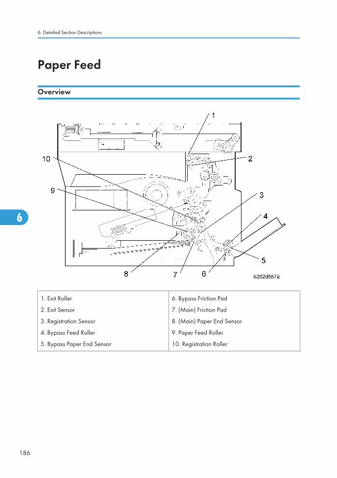
Paper Feed
Overview
1. Exit Roller
2. Exit Sensor
3. Registration Sensor
4. Bypass Feed Roller
5. Bypass Paper End Sensor
6. Bypass Friction Pad
7. (Main) Friction Pad
8. (Main) Paper End Sensor
9. Paper Feed Roller
10. Registration Roller
6. Detailed Section Descriptions
186
6

Paper Feed Drive Mechanism
From Paper Tray
Main motor [A] drives gears on the registration clutch [B] and the paper feed clutch [C]. These clutchestransfer drive to the registration roller [D] and paper feed roller [E]. The BICU controls clutch timing basedon input from the registration sensor.
Paper Feed
187
6

From 100-Sheet Bypass Tray
Main motor [A] drives gear on registration clutch [B] and bypass feed clutch [F]. The bypass feed clutchdrives the bypass feed roller [G]. Again, the BICU controls clutch timing based on input from the registrationsensor.
From 1-Sheet Bypass Tray
The user inserts the sheet directly up to the registration roller [D]. Main motor [A] drives the gear on regis-tration clutch [B], causing the registration roller to turn and feed the sheet.
6. Detailed Section Descriptions
188
6

Paper Feed and Separation
The machine uses a friction-pad feed system.
Friction pad (in paper tray)
Paper Lift Mechanism
When tray is pushed in: Projection [B] on frame pushes rounded slider [C] in against spring [D], retractingthe latch [E]. Spring [F] pushes the plate up.
Paper Feed
189
6

Paper End Detection
Main Tray
When paper runs out, feeler [A] drops into cutout, activating paper end sensor [B].
100-Sheet Bypass Tray
When paper runs out, feeler [C] drops into cutout, activating the bypass paper end sensor [D].
6. Detailed Section Descriptions
190
6

Paper Registration
The BICU uses input from registration sensor [A] to control clutch timing and detect misfeeds. Registrationclutch timing is controlled to eliminate skew (by stopping the paper briefly as it reaches the roller, so thatit buckles). The amount of buckle can be adjusted with SP1-003.
Paper Feed
191
6

Image Transfer and Paper Separation
Overview
The transfer roller [A] is pressed against the OPC drum [B]. The high-voltage power supply board [C]supplies a positive current to the transfer roller, attracting the toner from the drum onto the paper. The currentis set in accordance with the paper's type, size, and feed tray.
Separation of the paper from the drum is aided by the drum's own curvature and by a high AC voltageapplied to the discharge plate [D].
The drum drives the transfer roller directly by gears [E], [F].
Image Transfer Current Timing
There are two transfer current levels: low and high.
6. Detailed Section Descriptions
192
6

1. Low level: Before image transfer starts, the high voltage supply board supplies +10μA to the transferroller. This prevents the transfer roller from attracting any positively charged toner on the drum surface.
2. High level: During image transfer, the high voltage supply board supplies a high level current (seethe table) to the transfer roller. This enables the transfer roller to attract toner onto the paper.
When the trailing edge of the paper has passed the transfer roller, the high voltage supply board stopssupplying the transfer current. If the copier is printing more pages, the high voltage supply board suppliesthe low level current.
You can adjust these levels (* SP2-301). When increasing a transfer current level, use caution:
• Increasing a transfer current level may produce ghost images–some part of image near the leadingedge reappears in other part of the page.
• Increasing a transfer current level might damage the OPC drum.
The table lists the default settings and SPs.
Job type Amp SP
Normal paper 0 μA SP2-301-001
Thick paper 0 μA SP2-301-002
Duplex copying 0 μA SP2-301-003
Transfer Roller Cleaning
Toner may transfer to the roller surface following a paper jam or if the paper is smaller than the image.Periodic cleaning of the roller is required to prevent this toner from migrating back to the rear of newprintouts.
The machine cleans the roller at the following times:
• After initial power on.
• After clearing of a copy jam
• At the end of a job, if at least 10 sheet have been printed since the last cleaning
The high voltage supply unit first supplies a negative cleaning current (about –4 μA) to the transfer roller,causing negatively charged toner on the roller to move back to the drum. It then applies a positive cleaningcurrent (+5 μA) to the roller, causing any positively charged toner to migrate back to the drum.
The cleaning current can be adjusted using SP2-301-4.
Image Transfer and Paper Separation
193
6

Image Fusing and Paper Exit
Overview
1. Exit Roller
2. Paper Path Sensor
3. Hot Roller Strippers
4. Pressure Spring
5. Pressure Roller
6. Fusing Lamp
7. Hot Roller
8. Thermoswitch
9. Thermistor
10. Exit Sensor
6. Detailed Section Descriptions
194
6

Hot Roller Drive
Left: Contact-release solenoid offRight: Contact-release solenoid on
Mechanism
The main motor [A] drives the hot roller [D] through a gear train. One of the gears in the gear train is thecontact-release gear [B]. This gear is linked to the contact-release solenoid [C]. When the contact-releasesolenoid is on, it separates the contact-release gear from another gear [E] in the gear train. As a result, thedrive power of the main motor is not transmitted to the hot roller.
The drive power of the main motor is not transmitted to the paper exit roller [F]. This roller is driven by theduplex motor.
Contact/Release Control
The contact-release solenoid turns on when the following conditions are all met:
• The copier is warming up the hot roller.
• The hot roller temperature is 16°C or higher.
• The fusing idling (SP1-103-001) is “No.”
This control is based on the following facts:
Image Fusing and Paper Exit
195
6

• The copier takes a shorter time to heat the hot roller when the roller is not turning.
• The temperature of the hot roller surface may become uneven when the hot roller temperature is lowand the roller is not turning.
Pressure Roller
The pressure springs [A] constantly press the pressure roller against the hot roller. As the default, the springsare positioned at the lower notch [B]. If necessary, pressure can be decreased by changing the springs tothe upper notch [C].
Pressure Release
6. Detailed Section Descriptions
196
6

When the right door is opened, part [A] (on each side) pulls open catch [B] (on each side), releasingpressure on the pressure roller, so that it can turn freely to allow removal of jams. When the right door isclosed, part [C] pushes catch [B] closed, restoring normal pressure.
Separation
The hot roller stripper pawls [A] prevent paper from sticking to the hot roller.
Fusing Temperature Control
Control Process
The BICU references the signal from the thermistor every second. The BICU turns the fusing lamp on andoff based on the current temperature and the “target temperature”.
Target Temperature
The table lists the target temperatures. You can change these targets by the listed programs.
For the fusing temperature transition during copying, see (below).
Status/Condition Temperature SP
Image Fusing and Paper Exit
197
6

Warming up 160°C SP1-105-001
Ready 150°C SP1-105-003
Copying 160°C SP1-105-005
Low level 60°C SP1-105-007
Thick paper 165°C SP1-105-009
Temperature Transition
When the fusing unit is cool, the fusing temperature should be higher to ameliorate the fusing quality. Duringcopying, the fusing temperature is controlled in four phases as listed in the table. “Default” is the targetfusing temperature of SP1-105-005 (160°C). “Example” is the target fusing temperature of the case whereyou specify “165°C” in SP1-105-005.
Start key pushed(À)
For onesecond (Á)
30 secondslater (Â)
60 secondslater (Ã)
Default 175°C 170°C 165°C 160°C
Example 180°C 175°C 170°C 165°C
Difference fromSP1-105-005
+15°C +10°C +5°C —
Copy SP1-105-005 adjusts the fusing temperature of the fourth phase (Ã). You cannot directly adjust thefusing temperature in the first three phases (À through Â). They are always higher than the fourth phase(Ã) by 15°C, 10°C, and 5°C respectively.
6. Detailed Section Descriptions
198
6

Overheat Protection
The BICU references the fusing temperature through the thermistor [A]. The copier prevents overheating aslisted below. Normally, Feature 1 is effective in preventing overheating. Features 2 through 3 are fail-safefeatures.
Feature 1:
The BICU turns off the fusing lamp when the fusing temperature is too high.
Feature 2:
The BICU disables the machine operation when the thermistor detects an abnormal temperature transition.In a case like this, the copier displays one of these codes: SC543, SC544, SC545, or SC546.
If the fusing temperature is too low, SC542 is displayed.
Feature 3:
The BICU disables the machine operation when the thermistor does not normally work. In a case like this,the copier displays SC541.
Feature 4:
The thermoswitch near the center [B] cuts power to the fusing lamp at 160°C; the thermoswitch near theend [C] cuts power to the fusing lamp at 170°C. These thermoswitches and the fusing lamp are on thesame circuit.
• Thermoswitch temperature is somewhat lower than the fusing temperature.
Image Fusing and Paper Exit
199
6

• The thermoswitch near the center does not necessarily work earlier than the other thermoswitch. Theends of the hot roller can be much hotter than the center when, for example, paper of a small size iscontinuously going through the fusing unit.
Feature 5:
The BICU disables machine operation when the exhaust fan is not functioning normally. In a case like this,the copier displays SC590. Note that defective exhaust fans may cause overheating.
6. Detailed Section Descriptions
200
6

Duplex Unit
Important Components
The following components play important roles in duplex printing:
• The duplex motor drives the exit roller [A] and duplex roller [D].
• One of the paper guides on the fusing unit [C] is linked to the paper path sensor [B].
The bypass tray cannot be used for duplex printing.
Duplex Unit
201
6

Duplex Printing Process
The main steps of the duplex printing process are as follows:
1. The controller starts to operate the main motor and duplex motor.
2. The hot roller [A] and pressure roller [B] transport the paper to the paper guide [C].
3. The leading edge of the paper pushes the paper guide; the paper guide turns the paper path sensor[D] on.
4. When the leading edge of the paper reaches the exit roller [E], the exit roller transports the paper.
5. When the trailing edge of the paper exits from the paper guide, the paper guide drops to the originalposition [F] and turns the paper path sensor [G] off.
6. The controller starts to operate the duplex motor in reverse; the exit roller [H] turns in reverse, trans-porting the paper to the duplex roller.
7. The paper goes over the paper guide and reaches the duplex roller [I].
8. The duplex roller transports the paper into the duplex unit. The paper goes through the unit.
6. Detailed Section Descriptions
202
6

9. When the leading edge of the paper reaches the registration sensor [J], the controller stops the duplexmotor. The duplex roller holds the paper in the duplex unit.
10. When the OPC drum [K] gets ready for printing, the controller restarts the duplex motor. The duplexroller transports the paper.
11. The duplex roller keeps transporting the paper until the paper reaches the fusing unit.
12. The hot and pressure rollers transport the paper to the paper guide.
Duplex Unit
203
6

13. The leading edge of the paper pushes the paper guide [L]; the paper guide turns the paper pathsensor [M] on.
14. The controller changes the direction of the duplex motor. The exit roller [N] changes the direction ofits rotation, transporting the paper to the copy tray.
6. Detailed Section Descriptions
204
6

Energy Saver ModesThis section explains the energy saver modes.
Overview
The machine has two energy-saver modes: the Low Power Mode and the Night/Off Mode. The table liststhe status of several components.
Operation panel Engine Exhaust fan
Operating Mode* On On On
Low Power Mode Off On Off
Night/Off Mode Off Off** Off
* The “Operating Mode” here refers to all the modes (and status) other than the Low Power Mode andNight/Off Mode. Actual power consumption (during the Operating Mode) depends on job status andenvironmental conditions.
Energy Saver Modes
205
6

** The SRAM is alive and backs up the engine controller.
AOF
When AOF is off, the engine controller is unable to start the Night/Off Mode. The user should keep AOFon ( → System Settings → Key Operator Tools → AOF).
Timers
The engine controller references the Energy Saver Timer to start the Low Power Mode, and references theAuto Off Timer to start the Night/Off Mode. The user can set these timers ( → System Settings → TimerSettings).
The Energy Saver Timer and the Auto Off Timer start at the same time (t0) when the machine ends all jobsor when the user ends all manual operations. Note that the Auto Off Timer does not wait for the EnergySaver Timer. If the user specifies a larger value in the Energy Saver Timer, the Auto Off Timer expires earlierthan the Energy Saver Timer. In a case like this, the Low Power Mode is not activated. Instead, the enginecontroller starts the Night/Off Mode when the Auto Off Timer expires.
Specified value Low Power Mode Night/Off Mode
Energy Saver Timer > Auto Off Timer Cannot start Can start
Energy Saver Timer = Auto Off Timer Cannot start Can start
Energy Saver Timer < Auto Off Timer Can start Can start
Recovery
Any of the following operations brings the machine back to the Operating Mode:
• The power switch is pressed.
• Originals are set on the document feeder.
• The platen cover is opened.
6. Detailed Section Descriptions
206
6

GDI ControllerThe GDI controller is standard for the B280 and B293 models. For the B262 and B292 models, the GDIcontroller can be installed as an optional unit.
Overview
B280 (Without Network Interface Card)
GDI Controller
207
6

B293 (With Network Interface Card)
This machine uses the GDI controller to enable the printer features.
Main components:
CPU: D8701
Flash ROM: 1MB/4MB
SDRAM: 32MB/64MB 96MHz
NVRAM(8KB): Stores the controller setting
NVRAM(128MB):Store the MAC address
USB: NET2282
Optional components:
PCL Board
6. Detailed Section Descriptions
208
6

Controller Functions
Paper Source Selection
Tray Priority (Auto Tray Select):
The Tray Priority setting determines the start of the tray search when the user selects “Auto Tray Select” withthe driver.The machine searches for a paper tray with the specified paper size and type.
When no tray contains paper that matches the paper size and type specified by the driver, the controllerstops printing until the user loads the correct paper.
The Tray Priority setting can be specified using the Paper Size Setting in the user tools. (User Tools/ SystemSettings/ Paper Size Settings)
The by-pass tray is not part of the tray search.
Tray Lock:
If Tray Lock is enabled for a tray, the controller skips the “locked” tray in the tray search process.
The Tray Lock setting can be specified by selecting “No” for the “Apply Auto Paper Select” setting in thePaper Size Setting screen in the user tools. (User Tools/ System Settings/ Paper Size Settings)
The by-pass feeder cannot be locked.
Manual Tray Select:
If the selected tray does not have the paper size and type specified by the driver, the controller stops printinguntil the user loads the correct paper.
Auto Continue
When this function is enabled, the machine stops printing and cancels the print job if there is no paper traywhich matches the paper size and paper type specified by the driver.
If Auto Continue is enabled, the machine waits for a specified period (0, 1, 5, 10, 15 minutes) for thecorrect size paper to be set in the tray, then cancels the print job if the interval expires.
GDI Controller
209
6

• The interval can set with the Printer Settings in the user tools. (User Tools/ Printer Settings/ System/Auto Continue)
If Auto Continue is disabled, the machine will not print the job, but will not cancel it, so the job stays in theprint queue.
The default setting for Auto Continue is “Off.”
Duplex Printing
Duplex printing is available with all output bin options but not all paper sizes. If a job specifies duplexprinting but the paper size to be used cannot be used by the duplex unit, the job will be printed single-sided.
• When the by-pass feeder is selected as the paper source, duplex printing is automatically disabled.
Scanner Functions
Image processing for scanner mode
The image processing for scanner mode is done in the IPU chip on the BICU board. The IPU chip choosesthe most suitable image processing methods (gamma tables, dither patterns, etc) depending on the settingsmade in the driver.
6. Detailed Section Descriptions
210
6

The image compression method can be selected with SP mode (MR/MH/MMR for binary picture pro-cessing).
Image Data Path:
1. Image Store/Image Delivery Mode
The user can select the following modes from the LCD.
• Delivery only
After image processing and image compression, all image data for the job are stored in the printercontroller RAM using TIFF file or PDF file format (binary picture processing). The type of TIFF or PDFformat used depends on the user’s scanner settings.
When delivery mode is selected, the controller creates a file which contains the destination and pageinformation, then the controller sends the file to a server.
2. Twain Mode
After image processing and image compression, the data (TIFF or PDF) is sent to the scanner Twaindriver directory on the computer.
Network Interface
LED Indicators
The LED is on the optional controller box.
GDI Controller
211
6

Description On Off
LED1 (Green): Link status Link success Link failure
LED2 (Yellow): Data rate 100 Mbps 10 Mbps
USB
Specifications
USB connectivity is provided as an option for this machine.
Interface: USB 1.1, USB 2.0
Data rates: 480 Mbps (high speed), 12 Mbps (full speed)
High speed mode is only supported by USB 2.0.
USB 1.1/2.0
USB (Universal Serial Bus) offers simple connectivity for computers, printers, keyboards, and other pe-ripherals. In a USB environment, terminators, device IDs (like SCSI), and DIP switch settings are notnecessary.
USB 1.1 provides the following features:
• Plug & Play. As soon as a new device is connected via USB, the operating system recognizes it, andthe appropriate driver is installed for it automatically if the driver is available. If the driver is notavailable, a message prompts the user for the driver disk for immediate installation.
• Hot swapping (cables can be connected and disconnected while the computer and other devices areswitched on)
• No terminator or device ID required
• Data rates of 12 Mbps (full speed)
• Common connectors for different devices
6. Detailed Section Descriptions
212
6

• Bi-directional data communication between device and host computer via a 4-byte header and DE-VICE ID.
USB 2.0 is an evolution of the USB 1.1 specification. It uses the same cables, connectors, and softwareinterfaces so the user will see no change. It provides an easy-to-use connection to a wide range of productswith a maximum data rate of 480 Mbps (high speed).
Up to 127 devices can be connected and 6 cascade connections are allowed. Power is supplied from thecomputer and the maximum cable length is 5 m.
USB connectors
USB is a serial protocol and a physical link, which transmits all data on a single pair of wires. Another pairprovides power to downstream peripherals. The USB standard specifies two types of connectors, type “A”connectors for upstream connection to the host system, and type “B” connectors for downstream connectionto the USB device.
[A]: Type “A” connector, [B]: Type “B” connector
Pin Assignment
The controller has a type “B” receptacle.
Pin No. Signal Description Wiring Assignment
GDI Controller
213
6

1 Power Red
2 Data – White
3 Data + Green
4 Power GND White
Remarks about USB
The machine does not print reports specifically for USB.
Only one host computer is allowed for the USB connection.
After starting a job using USB, do not switch the printer off until the job has been completed. When a usercancels a print job, if data transmitted to the printer has not been printed at the time of cancellation, thejob will continue to print up to the page where the print job was cancelled
When the controller board is replaced, the host computer will recognize the machine as a different device.
Related SP Mode
“USB Settings” in the printer engine service mode. Data rates can be adjusted to full speed fixed (12 Mbps).This switch may be used for troubleshooting if there is a data transfer error using the high speed mode (480Mbps).
Data rates can also be adjusted using the UP mode “USB Setting” in the Host Interface in the System menu.This mode can be accessed only when the “Enter”, “Escape”, then “Menu” keys are pressed to enter theUP mode.
NVRAM on the GDI Controller
• Socket type
• When the GDI controller is replaced, remove the NVRAM from the old GDI controller and install iton the new GDI controller. NVRAM keeps machine-specific data (IP address and controller setting).
6. Detailed Section Descriptions
214
6

7. Specifications
General Specifications
Copier
Configuration: Desktop
Copy Process: Laser beam scanning and electro photographic printing
Originals: Sheet/Book/Object
Original Size:
Maximum
A4 / 81/2" x 14"A4 / 81/2" x 14" (ARDF)
Copy Paper Size:
Maximum
A4 SEF / 81/2" x 11" SEF (Copier's paper tray)A4 SEF / 81/2" x 14" SEF (Bypass)A4 SEF / 81/2" x 14" SEF (Optional paper tray)A4 SEF / 81/2" x 14" SEF (Duplex)
Minimum
A5 LEF / 81/2" x 51/2" LEF (Copier's paper tray)A6 SEF/ 81/2" x 51/2" (Bypass)A4 SEF / 81/2" x 11” SEF (Optional paper tray unit)A4 SEF / 81/2" x 11” SEF (Duplex)
Custom sizes in the bypass tray:
Width: 90 – 216 mm (3.5" – 8.5")Length: 139 – 600mm (5.48" – 23.62")
Copy Paper Weight:
Standard paper tray; optional paper tray:
60 – 90 g/m2, 16 – 24 lb.
Bypass:
60 – 157 g/m2, 16 – 42 lb.
Duplex:
64 – 90 g/m2, 20 – 24 lb.
Reproduction Ratios: A4 Version LT Version
215
7

Enlargement200%
141%
155%
129%
Full Size 100% 100%
Reduction
93%
71%
50%
93%78%
65%
Zoom: 50% to 200%, in 1% steps
Power Source: 110 – 120 V, 60 Hz or 220 – 240 V, 50/60 Hz
Power Consumption:Maximum: 900 W or lessEnergy Saver: 25 W or lessOff Mode: 1 W or less
Noise Emission:
Sound Power Level
Standby 40 dB(A) or less
Operating (copier only) 62 dB(A) or less
Operating (full-system) 66 dB(A) or less
Dimensions (W x D x H)Copier: 485 x 450 x 371 mm (19.4" x 18" x 14.8")With optional paper tray unit: 485 x 454 x 511 mm (18.4" x 17.7" x20.1")
Weight:
Basic: 22 kg (48.5 lb.) or less
Basic with ARDF: 27 kg (59.4 lb.) or less
GDI model: 24 kg (52.8 lb.) or less
Resolution: 600 dpi
Copying Speed in MulticopyMode (copies/minute):
16 (A4 / 81/2" x 11"; 100%)
Warm-up Time:Basic: 10 seconds or less (at 20°C [68°F])
Other: Approximately 35 seconds (at 20°C [68°F])
First Copy Time:
7.5 seconds or less
Note: Measurement conditions
• From the ready state, with the polygonal mirror motor spinning.
• A4/LT copying
7. Specifications
216
7

• From copier's paper tray
• 100% size
Copy Number Input: Numeric keypad, 1 to 99 (increment, decrement)
Manual Image Density: 5 steps
Auto Off TimerDefault: 1 minuteRange: 1 to 240 minutes
Energy Saver Timer:Default: 1 minuteRage: 1 to 240 minutes
Copy Paper Capacity:
Paper Tray: 250 sheets
Optional Paper Tray Unit: 500 sheets x 1Bypass Tray: 100 sheets
Copy-Tray Capacity 250 sheets
Toner Replenishment: Cartridge replacement (230 g/cartridge)
Toner Yield 7k copies /toner bottle (A4, 6% full black)
Optional Equipment:
Auto reverse document feeder
Paper tray unit
Anti-condensation heater for paper tray unit
Printer
Resolution 600 dpi
Printing speed 16 ppm (A4L, 8½" × 11"L plain paper)
InterfaceUSB 2.0 interface,
Ethernet interface (100BASE-TX/10BASE-T)
Network protocol TCP/IP, IPP
Printer language Host-Based Printing
Memory 64 MB
Operating systems supportedby this machine
Windows 98SE / Me
Windows 2000
General Specifications
217
7

Windows XP
Windows Server 2003
Required network cable
100BASE-TX/10BASE-T shielded twisted-pair (STP, Category/Type5)
cable.
Scanner
Scan method Flatbed scanning
Scan speed *1
Approx. 18 pages/minute [Scan size: A4SEF, Colors/Gradations: Bi-nary, Resolution: 200dpi,
Select device data compression (Binary/Halftone): Data compression(MMR),
Document feeder: ARDF, ITU-T No.1 Chart]
Maximum power consump-tion
Less than 900 W
Image sensor type CCD Image Sensor
Scan types Sheet, book
InterfaceUSB interface,
Ethernet interface (10BASE-T or 100BASE-TX)
ResolutionB/W: 600 dpi
Full color: 300 dpi (600 dpi with the optional DIMM)
Variable range of scan reso-lution
Setting range: 100 dpi - 600 dpi
*1 Scanning speeds vary according to machine operating conditions, computer (specifications, networktraffic, software, etc.), and original types.
ARDF
Original Size:Standard:
A4 to A5; 81/2" x 14" to 81/2" x 51/2"
7. Specifications
218
7
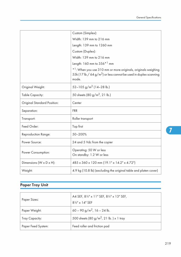
Custom (Simplex):
Width: 139 mm to 216 mm
Length: 139 mm to 1260 mm
Custom (Duplex):
Width: 139 mm to 216 mm
Length: 160 mm to 356*1 mm
*1: When you use 310 mm or more originals, originals weighing55k (17 lb./ 64 g/m2) or less cannot be used in duplex scanningmode.
Original Weight: 52–105 g/m2 (14–28 lb.)
Table Capacity: 50 sheets (80 g/m2, 21 lb.)
Original Standard Position: Center
Separation: FRR
Transport: Roller transport
Feed Order: Top first
Reproduction Range: 50–200%
Power Source: 24 and 5 Vdc from the copier
Power Consumption:Operating: 50 W or lessOn standby: 1.2 W or less
Dimensions (W x D x H): 485 x 360 x 120 mm (19.1" x 14.2" x 4.72")
Weight: 4.9 kg (10.8 lb) (excluding the original table and platen cover)
Paper Tray Unit
Paper Sizes:A4 SEF, 8½" x 11" SEF, 8½" x 13" SEF,
8½" x 14" SEF
Paper Weight: 60 – 90 g/m2, 16 – 24 lb.
Tray Capacity: 500 sheets (80 g/m2, 21 lb. ) x 1 tray
Paper Feed System: Feed roller and friction pad
General Specifications
219
7

Power Source:
24 Vdc and 5 Vdc, from copier. If optional tray heater is installed,the copier also supplies Vac (120 Vac or
220 – 240 Vac).
Power Consumption: Maximum: 15 W (excluding optional tray heater)
Average: 14 W (excluding optional tray heater)
Weight: Not above 6 kg (13.2. lb.)
Size (W x D x H): 430 x 414 x 140 mm (16.9" x 16.3" x 5.5")
7. Specifications
220
7

Supported Paper Sizes
Original Paper Sizes
The copier and ARDF do not detect original paper sizes. The following table lists the paper sizes that theARDF can transport.
Paper Size (W x L) BookARDF
Simpl. Dupl.
A3 SEF 297 x 420 mm – – –
B4 SEF 257 x 364 mm – – –
A4 SEF 210 x 297 mm X X X
A4 LEF 297 x 210 mm –
B5 SEF 182 x 257 mm X X X
B5 LEF 257 x 182 mm –
A5 SEF 148 x 210 mm X X X
A5 LEF 210 x 148 mm X X
B6 SEF 128 x 182 mm –
B6 LEF 182 x 128 mm –
A6 SEF 105 x 148 mm –
8K SEF 267 x 390 mm –
16K SEF 195 x 267 mm X X X
16K LEF 267 x 195 mm –
DLT SEF 11.0" x 17.0" –
LG SEF 8.5" x 14.0" X*1 X X*2
LT SEF 8.5" x 11.0" X X X
LT LEF 11.0" x 8.5" –
Executive SEF 7.25" x 10.5" – X X
Supported Paper Sizes
221
7

Paper Size (W x L) BookARDF
Simpl. Dupl.
HLT SEF 5.5" x 8.5" X X X
HLT LEF 8.5" x 5.5" X X
F/GL (F4) SEF 8.0" x 13.0" X*1 X X*2
Foolscap SEF 8.5" x 13.0" X*1 X X*2
Folio SEF 8.25" x 13.0" X*1 X X*2
Government 8.25" x 14" X*1 X X*2
USB4 SEF 10.0" x 14.0" –
Eng Quarto SEF 8.0" x 10.0" – X X*2
Eng Quarto LEF 10.0" x 8.0" –
Custom:Width 139-216 mm
Length 139-356 mm– X*3 X*2, 4
Symbol meanings:
X: Can use
–: Cannot use
*1: Can be used when the ARDF is installed
*2: 55k (17 lb./ 64 g/m2) or less original cannot be used.
*3: Width: 139-216 mm, Length: 139-1260 mm
*4: Width 139-216 mm, Length: 160-356 mm
Paper Feed
The copier and optional paper feed unit do not detect paper sizes. The following table lists the paper sizesthat the copier and optional paper feed unit can transport.
Paper Size (W x L) Regular By-pass Duplex Optional PFU
A3 SEF 297 x 420 mm – – – –
B4 SEF 257 x 364 mm – – – –
7. Specifications
222
7

Paper Size (W x L) Regular By-pass Duplex Optional PFU
A4 SEF 210 x 297 mm X X X X
A4 LEF 297 x 210 mm – – – –
B5 SEF 182 x 257 mm X X X –
B5 LEF 257 x 182 mm – – – –
A5 SEF 148 x 210 mm – X – –
A5 LEF 210 x 148 mm X X – –
B6 SEF 128 x 182 mm – – – –
B6 LEF 182 x 128 mm – – – –
A6 SEF 105 x 148 mm – – – –
8K SEF 267 x 390 mm – – – –
16K SEF 195 x 267 mm X X X –
16K LEF 267 x 195 mm – – – –
DLT SEF 11.0" x 17.0" – – – –
LG SEF 8.5" x 14.0" – X X X
LT SEF 8.5" x 11.0" X X X X
LT LEF 11.0" x 8.5" – – – –
Executive SEF 7.25" x 10.5" – X – –
HLT SEF 5.5" x 8.5" – X – –
HLT LEF 8.5" x 5.5" X X – –
F/GL (F4) SEF 8.0" x 13.0" – X – –
Foolscap SEF 8.5" x 13.0" – X X X
Folio SEF 8.25" x 13.0" – X X X
Government 8.25" x 14" – X X X
USB4 SEF 10.0" x 14.0" – – – –
Eng Quarto SEF 8.0" x 10.0" – – – –
Supported Paper Sizes
223
7

Paper Size (W x L) Regular By-pass Duplex Optional PFU
Eng Quarto LEF 10.0" x 8.0" – – – –
Custom: Leading edge 90–216 mm
Side edge 139–356 mm– X – –
Symbol meanings:
X: Can transport
–: Cannot transport
7. Specifications
224
7

Machine Configuration
Basic Model (B262/B292)
Standard Component Machine Code Remarks
1 Copier [A] B262/B292 -
Optional Components Machine Code Remarks
2 500-Sheet Paper Feed Unit [B] B421 -
3 DDST Unit [C] B880/B893 -
Standard/Optional Component Machine Code Remarks
4 ARDF [D] B872• Standard for B292
• Optional for others
Machine Configuration
225
7

GDI Model (B280/B293)
Standard Component Machine Code Remarks
1 Copier [A] B280/B293 -
- DDST Unit [C] - Standard for B280/B293
Optional Components Machine Code Remarks
2 500-Sheet Paper Feed Unit [B] B421
3 ARDF [D] B872 -
4 256MB/SDRAM/DIMM (PC133) [E] G332 -
7. Specifications
226
7

MEMO
227

MEMO
228


