• Tools Required to Assemble an MP8000 Actuator to a Valve Body 4
• Theory of Operation 5
Mounting Procedure 7
• Mounting to VG2000 Series and V-5000 Series Iron Valves 7
• Mounting to VG7000 Series Bronze Control Valves 14
Reversing the Action of the MP8000 Actuator 23
• Reversing From Spring-Return-Up to Spring-Return-Down 23
• Reversing From Spring-Return-Down to Spring-Return-Up 24
MP8000 Actuator Maintenance and Repair 25
MP8000 Series Pneumatic Valve Actuators
2 Actuators and Positioners Product Information—MP8000 Series Pneumatic Valve Actuators
Actuators and Positioners Product Information—MP8000 Series Pneumatic Valve Actuators 3
Pre-Assembly Details
A
B
CD
E
F
G
H
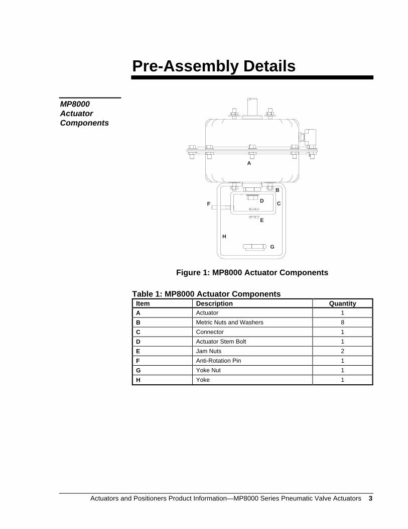
Figure 1: MP8000 Actuator Components
Table 1: MP8000 Actuator Components Item Description Quantity A Actuator 1 B Metric Nuts and Washers 8 C Connector 1 D Actuator Stem Bolt 1 E Jam Nuts 2 F Anti-Rotation Pin 1 G Yoke Nut 1 H Yoke 1
MP8000 Actuator Components
4 Actuators and Positioners Product Information—MP8000 Series Pneumatic Valve Actuators
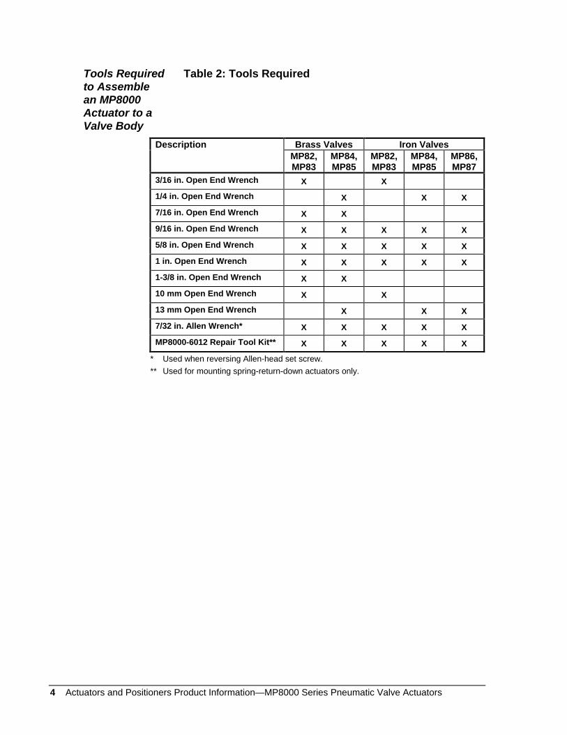
Table 2: Tools Required
Description Brass Valves Iron Valves MP82, MP83
MP84, MP85
MP82, MP83
MP84, MP85
MP86, MP87
3/16 in. Open End Wrench X X
1/4 in. Open End Wrench X X X
7/16 in. Open End Wrench X X
9/16 in. Open End Wrench X X X X X
5/8 in. Open End Wrench X X X X X
1 in. Open End Wrench X X X X X
1-3/8 in. Open End Wrench X X
10 mm Open End Wrench X X
13 mm Open End Wrench X X X
7/32 in. Allen Wrench* X X X X X
MP8000-6012 Repair Tool Kit** X X X X X
* Used when reversing Allen-head set screw. ** Used for mounting spring-return-down actuators only.
Tools Required to Assemble an MP8000 Actuator to a Valve Body
Actuators and Positioners Product Information—MP8000 Series Pneumatic Valve Actuators 5
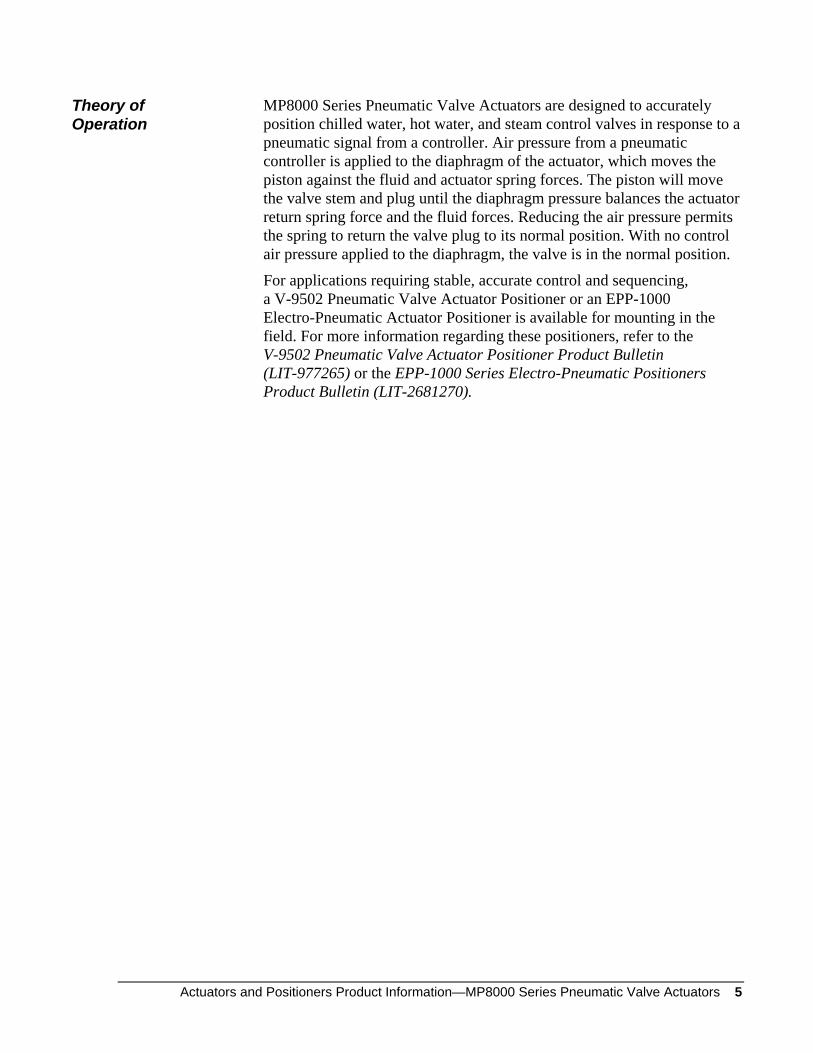
MP8000 Series Pneumatic Valve Actuators are designed to accurately position chilled water, hot water, and steam control valves in response to a pneumatic signal from a controller. Air pressure from a pneumatic controller is applied to the diaphragm of the actuator, which moves the piston against the fluid and actuator spring forces. The piston will move the valve stem and plug until the diaphragm pressure balances the actuator return spring force and the fluid forces. Reducing the air pressure permits the spring to return the valve plug to its normal position. With no control air pressure applied to the diaphragm, the valve is in the normal position.
For applications requiring stable, accurate control and sequencing, a V-9502 Pneumatic Valve Actuator Positioner or an EPP-1000 Electro-Pneumatic Actuator Positioner is available for mounting in the field. For more information regarding these positioners, refer to the V-9502 Pneumatic Valve Actuator Positioner Product Bulletin (LIT-977265) or the EPP-1000 Series Electro-Pneumatic Positioners Product Bulletin (LIT-2681270).
Theory of Operation
6 Actuators and Positioners Product Information—MP8000 Series Pneumatic Valve Actuators
Actuators and Positioners Product Information—MP8000 Series Pneumatic Valve Actuators 7
Mounting Procedure
When mounting a V-9502 Pneumatic Valve Actuator Positioner or an EPP-1000 Electro-Pneumatic Valve Actuator Positioner to an MP8000 Series Actuator, refer to the instructions included with the positioner.
! CAUTION: Personal Injury Hazard. If the valve body is installed in a system, isolate the valve and bleed off the system pressure. Failure to do so may result in personal injury.
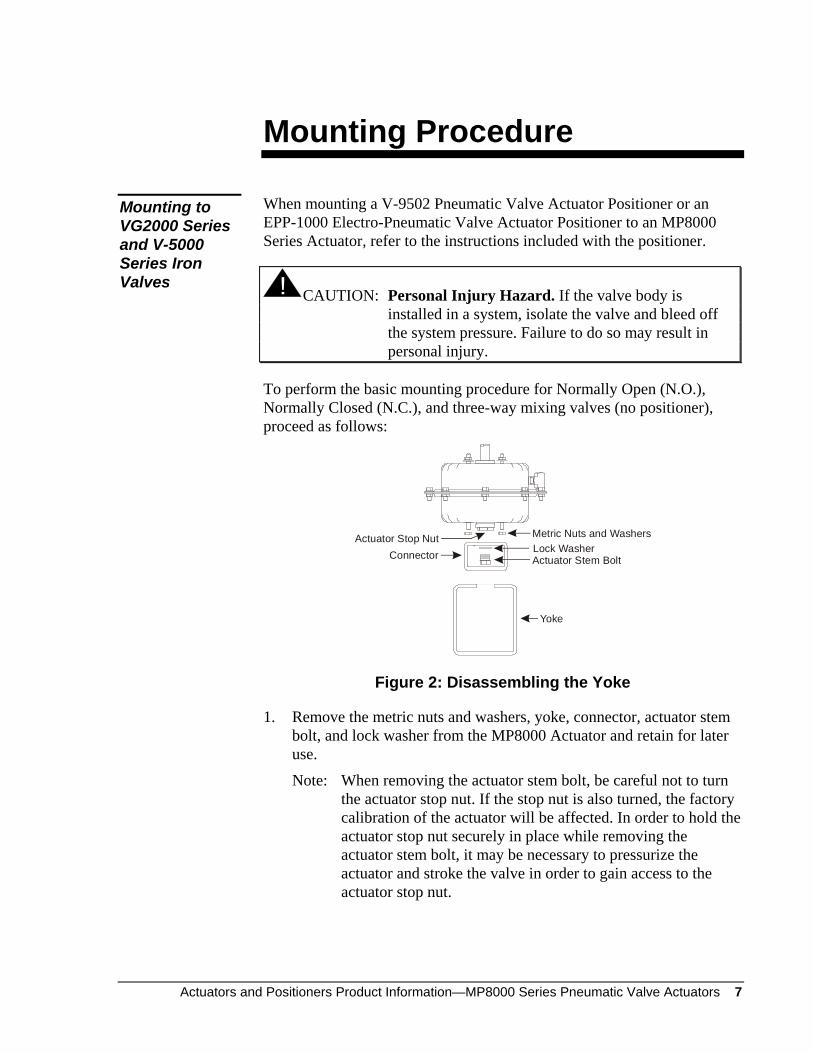
To perform the basic mounting procedure for Normally Open (N.O.), Normally Closed (N.C.), and three-way mixing valves (no positioner), proceed as follows:
Metric Nuts and WashersActuator Stop Nut
Yoke
Actuator Stem BoltLock WasherConnector
Figure 2: Disassembling the Yoke
1. Remove the metric nuts and washers, yoke, connector, actuator stem bolt, and lock washer from the MP8000 Actuator and retain for later use.
Note: When removing the actuator stem bolt, be careful not to turn the actuator stop nut. If the stop nut is also turned, the factory calibration of the actuator will be affected. In order to hold the actuator stop nut securely in place while removing the actuator stem bolt, it may be necessary to pressurize the actuator and stroke the valve in order to gain access to the actuator stop nut.
Mounting to VG2000 Series and V-5000 Series Iron Valves
8 Actuators and Positioners Product Information—MP8000 Series Pneumatic Valve Actuators
Packing NutBonnet Nut
Stem Up
Stem Down
Figure 3: Preparing the Valve
2. Push the valve stem down as far as it will go into the valve.
3. Remove the packing nut and retain.
4. Where applicable, remove and discard the bonnet nut.
Stem Jam NutPacking NutYoke Nut
Yoke
Figure 4: Assembling the Yoke
5. Secure the yoke to the valve bonnet using the yoke nut included with the actuator mounting kit. Position the centering boss of the yoke nut so that it faces the valve (as illustrated in Figure 4). Hand tighten only.
6. Reinstall the packing nut retained in Step 3, and tighten it 1/6 of a turn past hand tight.
7. Thread the lower stem jam nut (included with the valve) fully onto the valve stem.
Actuators and Positioners Product Information—MP8000 Series Pneumatic Valve Actuators 9
ConnectorActuator Stem BoltLock Washer
Actuator Stop Nut
Anti-RotationPin Hole
Figure 5: Attaching the Connector (Spring-Return-Up Models)
8. For spring-return-up models, attach the connector to the actuator stop nut using the 7/16-20 x 7/8 in. actuator stem bolt and lock washer (included with the actuator). Engage the actuator stem bolt approximately three turns into the actuator stop nut; the connector will be loose.
Actuator Stem
ConnectorAnti-Rotation
Pin Hole
Actuator Stem Bolt
Lock Washer
Figure 6: Attaching the Connector (Spring-Return-Down Models)
For spring-return-down models, attach the connector to the actuator stem using the actuator stem bolt and lock washer (included with the actuator). Hand tighten only.
Note: The connector must be oriented so that the holes for the anti-rotation pin are closest to the valve body.
10 Actuators and Positioners Product Information—MP8000 Series Pneumatic Valve Actuators
Metric Nuts andWashers
Threaded Studs
Connector
Yoke
Figure 7: Attaching the Actuator to the Yoke
For spring-return-up action, proceed as follows:
9. Locate the four threaded studs on the actuator housing adjacent to the actuator stop nut, and install the actuator onto the yoke.
10. Secure the actuator to the yoke with the four metric nuts and washers (included with the actuator). Extend the valve stem until it engages the connector and tighten the metric nuts securely. Also hand tighten the actuator stem bolt. The connector should be free to move.
Anti-RotationPin
Connector
Figure 8: Installing the Anti-Rotation Pin
11. Align the connector with the yoke slot and insert the anti-rotation pin. Tighten the anti-rotation pin securely in place.
12. Apply enough supply air to the actuator in order to move the actuator stem bolt down at least 1/8 in. (3 mm), then tighten the actuator stem bolt securely.
Note: Do not rotate the actuator stop nut while tightening the actuator stem bolt; doing so may change the start point of the actuator.
13. Disconnect the supply air.
Spring-Return-Up Models
Actuators and Positioners Product Information—MP8000 Series Pneumatic Valve Actuators 11
1/32 in. Gap
Upper Stem Jam Nut
Lower Stem Jam Nut
Actuator Stop Nut
Figure 9: Securing the Valve Stem
14. Fully extend the valve stem into the connector hole and thread the upper stem jam nut (included with the valve) onto the valve stem, down against the connector.
For N.C. and three-way mixing valves only, tighten the upper stem jam nut until there is a 1/32 in. gap between the actuator stop nut and the brass bearing holder.
15. Thread the lower stem jam nut up against the connector and tighten it securely in place.
16. Tighten the yoke nut securely in place.
17. Apply 20 psig (138 kPa) supply air to the actuator and observe the unit for proper operation.
18. Install the position indicator scale (included with the actuator) so that the top line on the scale is aligned with the center of the anti-rotation pin. Doing so completes the mounting procedure for spring-return-up action.
12 Actuators and Positioners Product Information—MP8000 Series Pneumatic Valve Actuators
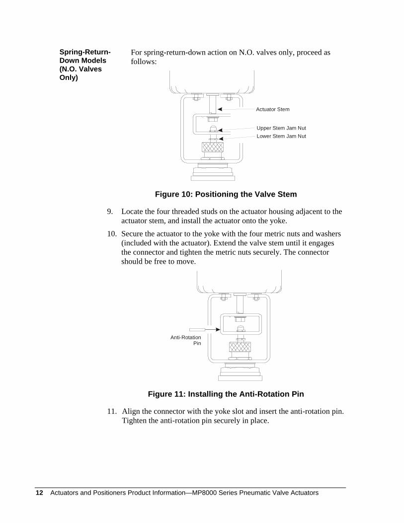
For spring-return-down action on N.O. valves only, proceed as follows:
Upper Stem Jam NutLower Stem Jam Nut
Actuator Stem
Figure 10: Positioning the Valve Stem
9. Locate the four threaded studs on the actuator housing adjacent to the actuator stem, and install the actuator onto the yoke.
10. Secure the actuator to the yoke with the four metric nuts and washers (included with the actuator). Extend the valve stem until it engages the connector and tighten the metric nuts securely. The connector should be free to move.
Anti-RotationPin
Figure 11: Installing the Anti-Rotation Pin
11. Align the connector with the yoke slot and insert the anti-rotation pin. Tighten the anti-rotation pin securely in place.
Spring-Return-Down Models (N.O. Valves Only)
Actuators and Positioners Product Information—MP8000 Series Pneumatic Valve Actuators 13
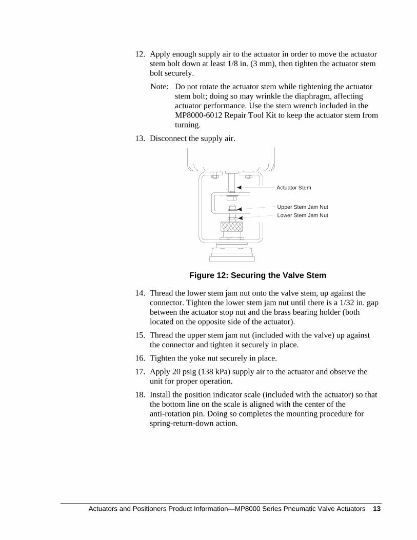
12. Apply enough supply air to the actuator in order to move the actuator stem bolt down at least 1/8 in. (3 mm), then tighten the actuator stem bolt securely.
Note: Do not rotate the actuator stem while tightening the actuator stem bolt; doing so may wrinkle the diaphragm, affecting actuator performance. Use the stem wrench included in the MP8000-6012 Repair Tool Kit to keep the actuator stem from turning.
13. Disconnect the supply air.
Upper Stem Jam NutLower Stem Jam Nut
Actuator Stem
Figure 12: Securing the Valve Stem
14. Thread the lower stem jam nut onto the valve stem, up against the connector. Tighten the lower stem jam nut until there is a 1/32 in. gap between the actuator stop nut and the brass bearing holder (both located on the opposite side of the actuator).
15. Thread the upper stem jam nut (included with the valve) up against the connector and tighten it securely in place.
16. Tighten the yoke nut securely in place.
17. Apply 20 psig (138 kPa) supply air to the actuator and observe the unit for proper operation.
18. Install the position indicator scale (included with the actuator) so that the bottom line on the scale is aligned with the center of the anti-rotation pin. Doing so completes the mounting procedure for spring-return-down action.
14 Actuators and Positioners Product Information—MP8000 Series Pneumatic Valve Actuators
When mounting a V-9502 Pneumatic Valve Actuator Positioner or an EPP-1000 Electro-Pneumatic Valve Actuator Positioner to an MP8000 Series Actuator, refer to the instructions included with the positioner.
! CAUTION: Personal Injury Hazard. If the valve body is installed in a system, isolate the valve and bleed off the system pressure. Failure to do so may result in personal injury.
To perform the basic mounting procedure for Normally Open (N.O.), Normally Closed (N.C.), and three-way mixing valves (no positioner), proceed as follows:
Metric Nuts and WashersActuator Stop Nut
Yoke
Actuator Stem BoltLock WasherConnector
Figure 13: Disassembling the Yoke
1. Remove the metric nuts, washers, yoke, connector, actuator stem bolt, and lock washer from the MP8000 Actuator and retain for later use.
Note: When removing the actuator stem bolt, be careful not to turn the actuator stop nut. If the stop nut is also turned, the factory calibration of the actuator will be affected. In order to hold the actuator stop nut securely in place while removing the actuator stem bolt, it may be necessary to pressurize the actuator and stroke the valve in order to gain access to the actuator stop nut.
Mounting to VG7000 Series Bronze Control Valves
Actuators and Positioners Product Information—MP8000 Series Pneumatic Valve Actuators 15
Packing NutBonnet Nut
Stem Up
Stem Down
Figure 14: Preparing the Valve
2. Push the valve stem down as far as it will go into the valve.
3. Remove the packing nut and retain.
4. Where applicable, remove and discard the bonnet nut.
Stem Jam NutPacking NutYoke Nut
Yoke
Figure 15: Assembling the Yoke
5. Secure the yoke to the valve bonnet using the yoke nut included with the actuator mounting kit. Position the centering boss of the yoke nut so that it faces the valve (as illustrated in Figure 15). Hand tighten only.
6. Reinstall the packing nut retained in Step 3. For brass trim valves, tighten the packing nut 1/6 of a turn past hand tight. For stainless steel trim valves, hand tighten the packing nut all the way.
7. If an MP82 or MP83 Actuator is being mounted to a 1/4 in. stem valve, thread the 1/4 in. stem jam nut (included with the actuator mounting kit) fully onto the valve stem.
If an MP84 or MP85 Actuator is being mounted to a 3/8 in. stem valve, skip to Step 9.
16 Actuators and Positioners Product Information—MP8000 Series Pneumatic Valve Actuators
StemExtender
1/4 in. Jam Nut
3/8 in. Jam Nuts
Figure 16: Installing the Stem Extender
8. Thread the stem extender (included with the actuator mounting kit) fully onto the valve stem.
9. For 1/4 in. stem valves, thread the 3/8 in. stem extender jam nut (included with the actuator mounting kit) onto the stem extender until there is approximately a four-thread gap between the two jam nuts.
For 3/8 in. stem valves, thread the 3/8 in. stem jam nut (included with the actuator mounting kit) fully onto the valve stem.
ConnectorActuator Stem BoltLock Washer
Actuator Stop Nut
Anti-RotationPin Hole
Figure 17: Attaching the Connector (Spring-Return-Up Models)
10. For spring-return-up models, attach the connector to the actuator stop nut using the actuator stem bolt and lock washer (included with the actuator). Engage the actuator stem bolt approximately three turns into the actuator stop nut; the connector will be loose.
Actuators and Positioners Product Information—MP8000 Series Pneumatic Valve Actuators 17
Actuator Stem
ConnectorAnti-Rotation
Pin Hole
Actuator Stem Bolt
Lock Washer
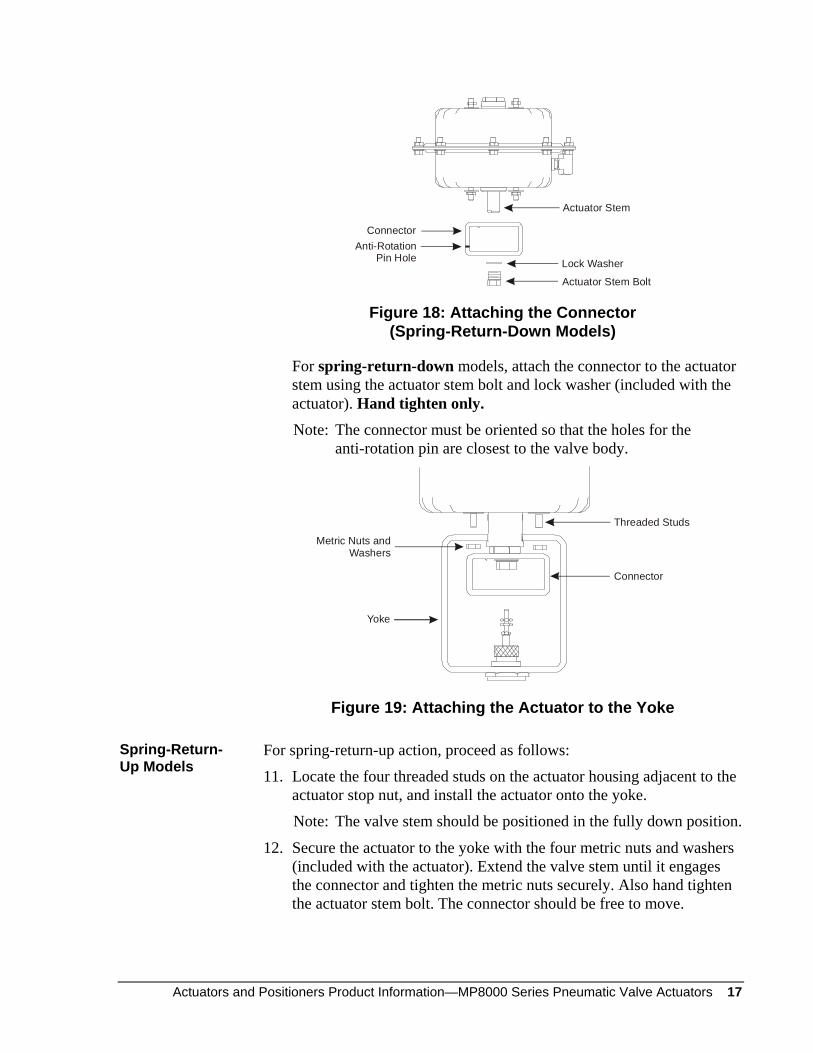
Figure 18: Attaching the Connector (Spring-Return-Down Models)
For spring-return-down models, attach the connector to the actuator stem using the actuator stem bolt and lock washer (included with the actuator). Hand tighten only.
Note: The connector must be oriented so that the holes for the anti-rotation pin are closest to the valve body.
Threaded Studs
Metric Nuts andWashers
Yoke
Connector
Figure 19: Attaching the Actuator to the Yoke
For spring-return-up action, proceed as follows:
11. Locate the four threaded studs on the actuator housing adjacent to the actuator stop nut, and install the actuator onto the yoke.
Note: The valve stem should be positioned in the fully down position.
12. Secure the actuator to the yoke with the four metric nuts and washers (included with the actuator). Extend the valve stem until it engages the connector and tighten the metric nuts securely. Also hand tighten the actuator stem bolt. The connector should be free to move.
Spring-Return-Up Models
18 Actuators and Positioners Product Information—MP8000 Series Pneumatic Valve Actuators
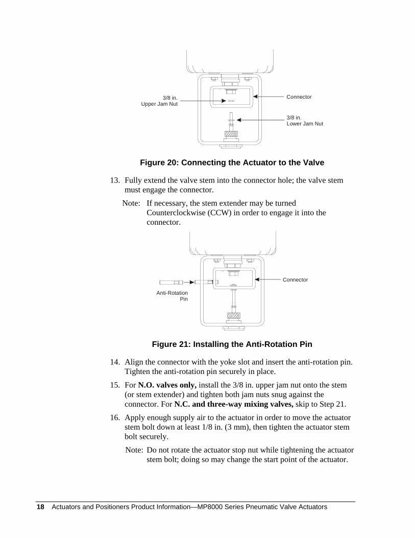
3/8 in.Upper Jam Nut
Connector
3/8 in.Lower Jam Nut
Figure 20: Connecting the Actuator to the Valve
13. Fully extend the valve stem into the connector hole; the valve stem must engage the connector.
Note: If necessary, the stem extender may be turned Counterclockwise (CCW) in order to engage it into the connector.
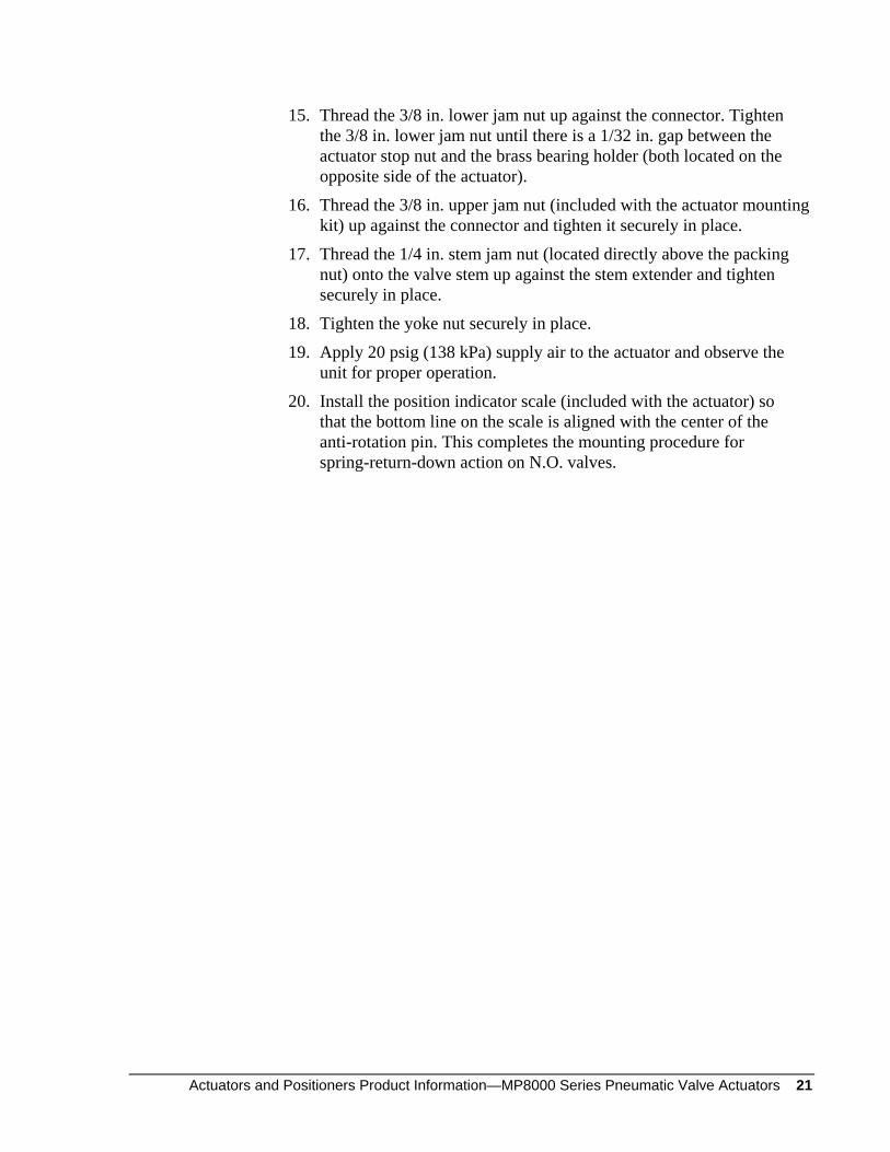
Anti-RotationPin
Connector
Figure 21: Installing the Anti-Rotation Pin
14. Align the connector with the yoke slot and insert the anti-rotation pin. Tighten the anti-rotation pin securely in place.
15. For N.O. valves only, install the 3/8 in. upper jam nut onto the stem (or stem extender) and tighten both jam nuts snug against the connector. For N.C. and three-way mixing valves, skip to Step 21.
16. Apply enough supply air to the actuator in order to move the actuator stem bolt down at least 1/8 in. (3 mm), then tighten the actuator stem bolt securely.
Note: Do not rotate the actuator stop nut while tightening the actuator stem bolt; doing so may change the start point of the actuator.
Actuators and Positioners Product Information—MP8000 Series Pneumatic Valve Actuators 19
17. Tighten the yoke nut securely in place.
18. Apply 20 psig (138 kPa) supply air to the actuator and observe the unit for proper operation.
19. Install the position indicator scale (included with the actuator) so that the top line of the scale is aligned with the center of the anti-rotation pin.
20. Disconnect the supply air. This completes the mounting procedure for spring-return-up action on N.O. valves.
21. For N.C. and three-way mixing valves, thread the 3/8 in. upper jam nut (included with the actuator mounting kit) onto the valve stem (or stem extender), down against the connector. Tighten the 3/8 in. upper jam nut until there is a 1/32 in. gap between the actuator stop nut and the brass bearing holder.
22. Thread the 3/8 in. lower jam nut up against the connector and tighten it securely in place.
23. Tighten the yoke nut securely in place.
24. Apply 20 psig (138 kPa) supply air to the actuator and observe the unit for proper operation.
25. Install the position indicator scale (included with the actuator) so that the top line on the scale is aligned with the center of the anti-rotation pin. This completes the mounting procedure for spring-return-up action on N.C. and three-way mixing valves.
For spring-return-down action on N.O. valves only, proceed as follows:
Actuator Stem
ConnectorAnti-Rotation
Pin Hole
Actuator Stem Bolt
Lock Washer
Figure 22: Positioning the Valve Stem
11. Position the valve stem in order to fully close the valve.
Spring-Return-Down Models (N.O. Valves Only)
20 Actuators and Positioners Product Information—MP8000 Series Pneumatic Valve Actuators
Anti-RotationPin
Figure 23: Installing the Anti-Rotation Pin
12. Align the connector with the yoke slot and insert the anti-rotation pin. Tighten the anti-rotation pin securely in place.
13. Apply enough supply air to the actuator in order to move the actuator stem bolt down at least 1/8 in. (3 mm), then tighten the actuator stem bolt securely.
Note: Do not rotate the actuator stem while tightening the actuator stem bolt; doing so may wrinkle the diaphragm, affecting actuator performance. Use the stem wrench included in the MP8000-6012 Repair Tool Kit to keep the actuator stem from turning.
14. Disconnect the supply air.
1/4 in. Stem Jam Nut
3/8 in. Upper Jam Nut
3/8 in. Lower Jam Nut
Figure 24: Securing the Valve Stem
Actuators and Positioners Product Information—MP8000 Series Pneumatic Valve Actuators 21
15. Thread the 3/8 in. lower jam nut up against the connector. Tighten the 3/8 in. lower jam nut until there is a 1/32 in. gap between the actuator stop nut and the brass bearing holder (both located on the opposite side of the actuator).
16. Thread the 3/8 in. upper jam nut (included with the actuator mounting kit) up against the connector and tighten it securely in place.
17. Thread the 1/4 in. stem jam nut (located directly above the packing nut) onto the valve stem up against the stem extender and tighten securely in place.
18. Tighten the yoke nut securely in place.
19. Apply 20 psig (138 kPa) supply air to the actuator and observe the unit for proper operation.
20. Install the position indicator scale (included with the actuator) so that the bottom line on the scale is aligned with the center of the anti-rotation pin. This completes the mounting procedure for spring-return-down action on N.O. valves.
22 Actuators and Positioners Product Information—MP8000 Series Pneumatic Valve Actuators
Actuators and Positioners Product Information—MP8000 Series Pneumatic Valve Actuators 23
Reversing the Action of the MP8000 Actuator
If required, the action of the MP8000 Actuator mounted on a N.O. valve can be reversed in the field from spring-return-up to spring-return-down or vice versa. Refer to the appropriate section that follows for reversing the action of the MP8000 Actuator.
! CAUTION: Personal Injury Hazard. If the valve body is installed in a system, isolate the valve and bleed off the system pressure. Failure to do so may result in personal injury.
Actuator Stem
ConnectorAnti-Rotation
Pin Hole
Actuator Stem Bolt
Lock Washer
Figure 25: Reassembly for Spring-Return-Down Action
Refer to Figure 25 and proceed as follows:
1. Disassemble the actuator and yoke assembly from the valve.
Note: The actuator and yoke must be disassembled from the valve in order to reverse the action of the actuator in the field.
2. Disassemble the yoke from the actuator, and retain the yoke and four metric nuts and washers for reassembly. Also remove and retain the four metric nuts and washers on the actuator housing adjacent to the actuator stem.
3. Remove the set screw from inside the actuator stem and install it into the actuator stop nut. While keeping the actuator stop nut from turning, tighten the set screw securely in place. If the stop nut is also turned, the factory calibration of the actuator will be affected.
Reversing From Spring-Return-Up to Spring-Return-Down
24 Actuators and Positioners Product Information—MP8000 Series Pneumatic Valve Actuators
4. Reassemble the actuator and yoke to the valve following the spring-return-down installation procedures outlined in the Mounting Procedure section.
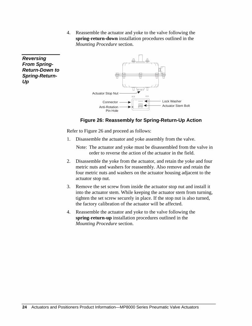
ConnectorActuator Stem BoltLock Washer
Actuator Stop Nut
Anti-RotationPin Hole
Figure 26: Reassembly for Spring-Return-Up Action
Refer to Figure 26 and proceed as follows:
1. Disassemble the actuator and yoke assembly from the valve.
Note: The actuator and yoke must be disassembled from the valve in order to reverse the action of the actuator in the field.
2. Disassemble the yoke from the actuator, and retain the yoke and four metric nuts and washers for reassembly. Also remove and retain the four metric nuts and washers on the actuator housing adjacent to the actuator stop nut.
3. Remove the set screw from inside the actuator stop nut and install it into the actuator stem. While keeping the actuator stem from turning, tighten the set screw securely in place. If the stop nut is also turned, the factory calibration of the actuator will be affected.
4. Reassemble the actuator and yoke to the valve following the spring-return-up installation procedures outlined in the Mounting Procedure section.
Reversing From Spring-Return-Down to Spring-Return-Up
Actuators and Positioners Product Information—MP8000 Series Pneumatic Valve Actuators 25
MP8000 Actuator Maintenance and Repair
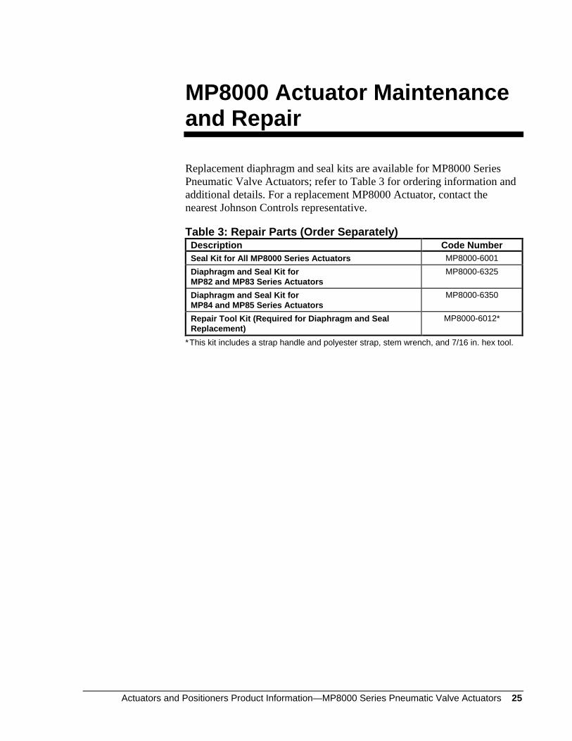
Replacement diaphragm and seal kits are available for MP8000 Series Pneumatic Valve Actuators; refer to Table 3 for ordering information and additional details. For a replacement MP8000 Actuator, contact the nearest Johnson Controls representative.
Table 3: Repair Parts (Order Separately) Description Code Number Seal Kit for All MP8000 Series Actuators MP8000-6001 Diaphragm and Seal Kit for MP82 and MP83 Series Actuators
MP8000-6325
Diaphragm and Seal Kit for MP84 and MP85 Series Actuators
MP8000-6350
Repair Tool Kit (Required for Diaphragm and Seal Replacement)
MP8000-6012*
* This kit includes a strap handle and polyester strap, stem wrench, and 7/16 in. hex tool.
26 Actuators and Positioners Product Information—MP8000 Series Pneumatic Valve Actuators
Notes
Actuators and Positioners Product Information—MP8000 Series Pneumatic Valve Actuators 27
Notes
28 Actuators and Positioners Product Information—MP8000 Series Pneumatic Valve Actuators
Notes
European Single Point of Contact: NA/SA Single Point of Contact: APAC Single Point of Contact: JOHNSON CONTROLS WESTENDHOF 3 45143 ESSEN GERMANY
JOHNSON CONTROLS 507 E MICHIGAN ST MILWAUKEE WI 53202 USA
JOHNSON CONTROLS C/O CONTROLS PRODUCT MANAGEMENT NO. 22 BLOCK D NEW DISTRICT WUXI JIANGSU PROVINCE 214142 CHINA
Controls Group FAN 977 507 E. Michigan Street Valve and Actuator Manual P.O. Box 423 Printed in U.S.A. Milwaukee, WI 53201 www.johnsoncontrols.com