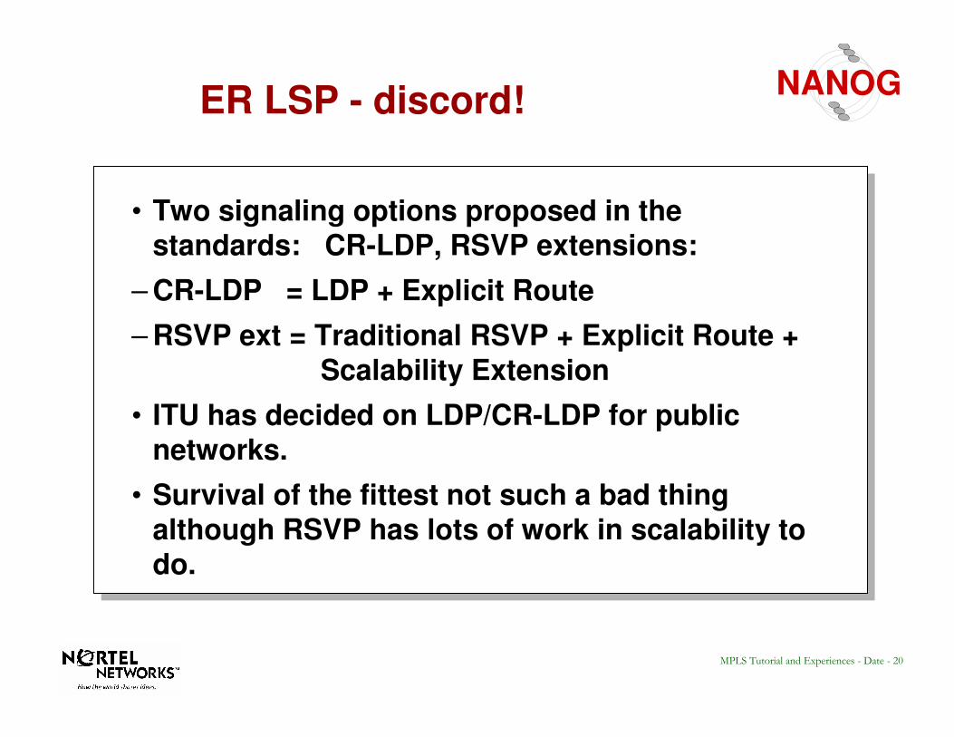
• ITU has decided on LDP/CR-LDP for public networks.
• Survival of the fittest not such a bad thing although RSVP has lots of work in scalability to do.
21MPLS Tutorial and Experiences - Date - 21
NANOGTutorial Outline
• Overview
•• Label EncapsulationsLabel Encapsulations• Label Distribution Protocols
• MPLS & ATM
• Constraint Based Routing with CR-LDP
• Operational Experiences with Similar Protocols
• Summary
22MPLS Tutorial and Experiences - Date - 22
NANOGLabel Encapsulation
ATM FR Ethernet PPP
MPLS Encapsulation is specified over various media types. Top labels may use existing format, lower label(s) use a new “shim” label format.
VPI VCI DLCI “Shim Label”
L2
Label
“Shim Label” …….
IP | PAYLOAD
23MPLS Tutorial and Experiences - Date - 23
NANOGMPLS Link Layers
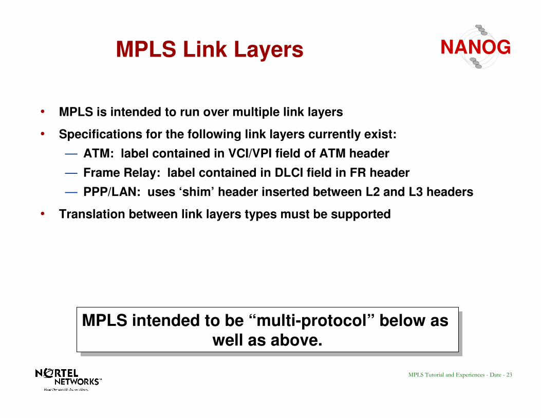
MPLS intended to be “multi-protocol” below as well as above.
MPLS intended to be “multi-protocol” below as well as above.
• MPLS is intended to run over multiple link layers
• Specifications for the following link layers currently exist:
— ATM: label contained in VCI/VPI field of ATM header
— Frame Relay: label contained in DLCI field in FR header
— PPP/LAN: uses ‘shim’ header inserted between L2 and L3 headers
• Translation between link layers types must be supported
24MPLS Tutorial and Experiences - Date - 24
NANOGMPLS Encapsulation - ATM
ATM LSR constrained by the cell format imposed by existing ATM standardsATM LSR constrained by the cell format imposed by existing ATM standards
VPI PT CLP HEC
5 Octets
ATM HeaderFormat VCI
AAL5 Trailer
•••Network Layer Header
and Packet (eg. IP)
1n
AAL 5 PDU Frame (nx48 bytes)
Generic Label Encap.(PPP/LAN format)
ATMSAR
ATM HeaderATM Payload • • •
• Top 1 or 2 labels are contained in the VPI/VCI fields of ATM header
- one in each or single label in combined field, negotiated by LDP• Further fields in stack are encoded with ‘shim’ header in PPP/LAN format
- must be at least one, with bottom label distinguished with ‘explicit NULL’
• TTL is carried in top label in stack, as a proxy for ATM header (that lacks TTL)
48 Bytes
48 Bytes
Label LabelOption 1
Option 2 Combined Label
Option 3 LabelATM VPI (Tunnel)
25MPLS Tutorial and Experiences - Date - 25
NANOGMPLS Encapsulation -Frame Relay
•••n 1
DLCIC/R
EA
DLCIFECN
BECN
DE
EA
Q.922Header
Generic Encap.(PPP/LAN Format) Layer 3 Header and Packet
DLCI Size = 10, 17, 23 Bits
• Current label value carried in DLCI field of Frame Relay header
• Can use either 2 or 4 octet Q.922 Address (10, 17, 23 bytes)
• Generic encapsulation contains n labels for stack of depth n- top label contains TTL (which FR header lacks), ‘explicit NULL’ label
value
26MPLS Tutorial and Experiences - Date - 26
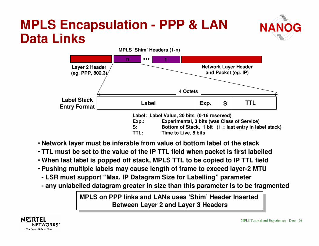
NANOGMPLS Encapsulation - PPP & LAN Data Links
Label Exp. S TTL
Label: Label Value, 20 bits (0-16 reserved)Exp.: Experimental, 3 bits (was Class of Service)S: Bottom of Stack, 1 bit (1 = last entry in label stack)TTL: Time to Live, 8 bits
Layer 2 Header(eg. PPP, 802.3)
•••Network Layer Header
and Packet (eg. IP)
4 Octets
MPLS ‘Shim’ Headers (1-n)
1n
• Network layer must be inferable from value of bottom label of the stack
• TTL must be set to the value of the IP TTL field when packet is first labelled
• When last label is popped off stack, MPLS TTL to be copied to IP TTL field
• Pushing multiple labels may cause length of frame to exceed layer-2 MTU
- LSR must support “Max. IP Datagram Size for Labelling” parameter
- any unlabelled datagram greater in size than this parameter is to be fragmented
MPLS on PPP links and LANs uses ‘Shim’ Header Inserted
Between Layer 2 and Layer 3 Headers
MPLS on PPP links and LANs uses ‘Shim’ Header Inserted
Between Layer 2 and Layer 3 Headers
Label StackEntry Format
27MPLS Tutorial and Experiences - Date - 27
NANOGTutorial Outline
• Overview
•• Label EncapsulationsLabel Encapsulations
• Label Distribution Protocols
• MPLS & ATM
• Constraint Based Routing with CR-LDP
• Operational Experiences with Similar Protocols
• Summary
28MPLS Tutorial and Experiences - Date - 28
NANOGLabel Distribution Protocols
• Overview of Hop-by-hop & Explicit
• Label Distribution Protocol (LDP)
• Constraint-based Routing LDP (CR-LDP)
• Extensions to RSVP
29MPLS Tutorial and Experiences - Date - 29
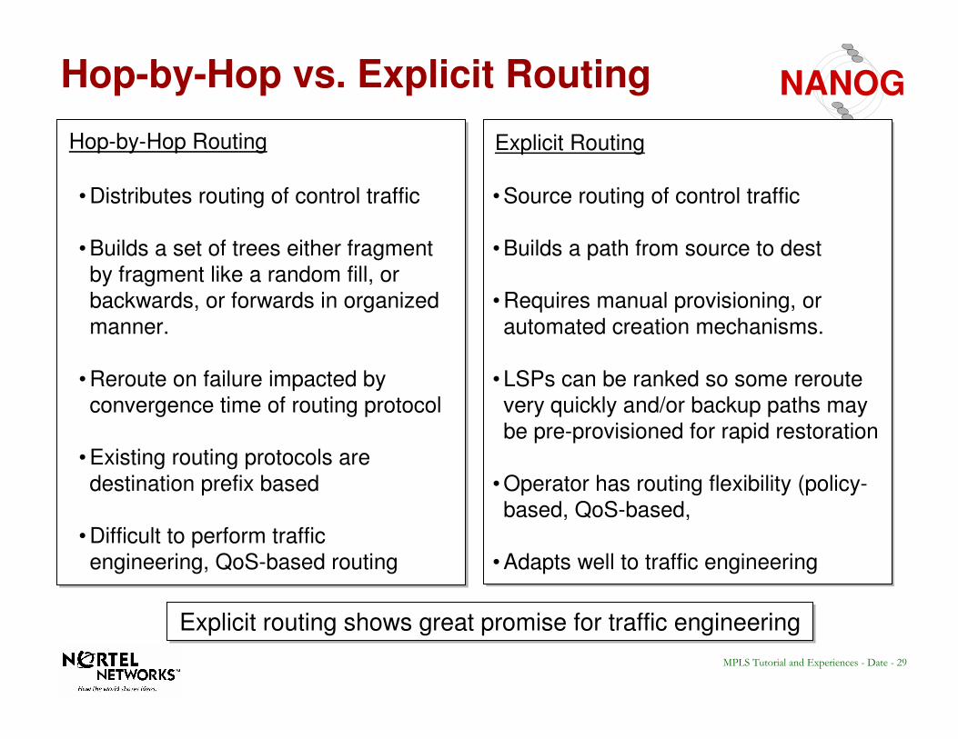
NANOGHop-by-Hop vs. Explicit Routing
Hop-by-Hop Routing Explicit Routing
• Source routing of control traffic
• Builds a path from source to dest
• Requires manual provisioning, or
automated creation mechanisms.
• LSPs can be ranked so some reroute
very quickly and/or backup paths may
be pre-provisioned for rapid restoration
• Operator has routing flexibility (policy-
based, QoS-based,
• Adapts well to traffic engineering
• Distributes routing of control traffic
• Builds a set of trees either fragment
by fragment like a random fill, or
backwards, or forwards in organized
manner.
• Reroute on failure impacted by
convergence time of routing protocol
• Existing routing protocols are
destination prefix based
• Difficult to perform traffic
engineering, QoS-based routing
Explicit routing shows great promise for traffic engineeringExplicit routing shows great promise for traffic engineering
30MPLS Tutorial and Experiences - Date - 30
NANOGExplicit Routing - MPLS vs. IP Source Routing• Connectionless nature of IP implies that routing is based on information in
each packet header.
• Source routing is possible, but path must be contained in each IP header.
• Lengthy paths increase size of IP header, make it variable size, increase overhead.
• Some gigabit routers require ‘slow path’ option-based routing of IP packets.
• Source routing has not been widely adopted in IP and is seen as impractical.
• Some network operators may filter source routed packets for security reasons.
• MPLS enables the use of source routing by its connection-oriented capabilities.
- paths can be explicitly set up through the network
- the ‘label’ can now represent the explicitly routed path
• Loose and strict source routing can be supported.
31MPLS Tutorial and Experiences - Date - 31
NANOGLabel Distribution Protocols
• Overview of Hop-by-hop & Explicit
• Label Distribution Protocol (LDP)
• Constraint-based Routing LDP (CR-LDP)
• Extensions to RSVP
• Extensions to BGP
32MPLS Tutorial and Experiences - Date - 32
NANOGLabel Distribution Protocol (LDP) -Purpose
Label distribution ensures that adjacent routers have
a common view of FEC <-> label bindings
Routing Table:
Addr-prefix Next Hop
47.0.0.0/8 LSR2
Routing Table:
Addr-prefix Next Hop
47.0.0.0/8 LSR2
LSR1 LSR2 LSR3
IP Packet 47.80.55.3
Routing Table:
Addr-prefix Next Hop
47.0.0.0/8 LSR3
Routing Table:
Addr-prefix Next Hop
47.0.0.0/8 LSR3
For 47.0.0.0/8
use label ‘17’Label Information Base:
Label-In FEC Label-Out
17 47.0.0.0/8 XX
Label Information Base:
Label-In FEC Label-Out
17 47.0.0.0/8 XX
Label Information Base:
Label-In FEC Label-Out
XX 47.0.0.0/8 17
Label Information Base:
Label-In FEC Label-Out
XX 47.0.0.0/8 17
Step 1: LSR creates bindingbetween FEC and label value
Step 2: LSR communicatesbinding to adjacent LSR
Step 3: LSR inserts labelvalue into forwarding base
Common understanding of which FEC the label is referring to!
Label distribution can either piggyback on top of an existing routing protocol,
or a dedicated label distribution protocol (LDP) can be created.
Label distribution can either piggyback on top of an existing routing protocol,
or a dedicated label distribution protocol (LDP) can be created.
33MPLS Tutorial and Experiences - Date - 33
NANOGLabel Distribution - Methods
LSR1 LSR2
Label Distribution can take place using one of two possible methodsLabel Distribution can take place using one of two possible methods
Downstream Unsolicited Label Distribution
Label-FEC Binding
• LSR2 and LSR1 are said to have an “LDP adjacency” (LSR2 being the downstream LSR)
• LSR2 discovers a ‘next hop’ for a particular FEC
• LSR2 generates a label for the FEC and communicates the binding to LSR1
• LSR1 inserts the binding into its forwarding tables
• If LSR2 is the next hop for the FEC, LSR1 can use that label knowing that its meaning is understood
LSR1 LSR2
Downstream-on-Demand Label Distribution
Label-FEC Binding
• LSR1 recognizes LSR2 as its next-hop for an FEC
• A request is made to LSR2 for a binding between the FEC and a label
• If LSR2 recognizes the FEC and has a next hop for it, it creates a binding and replies to LSR1
• Both LSRs then have a common understanding
Request for Binding
Both methods are supported, even in the same network at the same time
For any single adjacency, LDP negotiation must agree on a common method
34MPLS Tutorial and Experiences - Date - 34
NANOG
#963
#14
#99
#311
#311
#311
Downstream Mode Making SPF Tree Copy In H/W
#462
D
#311
D
#963D
#14 D
#99
D
#216
D
#612 D
#5 D
35MPLS Tutorial and Experiences - Date - 35
NANOG
#963
#14
#99
#311
#311
#311
Downstream On Demand Making SPF Tree Copy In H/W
#462
D
#311
D
#963D#14 D
#99
D
#216
D
#612 D
#5 D
D?
D? D?
D?D?
D?
D?
D?
36MPLS Tutorial and Experiences - Date - 36
NANOGDistribution Control: Ordered v. Independent
Independent LSP ControlIndependent LSP Control Ordered LSP ControlOrdered LSP Control
Next Hop(for FEC)
Outgoing
Label
IncomingLabel
MPLS path forms as associationsare made between FEC next-hopsand incoming and outgoing labels
• Each LSR makes independent decision on when to generate labels and communicate them to upstream
peers
• Communicate label-FEC binding to peers once
next-hop has been recognized
• LSP is formed as incoming and outgoing labels are
spliced together
• Label-FEC binding is communicated to peers if:- LSR is the ‘egress’ LSR to particular FEC
- label binding has been received from
upstream LSR
• LSP formation ‘flows’ from egress to ingress
DefinitionDefinition
ComparisonComparison • Labels can be exchanged with less delay
• Does not depend on availability of egress node
• Granularity may not be consistent across the nodes at the start
• May require separate loop detection/mitigation
method
• Requires more delay before packets can be
forwarded along the LSP
• Depends on availability of egress node
• Mechanism for consistent granularity and freedom
from loops
• Used for explicit routing and multicast
Both methods are supported in the standard and can be fully interoperable
37MPLS Tutorial and Experiences - Date - 37
NANOG
#963
#14
#99
#311
#311
#311
INDEPENDENT MODE
#462
D
#311
D
#963D
#14 D
#99
D
#216
D
#612 D
#5 D
38MPLS Tutorial and Experiences - Date - 38
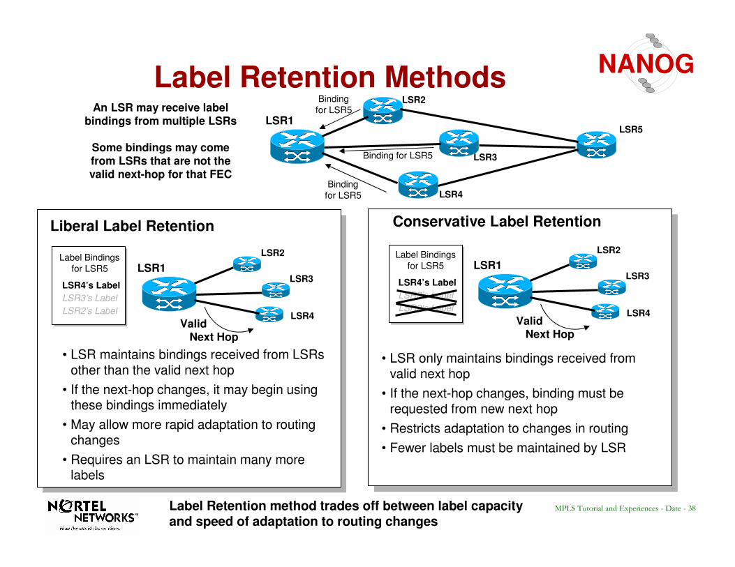
NANOGLabel Retention Methods
LSR1
LSR2
LSR3
LSR4
LSR5
Binding
for LSR5
Binding for LSR5
Binding
for LSR5An LSR may receive labelbindings from multiple LSRs
Some bindings may comefrom LSRs that are not thevalid next-hop for that FEC
Liberal Label Retention Conservative Label Retention
LSR1
LSR2
LSR3
LSR4
Label Bindings
for LSR5
ValidNext Hop
LSR4’s Label
LSR3’s Label
LSR2’s Label
LSR1
LSR2
LSR3
LSR4
Label Bindings
for LSR5
ValidNext Hop
LSR4’s Label
LSR3’s Label
LSR2’s Label
• LSR maintains bindings received from LSRsother than the valid next hop
• If the next-hop changes, it may begin using these bindings immediately
• May allow more rapid adaptation to routing changes
• Requires an LSR to maintain many more labels
• LSR only maintains bindings received from valid next hop
• If the next-hop changes, binding must be requested from new next hop
• Restricts adaptation to changes in routing
• Fewer labels must be maintained by LSR
Label Retention method trades off between label capacity and speed of adaptation to routing changes
39MPLS Tutorial and Experiences - Date - 39
NANOGLIBERAL RETENTION MODE
#462
D
#311
D
#963D
#14 D
#99
D
#216
D
#612 D
#5 D
#422
D
#622 D
These labels are kept in case they are needed after a failure.
40MPLS Tutorial and Experiences - Date - 40
NANOGCONSERVATIVE RETENTION MODE
#462
D
#311
D
#963D
#14 D
#99
D
#216
D
#612 D
#5 D
#422
D
#622 D
These labels are
released the moment they are received.
41MPLS Tutorial and Experiences - Date - 41
NANOGLDP - STATUS
•Last Call Ended going to IESG for RFC
also ITU SG13 has adopted for IP on ATM.
•Multi Vendor interoperability
demonstrated for Downstream on demand mode on OC-3/ATM by
(Nortel Networks, Ericson, Cisco, H&J, Ficom … 7 vendors) at Atlanta Interop/99
•Source code for these PDUs publicly available: www.NortelNetworks.com/mpls
•LINUX implementation using above code publicly available.
42MPLS Tutorial and Experiences - Date - 42
NANOGLabel Distribution Protocols
• Overview of Hop-by-hop & Explicit
• Label Distribution Protocol (LDP)
• Constraint-based Routing LDP (CR-LDP)
• Extensions to RSVP
43MPLS Tutorial and Experiences - Date - 43
NANOGConstraint-based LSP Setup using LDP
• Uses LDP Messages (request, map, notify)
• Shares TCP/IP connection with LDP
• Can coexist with vanilla LDP and inter-work with it, or can exist as an entity on its own
• Introduces additional data to the vanilla LDP messages to signal ER, and other “Constraints”
44MPLS Tutorial and Experiences - Date - 44
NANOGER-LSP Setup using CR-LDP
LSR B LSR C LER DLER A
ER Label
Switched PathIngress Egress
4. Label mapping
message originates.
3. Request message
terminates.
2. Request message processed
and next node determined.
Path list modified to <C,D>
1. Label Request message. It
contains ER path < B,C,D>
5. LSR C receives label to
use for sending data to LER
D. Label table updated
6. When LER A
receives label mapping,
the ER established.
45MPLS Tutorial and Experiences - Date - 45
NANOG
#216
#14
#612
#5
#311
#462
- It is possible to take a vanilla LDP label request let it flow vanilla to the edge of the core, insert
an ER hop list at the core boundary at which
point it is CR-LDP to the far side of the core.
A
B
C
LDP CR-LDP
#99
INSERT ER{A,B,C}
LDP/CR-LDP INTERWORKING
46MPLS Tutorial and Experiences - Date - 46
NANOGBasic LDP Message additions
• LSPID: A unique tunnel identifier within an MPLS network.
• ER: An explicit route, normally a list of IPV4 addresses to follow (source route) the label request message.
• Resource Class (Color): to constrain the route to only links of this Color. Basically a 32 bit mask used for constraint based computations.
• Traffic Parameters: similar to ATM call setup, which specify treatment and reserve resources.
47MPLS Tutorial and Experiences - Date - 47
NANOG
Length
Peak Data Rate (PDR)
Peak Burst Size (PBS)
Committed Data Rate (CDR)
Committed Burst Size (CBS)
Excess Burst Size (EBS)
Traf. Param. TLV U F
Reserved Weight Frequency Flags
Flags control “negotiability” of
parameters
Frequency constrains the variable
delay that may be introduced
Weight of the CRLSP in the
“relative share”
Peak rate (PDR+PBS) maximum rate at which traffic should be sent
to the CRLSP
Committed rate (CDR+CBS) the rate that the MPLS domain commits to be available to the
CRLSP
Excess Burst Size (EBS) to measure the extent by which the traffic sent on a CRLSP exceeds the committed rate
32 bit fields are short IEEE floating point
numbers
Any parameter may be used or not used by
selecting appropriate values
CR-LDP Traffic Parameters
48MPLS Tutorial and Experiences - Date - 48
NANOGCRLSP characteristics not edge functions
• The approach is like diff-serv’s separation of PHB from Edge
• The parameters describe the “path behavior” of the CRLSP, i.e. the CRLSP’s characteristics
• Dropping behavior is not signaled
— Dropping may be controlled by DS packet markings
• CRLSP characteristics may be combined with edge functions (which are undefined in CRLDP) to create services
— Edge functions can perform packet marking
— Example services are in an appendix
49MPLS Tutorial and Experiences - Date - 49
NANOGPeak rate
• The maximum rate at which traffic should be sent to the CRLSP
• Defined by a token bucket with parameters
— Peak data rate (PDR)
— Peak burst size (PBS)
• Useful for resource allocation
• If a network uses the peak rate for resource allocation then its edge function should regulate the peak rate
• May be unused by setting PDR or PBS or both to positive infinity
50MPLS Tutorial and Experiences - Date - 50
NANOGCommitted rate
• The rate that the MPLS domain commits to be available to the CRLSP
• Defined by a token bucket with parameters
— Committed data rate (CDR)
— Committed burst size (CBS)
• Committed rate is the bandwidth that should be reserved for the CRLSP
• CDR = 0 makes sense; CDR = +∞∞∞∞ less so
• CBS describes the burstiness with which traffic may be sent to the CRLSP
51MPLS Tutorial and Experiences - Date - 51
NANOGExcess burst size
• Measure the extent by which the traffic sent on a CRLSP exceeds the committed rate
• Defined as an additional limit on the committed rate’s token bucket
• Can be useful for resource reservation
• If a network uses the excess burst size for resource allocation then its edge function should regulate the parameter and perhaps mark or drop packets
• EBS = 0 and EBS = +∞∞∞∞ both make sense
52MPLS Tutorial and Experiences - Date - 52
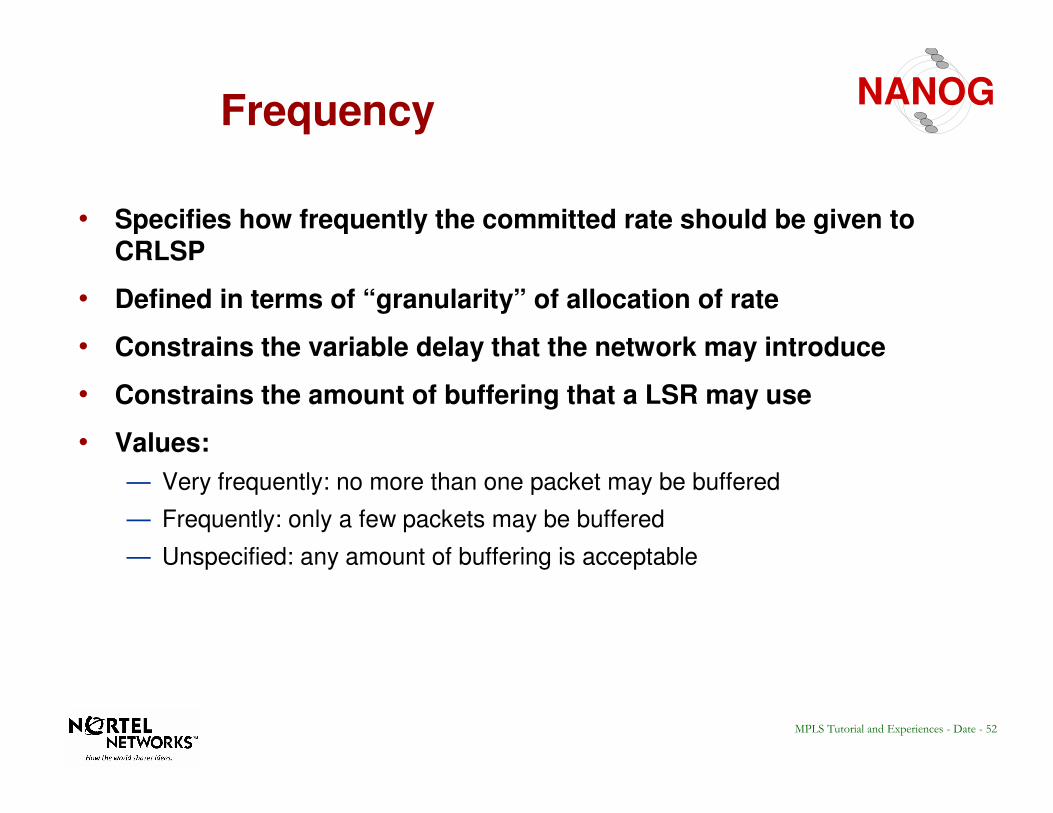
NANOGFrequency
• Specifies how frequently the committed rate should be given to CRLSP
• Defined in terms of “granularity” of allocation of rate
• Constrains the variable delay that the network may introduce
• Constrains the amount of buffering that a LSR may use
• Values:
— Very frequently: no more than one packet may be buffered
— Frequently: only a few packets may be buffered
— Unspecified: any amount of buffering is acceptable
53MPLS Tutorial and Experiences - Date - 53
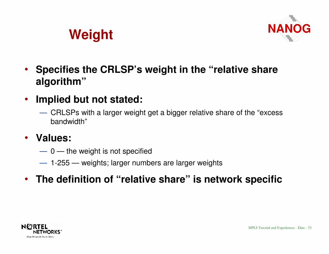
NANOGWeight
• Specifies the CRLSP’s weight in the “relative share algorithm”
• Implied but not stated:
— CRLSPs with a larger weight get a bigger relative share of the “excess
bandwidth”
• Values:
— 0 — the weight is not specified
— 1-255 — weights; larger numbers are larger weights
• The definition of “relative share” is network specific
54MPLS Tutorial and Experiences - Date - 54
NANOGNegotiation flags
F1F2F3F4F5F6Res
PD
R N
eg
otiation F
lag
PB
S N
egotiatio
n F
lag
CD
R N
egotiation F
lag
CB
S N
egotiation F
lag
EB
S N
egotiatio
n F
lag
Weig
ht
Neg
otiation F
lag
If a parameter is flagged as negotiable then LSRs may replace the parameter value with a smaller value in the label request message. LSRs discover the negotiated values in the label mapping message.
Label request - possible downward negotiation
Label mapping -no negotiation
55MPLS Tutorial and Experiences - Date - 55
NANOGCR-LDP PREEMPTION
A CR-LSP carries an LSP priority. This
priority can be used to allow new LSPs to bump existing LSPs of lower priority in order to steal their resources.
This is especially useful during times of failure and allows you to rank the LSPssuch that the most important obtain resources before less important LSPs.
These are called the setupPriority and a holdingPriority and 8 levels are provided.
56MPLS Tutorial and Experiences - Date - 56
NANOGCR-LDP PREEMPTION
When an LSP is established its
setupPriority is compared with the holdingPriority of existing LSPs, any with lower holdingPriority may be bumped to obtain their resources.
This process may continue in a domino fashion until the lowest holdingPriorityLSPs either clear or are on the worst
routes.
57MPLS Tutorial and Experiences - Date - 57
NANOG
#216
#14
#462
#972A
B
C
Route={A,B,C}
PREEMPTION A.K.A. BUMPING
58MPLS Tutorial and Experiences - Date - 58
NANOGTOPOLOGY DB FOR BUMPING
LOW PRI
HIGH PRI Topology Database sees 8 levels of bandwidth, depending on the setup priority of the LSP, a subset of that bandwidth is seen as available.
The highest priority sees all bandwidth used and free at
levels lower that it, etc. to the lowest priority which only sees unused bandwidth.
ATM Label Switching is the combination of L3 routing and L2 ATM switchingATM Label Switching is the combination of L3 routing and L2 ATM switching
67MPLS Tutorial and Experiences - Date - 67
NANOG2. MPLS Over ATM
MPLS
ATM Network
MPLS
L
S
R
L
S
R
VCVP
Two Models
Internet Draft:�VCID notification over ATM Link
68MPLS Tutorial and Experiences - Date - 68
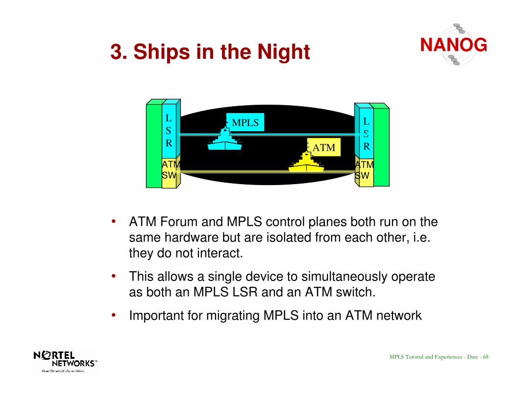
NANOG3. Ships in the Night
• ATM Forum and MPLS control planes both run on the same hardware but are isolated from each other, i.e. they do not interact.
• This allows a single device to simultaneously operate as both an MPLS LSR and an ATM switch.
• Important for migrating MPLS into an ATM network
ATMSW
L
S
R ATM
MPLS
ATMSW
L
S
R
69MPLS Tutorial and Experiences - Date - 69
NANOGShips in the night Requirements
• Resource Management
—VPI.VCI Space Partitioning
—Traffic management
–Bandwidth Reservation
–Admission Control
–Queuing & Scheduling
–Shaping/Policing
—Processing Capacity
70MPLS Tutorial and Experiences - Date - 70
NANOGBandwidth Management
•• Bandwidth GuaranteesBandwidth Guarantees
•• FlexibilityFlexibility
A.A. Full SharingFull Sharing
Po
rt C
ap
acity
Po
rt C
ap
acity
Pool 1 Pool 1 ••MPLSMPLS••ATMATM
MPLSMPLS
ATMATM
AvailableAvailable
B. Protocol PartitionB. Protocol Partition
Pool 2 Pool 2 ••50%50%••rtrt--VBRVBR
Pool 1 Pool 1 ••50%50%••ATMATM
MPLSMPLS
ATMATM
AvailableAvailable
AvailableAvailable
C. Service PartitionC. Service Partition
Pool 2 Pool 2 ••50%50%••nrtnrt--VBRVBR••COS1COS1
Pool 1 Pool 1 ••50%50%••rtrt--VBRVBR••COS2COS2
MPLSMPLS
ATMATM
AvailableAvailable
MPLSMPLS
ATMATM
AvailableAvailable
71MPLS Tutorial and Experiences - Date - 71
NANOGATM Merge
• Multipoint-to-point capability
• Motivation
—Stream Merge to achieve scalability in MPLS:
– O(n) VCs with Merge as opposed to O(n2) for full mesh
– less labels required
—Reduce number of receive VCs on terminals
• Alternatives
—Frame-based VC Merge
—Cell-based VP Merge
72MPLS Tutorial and Experiences - Date - 72
NANOGStream Merge
111
2 2 2
3 3
111
2 2 2
3 3
Input cell streams
Input cell streams
in out
1
2
3
7
6
9
1
2
3
7
7
7
in out
Non-VC merging (Nin--Nout)
VC merging (Nin-1out)
7 7 7 7 7 777
6 7 9 6 7 79 6
7 7 7 7 7 77
No Cell Interleaving
7
AAL5 Cell Interleaving Problem
73MPLS Tutorial and Experiences - Date - 73
NANOGVC-Merge: Output Module
Merge
Reassembly buffers
Output buffer
74MPLS Tutorial and Experiences - Date - 74
NANOGVP-Merge
VPI=3
VPI=2
VCI=1
VPI=1
VCI=2
VCI=3
VCI=1
VCI=2
VCI=3
–merge multiple VPs into one VP
–use separate VCIs within VPs to distinguish frames
–less efficient use of VPI/VCI space, needs support of SVP
No Cell Interleaving Problem
Since VCI is unique
Option 1: Dynamic VCI Mapping
Option 2: Root
Assigned VCI
75MPLS Tutorial and Experiences - Date - 75
NANOGTutorial Outline
• Overview
• Label Encapsulations
• Label Distribution Protocols
• MPLS & ATM
• Constraint Based Routing with CR-LDP
• Operational Experiences with Similar Protocols
•• SummarySummary
76MPLS Tutorial and Experiences - Date - 76
NANOG
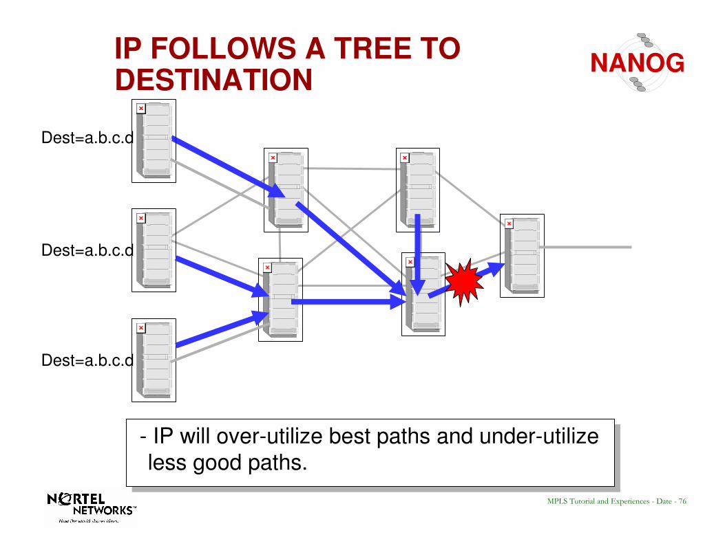
- IP will over-utilize best paths and under-utilize
less good paths.
Dest=a.b.c.d
Dest=a.b.c.d
Dest=a.b.c.d
IP FOLLOWS A TREE TO DESTINATION
77MPLS Tutorial and Experiences - Date - 77
NANOG
#216
#14
#612
#5 #99 #311
#963
#462
- Ultra fast, simple forwarding a.k.a switching
- Follows same route as normal IP datapath
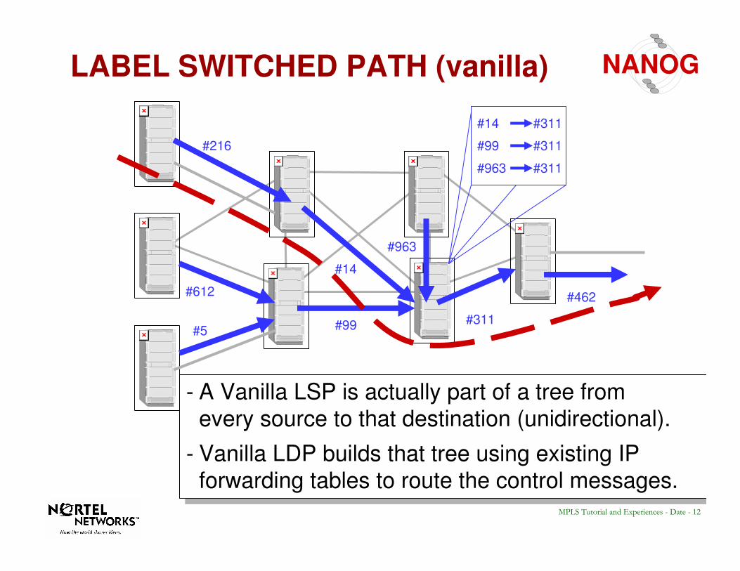
- So like IP, LDP will over-utilize best paths and under-utilize less good paths.
HOP-BY-HOP(A.K.A Vanilla) LDP
78MPLS Tutorial and Experiences - Date - 78
NANOG
Two types of Label Switched Paths:
• Hop by hop (“Vanilla” LDP)
• Explicit Routing (LDP+”ER”)
#18
#427
#819
#216
#14
#612
#5 #99 #311
#963
#462
#77
Label Switched Path (Two Types)
79MPLS Tutorial and Experiences - Date - 79
NANOG
• CR = “Constraint” based “Routing”
• eg: USE: (links with sufficient resources AND
(links of type “someColor”) AND
(links that have delay less than 200 ms)
&&
=
CR-LDP
80MPLS Tutorial and Experiences - Date - 80
NANOG
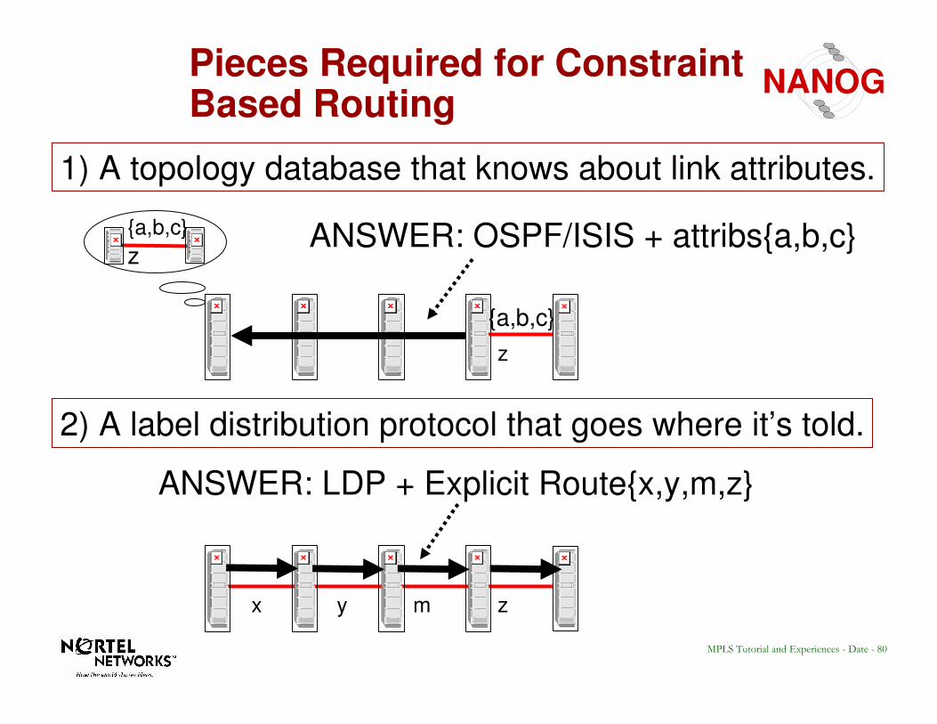
1) A topology database that knows about link attributes.
2) A label distribution protocol that goes where it’s told.
z
{a,b,c}
ANSWER: OSPF/ISIS + attribs{a,b,c}
zmyx
ANSWER: LDP + Explicit Route{x,y,m,z}
z
{a,b,c}
Pieces Required for Constraint Based Routing
81MPLS Tutorial and Experiences - Date - 81
NANOGTraffic Engineering
A
B C
D
Traffic engineering is the process of mapping traffic demand onto a networkTraffic engineering is the process of mapping traffic demand onto a network
Demand
Network
Topology
Purpose of traffic engineering:
• Maximize utilization of links and nodes throughout the network• Engineer links to achieve required delay, grade-of-service
• Spread the network traffic across network links, minimize impact of single failure• Ensure available spare link capacity for re-routing traffic on failure
• Meet policy requirements imposed by the network operator
Traffic engineering key to optimizing cost/performance
82MPLS Tutorial and Experiences - Date - 82
NANOGMPLS Traffic Engineering Methods
• MPLS can use the source routing capability to steer traffic on desired path
• Operator may manually configure these in each LSR along the desired path- analogous to setting up PVCs in ATM switches
• Ingress LSR may be configured with the path, RSVP used to set up LSP
- some vendors have extended RSVP for MPLS path set-up
• Ingress LSR may be configured with the path, LDP used to set up LSP- many vendors believe RSVP not suited
• Ingress LSR may be configured with one or more LSRs along the desired path, hop-by-hop routing may be used to set up the rest of the path
- a.k.a loose source routing, less configuration required
• If desired for control, route discovered by hop-by-hop routing can be frozen
- a.k.a “route pinning”
• In the future, constraint-based routing will offload traffic engineering tasks from the operator to the network itself
83MPLS Tutorial and Experiences - Date - 83
NANOG
• Overview
• Label Encapsulations
• Label Distribution Protocols
• MPLS & ATM
• Constraint Based Routing with CR-LDP
• Operational Experiences with Similar Protocols.
•• SummarySummary
Tutorial Outline
84MPLS Tutorial and Experiences - Date - 84
NANOG
• Feedback required to get acceptable blocking and improved rerouting times/accuracy and bigger flat networks.
• Load Spreading requires Preemption be supported together.
• Optimization is required and must be done as a hot swap.
• Region to Region routing is possible with local segment optimization/rerouting.
OPERATIONAL EXPERIENCESWITH SIMILAR PROTOCOLS (PORS)
85MPLS Tutorial and Experiences - Date - 85
NANOGRESOURCE FEEDBACK
43
2 5
1 6
43
2 5
1 6
TOPOLOGY D.B
10M
5M
10M
10M
5M10M
5M
10M
5M10M
5M
10M
5M10M
10M 10M
Feedback is used to piggy back resource information on any control
messages such as setup, release, notification. This reduces the time required for the database to synchronize and allows rerouting BEFORE the floods arrive. This decreases blocking time, reduces flood intervals and allows larger flat topologies.
86MPLS Tutorial and Experiences - Date - 86
NANOGLOAD SPREADING REQUIRES PREMPTION
43
2 5
1 6
If you spread load you will leave lots of small bandwidth holes which individually may not be enough to satisfy new requests but taken together
would be able. Therefore if you do spread load you need a way to move that load around to free up larger holes of bandwidth, I.e. you need preemption if you do spreading.
10M LSP
10M LSP
10M free
10M free
20M LSP?
10M LSP
20M LSP
0M free
0M free
87MPLS Tutorial and Experiences - Date - 87
NANOGHOT OPTIMIZATION IS REQUIRED
43
2 5
1 6
Just as a connectionless network will react to the discovery of a better route by using it, so should a path oriented routing system. An MPLS LSP must detect the presence of a better route and switch to it with the minimum of loss. This means it must do it hot, I.e. establish the new LSP, then move traffic to it.
It must also do this without double booking bandwidth on common sub segments.
88MPLS Tutorial and Experiences - Date - 88
NANOGREGION TO REGION WITH LOCAL OPTIMIZATIONS/REPAIR
It is possible to do optimizations and repair within a flat topology region. This means that the gateway remains fixed but that segments between the gateways that cross an AS can move around independently of each other.
43
2 5
1 6
DC
B E
A F
89MPLS Tutorial and Experiences - Date - 89
NANOG
• Overview
• Label Encapsulations
• Label Distribution Protocols
• MPLS & ATM
• Constraint Based Routing with CR-LDP
• Operational Experiences with Similar Protocols.
•• SummarySummary
Tutorial Outline
90MPLS Tutorial and Experiences - Date - 90
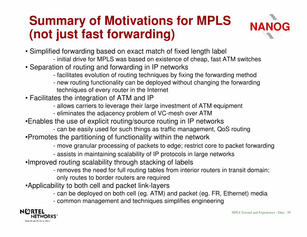
NANOGSummary of Motivations for MPLS (not just fast forwarding)
• Simplified forwarding based on exact match of fixed length label- initial drive for MPLS was based on existence of cheap, fast ATM switches
• Separation of routing and forwarding in IP networks- facilitates evolution of routing techniques by fixing the forwarding method
- new routing functionality can be deployed without changing the forwarding
techniques of every router in the Internet
• Facilitates the integration of ATM and IP- allows carriers to leverage their large investment of ATM equipment
- eliminates the adjacency problem of VC-mesh over ATM
•Enables the use of explicit routing/source routing in IP networks- can be easily used for such things as traffic management, QoS routing
•Promotes the partitioning of functionality within the network
- move granular processing of packets to edge; restrict core to packet forwarding
- assists in maintaining scalability of IP protocols in large networks
•Improved routing scalability through stacking of labels- removes the need for full routing tables from interior routers in transit domain;
only routes to border routers are required
•Applicability to both cell and packet link-layers- can be deployed on both cell (eg. ATM) and packet (eg. FR, Ethernet) media
- common management and techniques simplifies engineering
91MPLS Tutorial and Experiences - Date - 91
NANOGIP and ATM Integration
IP over ATM VCsIP over ATM VCs
• ATM cloud invisible to Layer 3 Routing
• Full mesh of VCs within ATM cloud
• Many adjacencies between edge routers
• Topology change generates many route updates
• Routing algorithm made more complex
• ATM network visible to Layer 3 Routing
• Singe adjacency possible with edge router
• Hierachical network design possible
• Reduces route update traffic and power needed to process them
IP over MPLSIP over MPLS
MPLS eliminates the “n-squared” problem of IP over ATM VCsMPLS eliminates the “n-squared” problem of IP over ATM VCs
92MPLS Tutorial and Experiences - Date - 92
NANOGMPLS: Scalability Through Hierarchy
BR1
BR2
BR3
BR4
TR1 TR2
TR3TR4
AS1AS2 AS3
• Border routers BR1-4 run an EGP, providing inter-domain routing
• Interior transit routers TR1-4 run an IGP, providing intra-domain routing
• Normal layer 3 forwarding requires interior routers to carry full routing tables
- transit router must be able to identify the correct destination ASBR (BR1-4)
• Carrying full routing tables in all routers limits scalability of interior routing