Oil Boiler Wiring & Application GuideU.S. Boiler Company
10/14/132
Table of Contents1.0 Introduction ........................................................................................................................... 3
2.0 IQ Oil Boiler Control System .........................................................................................................................................4-6 2.1 Single Zone Heating ............................................................................................................................................... 7 2.2 Single Zone Heating, Power Stealing Thermostat ................................................................................................... 8 2.3 Single Zone Heating, Indirect Water Heater (IWH) w/TPI Control ........................................................................... 9 2.4 Single Zone Heating, IWH w/Aquastat Control ..................................................................................................... 10 2.5 Two Zone Heating w/Additional 24V-AC Relay ..................................................................................................... 11 2.6 Two Zone Heating, One Low Voltage & One Line Voltage Thermostat .................................................................. 12 2.7 Zone Valves Heating ............................................................................................................................................. 13 2.8 Zone Valves Heating, IWH w/TPI Control, 2 Circulators ....................................................................................... 14 2.9 Zone Valves Heating, IWH w/Aquastat Control, 2 Circulators ............................................................................... 15 2.10 Zone Valves Heating, IWH w/TPI Control, 1 Circulator ......................................................................................... 16 2.11 Zone Valves Heating, IWH w/Aquastat Control, 1 Circulator ................................................................................. 17 2.12 Zone Valve Control Heating, IWH w/TPI Control, 2 Circulators ............................................................................. 18 2.13 Zone Valve Control Heating, IWH w/Aquastat Control, 2 Circulators .................................................................... 19 2.14 Zone Valve Control Heating, IWH w/TPI Control, 1 Circulator .............................................................................. 20 2.15 Zone Valve Control Heating, IWH w/Aquastat Control, 1 Circulator ...................................................................... 21 2.16 Zone Switching Relay Heating .............................................................................................................................. 22 2.17 Zone Switching Relay Heating, IWH w/TPI Control .............................................................................................. 23 2.18 Zone Switching Relay Heating, IWH w/Aquastat Control ...................................................................................... 24 2.19 Zone Switching Relay Heating, IWH w/Aquastat Control ...................................................................................... 25
3.0 IQ Oil Boiler Control System, Outdoor Reset Card ..................................................................................................26-27 3.1 Single Zone Heating ............................................................................................................................................. 28 3.2 Single Zone Heating, Power Stealing Thermostat ................................................................................................. 29 3.3 Single Zone Heating, IWH w/TPI Control .............................................................................................................. 30 3.4 Single Zone Heating, IWH w/Aquastat Control ..................................................................................................... 31 3.5 Zone Valves Heating, IWH w/TPI Control, 2 Circulators ....................................................................................... 32 3.6 Zone Valves Heating, IWH w/Aquastat Control, 2 Circulators ............................................................................... 33 3.7 Zone Valves Heating, IWH w/TPI Control, 1 Circulator, No Priority....................................................................... 34 3.8 Zone Valve Heating, IWH w/Aquastat Control, 1 Circulator, No Priority ................................................................ 35 3.9 Zone Valve Control Heating, IWH w/TPI Control, 2 Circulators ............................................................................. 36 3.10 Zone Valve Control Heating, IWH w/Aquastat Control, 2 Circulators .................................................................... 37 3.11 Zone Valve Control Heating and IWH w/TPI Control, 1 Circulator ........................................................................ 38 3.12 Zone Valve Control Heating and IWH w/Aquastat Control, 1 Circulator ................................................................ 39 3.13 Zone Switching Relay, IWH w/TPI Control ............................................................................................................ 40 3.14 Zone Switching Relay, IWH w/Aquastat Control ................................................................................................... 41
Oil Boiler Wiring & Application GuideU.S. Boiler Company
10/14/133
1.0 Introduction The IQ Control System included on the MPO-IQ boiler contains features and capabilities which can improve heating system operation, reduce fuel costs, improve comfort, and efficiency. By including unique capabilities, Burnham brand boilers can do more, with less field wiring, and fewer aftermarket controls and components – improving the operation of both new and replacement boiler installations.
These application drawings include detailed wiring diagrams, and set-up details, allowing installers to fully utilize the capability and versatility of the control system. These applications can save installers time and money on just about any heating system – whether it’s a new installation, or replacing an older, less efficient boiler.
Notice:While this manual contains wiring diagrams and set-up details, the Installation Operating and Service Instruction’s provided with each Burnham brand boiler must be followed.
Notice:Install wiring and electrically ground boiler in accordance with requirements of the authority having jurisdiction, or in absence of such requirements the National Electrical Code, ANSI/NFPA 70, and/or the CSA C22.1 Electric Code.
Using this Guide
Line Voltage AbbreviationsL1 – 120Vac Hot – Black L2 – 120Vac Neutral - White OCP IQ Option PanelGround - Green TPI Alliance IWH control IQ (Gas Boiler System) Combination of IHC and OCP on the boiler “T-T” Thermostat connection terminals
Low Voltage Polarity Important Red 24 Vac HotWhite (Grey) 24Vac Ground
Polarity Not ImportantBlue wires
Oil Boiler Wiring & Application GuideU.S. Boiler Company
10/14/134
2.0 IQ Oil Boiler Control SystemThe MPO-IQ features the IQ Oil Boiler Control system, which greatly simplifies installation and set-up in both existing and new heating systems. This control system contains many unique features and capabilities that save the installer time and take the mystery out of controls by providing simple, clear information about settings, status, and diagnostics on an LED display on the boiler. The IQ Oil Boiler Control System consists of the following components:
IQ Option Cards are snap-in control modules which attach to the Option Panel, and contain various control upgrades, such as Auxiliary High Temperature Limit, Low Water Cut-Off protection, and Outdoor Air Reset. There’s an IQ Option Card for each feature. Option Cards simply plug into the Option Panel, and feature a one or two wire connection to a sensor.
The IQ Option Panel is a separate control panel that accepts IQ Option Cards for added efficiency and safety. IQ Option Cards snap into any one of the three Slots in the Option Panel, and are instantly recognized when the IQ System is powered up. A separate LED display provides setting, status, & diagnostic info for each of the IQ Option Cards, greatly simplifying the set-up and operation of the control. IQ Option Cards are cost effective, they save time, and they are functionally superior to stand alone Limits, LWCO’s and Outdoor Reset controls.
IQ Oil Boiler Control This control may look like a normal Aquastat, but it does things no other Aquastat can do. Features like Circulator Pre Purge, Circulator Post Purge, and built-in control for a second (heating or DHW) zone can be selected and adjusted to improve comfort and efficiency in many heating systems – while simplifying installation. The IQ Oil Boiler Control is factory mounted and wired, saving the installer time, and reducing the potential for errors in the field.
Oil Boiler Wiring & Application GuideU.S. Boiler Company
10/14/135
Parameter Range Parameter Description Default
HL 140°F – 240°F High Limit Setting 180°F
HdF 10°F – 30°F High Limit Differential 15°F
Or 0 – 10 Minutes Circulator Overrun Time 0 Minutes
PP 0 –20 Minutes Circulator Pre-purge Time 2 Minutes
St 140°F –180°F Start Temperature 140°F
2C ZR, DHW 2nd Zone Input ZC
Pt On - Off Priority Time On
F-C F or C Degrees F or C F
2.0 IQ Oil Boiler Control System – Settings / Factory DefaultsThe IQ Oil Control system contains many unique features and capabilities that save the installer time and take the mystery out of controls by providing simple, clear information about settings, status, and diagnostics on an LED display. During normal operation the LED displays a status code described below. The IQ Oil Boiler Control settings can be adjusted to fine tune the boiler to the heating system.Settings can be adjusted while the IQ Oil Boiler Control is in the Adjustment mode. IQ Oil Boiler Settings, Ranges and Defaults are listed in the tables below:
The IQ Oil Boiler Control’s “ZR” parameter provides the ability to control two separate input demands and two zone circulators. The control can be respond to a demand when 120V is input to the Brown “DHW” wire in the boiler junction box. This feature can be used to respond to a second zone demand using a 120V signal – such as an indirect water heater aquastat – without the use of any additionalcontrols. The boiler can also respond to a second heat demand of either a120Vac line voltage thermostat or a 24V heating zone with a field-installed SPST relay is used to energize the Brown “ DHW” wire with the 24V demand to 120V. Additionally, the IQ Oil Boiler Control can be configured to respond to both demands simultaneously, or to provide a priority response for the 120V demand, which may be desirable in DHW applications.
ERROR CODESError Value Description
1 Temperature Sensor Fault2 Communication Fault3 Internal Hardware Fault4 Burner Output (B1) Fault5 Low Voltage Fault (<80V-ac)6 Fuse Missing7 User Setting Lost (Reset to Factory Defaults)8 Manual Reset Lockout (Resettable)
Oil Boiler Wiring & Application GuideU.S. Boiler Company
10/14/136
IQ Oil Boiler Status CodesDisplay Description Detail
StA 1 Standby No call for heat is sensed, burner and pump are off.
StA 4 Prepurge* Burner fan is started for 15 seconds. Fan begins pre-purge cycle.
StA 6 Trial for Ignition* Solenoid valve opens, burner attemps to light for 15 seconds.
StA 7 Carryover* Once the burner lights, the ignition remails on for 10 seconds.
StA 8 Running Burner runs until high limit temp is reached, or call for heat is satisfied.
StA 9 Postpurge* Fuel valve is closed, fan runs for 15 seconds.
StA 10 Retry/Recycle*
If flame is lost while burner is firing, the Primary Control shuts the burner for 60 seconds, then attempts to re-light. If the flame is lost three times in a row, the control locks out, and must be
reset by pressing the red button on the Primary Control.
Sta 14 Hard Lockout*
If flame is not sensed by the end of the trial for ignition, the control enters a safety lock-out, and must be manually reset by pressing the red button on the primary control. If the primary locks out three times in a row, it enters a restricted lock-out.
Press and hold the red reset button on the Primary for 30 sec-onds to reset the control.
StA 15 Limit Open*Call for heat is sensed, and start sequence is haldted due to an open limit. Open limits include high water temp or low water
detected by IQ Option Cards.
StA 16 Flame out of Sequence* Flame signal sensed when expected to be 0 (no flame).
StA 17 Self Test Control is performing an internal self test.
* When burner is equipped with Honeywell R7184P Primary Control
Oil Boiler Wiring & Application GuideU.S. Boiler Company
10/14/137
2.0 IQ Oil Boiler Control System
120 VACPowerSupply
SystemCirculator
Boiler Junction BoxLine Voltage Wiring Connections
Green
White
Black
Yellow
SystemCirculator
Service Switch(Optional)
OvercurrentProtection/DisconnectGND
L2
L1
PowerSupply
120/60/1
Thermostat 1
1 2 3 T T
Brown
To IQ Oil Boiler
Control
DHWCirculator
White
DHWDemand
Violet
Explanation:This arrangement can be used when an MPO-IQ is connected to a single zone heating system.
• Whenthe“2C” parameter is set to “dh” the boiler will prioritize the DHW demand.
2.4 Single Heat Zone Heating, IWH w/Aquastat Control
120 VACPowerSupply
Boiler Junction BoxLine Voltage Wiring Connections
Green
White
Black
SystemCirculator
Service Switch(Optional)
OvercurrentProtection/DisconnectGND
L2
L1
PowerSupply
120/60/1
1 2 3 T T
DHWCirculator
Thermostat 1
SystemCirculatorYellow
Brown
DHWCirculator
White
DHWDemand
Violet
White
To IQ Oil Boiler
Control
Terminal 2 is 24V AC positiveTerminal 3 is 24V AC groundLeft T is 24V AC positive
IWH Aquastat Controls
Oil Boiler Wiring & Application GuideU.S. Boiler Company
10/14/1311
2.0 IQ Oil Boiler Control System
Explanation:
This arrangement allows the boiler to respond to twoseparate space heating demands, and control a circulator for each zone. The 24V-AC relay controls the 120V-AC heat demand on the IQ Boiler Control.
• AZone-1thermostatwiredtotheOCP“TT”TerminalsprovideaZone-1heatingdemandandenergizestheyellowsystem circulator wire. A Zone-2 thermostat wired between L1 (120V-AC and the brown wire (ZR) provides a Zone 2 demand and energizes the violet DHW/Zone circulator wire.
• Adjust“2C” parameter to “2r” on the IQ Oil Boiler Control. This will allow the boiler to fire in response to either thermostat demand with no priority.
2.5 Two Zone Heating w/ Additional 24V-AC Relay
120 VACPowerSupply
Boiler Junction BoxLine Voltage Wiring Connections
Green
White
Black
SystemCirculator
Service Switch(Optional)
OvercurrentProtection/DisconnectGND
L2
L1
PowerSupply
120/60/1
1 2 3 T T
DHWCirculator
Thermostat 1
SystemCirculatorYellow
Brown
DHWCirculator
White
DHWDemand
Violet
White
To IQ Oil Boiler
Control
Terminal 2 is 24V AC positiveTerminal 3 is 24V AC groundLeft T is 24V AC positive
Switching Relay 24V-AC coil, SPST or SPDT
(example relays: Taco SR501, Tekmar 004, RIB
RIB2401D, White Rodgers 90-124 or 90-314)
Thermostat 2
Oil Boiler Wiring & Application GuideU.S. Boiler Company
10/14/1312
2.0 IQ Oil Boiler Control System
Explanation:
This arrangement allows the boiler to respond to two separate space heating demands. One 24V-AC and the second 120V-AC, and control two circulators, one for each zone.
• Zone1thermostatwiredtotheOCP“TT”TerminalsprovideaZone1heatingdemandandenergizestheyellowsystemcirculator wire. Zone 2 thermostat wired between L1 (120V-AC) and the brown wire (ZC) wich provides a Zone 2 demand and energizes the violet DHW/Zone circulator wire.
• Adjust“2C” parameter to “2r” on the IQ Oil Boiler Control. This will allow the boiler to run in response to either thermostat without priority.
2.6 Two Zone Heating, One Low Voltage & One Line Voltage Thermostat
120 VACPowerSupply
Boiler Junction BoxLine Voltage Wiring Connections
Green
White
Black
SystemCirculator
Service Switch(Optional)
OvercurrentProtection/DisconnectGND
L2
L1
PowerSupply
120/60/1
Optional 120V-AC Line
Voltage Thermostat
1 2 3 T T
DHWCirculator
Thermostat 1
SystemCirculatorYellow
Brown
DHWCirculator
White
DHWDemand
Violet
White
To IQ Oil Boiler
Control
Terminal 2 is 24V AC positiveTerminal 3 is 24V AC groundLeft T is 24V AC positive
Oil Boiler Wiring & Application GuideU.S. Boiler Company
10/14/1313
2.0 IQ Oil Boiler Control System
Explanation:
This arrangement allows the boiler to respond to a space heating demand utilizing Taco 3-wire zone valves.
• CAUTION: Proper polarity must be maintained on the red and white wires to avoid possible damage to the OCP control.
2.7 Zone Valve Heating
120 VACPowerSupply
Boiler Junction BoxLine Voltage Wiring Connections
Green
White
Black
Service Switch(Optional)
OvercurrentProtection/DisconnectGND
L2
L1
PowerSupply
120/60/1
Thermostat 3
1 2 3 T T
Terminal 2 is 24V AC positiveTerminal 3 is 24V AC groundLeft “T” is 24V AC positive
Thermostat 2Thermostat 1
24V ac Positive
40VA Transformer
Field Installed
Power Supply
120/60/1
L1L2
NOTEZone Valve Terminal 2 must be
connected to 24 V ACCommon failure to do so will result in
damaged equipment
SystemCirculator
SystemCirculatorYellow
DHWCirculator
White
DHWDemand
Violet
To IQ Oil Boiler
Control
Brown
Oil Boiler Wiring & Application GuideU.S. Boiler Company
10/14/1314
2.0 IQ Oil Boiler Control System
Explanation:
This arrangement allows the boiler to respond to a space heating demand utilizing Taco 3-wire zone valves and a DHW demand from a TPI control.
• ThezonevalveendswitcheswiredtotheOCP“TT”Terminals,provideaheatingdemand,andenergizetheyellowsystemcirculator wire. The TPI Control wired to L1 (120V-AC) and the brown wire provide a DHW demand and energizes the violet DHW/Zone circulator wire.
• Whenthe“2C” parameter is set to “dh” the boiler will prioritize the DHW demand.
• CAUTION: Proper polarity must be maintained on the low voltage red and white wires to avoid possible damage to the OCP and TPI control.
2.8 Zone Valve Heating, IWH w/TPI Control, 2 Circulators
120 VACPowerSupply
Boiler Junction BoxLine Voltage Wiring Connections
Green
White
Black
Service Switch(Optional)
OvercurrentProtection/DisconnectGND
L2
L1
PowerSupply
120/60/1
Thermostat 3
1 2 3 T T
Terminal 2 is 24V AC positiveTerminal 3 is 24V AC groundLeft “T” is 24V AC positive
Thermostat 2Thermostat 1
24V ac Positive
40VA Transformer
Field Installed
Power Supply
120/60/1
L1L2
NOTEZone Valve Terminal 2 must be
connected to 24 V ACCommon failure to do so will result in
damaged equipment
SystemCirculator
SystemCirculatorYellow
DHWCirculator
White
DHWDemand
Violet
To IQ Oil Boiler
Control
BrownAlliance SL
IndirectWater HeaterTPI Control
24Vpump/TT
White
DHWCirculator
Oil Boiler Wiring & Application GuideU.S. Boiler Company
10/14/1315
2.0 IQ Oil Boiler Control System
Explanation:
This arrangement allows the boiler to respond to a space heating demand utilizing Taco 3-wire zone valves and a DHW demand from an Aquastat control.
• ThezonevalveendswitcheswiredtotheOCP“TT”Terminalsprovideaheatingdemandandenergizestheyellowsystemcirculator wire. The Aquastat control wired to L1 (120V-AC) and the brown wire provide a DHW demand and energizes the violet DHW/Zone circulator wire.
• Whenthe“2C” parameter is set to “dh” the boiler will prioritize the DHW demand.
• CAUTION: Proper polarity must be maintained on the red and white wires to avoid possible damage to the OCP.
2.9 Zone Valve Heating, IWH w/Aquastat Control, 2 Circulators
120 VACPowerSupply
Boiler Junction BoxLine Voltage Wiring Connections
Green
White
Black
Service Switch(Optional)
OvercurrentProtection/DisconnectGND
L2
L1
PowerSupply
120/60/1
Thermostat 3
1 2 3 T T
Terminal 2 is 24V AC positiveTerminal 3 is 24V AC groundLeft “T” is 24V AC positive
Thermostat 2Thermostat 1
24V ac Positive
40VA Transformer
Field Installed
Power Supply
120/60/1
L1L2
NOTEZone Valve Terminal 2 must be
connected to 24 V ACCommon failure to do so will result in
damaged equipment
SystemCirculator
SystemCirculatorYellow
DHWCirculator
White
DHWDemand
Violet
To IQ Oil Boiler
Control
Brown
White
DHWCirculator
Aquastat Control
Oil Boiler Wiring & Application GuideU.S. Boiler Company
10/14/1316
2.0 IQ Oil Boiler Control System
Explanation:
This arrangement allows the use of zone valves for heat and hot water, a TPI control, and a single circulator without DHW priority.
• Aheatingorhotwaterdemandisprovidedtothe“T-T”terminalsontheIQBoilerControlbythezonevalveendswitchwhich energizes the yellow system circulator wire.
• CAUTION: Proper polarity must be maintained on the red and white wires to avoid possible damage to the OCP and TPI control.
2.10 Zone Valve Heating and IWH w/TPI Control, 1 Circulator, No Priority
120 VACPowerSupply
Boiler Junction BoxLine Voltage Wiring Connections
Green
White
Black
Service Switch(Optional)
OvercurrentProtection/DisconnectGND
L2
L1
PowerSupply
120/60/1
1 2 3 T T
Terminal 2 is 24V AC positiveTerminal 3 is 24V AC groundLeft “T” is 24V AC positive
Thermostat 2Thermostat 1
24V ac Positive
40VA Transformer
Field Installed
Power Supply
120/60/1
L1L2
NOTEZone Valve Terminal 2 must be
connected to 24 V ACCommon failure to do so will result in
damaged equipment
SystemCirculator
SystemCirculatorYellow
DHWCirculator
White
DHWDemand
Violet
To IQ Oil Boiler
Control
Brown
Alliance SLIndirect
Water HeaterTPI Control
24Vpump/TT
This application offers no DHW priority
Caution: When using a zone valve on an IWH, we strongly suggest the use of a mixing valve installed on the domestic water side of the indirect water heater
Oil Boiler Wiring & Application GuideU.S. Boiler Company
10/14/1317
2.0 IQ Oil Boiler Control System
Explanation:
This arrangement allows the use of zone valves for heat and hot water, an Aquastat control, and a single circulator without DHW priority.
• Aheatingorhotwaterdemandisprovidedtothe“T-T”terminalsontheIQBoilerControlbythezonevalveendswitchwhich energizes the yellow system circulator wire
• CAUTION: Proper polarity must be maintained on the red and white wires to avoid possible damage to the OCP.
2.11 Zone Valve Heating and IWH w/Aquastat Control, 1 Circulator, No Priority
120 VACPowerSupply
Boiler Junction BoxLine Voltage Wiring Connections
Green
White
Black
Service Switch(Optional)
OvercurrentProtection/DisconnectGND
L2
L1
PowerSupply
120/60/1
1 2 3 T T
Terminal 2 is 24V AC positiveTerminal 3 is 24V AC groundLeft “T” is 24V AC positive
Thermostat 2Thermostat 1
24V ac Positive
40VA Transformer
Field Installed
Power Supply
120/60/1
L1L2
NOTEZone Valve Terminal 2 must be
connected to 24 V ACCommon failure to do so will result in
damaged equipment
SystemCirculator
SystemCirculatorYellow
DHWCirculator
White
DHWDemand
Violet
To IQ Oil Boiler
Control
Brown
Aquastat Control
This application offers no DHW priority
Caution: When using a zone valve on an IWH, we strongly suggest the use of a mixing valve installed on the domestic water side of the indirect water heater
Oil Boiler Wiring & Application GuideU.S. Boiler Company
10/14/1318
2.0 IQ Oil Boiler Control System
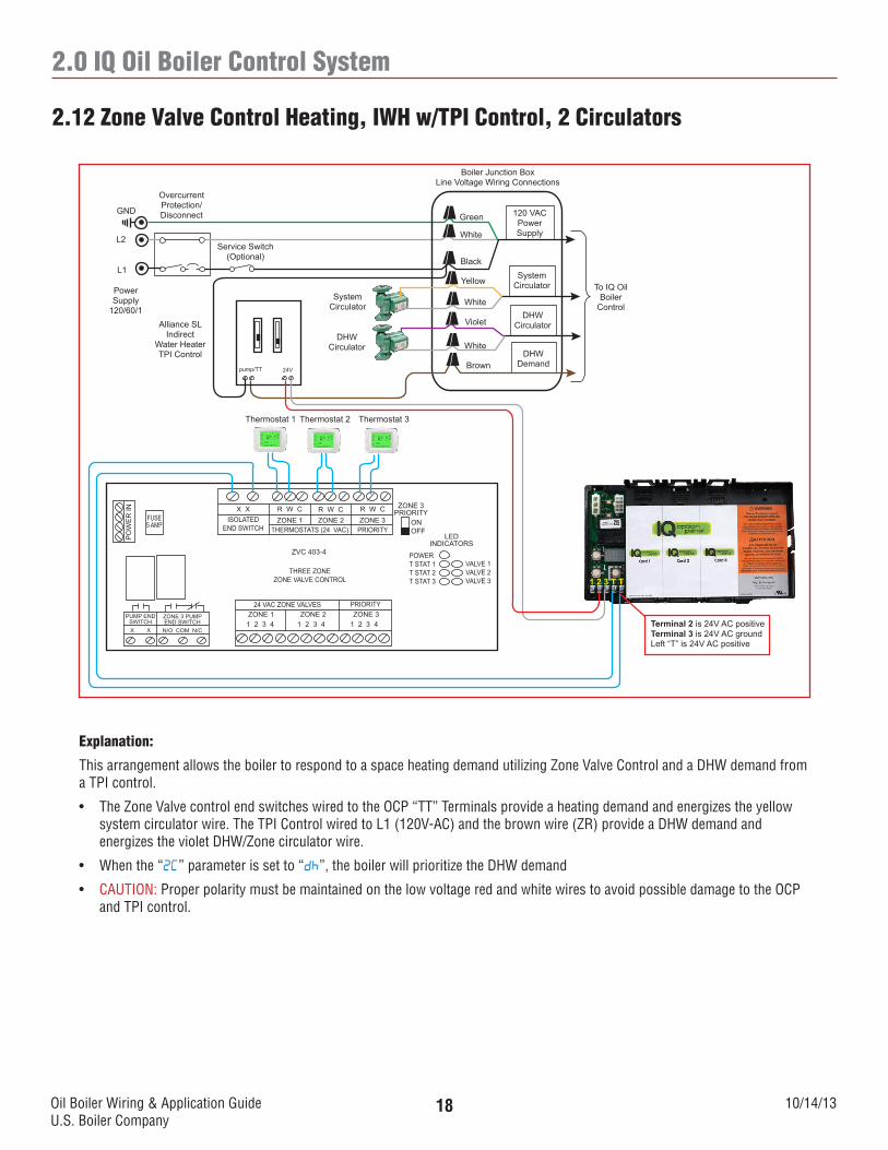
Explanation:
This arrangement allows the boiler to respond to a space heating demand utilizing Zone Valve Control and a DHW demand from a TPI control.
• TheZoneValvecontrolendswitcheswiredtotheOCP“TT”Terminalsprovideaheatingdemandandenergizestheyellowsystem circulator wire. The TPI Control wired to L1 (120V-AC) and the brown wire (ZR) provide a DHW demand and energizes the violet DHW/Zone circulator wire.
• Whenthe“2C” parameter is set to “dh”, the boiler will prioritize the DHW demand
• CAUTION: Proper polarity must be maintained on the low voltage red and white wires to avoid possible damage to the OCP and TPI control.
2.12 Zone Valve Control Heating, IWH w/TPI Control, 2 Circulators
120 VACPowerSupply
Boiler Junction BoxLine Voltage Wiring Connections
Green
White
Black
Service Switch(Optional)
OvercurrentProtection/DisconnectGND
L2
L1
PowerSupply
120/60/1
1 2 3 T T
Terminal 2 is 24V AC positiveTerminal 3 is 24V AC groundLeft “T” is 24V AC positive
SystemCirculator
SystemCirculatorYellow
DHWCirculator
White
DHWDemand
Violet
To IQ Oil Boiler
Control
Brown
Alliance SLIndirect
Water HeaterTPI Control
24Vpump/TT
WhiteDHW
Circulator
Thermostat 1 Thermostat 2
X X R W C R W C R W CZONE 1 ZONE 2 ZONE 3
THERMOSTATS (24 VAC) PRIORITYISOLATED
END SWITCH
ZVC 403-4
THREE ZONEZONE VALVE CONTROL
ZONE 1 ZONE 2 ZONE 3PRIORITY24 VAC ZONE VALVES
1 2 3 4 1 2 3 41 2 3 4
ZONE 3PRIORITY
ONOFF
LEDINDICATORS
POWERT STAT 1T STAT 2T STAT 3
VALVE 1VALVE 2VALVE 3
FUSE5 AMP
PO
WE
R IN
ZONE 3 PUMPEND SWITCH
PUMP END SWITCH
N/O COM N/CX X
Thermostat 3
Oil Boiler Wiring & Application GuideU.S. Boiler Company
10/14/1319
2.0 IQ Oil Boiler Control System
Explanation:
This arrangement allows the boiler to respond to a space heating demand utilizing Zone Valve Control and a DHW demand from an Aquastat control.
• ThezonevalvecontrolendswitcheswiredtotheOCP“TT”Terminals,provideaheatingdemand,andenergizestheyellowsystem circulator wire. The Aquastat control wired to L1 (120V-AC) and the brown wire (ZR) provide a DHW demand and energizes the violet DHW/Zone circulator wire.
• Whenthe“2C” parameter is set to “dh”, the boiler will prioritize the DHW demand.
• CAUTION: Proper polarity must be maintained on the red and white wires to avoid possible damage to the OCP.
2.13 Zone Valve Control Heating, IWH w/Aquastat Control, 2 Circulators
120 VACPowerSupply
Boiler Junction BoxLine Voltage Wiring Connections
Green
White
Black
Service Switch(Optional)
OvercurrentProtection/DisconnectGND
L2
L1
PowerSupply
120/60/1
1 2 3 T T
Terminal 2 is 24V AC positiveTerminal 3 is 24V AC groundLeft “T” is 24V AC positive
SystemCirculator
SystemCirculatorYellow
DHWCirculator
White
DHWDemand
Violet
To IQ Oil Boiler
Control
Brown
IWH Aquastat Control
WhiteDHW
Circulator
Thermostat 1 Thermostat 2
X X R W C R W C R W CZONE 1 ZONE 2 ZONE 3
THERMOSTATS (24 VAC) PRIORITYISOLATED
END SWITCH
ZVC 403-4
THREE ZONEZONE VALVE CONTROL
ZONE 1 ZONE 2 ZONE 3PRIORITY24 VAC ZONE VALVES
1 2 3 4 1 2 3 41 2 3 4
ZONE 3PRIORITY
ONOFF
LEDINDICATORS
POWERT STAT 1T STAT 2T STAT 3
VALVE 1VALVE 2VALVE 3
FUSE5 AMP
PO
WE
R IN
ZONE 3 PUMPEND SWITCH
PUMP END SWITCH
N/O COM N/CX X
Thermostat 3
Oil Boiler Wiring & Application GuideU.S. Boiler Company
10/14/1320
2.0 IQ Oil Boiler Control System
Explanation:
This arrangement allows the use of a zone valve control for heat and hot water, a TPI control and a single circulator with DHW priority.
• Aheatingorhotwaterdemandisprovidedtothe“T-T”terminalsontheIQBoilerControlbythezonevalveendswitchwhich energizes the yellow system circulator wire.
• CAUTION: Proper polarity must be maintained on the red and white wires to avoid possible damage to the TPI control.
2.14 Zone Valve Control Heating, IWH w/Aquastat Control, 1 Circulator
120 VACPowerSupply
Boiler Junction BoxLine Voltage Wiring Connections
Green
White
Black
Service Switch(Optional)
OvercurrentProtection/DisconnectGND
L2
L1
PowerSupply
120/60/1
1 2 3 T T
Terminal 2 is 24V AC positiveTerminal 3 is 24V AC groundLeft “T” is 24V AC positive
SystemCirculator
SystemCirculatorYellow
DHWCirculator
White
DHWDemand
Violet
To IQ Oil Boiler
Control
Brown
Thermostat 1 Thermostat 2
X X R W C R W C R W CZONE 1 ZONE 2 ZONE 3
THERMOSTATS (24 VAC) PRIORITYISOLATED
END SWITCH
ZVC 403-4
THREE ZONEZONE VALVE CONTROL
ZONE 1 ZONE 2 ZONE 3PRIORITY24 VAC ZONE VALVES
1 2 3 4 1 2 3 41 2 3 4
ZONE 3PRIORITY
ONOFF
LEDINDICATORS
POWERT STAT 1T STAT 2T STAT 3
VALVE 1VALVE 2VALVE 3
FUSE5 AMP
PO
WE
R IN
ZONE 3 PUMPEND SWITCH
PUMP END SWITCH
N/O COM N/CX X
Caution: When using a zone valve on an IWH, we strongly suggest the use of a mixing valve installed on the domestic water side of the indirect water heater
Alliance SLIndirect
Water HeaterTPI Control
24Vpump/TT
Oil Boiler Wiring & Application GuideU.S. Boiler Company
10/14/1321
2.0 IQ Oil Boiler Control System
Explanation:
This arrangement allows the boiler to respond to heating demands and control all the circulators from a zone switching relay.
2.15 Zone Valve Control Heating and IWH w/Aquastat Control, 1 Circulator
120 VACPowerSupply
Boiler Junction BoxLine Voltage Wiring Connections
Green
White
Black
Service Switch(Optional)
OvercurrentProtection/DisconnectGND
L2
L1
PowerSupply
120/60/1
1 2 3 T T
Terminal 2 is 24V AC positiveTerminal 3 is 24V AC groundLeft “T” is 24V AC positive
SystemCirculator
SystemCirculatorYellow
DHWCirculator
White
DHWDemand
Violet
To IQ Oil Boiler
Control
Brown
Thermostat 1 Thermostat 2
X X R W C R W C R W CZONE 1 ZONE 2 ZONE 3
THERMOSTATS (24 VAC) PRIORITYISOLATED
END SWITCH
ZVC 403-4
THREE ZONEZONE VALVE CONTROL
ZONE 1 ZONE 2 ZONE 3PRIORITY24 VAC ZONE VALVES
1 2 3 4 1 2 3 41 2 3 4
ZONE 3PRIORITY
ONOFF
LEDINDICATORS
POWERT STAT 1T STAT 2T STAT 3
VALVE 1VALVE 2VALVE 3
FUSE5 AMP
PO
WE
R IN
ZONE 3 PUMPEND SWITCH
PUMP END SWITCH
N/O COM N/CX X
Caution: When using a zone valve on an IWH, we strongly suggest the use of a mixing valve installed on the domestic water side of the indirect water heater
IWH Aquastat Control
Oil Boiler Wiring & Application GuideU.S. Boiler Company
10/14/1322
2.0 IQ Oil Boiler Control System
Explanation:
This arrangement allows the boiler to respond to multiple heating demands through a Zone Circulator Panel
Boiler Junction BoxLine Voltage Wiring Connections
Green
White
Black
Service Switch(Optional)
OvercurrentProtection/DisconnectGND
L2
L1
PowerSupply
120/60/1
1 2 3 T T
Terminal 2 is 24V AC positiveTerminal 3 is 24V AC groundLeft “T” is 24V AC positive
SystemCirculatorYellow
DHWCirculator
White
DHWDemand
Violet
To IQ Oil Boiler
Control
Brown
WhiteThermostat 1 Thermostat 2
ISOLATEDEND
SWITCH
SR 503-4
THREE ZONE SWITCHING RELAYLED
INDICATORS
POWER
ZONE 1
ZONE 2
ZONE 3
FUSE5
AMP
Thermostat 3
X X R W R W R W
ZONE 1 ZONE 2 ZONE 3PRIORITY
THERMOSTATS (24VAC)
FUSE5
AMP
FUSE5
AMP
FUSE5
AMP
ZONE 3PRIORITY
ONOFF
24 VAC
COM
INPUT120 VAC
120 VAC CIRCULATORS120 VAC
ZC ZR ZONE 1 ZONE 2ZONE 3
PRIORITYH H N H N H N H N H
Oil Boiler Wiring & Application GuideU.S. Boiler Company
10/14/1323
2.0 IQ Oil Boiler Control System
Explanation:
This arrangement allows the use of a zone switching relay for heat and hot water, a TPI control and a single circulator with DHW priority.
• CAUTION: Proper polarity must be maintained on the red and white wires to avoid possible damage to the OCP.
2.17 Zone Switching Relay Heating and IWH w/TPI Control
120 VACPowerSupply
Boiler Junction BoxLine Voltage Wiring Connections
Green
White
Black
Service Switch(Optional)
OvercurrentProtection/DisconnectGND
L2
L1
PowerSupply
120/60/1
1 2 3 T T
Terminal 2 is 24V AC positiveTerminal 3 is 24V AC groundLeft “T” is 24V AC positive
SystemCirculatorYellow
DHWCirculator
White
DHWDemand
Violet
To IQ Oil Boiler
Control
Brown
WhiteThermostat 1 Thermostat 2
ISOLATEDEND
SWITCH
SR 503-4
THREE ZONE SWITCHING RELAYLED
INDICATORS
POWER
ZONE 1
ZONE 2
ZONE 3
FUSE5
AMP
X X R W R W R W
ZONE 1 ZONE 2 ZONE 3PRIORITY
THERMOSTATS (24VAC)
FUSE5
AMP
FUSE5
AMP
FUSE5
AMP
ZONE 3PRIORITY
ONOFF
24 VAC
COM
INPUT120 VAC
120 VAC CIRCULATORS120 VAC
ZC ZR ZONE 1 ZONE 2ZONE 3
PRIORITYH H N H N H N H N H
Alliance SLIndirect
Water HeaterTPI Control
24Vpump/TT
Oil Boiler Wiring & Application GuideU.S. Boiler Company
10/14/1324
2.0 IQ Oil Boiler Control System
2.18 Zone Switching Relay Heating, IWH w/TPI Control
Explanation:
This arrangement allows the boiler to respond to heating demands and control all the circulators from a Zone Switching Relay. IHW takes priority through the IQ Boiler Control via the yellow system pump wire.
• ThezoneswitchingrelayendswitchwiredtotheOCP“TT”terminals,provideaheatingdemand,andenergizetheyellow system circulator wire. The TPI Control wired to L1 (120V-AC) and the brown wire (ZR) provide a DHW demand and energize the violet DHW/Zone circulator wire.
• Aheatdemandwillenergizetheyellowwirewhichwillsupplyvoltagetothezonepumpsviathe“ZC”terminalsonthezone relay. When the DHW demand activates, the IQ Boiler Control will de-energize the red wire and re-energize the yellow wire, providing there is still a call for heat.
• Whenthe“2C” parameter is set to “dh” the boiler will prioritize the DHW demand.
• CAUTION: Proper polarity must be maintained on the red and white wires to avoid possible damage to the OCP and TPI control.
120 VACPowerSupply
Boiler Junction BoxLine Voltage Wiring Connections
Green
White
Black
Service Switch(Optional)
OvercurrentProtection/DisconnectGND
L2
L1
PowerSupply
120/60/1
1 2 3 T T
Terminal 2 is 24V AC positiveTerminal 3 is 24V AC groundLeft “T” is 24V AC positive
SystemCirculatorYellow
DHWCirculator
White
DHWDemand
Violet
To IQ Oil Boiler
Control
Brown
WhiteThermostat 1 Thermostat 2
ISOLATEDEND
SWITCH
SR 503-4
THREE ZONE SWITCHING RELAYLED
INDICATORS
POWER
ZONE 1
ZONE 2
ZONE 3
FUSE5
AMP
X X R W R W R W
ZONE 1 ZONE 2 ZONE 3PRIORITY
THERMOSTATS (24VAC)
FUSE5
AMP
FUSE5
AMP
FUSE5
AMP
ZONE 3PRIORITY
ONOFF
24 VAC
COM
INPUT120 VAC
120 VAC CIRCULATORS120 VAC
ZC ZR ZONE 1 ZONE 2ZONE 3
PRIORITYH H N H N H N H N H
Alliance SLIndirectWater Heater
TPI Control
24Vpump/TT
Thermostat 3 DHWCirculator
Remove jumper
between ZC & ZR
Oil Boiler Wiring & Application GuideU.S. Boiler Company
10/14/1325
2.0 IQ Oil Boiler Control System
2.19 Zone Switching Relay Heating, IWH w/Aquastat Control
Explanation:
This arrangement allows the boiler to respond to heating demands and control all the circulators from a Zone Switching Relay. IHW takes priority through the IQ Boiler Control via the yellow system pump wire.
• ThezoneswitchingrelayendswitchwiredtotheOCP“TT”terminals,provideaheatingdemand,andenergizetheyellow system circulator wire. The Aquastat Control wired to L1 (120V-AC) and the brown wire (ZR) provide a DHW demand and energize the violet DHW/Zone circulator wire.
• Aheatdemandwillenergizetheyellowwirewhichwillsupplyvoltagetothezonepumpsviathe“ZC”terminalsonthezone relay. When the DHW demand activates, the IQ Boiler Control will de-energize the red wire and re-energize the yellow wire, providing there is still a call for heat.
• Whenthe“2C” parameter is set to “dh” the boiler will prioritize the DHW demand.
120 VACPowerSupply
Boiler Junction BoxLine Voltage Wiring Connections
Green
White
Black
Service Switch(Optional)
OvercurrentProtection/DisconnectGND
L2
L1
PowerSupply
120/60/1
1 2 3 T T
Terminal 2 is 24V AC positiveTerminal 3 is 24V AC groundLeft “T” is 24V AC positive
SystemCirculatorYellow
DHWCirculator
White
DHWDemand
Violet
To IQ Oil Boiler
Control
Brown
WhiteThermostat 1 Thermostat 2
ISOLATEDEND
SWITCH
SR 503-4
THREE ZONE SWITCHING RELAYLED
INDICATORS
POWER
ZONE 1
ZONE 2
ZONE 3
FUSE5
AMP
X X R W R W R W
ZONE 1 ZONE 2 ZONE 3PRIORITY
THERMOSTATS (24VAC)
FUSE5
AMP
FUSE5
AMP
FUSE5
AMP
ZONE 3PRIORITY
ONOFF
24 VAC
COM
INPUT120 VAC
120 VAC CIRCULATORS120 VAC
ZC ZR ZONE 1 ZONE 2ZONE 3
PRIORITYH H N H N H N H N H
Thermostat 3 DHWCirculator
IWH Aquastat Control
Remove jumper
between ZC & ZR
Oil Boiler Wiring & Application GuideU.S. Boiler Company
10/14/1326
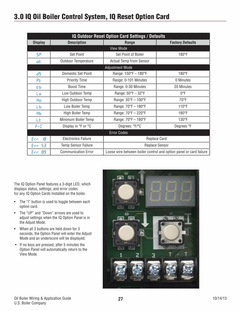
3.0 IQ Oil Boiler Control System, IQ Reset Option Card
The IQ Outdoor Reset Option Card is an auxiliary control designed specifically for all Burnham products that feature the IQ Control System.
The device than plugs into the IQ Option Panel making it the quickest, simplest way to install the energy savings and improved comfort of a full-featured outdoor reset system in any nearly heating system.
The included weatherproof outdoor temperature sensor is mounted outside the building, and a 2-wire connection is all that’s required to connect the Option Card. An additional 2-wire connection to the DHW Aquastat provides a DHW demand.
The IQ Outdoor Reset Option Card contains an impressive list of features normally found only on expensive, stand-alone control systems. A simple click is all it takes to add the these great features:
• Whenthe“2C” parameter is set to “dh”, the boiler will prioritize the DHW demand.
• TheIQOutdoorResetOptionCardwillraiseorlowertheheatingsystemwatertemperaturesetpointbasedonmeasuredoutside air temperature and will be overridden on a DHW demand.
• CAUTION: Proper polarity must be maintained on the low voltage red and white wires to avoid possible damage to the OCP and TPI Control.
3.3 Single Zone Heating, Indirect Water Heater w/TPI Control
120 VACPowerSupply
SystemCirculator
Boiler Junction BoxLine Voltage Wiring Connections
Green
White
Black
Yellow
SystemCirculator
Service Switch(Optional)
OvercurrentProtection/DisconnectGND
L2
L1
PowerSupply
120/60/1
Brown
To IQ Oil Boiler
Control
DHWCirculator
White
DHWDemand
Violet
Thermostat 1
1 2 3 T T 1 2 3 4
Terminal 2 is 24V-AC PositiveTerminal 3 is 24V-Gnd
Left “T” is 24V-AC Positive
Alliance SLIndirect
Water HeaterTPI Control
24Vpump/TT
DHWCirculator White
Oil Boiler Wiring & Application GuideU.S. Boiler Company
10/14/1331
3.0 IQ Oil Boiler Control System, IQ Reset Option Card
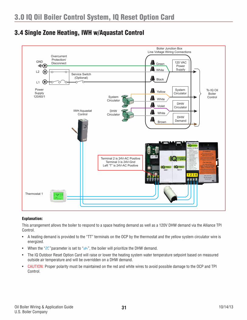
Explanation:
This arrangement allows the boiler to respond to a space heating demand as well as a 120V DHW demand via the Alliance TPI Control.
• Whenthe“2C”parameter is set to “dh”, the boiler will prioritize the DHW demand.
• TheIQOutdoorResetOptionCardwillraiseorlowertheheatingsystemwatertemperaturesetpointbasedonmeasuredoutside air temperature and will be overridden on a DHW demand.
• CAUTION: Proper polarity must be maintained on the red and white wires to avoid possible damage to the OCP and TPI Control.
3.4 Single Zone Heating, IWH w/Aquastat Control
120 VACPowerSupply
SystemCirculator
Boiler Junction BoxLine Voltage Wiring Connections
Green
White
Black
Yellow
SystemCirculator
Service Switch(Optional)
OvercurrentProtection/DisconnectGND
L2
L1
PowerSupply
120/60/1
Brown
To IQ Oil Boiler
Control
DHWCirculator
White
DHWDemand
Violet
Thermostat 1
1 2 3 T T 1 2 3 4
Terminal 2 is 24V-AC PositiveTerminal 3 is 24V-Gnd
Left “T” is 24V-AC Positive
DHWCirculator White
IWH Aquastat Control
Oil Boiler Wiring & Application GuideU.S. Boiler Company
10/14/1332
3.0 IQ Oil Boiler Control System, IQ Reset Option Card
Explanation:
This arrangement allows the boiler to respond to a space heating demand utilizing Taco 3-wire zone valves and a DHW demand from a TPI control.
• ThezonevalveendswitcheswiredtotheOCP“TT”terminalsprovideaheatingdemandandenergizestheyellowsystemcirculator wire. The TPI Control wired to the IQ Outdoor Reset Option Card “3” & “4” terminals provides a DHW demand and energizes the red DHW/Zone circulator wire.
• TheIQBoilerControlparameter“dh” must be set to “dh”. Priority time and DHW Setpoint can be set on the IQ Outdoor Reset Option Card.
• TheIQOutdoorResetOptionCardwillraiseorlowertheheatingsystemwatertemperaturesetpointbasedonmeasuredoutside air temperature and will be overridden on a DHW demand.
• CAUTION: Proper polarity must be maintained on the red and white wires to avoid possible damage to the OCP and TPI control.
3.5 Zone Valves Heating, IWH w/TPI Control, 2 Circulators
120 VACPowerSupply
SystemCirculator
Boiler Junction BoxLine Voltage Wiring Connections
Green
White
Black
Yellow
SystemCirculator
Service Switch(Optional)
OvercurrentProtection/DisconnectGND
L2
L1
PowerSupply
120/60/1
Brown
To IQ Oil Boiler
Control
DHWCirculator
White
DHWDemand
VioletDHW
Circulator White
1 2 3 T T 1 2 3 4
Terminal 2 is 24V-AC PositiveTerminal 3 is 24V-GndLeft “T” is 24V-AC Positive
Alliance SLIndirect
Water HeaterTPI Control
Thermostat 3Thermostat 2Thermostat 1
24V ac Positive
40VA Transformer
Field Installed
Power Supply
120/60/1
L1L2
NOTEZone Valve Terminal 2 must be
connected to 24 V ACCommon failure to do so will result in
damaged equipment
24Vpump/TT
Oil Boiler Wiring & Application GuideU.S. Boiler Company
10/14/1333
3.0 IQ Gas Boiler Control System, IQ Reset Option Card
3.6 Zone Valves Heating, IWH w/TPI Control, 1 Circulator, No Priority
120 VACPowerSupply
SystemCirculator
Boiler Junction BoxLine Voltage Wiring Connections
Green
White
Black
Yellow
SystemCirculator
Service Switch(Optional)
OvercurrentProtection/DisconnectGND
L2
L1
PowerSupply
120/60/1
Brown
To IQ Oil Boiler
Control
DHWCirculator
White
DHWDemand
VioletDHW
Circulator White
1 2 3 T T 1 2 3 4
Terminal 2 is 24V-AC PositiveTerminal 3 is 24V-GndLeft “T” is 24V-AC Positive
Thermostat 3Thermostat 2Thermostat 1
24V ac Positive
40VA Transformer
Field Installed
Power Supply
120/60/1
L1L2
NOTEZone Valve Terminal 2 must be
connected to 24 V ACCommon failure to do so will result in
damaged equipment
IWH Aquastat Control
Explanation:
This arrangement allows the boiler to respond to a space heating demand utilizing Taco 3-wire zone valves and a DHW demand from an Aquastat control.
• ThezonevalveendswitcheswiredtotheOCP“TT”terminalsprovideaheatingdemandandenergizestheyellowsystemcirculator wire. The Aquastat control connected wired to the IQ Outdoor Reset Option Card “3” & “4” terminals provides a DHW demand and energizes the red DHW/Zone circulator wire.
• TheIQBoilerControlparameter“dh” must be set to “dh”. Priority time and DHW Setpoint can be set on the IQ Outdoor Reset Option Card
• TheIQOutdoorResetOptionCardwillraiseorlowertheheatingsystemwatertemperaturesetpointbasedonmeasuredoutside air temperature and will be overridden on a DHW demand.
• CAUTION: Proper polarity must be maintained on the red and white wires to avoid possible damage to the OCP.
Oil Boiler Wiring & Application GuideU.S. Boiler Company
10/14/1334
3.0 IQ Oil Boiler Control System, IQ Reset Option Card
3.7 Zone Valve Heating, IWH w/TPI Control, 1 Circulator, No Priority
1 2 3 T T 1 2 3 4
120 VACPowerSupply
Boiler Junction BoxLine Voltage Wiring Connections
Green
White
Black
Service Switch(Optional)
OvercurrentProtection/DisconnectGND
L2
L1
PowerSupply
120/60/1
Thermostat 2Thermostat 1
24V ac Positive
40VA Transformer
Field Installed
Power Supply
120/60/1
L1L2
NOTEZone Valve Terminal 2 must be
connected to 24 V ACCommon failure to do so will result in
damaged equipment
SystemCirculator
SystemCirculatorYellow
DHWCirculator
White
DHWDemand
Violet
To IQ Oil Boiler
Control
Brown
Alliance SLIndirect
Water HeaterTPI Control
24Vpump/TT
This application offers no DHW priority
Caution: When using a zone valve on an IWH, we strongly suggest the use of a mixing valve installed on the domestic water side of the indirect water heater
Terminal 2 is 24V-AC PositiveTerminal 3 is 24V-GndLeft “T” is 24V-AC Positive
Terminal 3 is Grounded 24V-AC ComTerminal 4 is 24V-AC Positive
Explanation:
This arrangement allows the boiler to respond to a space heating demand utilizing Taco 3-wire zone valves and a DHW demand from a TPI control.
• ThezonevalveendswitcheswiredtotheOCP“TT”terminalsprovideaheatingdemandandenergizestheyellowsystemcirculator wire. The DHW zone valve end switch switch wired to the IQ Outdoor Reset Option Card “3” & “4” terminals provides a DHW demand and energizes the violet DHW/Zone circulator wire.
• TheIQBoilerControlparameter“2C” must be set to “dh”. Priority time and DHW setpoint can be set on the IQ Outdoor Reset Option Card
• TheIQOutdoorResetOptionCardwillraiseorlowertheheatingsystemwatertemperaturesetpointbasedonmeasuredoutside air temperature and will be overridden on a DHW demand.
• CAUTION: Proper polarity must be maintained on the red and white wires to avoid possible damage to the OCP and TPI control.
Oil Boiler Wiring & Application GuideU.S. Boiler Company
10/14/1335
3.0 IQ Oil Boiler Control System, IQ Reset Option Card
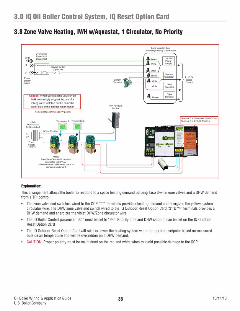
3.8 Zone Valve Heating, IWH w/Aquastat, 1 Circulator, No Priority
1 2 3 T T 1 2 3 4
120 VACPowerSupply
Boiler Junction BoxLine Voltage Wiring Connections
Green
White
Black
Service Switch(Optional)
OvercurrentProtection/DisconnectGND
L2
L1
PowerSupply
120/60/1
Thermostat 2Thermostat 1
24V ac Positive
40VA Transformer
Field Installed
Power Supply
120/60/1
L1L2
NOTEZone Valve Terminal 2 must be
connected to 24 V ACCommon failure to do so will result in
damaged equipment
SystemCirculator
SystemCirculatorYellow
DHWCirculator
White
DHWDemand
Violet
To IQ Oil Boiler
Control
Brown
This application offers no DHW priority
Caution: When using a zone valve on an IWH, we strongly suggest the use of a mixing valve installed on the domestic water side of the indirect water heater
Terminal 3 is Grounded 24V-AC ComTerminal 4 is 24V-AC Positive
IWH Aquastat Control
Explanation:
This arrangement allows the boiler to respond to a space heating demand utilizing Taco 3-wire zone valves and a DHW demand from a TPI control.
• ThezonevalveendswitcheswiredtotheOCP“TT”terminalsprovideaheatingdemandandenergizestheyellowsystemcirculator wire. The DHW zone valve end switch wired to the IQ Outdoor Reset Option Card “3” & “4” terminals provides a DHW demand and energizes the violet DHW/Zone circulator wire.
• TheIQBoilerControlparameter“2C” must be set to “dh”. Priority time and DHW setpoint can be set on the IQ Outdoor Reset Option Card
• TheIQOutdoorResetOptionCardwillraiseorlowertheheatingsystemwatertemperaturesetpointbasedonmeasuredoutside air temperature and will be overridden on a DHW demand.
• CAUTION: Proper polarity must be maintained on the red and white wires to avoid possible damage to the OCP.
Oil Boiler Wiring & Application GuideU.S. Boiler Company
10/14/1336
3.0 IQ Oil Boiler Control System, IQ Reset Option Card
3.9 Zone Valve Control Heating, IWH w/TPI Control, 2 Circulators
120 VACPowerSupply
Boiler Junction BoxLine Voltage Wiring Connections
Green
White
Black
Service Switch(Optional)
OvercurrentProtection/DisconnectGND
L2
L1
PowerSupply
120/60/1System
Circulator
SystemCirculatorYellow
DHWCirculator
White
DHWDemand
To IQ Oil Boiler
Control
Brown
1 2 3 T T 1 2 3 4
Thermostat 1 Thermostat 2
X X R W C R W C R W CZONE 1 ZONE 2 ZONE 3
THERMOSTATS (24 VAC) PRIORITYISOLATED
END SWITCH
ZVC 403-4
THREE ZONEZONE VALVE CONTROL
ZONE 1 ZONE 2 ZONE 3PRIORITY24 VAC ZONE VALVES
1 2 3 4 1 2 3 41 2 3 4
ZONE 3PRIORITY
ONOFF
LEDINDICATORS
POWERT STAT 1T STAT 2T STAT 3
VALVE 1VALVE 2VALVE 3
FUSE5 AMP
PO
WE
R IN
ZONE 3 PUMPEND SWITCH
PUMP END SWITCH
N/O COM N/CX X
Alliance SLIndirect
Water HeaterTPI Control
Thermostat 3
Terminal 2 is 24V-ac PositiveTerminal 3 is 24V-Gnd
Left “T” is 24V-ac Positive
24Vpump/TT
DHWCirculator
Violet
White
Explanation:
This arrangement allows the boiler to respond to a space heating demand utilizing a zone valve control and a DHW demand from a TPI control.
• TheheatingzonevalvecontrolendswitchwiredtotheOCP“TT”terminalsprovideaheatingdemandandenergizestheyellow system circulator wire. The TPI Control wired to the IQ Outdoor Reset Option Card “3” & “4” terminals provides a DHW demand and energizes the red DHW/Zone circulator wire.
• TheIQBoilerControlparameter“2C” must be set to “dh”. Priority time and DHW setpoint can be set on the IQ Outdoor Reset Option Card.
• TheIQOutdoorResetOptionCardwillraiseorlowertheheatingsystemwatertemperaturesetpointbasedonmeasuredoutside air temperature and will be overridden on a DHW demand.
• CAUTION: Proper polarity must be maintained on the red and white wires to avoid possible damage to the OCP and the TPI control.
Oil Boiler Wiring & Application GuideU.S. Boiler Company
10/14/1337
3.0 IQ Oil Boiler Control System, IQ Reset Option Card
3.10 Zone Valve Control Heating, IWH w/Aquastat, 2 Circulators
120 VACPowerSupply
Boiler Junction BoxLine Voltage Wiring Connections
Green
White
Black
Service Switch(Optional)
OvercurrentProtection/DisconnectGND
L2
L1
PowerSupply
120/60/1System
Circulator
SystemCirculatorYellow
DHWCirculator
White
DHWDemand
To IQ Oil Boiler
Control
Brown
1 2 3 T T 1 2 3 4
Thermostat 1 Thermostat 2
X X R W C R W C R W CZONE 1 ZONE 2 ZONE 3
THERMOSTATS (24 VAC) PRIORITYISOLATED
END SWITCH
ZVC 403-4
THREE ZONEZONE VALVE CONTROL
ZONE 1 ZONE 2 ZONE 3PRIORITY24 VAC ZONE VALVES
1 2 3 4 1 2 3 41 2 3 4
ZONE 3PRIORITY
ONOFF
LEDINDICATORS
POWERT STAT 1T STAT 2T STAT 3
VALVE 1VALVE 2VALVE 3
FUSE5 AMP
PO
WE
R IN
ZONE 3 PUMPEND SWITCH
PUMP END SWITCH
N/O COM N/CX X
Thermostat 3
Terminal 2 is 24V-AC PositiveTerminal 3 is 24V-Gnd
Left “T” is 24V-AC PositiveRight “T” is 24V-AC Gnd
DHWCirculator
Violet
White
IWH Aquastat Control
Explanation:
This arrangement allows the boiler to respond to a space heating demand utilizing a zone valve control and a DHW demand from an Aquastat control.
• TheheatingzonevalvecontrolendswitchwiredtotheOCP“TT”terminalsprovideaheatingdemandandenergizestheyellow system circulator wire. The Aquastat control wired to the IQ Outdoor Reset Option Card “3” & “4” terminals provides a DHW demand and energizes the red DHW/Zone circulator wire.
• TheIQBoilerControlparameter“2C” must be set to “dh”. Priority time and DHW setpoint can be set on the IQ Outdoor Reset Option Card.
• TheIQOutdoorResetOptionCardwillraiseorlowertheheatingsystemwatertemperaturesetpointbasedonmeasuredoutside air temperature and will be overridden on a DHW demand.
• CAUTION: Proper polarity must be maintained on the red and white wires to avoid possible damage to the OCP.
Oil Boiler Wiring & Application GuideU.S. Boiler Company
10/14/1338
3.0 IQ Oil Boiler Control System, IQ Reset Option Card
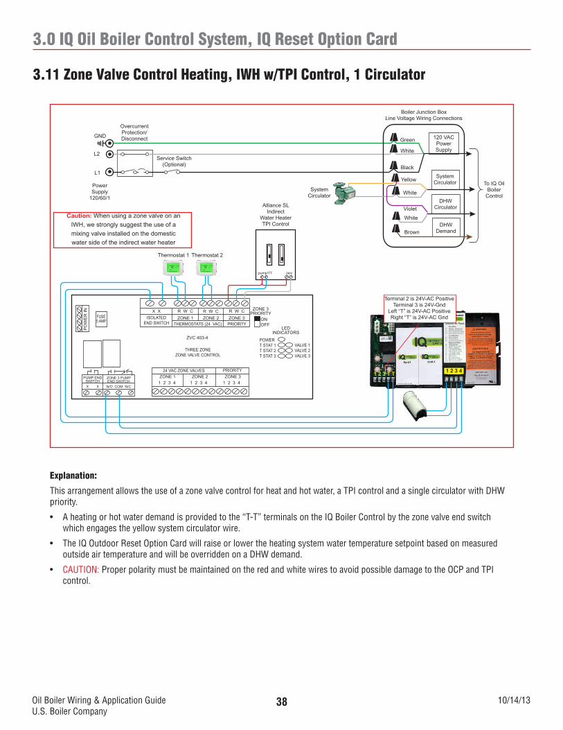
3.11 Zone Valve Control Heating, IWH w/TPI Control, 1 Circulator
120 VACPowerSupply
Boiler Junction BoxLine Voltage Wiring Connections
Green
White
Black
Service Switch(Optional)
OvercurrentProtection/DisconnectGND
L2
L1
PowerSupply
120/60/1System
Circulator
SystemCirculatorYellow
DHWCirculator
White
DHWDemand
To IQ Oil Boiler
Control
Brown
1 2 3 T T 1 2 3 4
Thermostat 1 Thermostat 2
X X R W C R W C R W CZONE 1 ZONE 2 ZONE 3
THERMOSTATS (24 VAC) PRIORITYISOLATED
END SWITCH
ZVC 403-4
THREE ZONEZONE VALVE CONTROL
ZONE 1 ZONE 2 ZONE 3PRIORITY24 VAC ZONE VALVES
1 2 3 4 1 2 3 41 2 3 4
ZONE 3PRIORITY
ONOFF
LEDINDICATORS
POWERT STAT 1T STAT 2T STAT 3
VALVE 1VALVE 2VALVE 3
FUSE5 AMP
PO
WE
R IN
ZONE 3 PUMPEND SWITCH
PUMP END SWITCH
N/O COM N/CX X
Terminal 2 is 24V-AC PositiveTerminal 3 is 24V-Gnd
Left “T” is 24V-AC PositiveRight “T” is 24V-AC Gnd
Violet
White
Alliance SLIndirect
Water HeaterTPI Control
24Vpump/TT
Caution: When using a zone valve on an IWH, we strongly suggest the use of a mixing valve installed on the domestic water side of the indirect water heater
Explanation:
This arrangement allows the use of a zone valve control for heat and hot water, a TPI control and a single circulator with DHW priority.
• Aheatingorhotwaterdemandisprovidedtothe“T-T”terminalsontheIQBoilerControlbythezonevalveendswitchwhich engages the yellow system circulator wire.
• TheIQOutdoorResetOptionCardwillraiseorlowertheheatingsystemwatertemperaturesetpointbasedonmeasuredoutside air temperature and will be overridden on a DHW demand.
• CAUTION: Proper polarity must be maintained on the red and white wires to avoid possible damage to the OCP and TPI control.
Oil Boiler Wiring & Application GuideU.S. Boiler Company
10/14/1339
3.0 IQ Oil Boiler Control System, IQ Reset Option Card
3.12 Zone Valve Control Heating and IWH w/Aquastat Control, 1 Circulator
120 VACPowerSupply
Boiler Junction BoxLine Voltage Wiring Connections
Green
White
Black
Service Switch(Optional)
OvercurrentProtection/DisconnectGND
L2
L1
PowerSupply
120/60/1System
Circulator
SystemCirculatorYellow
DHWCirculator
White
DHWDemand
To IQ Oil Boiler
Control
Brown
1 2 3 T T 1 2 3 4
Thermostat 1 Thermostat 2
X X R W C R W C R W CZONE 1 ZONE 2 ZONE 3
THERMOSTATS (24 VAC) PRIORITYISOLATED
END SWITCH
ZVC 403-4
THREE ZONEZONE VALVE CONTROL
ZONE 1 ZONE 2 ZONE 3PRIORITY24 VAC ZONE VALVES
1 2 3 4 1 2 3 41 2 3 4
ZONE 3PRIORITY
ONOFF
LEDINDICATORS
POWERT STAT 1T STAT 2T STAT 3
VALVE 1VALVE 2VALVE 3
FUSE5 AMP
PO
WE
R IN
ZONE 3 PUMPEND SWITCH
PUMP END SWITCH
N/O COM N/CX X
Terminal 2 is 24V-AC PositiveTerminal 3 is 24V-Gnd
Left “T” is 24V-AC PositiveRight “T” is 24V-AC Gnd
Violet
WhiteCaution: When using a zone valve on an IWH, we strongly suggest the use of a mixing valve installed on the domestic water side of the indirect water heater IWH Aquastat
Control
Explanation:
This arrangement allows the use of a zone valve control for heat and hot water, an Aquastat control and a single circulator with DHW priority.
• Aheatingorhotwaterdemandisprovidedtothe“T-T”terminalsontheIQboilerbythezonevalveendswitchwhichenergizes the yellow system circulator wire.
• TheIQOutdoorResetOptionCardwillraiseorlowertheheatingsystemwatertemperaturesetpointbasedonmeasuredoutside air temperature and will be overridden on a DHW demand.
Oil Boiler Wiring & Application GuideU.S. Boiler Company
10/14/1340
3.0 IQ Oil Boiler Control System, IQ Reset Option Card
3.13 Zone Switching Relay, IWH w/TPI Control
1 2 3 T T 1 2 3 4
Terminal 2 is 24V-AC PositiveTerminal 3 is 24V-Gnd
Left “T” is 24V-AC PositiveRight “T” is 24V-AC Gnd
120 VACPowerSupply
Boiler Junction BoxLine Voltage Wiring Connections
Green
White
Black
Service Switch(Optional)
OvercurrentProtection/DisconnectGND
L2
L1
PowerSupply
120/60/1
SystemCirculatorYellow
DHWCirculator
DHWDemand
Violet
To IQ Oil Boiler
Control
Brown
WhiteThermostat 1 Thermostat 2
ISOLATEDEND
SWITCH
SR 503-4
THREE ZONE SWITCHING RELAYLED
INDICATORS
POWER
ZONE 1
ZONE 2
ZONE 3
FUSE5
AMP
X X R W R W R W
ZONE 1 ZONE 2 ZONE 3PRIORITY
THERMOSTATS (24VAC)
FUSE5
AMP
FUSE5
AMP
FUSE5
AMP
ZONE 3PRIORITY
ONOFF
24 VAC
COM
INPUT120 VAC
120 VAC CIRCULATORS120 VAC
ZC ZR ZONE 1 ZONE 2ZONE 3
PRIORITYH H N H N H N H N H
Alliance SLIndirectWater Heater
TPI Control
24Vpump/TT
Thermostat 3 DHWCirculator
Remove jumper
between ZC & ZR
NOTESupply power to Zone Switching Relay
from same discount as boiler
Explanation:
This arrangement allows the boiler to respond to a space heating demand utilizing a zone switching relay and a DHW demand from a TPI control.
• TheheatingzonevalveendswitcheswiredtotheOCP“TT”terminalsprovideaheatingdemandandenergizestheyellow system circulator wire. The TPI Control wired to the IQ Outdoor Reset Option Card “3” & “4” terminals provides a DHW demand and energizes the red DHW/Zone circulator wire.
• TheIQBoilerControlparameter“2C” must be set to “dh”. Priority time and DHW setpoint can be set on the IQ Outdoor reset option card.
• TheIQOutdoorResetOptionCardwillraiseorlowertheheatingsystemwatertemperaturesetpointbasedonmeasuredoutside air temperature and will be overridden on a DHW demand.
• CAUTION: Proper polarity must be maintained on the red and white wires to avoid possible damage to the OCP and the TPI Control.
Oil Boiler Wiring & Application GuideU.S. Boiler Company
10/14/1341
3.0 IQ Oil Boiler Control System, IQ Reset Option Card
3.14 Zone Switching Relay, IWH w/Aquastat Control
1 2 3 T T 1 2 3 4
Terminal 2 is 24V-AC PositiveTerminal 3 is 24V-Gnd
Left “T” is 24V-AC PositiveRight “T” is 24V-AC Gnd
120 VACPowerSupply
Boiler Junction BoxLine Voltage Wiring Connections
Green
White
Black
Service Switch(Optional)
OvercurrentProtection/DisconnectGND
L2
L1
PowerSupply
120/60/1
SystemCirculatorYellow
DHWCirculator
DHWDemand
Violet
To IQ Oil Boiler
Control
Brown
WhiteThermostat 1 Thermostat 2
ISOLATEDEND
SWITCH
SR 503-4
THREE ZONE SWITCHING RELAYLED
INDICATORS
POWER
ZONE 1
ZONE 2
ZONE 3
FUSE5
AMP
X X R W R W R W
ZONE 1 ZONE 2 ZONE 3PRIORITY
THERMOSTATS (24VAC)
FUSE5
AMP
FUSE5
AMP
FUSE5
AMP
ZONE 3PRIORITY
ONOFF
24 VAC
COM
INPUT120 VAC
120 VAC CIRCULATORS120 VAC
ZC ZR ZONE 1 ZONE 2ZONE 3
PRIORITYH H N H N H N H N H
Thermostat 3 DHWCirculator
Remove jumper
between ZC & ZR
IWH Aquastat Control
NOTESupply power to Zone Switching Relay
from same discount as boiler
Explanation:
This arrangement allows the boiler to respond to a space heating demand utilizing a zone switching relay and a DHW demand from an Aquastat control.
• TheheatingzonevalveendswitcheswiredtotheOCP“TT”terminalsprovideaheatingdemandandenergizestheyellow system circulator wire. The TPI Control wired to the IQ Outdoor Reset Option Card “3” & “4” terminals provides a DHW demand and energizes the red DHW/Zone circulator wire.
• TheIQBoilerControlparameter“2C” must be set to “dh”. Priority time and DHW setpoint can be set on the IQ Outdoor reset option card.
• TheIQOutdoorResetOptionCardwillraiseorlowertheheatingsystemwatertemperaturesetpointbasedonmeasuredoutside air temperature and will be overridden on a DHW demand.
• CAUTION: Proper polarity must be maintained on the red and white wires to avoid possible damage to the OCP.
Oil Boiler Wiring & Application GuideU.S. Boiler Company
10/14/1342
Notes
Oil Boiler Wiring & Application GuideU.S. Boiler Company
10/14/1343
Notes
Oil Boiler Wiring & Application GuideU.S. Boiler Company


![MELSEC iQ-F FX5 User's Manual (ASLINK)³_logikai... · 2017-06-20 · 4 [WIRING PRECAUTIONS] [WIRING PRECAUTIONS] WARNING Make sure to cut off all phases of the power supply externally](https://static.documents.pub/doc/80x56/5e29a80bd29d0733be4c6535/melsec-iq-f-fx5-users-manual-aslink-logikai-2017-06-20-4-wiring-precautions.jpg)


