35
MQXF shell fracture modeling P. Ferracin, E. Takala 22. February 2019 CERN E. Anderssen, H. Pan, G. Vallone

logo
area
MQXF shell fracture modeling
P. Ferracin, E. Takala
22. February 2019
CERN
E. Anderssen, H. Pan, G. Vallone
Outline
• Overview of 3D models
• Shell length comparison (MQXFS/A/B)
• Why sub-modeling is needed?
• Submodel
• Mesh size
• Plastic deformation
• Linear elastic fracture mechanics (LEFM)
• 2D Fracture propagation modeling
• Study case: MQXFBP1 hole in the corner axis
• Conclusion
Eelis Takala 2

Eelis Takala 3
Introduction (1)
3
Different shell sizes:
Short Long
S 387 774
AP1 325.6 651.3
BP1 341.5 683
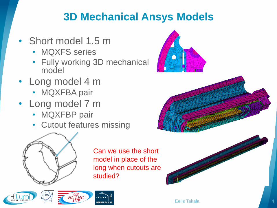
3D Mechanical Ansys Models
• Short model 1.5 m• MQXFS series
• Fully working 3D mechanical model
• Long model 4 m• MQXFBA pair
• Long model 7 m• MQXFBP pair
• Cutout features missing
Eelis Takala 4
Can we use the short
model in place of the
long when cutouts are
studied?
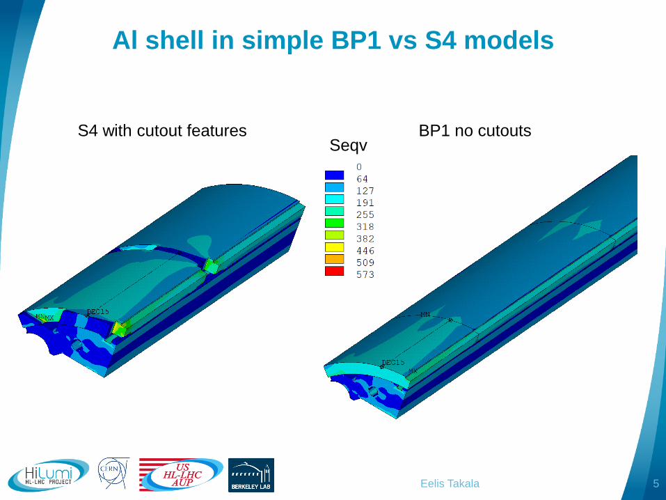
Al shell in simple BP1 vs S4 models
Eelis Takala 5
BP1 no cutoutsS4 with cutout featuresSeqv

Stress components simple BP1 vs S4
Stress is at similar level
in the middle of the shell
=> short model is a
common representative
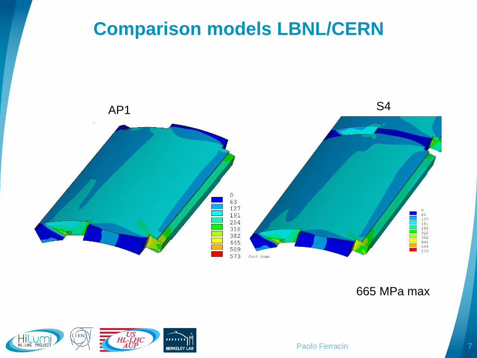
Comparison models LBNL/CERN
Paolo Ferracin 7
665 MPa max
AP1 S4
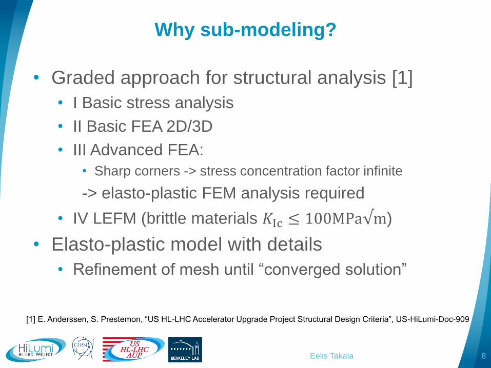
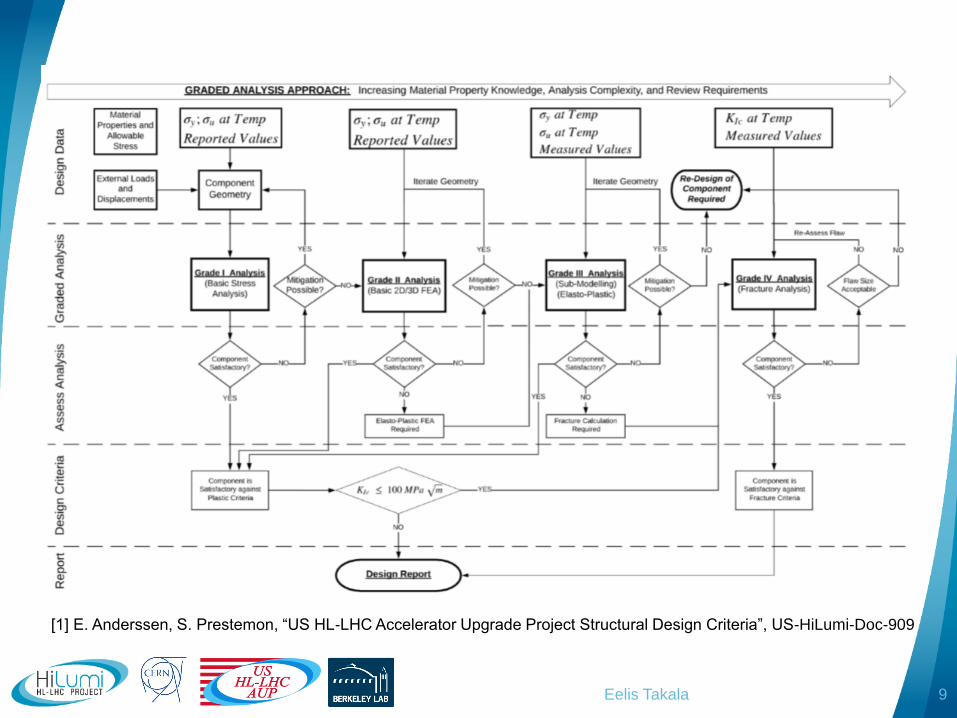
Why sub-modeling?
• Graded approach for structural analysis [1]
• I Basic stress analysis
• II Basic FEA 2D/3D
• III Advanced FEA:
• Sharp corners -> stress concentration factor infinite
-> elasto-plastic FEM analysis required
• IV LEFM (brittle materials 𝐾Ic ≤ 100MPa√m)
• Elasto-plastic model with details
• Refinement of mesh until “converged solution”
Eelis Takala 8
[1] E. Anderssen, S. Prestemon, “US HL-LHC Accelerator Upgrade Project Structural Design Criteria”, US-HiLumi-Doc-909
Eelis Takala 9
[1] E. Anderssen, S. Prestemon, “US HL-LHC Accelerator Upgrade Project Structural Design Criteria”, US-HiLumi-Doc-909
Eelis Takala
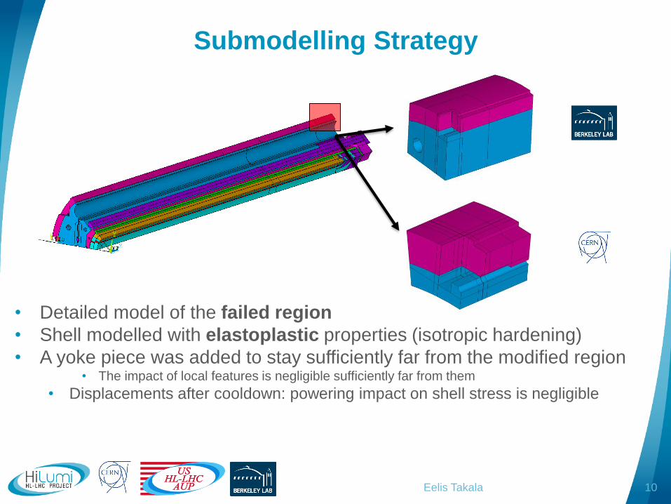
Submodelling Strategy
• Detailed model of the failed region
• Shell modelled with elastoplastic properties (isotropic hardening)
• A yoke piece was added to stay sufficiently far from the modified region• The impact of local features is negligible sufficiently far from them
• Displacements after cooldown: powering impact on shell stress is negligible
10
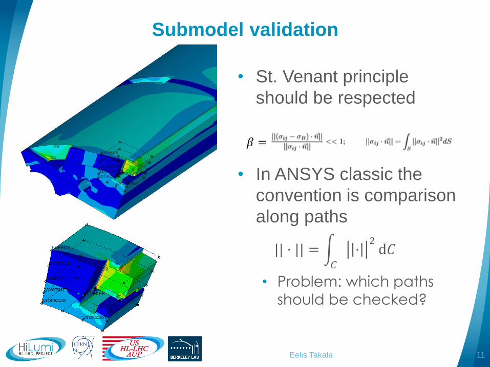
Submodel validation
11Eelis Takala
• St. Venant principle
should be respected
• In ANSYS classic the
convention is comparison
along paths
|| ⋅ || = න𝐶
⋅2d𝐶
• Problem: which paths
should be checked?
𝛽 =
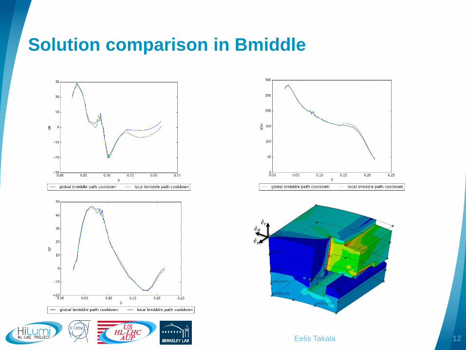
Solution comparison in Bmiddle
Eelis Takala 12
Ƹ𝑒𝜃Ƹ𝑒𝑟
Ƹ𝑒𝑧
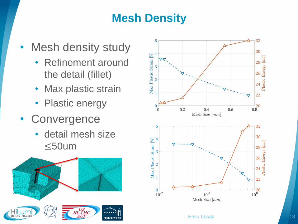
Mesh Density
• Mesh density study
• Refinement around
the detail (fillet)
• Max plastic strain
• Plastic energy
• Convergence
• detail mesh size
≤50um
Eelis Takala 13
Sub-modeling
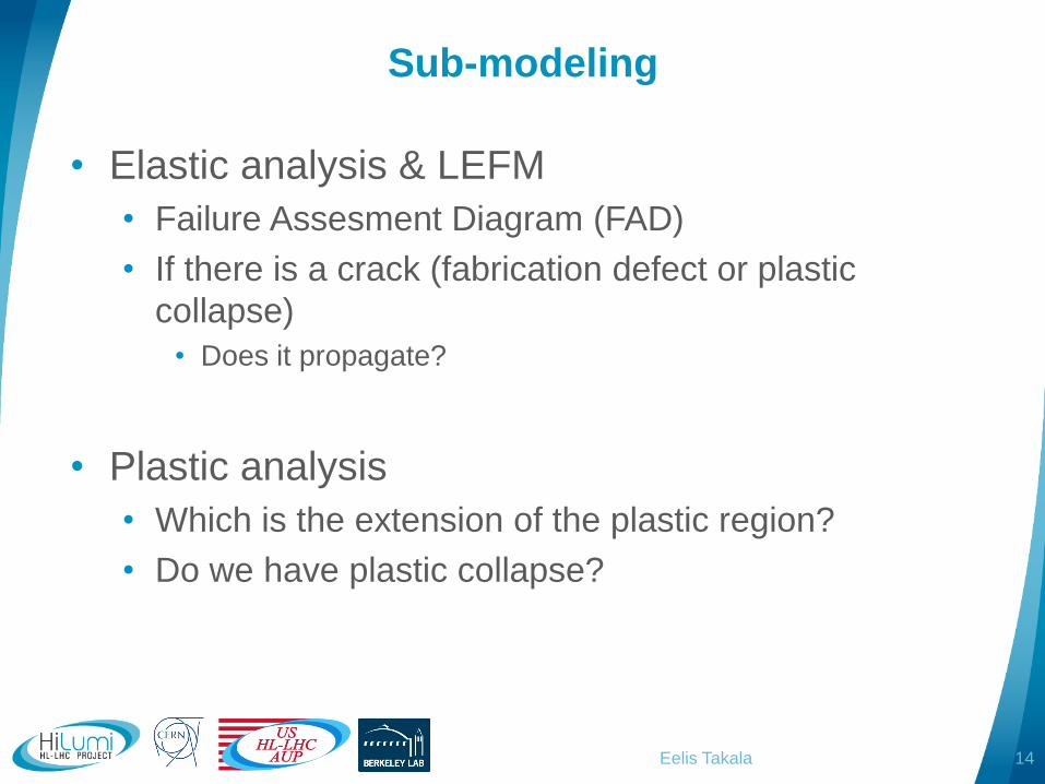
• Elastic analysis & LEFM
• Failure Assesment Diagram (FAD)
• If there is a crack (fabrication defect or plastic
collapse)
• Does it propagate?
• Plastic analysis
• Which is the extension of the plastic region?
• Do we have plastic collapse?
Eelis Takala 14
Failure assessment diagram paths
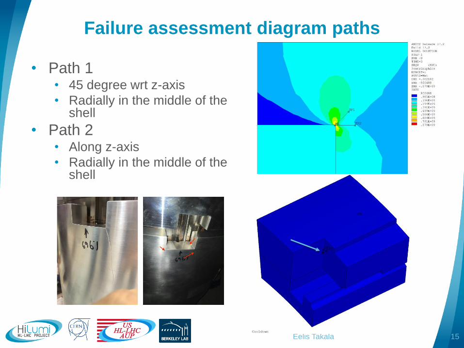
• Path 1• 45 degree wrt z-axis
• Radially in the middle of the shell
• Path 2• Along z-axis
• Radially in the middle of the shell
Eelis Takala 15

30°
70°
FAD diagram (LEFM)
Eelis Takala
𝐿
𝐿′≥ 1 ⇔ No Failure
𝐿
𝐿′< 1 ⇔ Failure
[1] E. Anderssen, S. Prestemon, “US HL-LHC Accelerator Upgrade Project Structural Design Criteria”, US-HiLumi-Doc-909
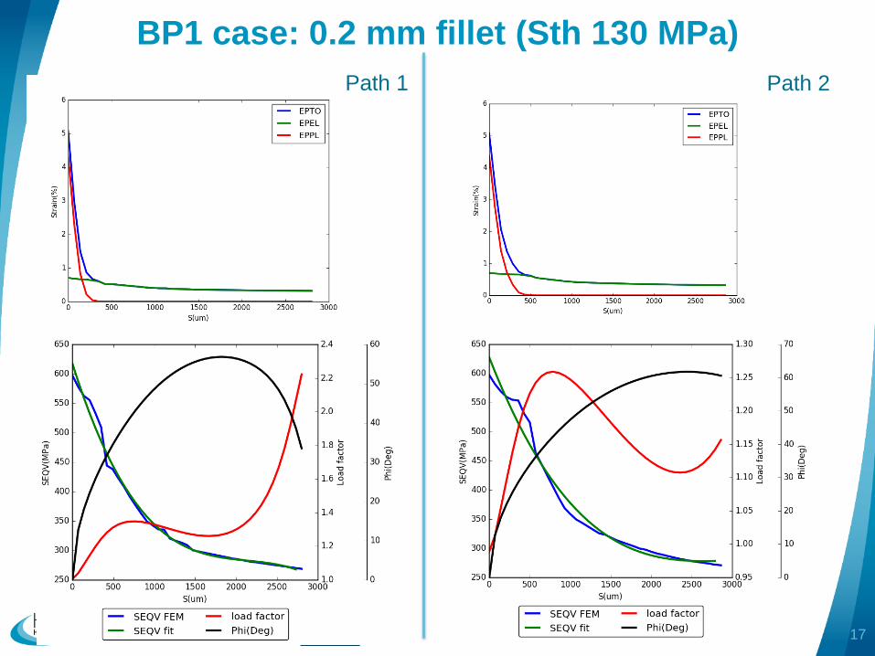
BP1 case: 0.2 mm fillet (Sth 130 MPa)
Eelis Takala 17
Path 2Path 1
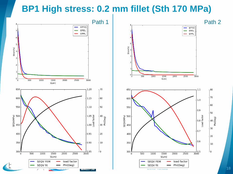
BP1 High stress: 0.2 mm fillet (Sth 170 MPa)
Eelis Takala 18
Path 2Path 1
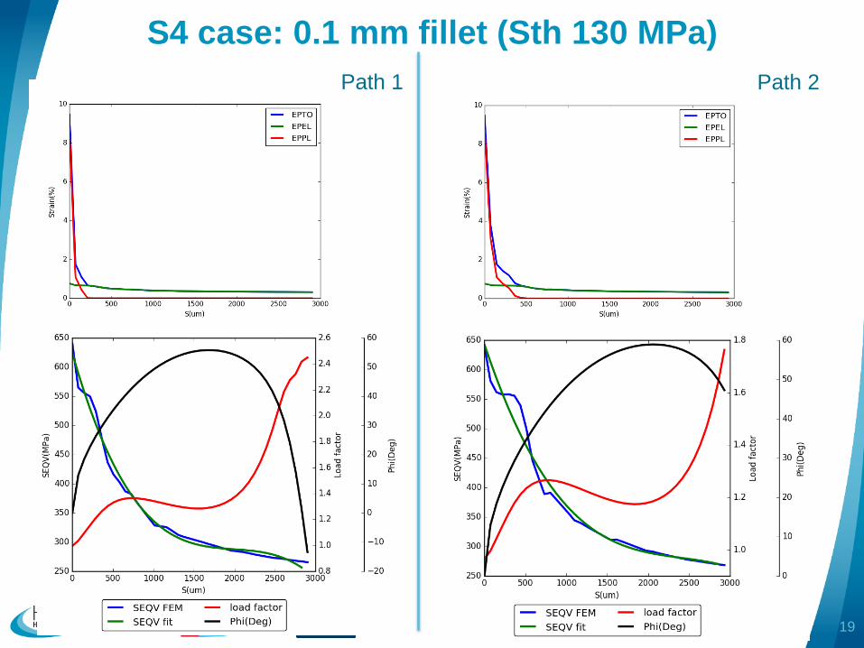
S4 case: 0.1 mm fillet (Sth 130 MPa)
Eelis Takala 19
Path 2Path 1

Summary of maximum strain
• Based on inter-/extrapolation of LBNL model results
• Agreement for BP1 and S4 cases between LBNL and CERN models
• Higher strain obtained for S5 CERN model
• BP1 should not exceed the limit elongation
• The solution obtained for AP1 and AP2 is not valid: the material fails
Eelis Takala 20
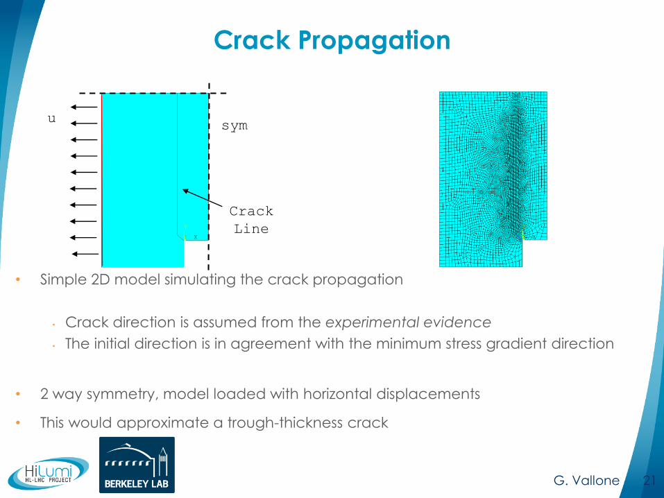
Crack Propagation
• Simple 2D model simulating the crack propagation
• Crack direction is assumed from the experimental evidence
• The initial direction is in agreement with the minimum stress gradient direction
• 2 way symmetry, model loaded with horizontal displacements
• This would approximate a trough-thickness crack
G. Vallone 21
usym
Crack
Line
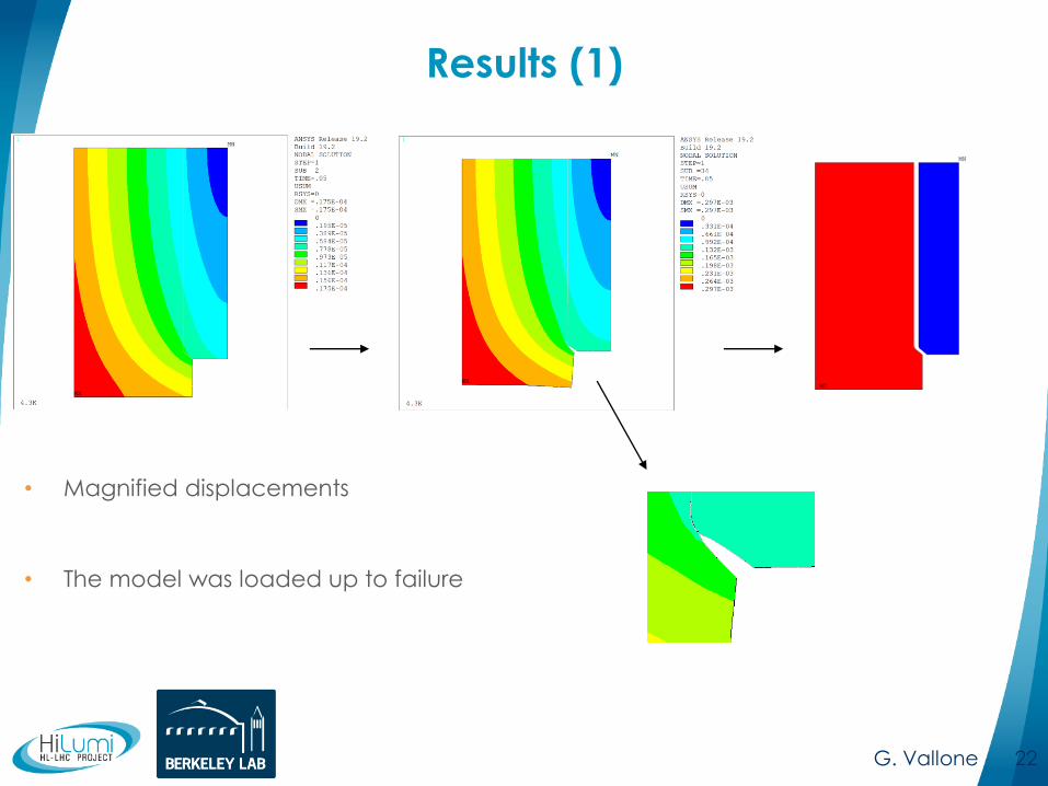
Results (1)
G. Vallone 22
• Magnified displacements
• The model was loaded up to failure

Proposed Design for the Weld Cutout
23
Proposed 15 mm cutout
path
• Stress level at the concentration location is expected
significant reduction if the fillet radius is as large as 15 mm.
• No plastic deformation in the results.

Eelis Takala 24
2 mm hole (Sth 130 MPa) 0.2 mm fillet (Sth 130 MPa)
BP1 case comparison
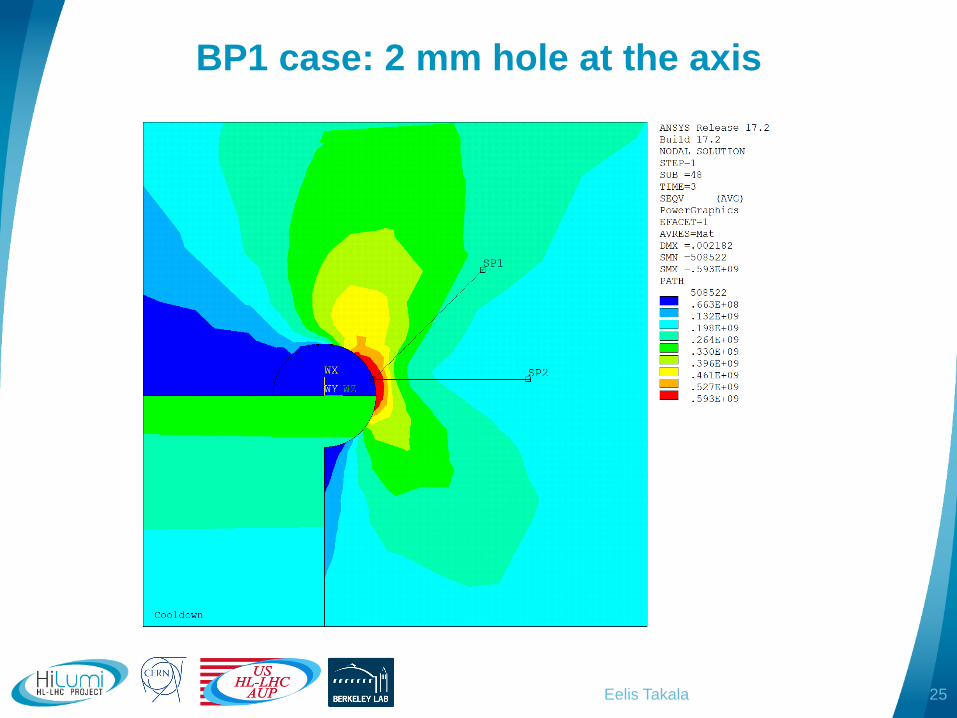
BP1 case: 2 mm hole at the axis
Eelis Takala 25

Eelis Takala 26
2 mm hole (Sth 130 MPa) 0.2 mm fillet (Sth 130 MPa)
BP1 case comparison
Path 1 Path 1
Path 2 Path 2

MQXFBP1 safety margin
• LBNL model
• Shell stress vs total strain
more or less linear
• CERN model
• 5% @ 130 MPa
• 7.5% @ 170 MPa
• 10% @ 210 Mpa?
=> Safety factor 1.6 in
terms of average shell
stress
Eelis Takala 27
LBNL models
Conclusions
• Analysis of the corner performed with elastic
and plastic sub-modeling
• General agreement between CERN and LBNL
models (S5 under inspection)
• According to the model BP1 has large margin
with respect to elongation to break and load
factor more than 1
• Lower strain and higher load factor than tested short
models
• Strain safety factor 1.6 in terms of average shell
stress
Eelis Takala 28
APPENDIX
Eelis Takala 29
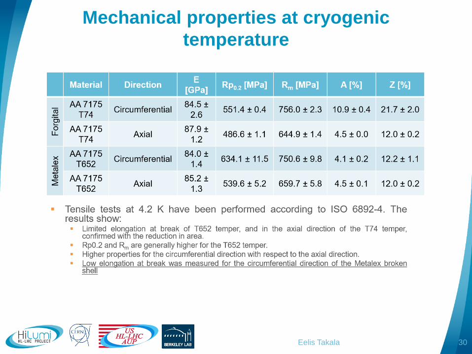
Mechanical properties at cryogenic
temperature
Eelis Takala 30
Fitting to elastic solution?
Eelis Takala 31
S5 0.1 mm fillet (Sth 181 MPa)
Eelis Takala 32
Path 2Path 1
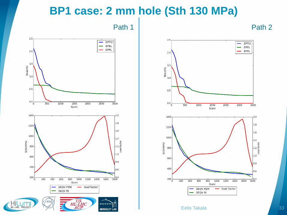
BP1 case: 2 mm hole (Sth 130 MPa)
Eelis Takala 33
Path 2Path 1
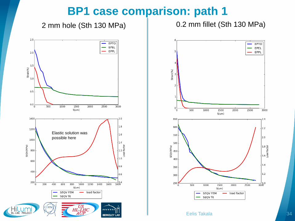
Eelis Takala 34
2 mm hole (Sth 130 MPa) 0.2 mm fillet (Sth 130 MPa)
BP1 case comparison: path 1
Elastic solution was
possible here
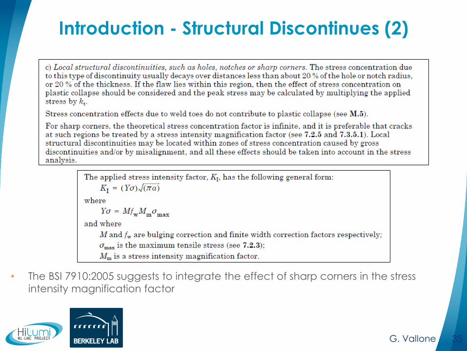
Introduction - Structural Discontinues (2)
• The BSI 7910:2005 suggests to integrate the effect of sharp corners in the stress
intensity magnification factor
G. Vallone 35


