76
MR-only Radiotherapy current status & perspectives Matteo Maspero [email protected] Postdoctoral researcher UMC Utrecht Center for Image Sciences Dep. Radiotherapy 12 th October 2018

MR-only Radiotherapycurrent status & perspectives
Matteo Maspero [email protected] researcher
UMC Utrecht Center for Image Sciences
Dep. Radiotherapy 12th October 2018
necessary to ensure a safe clinical implementation of an MR-only pathway into the clinic.

Content
1. Introduction
• Definition & requirements, rationale
2. The challenges
• MRI for treatment simulation
• Dose accuracy
• Position verification
3. World-wide diffusion: where are we standing?
4. Perspective: what is it rising at the horizon?
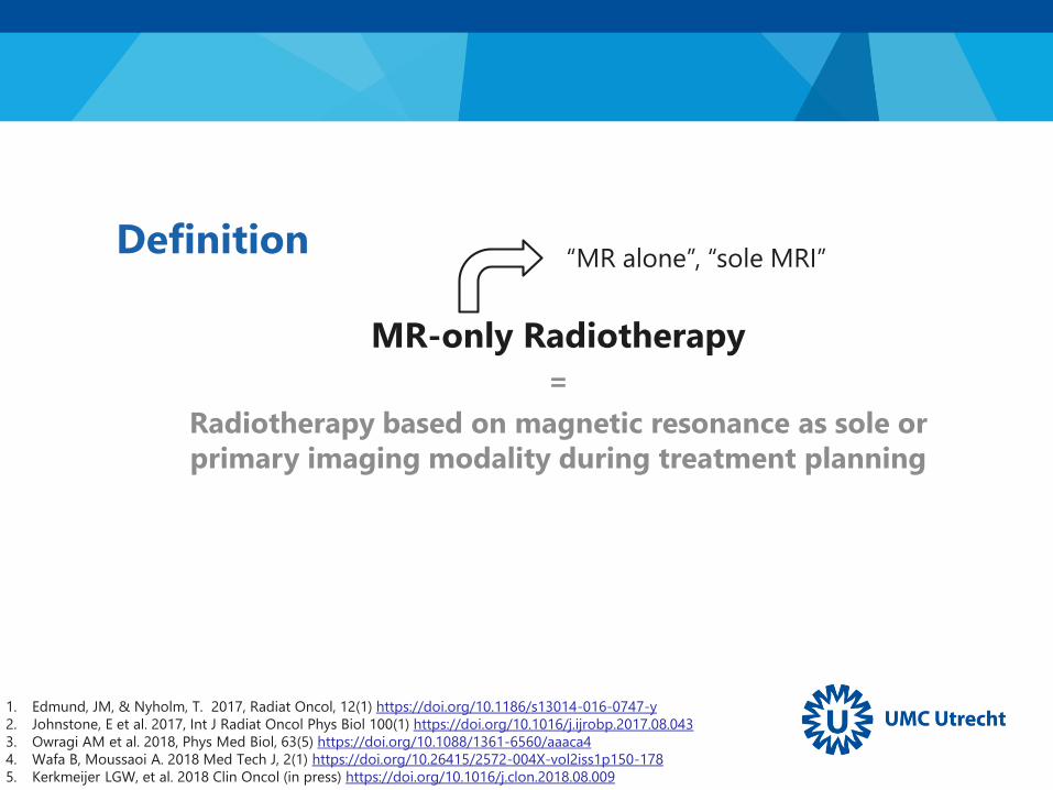
Definition
MR-only Radiotherapy
=
Radiotherapy based on magnetic resonance as sole or
primary imaging modality during treatment planning
“MR alone”, “sole MRI”
1. Edmund, JM, & Nyholm, T. 2017, Radiat Oncol, 12(1) https://doi.org/10.1186/s13014-016-0747-y
2. Johnstone, E et al. 2017, Int J Radiat Oncol Phys Biol 100(1) https://doi.org/10.1016/j.ijrobp.2017.08.043
3. Owragi AM et al. 2018, Phys Med Biol, 63(5) https://doi.org/10.1088/1361-6560/aaaca4
4. Wafa B, Moussaoi A. 2018 Med Tech J, 2(1) https://doi.org/10.26415/2572-004X-vol2iss1p150-178
5. Kerkmeijer LGW, et al. 2018 Clin Oncol (in press) https://doi.org/10.1016/j.clon.2018.08.009
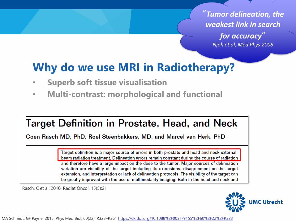
Why do we use MRI in Radiotherapy?
• Superb soft tissue visualisation
• Multi-contrast: morphological and functional
MA Schmidt, GF Payne. 2015, Phys Med Biol, 60(22): R323–R361 https://dx.doi.org/10.1088%2F0031-9155%2F60%2F22%2FR323
Rasch, C et al. 2010 Radiat Oncol, 15(5):21
“Tumor delineation, the
weakest link in search
for accuracy”Njeh et al, Med Phys 2008

Why do we use MRI in Radiotherapy?
MA Schmidt, GF Payne. 2015, Phys Med Biol, 60(22): R323–R361 https://dx.doi.org/10.1088%2F0031-9155%2F60%2F22%2FR323
A visual demonstration…

CT vs MR: Prostate
• Prostate anatomy is not well visualized on CT and it can be difficult to
delineate prostate from rectum.
• MRI is helpful for visualization of prostate anatomy and tumor
CT MRI – T1w 3D GRE MRI – 3D bTFE fat sup
Chandarana H et al. 2018 J Magn Reson Imaging https://doi.org/10.1002/jmri.26271

CT vs MR: Head & Neck
T2N2b hypopharynx tumour
Contrast Enhanced-CT MRI – T1w Gd
Head-neck tumor are contoured on MRI and routinely fused with CT
Chandarana H et al. 2018 J Magn Reson Imaging https://doi.org/10.1002/jmri.26271
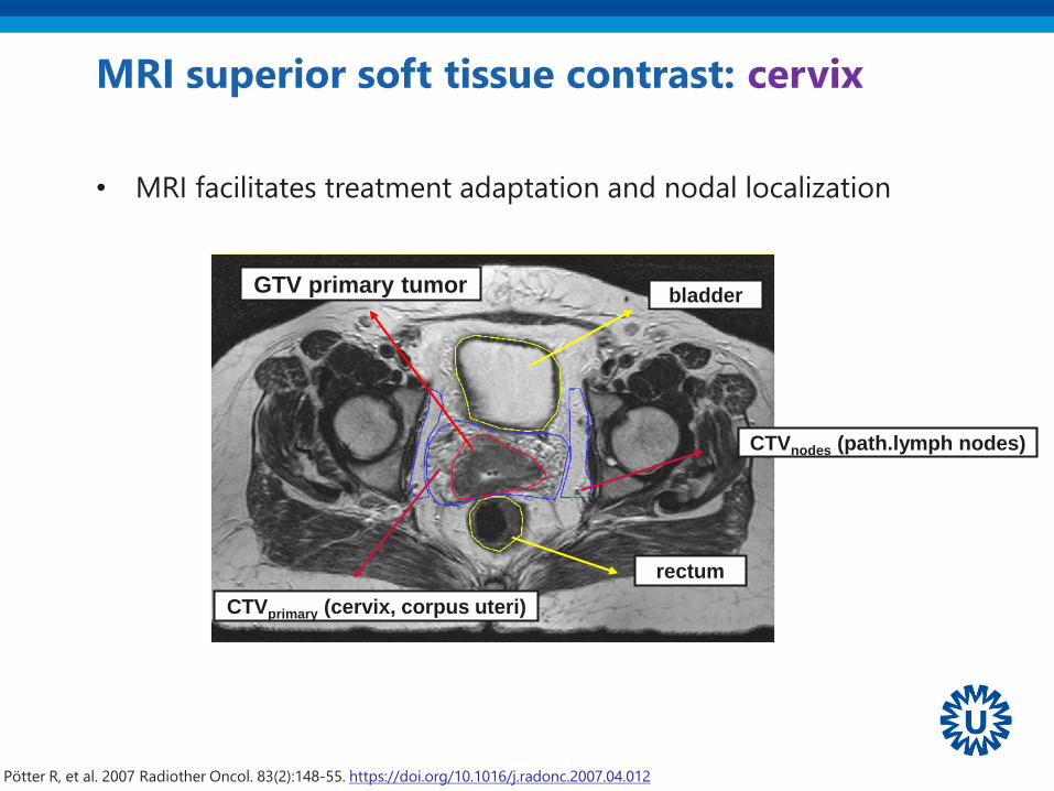
MRI superior soft tissue contrast: cervix
GTV primary tumor
rectum
bladder
CTVprimary (cervix, corpus uteri)
Pötter R, et al. 2007 Radiother Oncol. 83(2):148-55. https://doi.org/10.1016/j.radonc.2007.04.012
• MRI facilitates treatment adaptation and nodal localization
CTVnodes (path.lymph nodes)
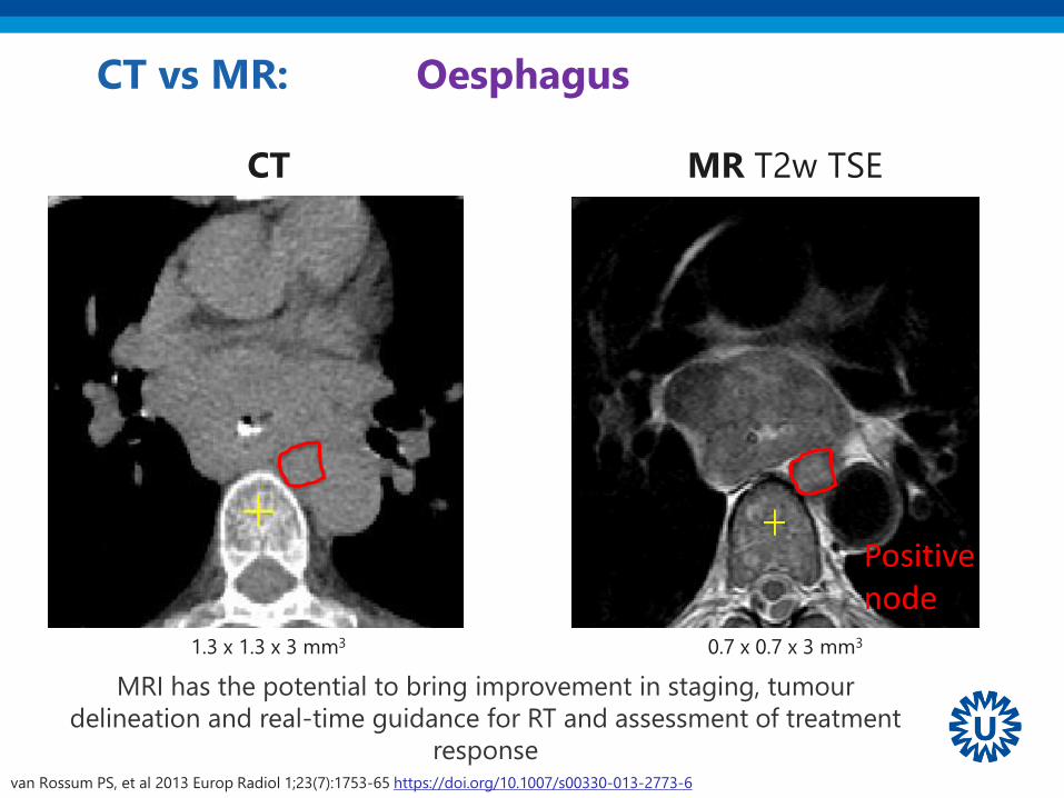
CT vs MR: Oesphagus
CT
1.3 x 1.3 x 3 mm3 0.7 x 0.7 x 3 mm3
MR T2w TSE
van Rossum PS, et al 2013 Europ Radiol 1;23(7):1753-65 https://doi.org/10.1007/s00330-013-2773-6
MRI has the potential to bring improvement in staging, tumour
delineation and real-time guidance for RT and assessment of treatment
response
Positive node
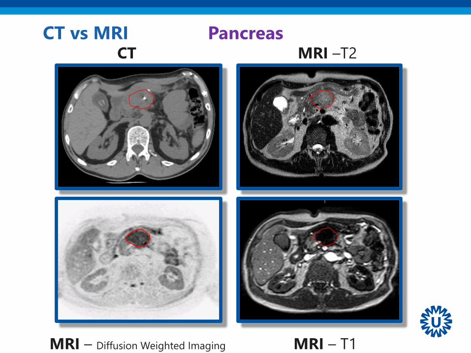
CT MRI –T2
MRI – T1MRI – Diffusion Weighted Imaging
CT vs MRI Pancreas
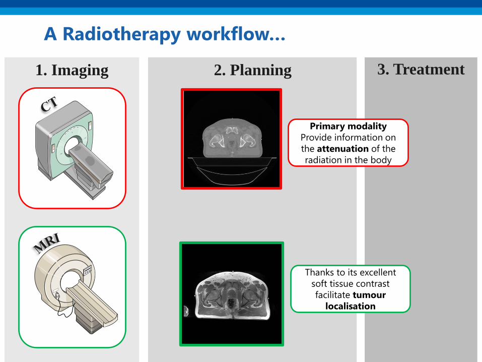
2. Planning 3. Treatment1. Imaging
A Radiotherapy workflow…
Primary modality
Provide information on
the attenuation of the
radiation in the body
Thanks to its excellent
soft tissue contrast
facilitate tumour
localisation
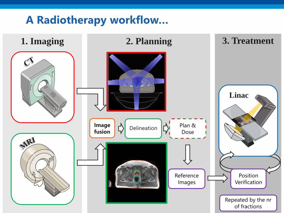
2. Planning 3. Treatment1. Imaging
A Radiotherapy workflow…
Image
fusion
Reference
Images
Plan &
DoseDelineation
Linac
Position
Verification
Repeated by the nr
of fractions

2. Planning 3. Treatment1. Imaging
An MR-only Radiotherapy workflow
Image
fusion
Reference
Images
Plan &
DoseDelineation
Linac
Position
Verification
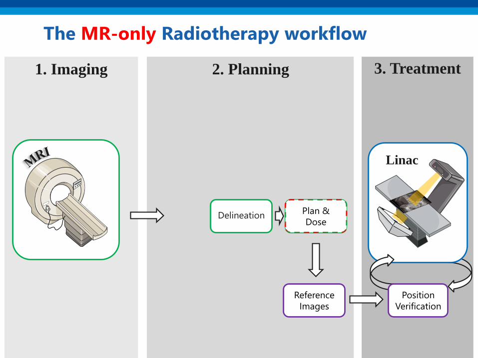
2. Planning
Plan &
Dose
3. Treatment1. Imaging
The MR-only Radiotherapy workflow
Reference
Images
Plan &
DoseDelineation
Linac
Position
Verification
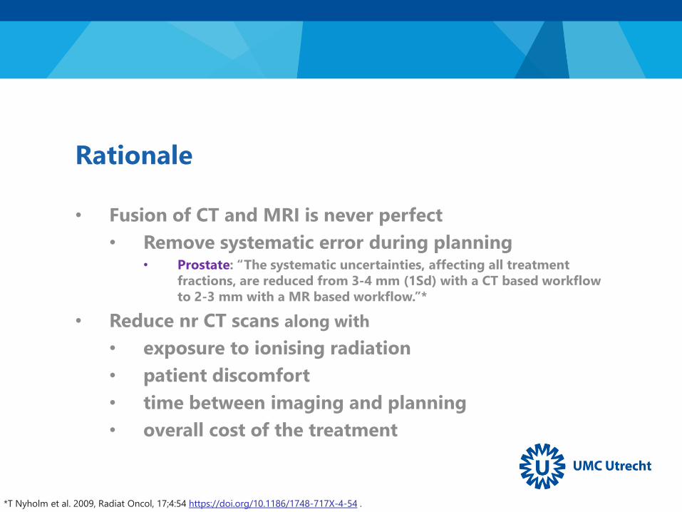
Rationale
• Fusion of CT and MRI is never perfect
• Remove systematic error during planning• Prostate: “The systematic uncertainties, affecting all treatment
fractions, are reduced from 3-4 mm (1Sd) with a CT based workflow
to 2-3 mm with a MR based workflow.”*
• Reduce nr CT scans along with
• exposure to ionising radiation
• patient discomfort
• time between imaging and planning
• overall cost of the treatment
*T Nyholm et al. 2009, Radiat Oncol, 17;4:54 https://doi.org/10.1186/1748-717X-4-54 .
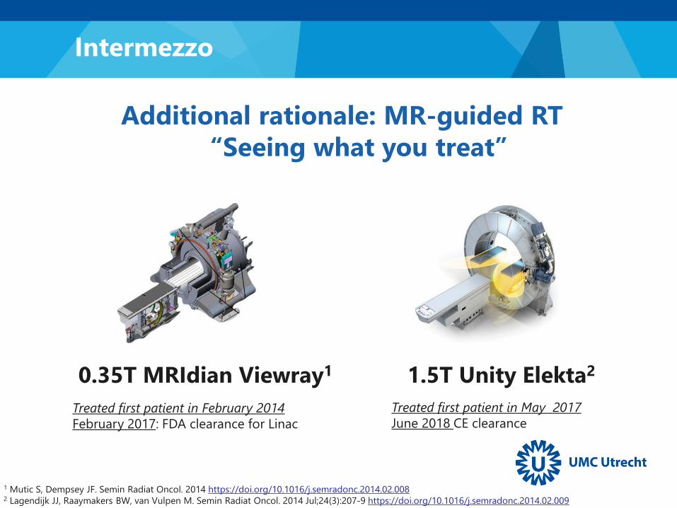
Treated first patient in February 2014
February 2017: FDA clearance for Linac
Additional rationale: MR-guided RT
“Seeing what you treat”
1 Mutic S, Dempsey JF. Semin Radiat Oncol. 2014 https://doi.org/10.1016/j.semradonc.2014.02.0082 Lagendijk JJ, Raaymakers BW, van Vulpen M. Semin Radiat Oncol. 2014 Jul;24(3):207-9 https://doi.org/10.1016/j.semradonc.2014.02.009
1.5T Unity Elekta20.35T MRIdian Viewray1
Treated first patient in May 2017
June 2018 CE clearance
Intermezzo
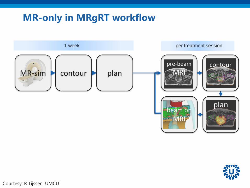
plan
pre-beam
MRI
beam on
MRI
contourMR-sim plan
1 week per treatment session
contour
MR-only in MRgRT workflow
Courtesy: R Tijssen, UMCU

A clarifying intermezzo
MR-only
RT
MR-guided
RT
MR-based
Dose calculation &
Position Verification
PET-MRI*
Hofmann, M et al. 2009, Eur J Nucl Med Mol Imaging 36(1): 93
MR-based
Attenuation
Correction
The challenges
1) MR for treatment simulation
2) MR-based dose calculations
3) MRI as reference images for position verification

MRI for treatment
simulation1

➢ MRI is generally seen as a diagnostic tool, but..
➢ MRI in radiotherapy ≠ MRI in radiology
➢ Need to re-optimise exam card
➢ Geometric accuracy
➢ Large field of view (FOV)
➢ Hardware and software adaptation to accommodate
o RT positioning
MRI for treatment simulation
McWilliam A, et al. 2018 Clin Oncol 30(11):680-685 https://doi.org/10.1016/j.clon.2018.08.004
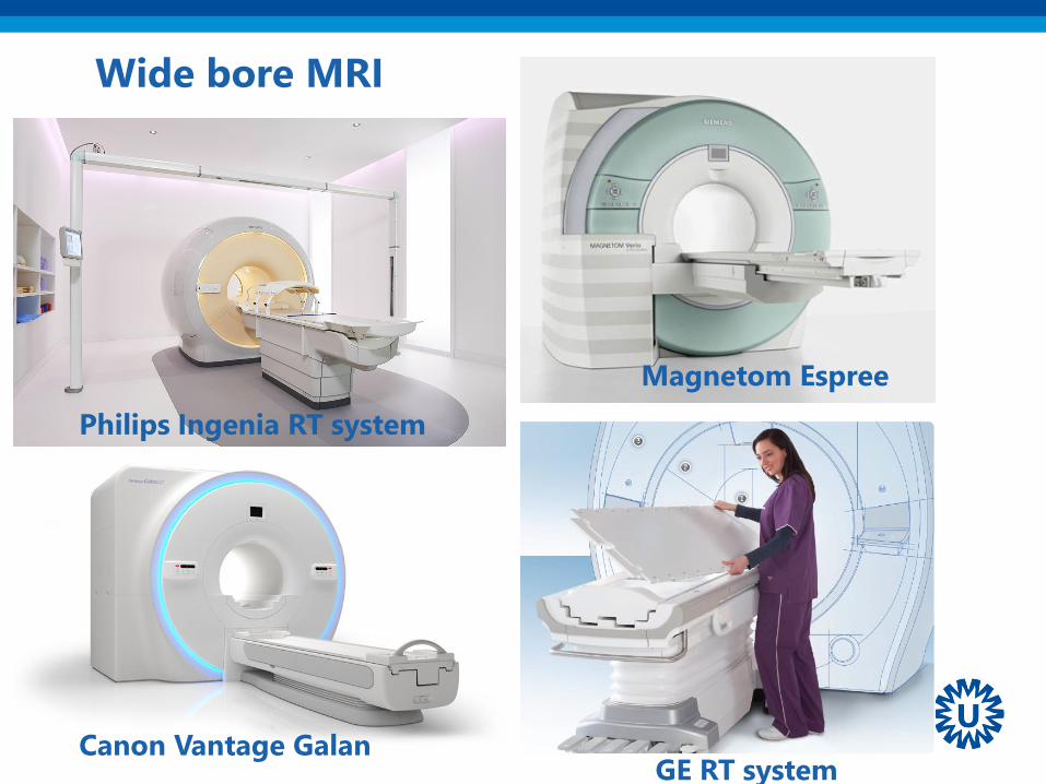
Wide bore MRI
Magnetom Espree
GE RT system
Philips Ingenia RT system
Canon Vantage Galan
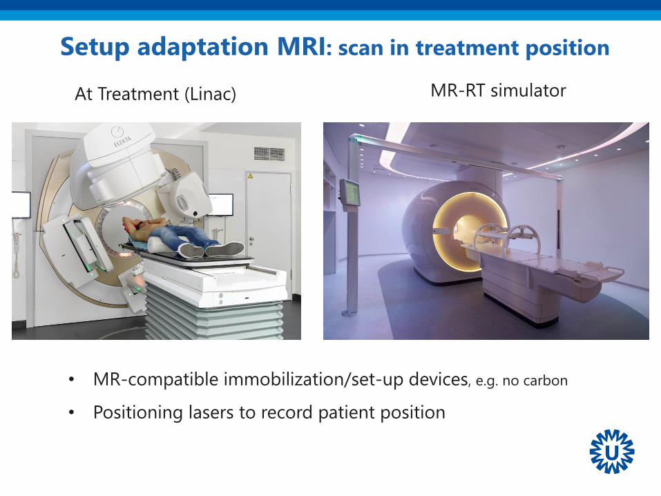
Setup adaptation MRI: scan in treatment position
MR-RT simulator At Treatment (Linac)
• MR-compatible immobilization/set-up devices, e.g. no carbon
• Positioning lasers to record patient position

Adaptations imaging in treatment position
flat table-top
Flat table top instead of
Concave MR diagnostic table top
Coil bridge not deform body contour
A crucial aspect: Geometric Fidelity
Characterization, prediction, and correction of geometric distortion in 3T MR images
Baldwin, Lesley N. and Wachowicz, Keith and Thomas, Steven D. and Rivest, Ryan and
Fallone, B. Gino, Medical Physics, 34, 388-399 (2007)
“Armed with detailed knowledge of spatial distortion, MR images can be undistorted…”
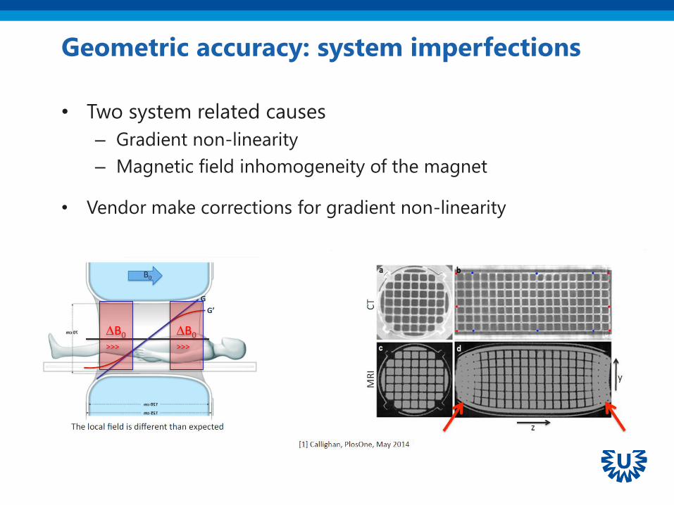
Geometric accuracy: system imperfections
• Two system related causes
– Gradient non-linearity
– Magnetic field inhomogeneity of the magnet
• Vendor make corrections for gradient non-linearity
B0
>>>
B0
>>>
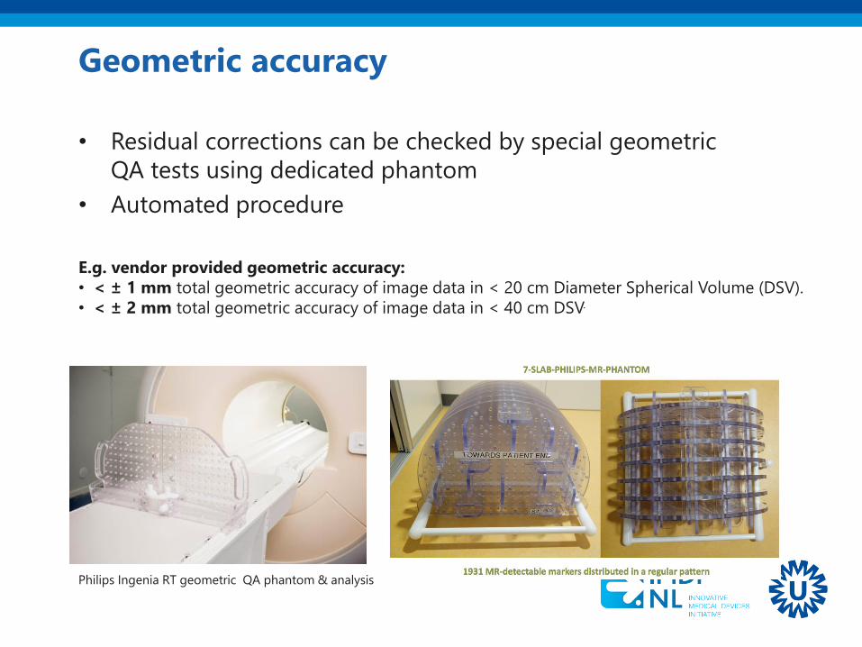
Geometric accuracy
• Residual corrections can be checked by special geometric
QA tests using dedicated phantom
• Automated procedure
Philips Ingenia RT geometric QA phantom & analysis
E.g. vendor provided geometric accuracy:
• < ± 1 mm total geometric accuracy of image data in < 20 cm Diameter Spherical Volume (DSV).
• < ± 2 mm total geometric accuracy of image data in < 40 cm DSV.

Patient induced magnetic field distortions
• Regions with transitions in magnetic susceptibility
causes magnetic field distortions.
5.8 ppm
-4.0 ppm
2.0 ppm
How to mitigate B0 distortions: high bandwidth
Which is the price? Decrease of signal-to-noise ratio
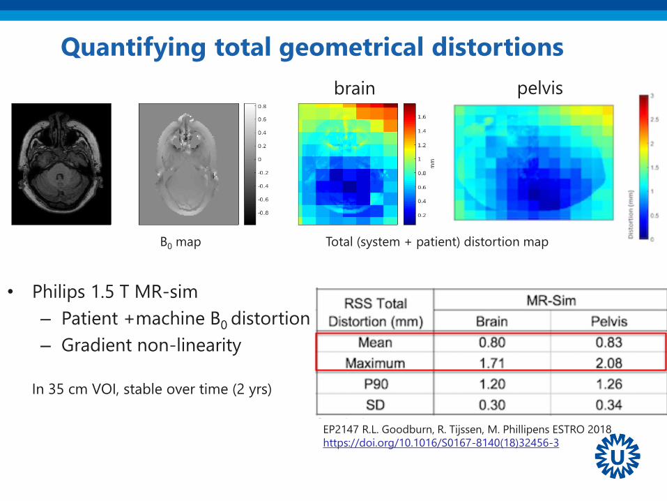
Quantifying total geometrical distortions
EP2147 R.L. Goodburn, R. Tijssen, M. Phillipens ESTRO 2018
https://doi.org/10.1016/S0167-8140(18)32456-3
Total (system + patient) distortion mapB0 map
pelvisbrain
• Philips 1.5 T MR-sim
– Patient +machine B0 distortion
– Gradient non-linearity
In 35 cm VOI, stable over time (2 yrs)
MRI for treatment
simulation1• Adaptations are necessary but possible
• Vendors have seen the potential of MRI in RT and
facilitate MR simulation
• MRI expertise is needed
MR-based dose
calculations2
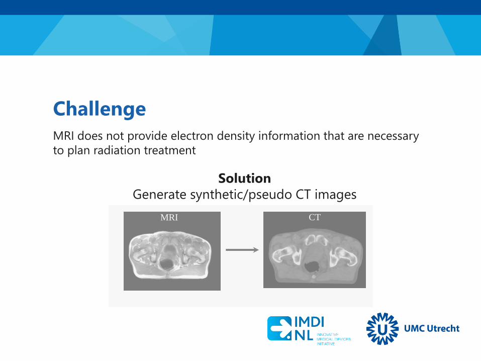
Solution
Generate synthetic/pseudo CT images
MRI CT
Challenge
MRI does not provide electron density information that are necessary
to plan radiation treatment

Approaches so far proposed: in numbers
• Meeting point with MR-PET
• Voxel-based
• Atlas
• Hybrid
Brain/H&N
Prostate
TorsoPhantom
75.3%
12.4%
7.4%
Pu
bli
cati
on
s RT
MR/PET
Both
1998 2004 2006 2007 2008 2010 2011 2012 2013 2014 2015
Vandenberghe, S and Mardsen PK, 2015, Phys Med Biol 60:R115
Until 2015 ~ 50 papers (RT only)
Edmund, JM, & Nyholm, T. 2017, Radiat Oncol, 12(1) https://doi.org/10.1186/s13014-016-0747-y
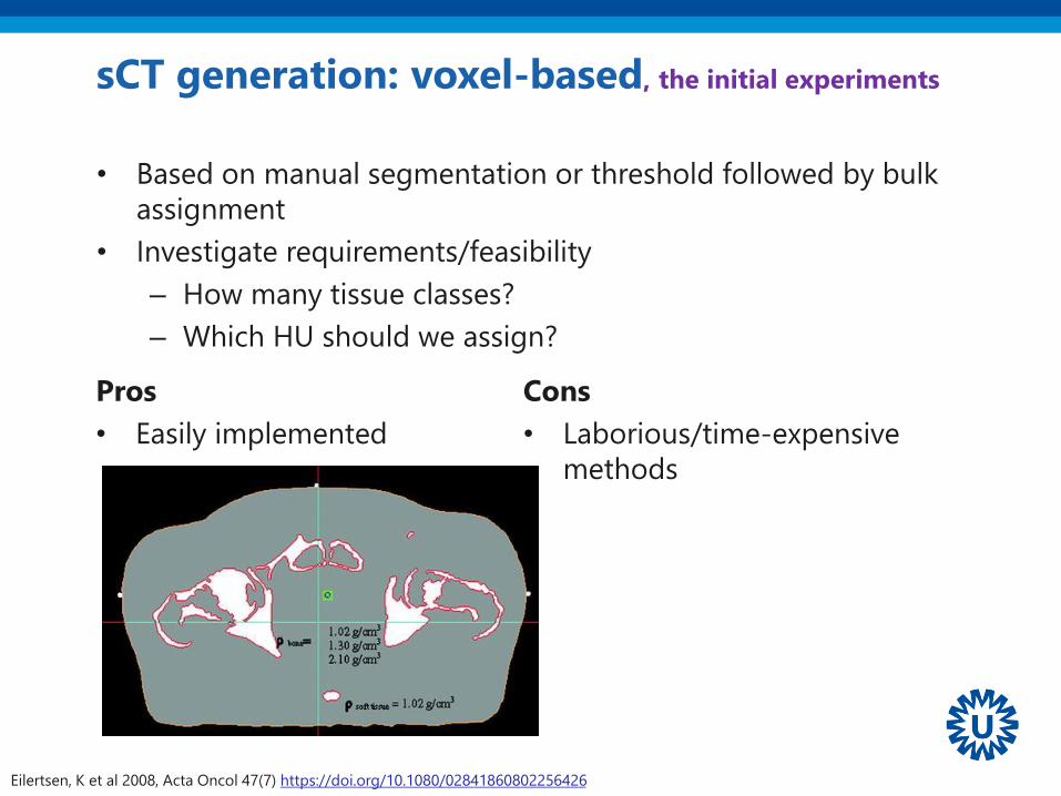
sCT generation: voxel-based, the initial experiments
• Based on manual segmentation or threshold followed by bulk
assignment
• Investigate requirements/feasibility
– How many tissue classes?
– Which HU should we assign?
Eilertsen, K et al 2008, Acta Oncol 47(7) https://doi.org/10.1080/02841860802256426
Pros
• Easily implemented
Cons
• Laborious/time-expensive
methods

sCT generation: voxel-based, regression
Nyholm, T, Jonsson, J. 2014 Sem Radiat Oncol, 24(3) https://doi.org/10.1016/j.semradonc.2014.02.005
Gaussian regression to map MRI
voxel into CT voxel
• Use non-standard sequence to
facilitate the regression
Pros
• Fast, more
elegant
Cons
• Robustness can
require non-
standard MR
sequences

sCT generation: atlas
Jens Sjölund et al, 2015. Phys Med Biol, 60(2). http://dx.doi.org/10.1088/0031-9155/60/2/825
Dowling JA et al. 2012 Int J Radiat Oncol Biol Phys 83(1) https://doi.org/10.1016/j.ijrobp.2011.11.056
Pros
• Robust methods, given the a-
priori knowledge that an
atlas incorporate
Cons
• A-priori knowledge does not
deal with abnormal
anatomies
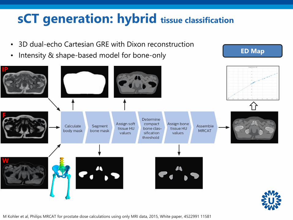
• 3D dual-echo Cartesian GRE with Dixon reconstruction
• Intensity & shape-based model for bone-only
sCT generation: hybrid tissue classification
ED Map
W
IP
F
M Kohler et al, Philips MRCAT for prostate dose calculations using only MRI data, 2015, White paper, 4522991 11581

• MRCAT, Philips Healthcare
– prostate
– CE and FDA approved on 2016-03-21 http://goo.gl/jtyX8H
• MriPlanner, Spectronic Medical AB
– prostate
– CE approved pending 2016-06-16 https://goo.gl/cY5Zrn
• Syngo.via.syntheticCT, SIEMENS
– Vendor specific platform for translational research
– brain
– CE FDA approved from 2018-01-12 https://goo.gl/37vEv6
Approaches so far proposed: commercial solutions

How to check the dose accuracy
MRI
CTsCT
Treatment Planning System
sCT
DoseCT
Dose
Rigid
Registration
Image and dose comparison
MR
-deriv
edC
T-d
eri
ved
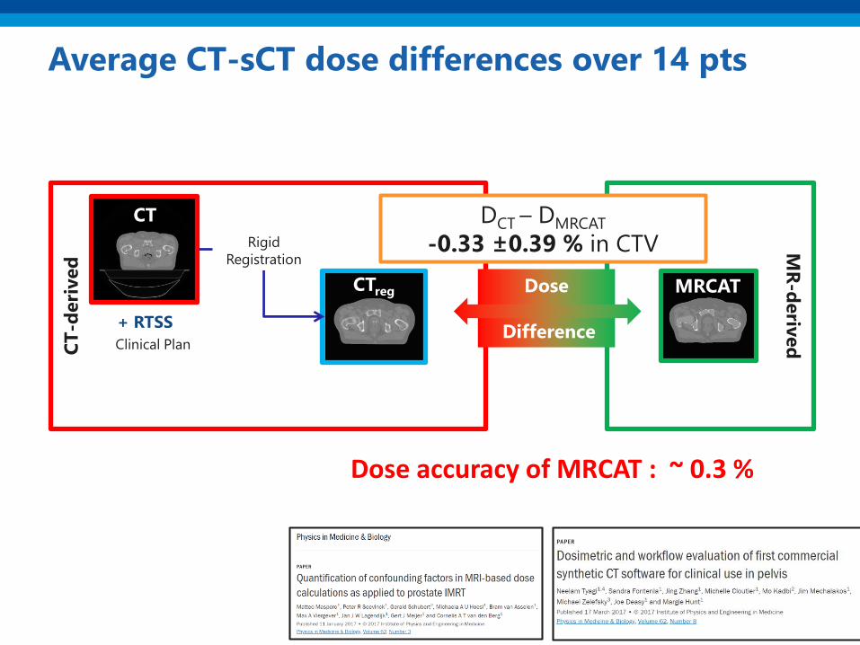
Average CT-sCT dose differences over 14 pts
+ RTSS
MRCATCTreg
Rigid
Registration
Clinical Plan
CT
Dose
Difference
DCT – DMRCAT
-0.33 ±0.39 % in CTV
Dose accuracy of MRCAT : ~ 0.3 %

sCT generation: dose accuracy, e.g. prostate
Kerkmeijer LGW et al. 2018 Clin Oncol (in press) https://doi.org/10.1016/j.clon.2018.08.009;
Maspero M. 2018, ISNB: 978-90-393-6953-1 https://dspace.library.uu.nl/handle/1874/362987.
Dose differences < 1% between CT and MR-based dose calculations
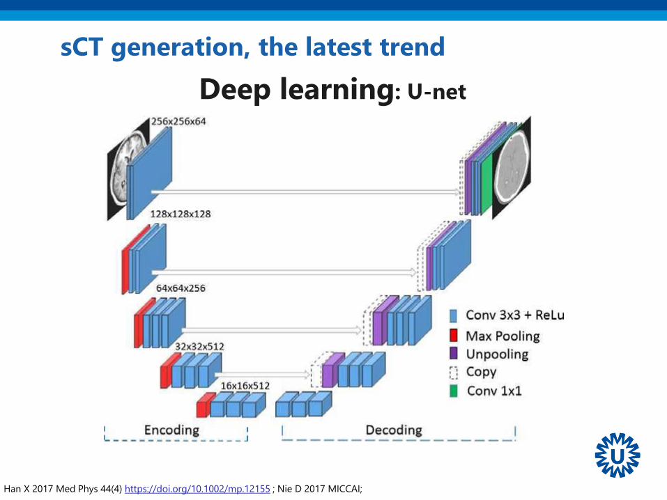
sCT generation, the latest trend
Han X 2017 Med Phys 44(4) https://doi.org/10.1002/mp.12155 ; Nie D 2017 MICCAI;
Deep learning: U-net
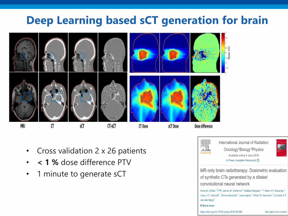
Deep Learning based sCT generation for brain
• Cross validation 2 x 26 patients
• < 1 % dose difference PTV
• 1 minute to generate sCT

Deep Learning based sCT generation for pelvis
Maspero et al. 2018, Phys Med Biol 63(18):185001 https://doi.org/10.1088/1361-6560/aada6d
pix2pix
500
-500
HU
MRICT sCT
Dose differences in target/OAR < 0.5%
Pros
• Do not require non-standard
sequence
• No need of a deterministic
image processing pipeline
• Cons
• Steep learning curve to start
working with these methods
• Need of GPU

MR-based
attenuation
correction2
• For brain and prostate, sCT generation seem to be a
solved problem
• Commercial solutions are available and can facilitate
the implementation

MRI as reference for
position verification3

Image guided dose delivery
Cone beam CT, or EPID
• Patient anatomy aligned to radiation
beam by registration of daily CBCT
to planning CT = reference
• Provides translation and rotation of
patient table
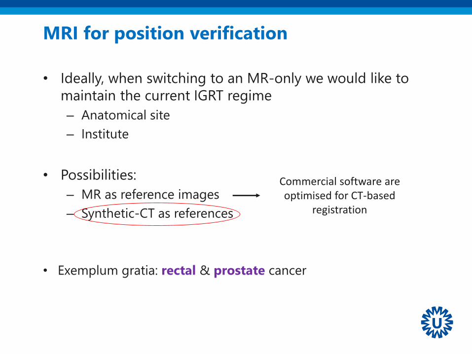
MRI for position verification
• Ideally, when switching to an MR-only we would like to
maintain the current IGRT regime
– Anatomical site
– Institute
• Possibilities:
– MR as reference images
– Synthetic-CT as references
• Exemplum gratia: rectal & prostate cancer
Commercial software are optimised for CT-based
registration

Position verification for rectal cancer @ UMCU
De Boer HCJ and Heijmen BJM, 2007, Int J Radiat Oncol Biol Phys 67(5):1586-95
Match
based on
CBCT on
bones in a
clipbox
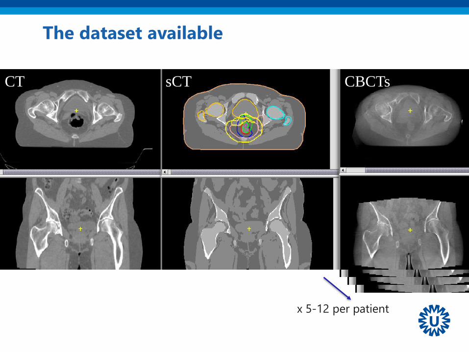
The dataset available
CT sCT CBCTs
x 5-12 per patient
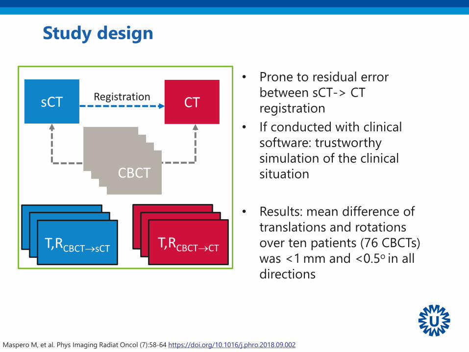
• Prone to residual error
between sCT-> CT
registration
• If conducted with clinical
software: trustworthy
simulation of the clinical
situation
• Results: mean difference of
translations and rotations
over ten patients (76 CBCTs)
was <1 mm and <0.5o in all
directions
Study design
CTsCT
T,RCBCT→sCT
Registration
CBCT
T,RCBCT→CT
CBCTCBCTCBCT
T,RCBCT→sCTT,RCBCT→sCTT,RCBCT→CTT,RCBCT→CT
Maspero M, et al. Phys Imaging Radiat Oncol (7):58-64 https://doi.org/10.1016/j.phro.2018.09.002
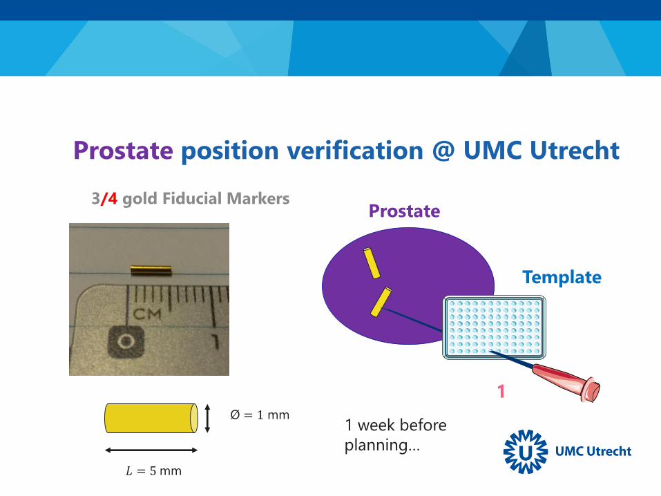
3/4 gold Fiducial Markers
Template
Prostate
1
𝐿 = 5 mm
Ø = 1 mm
Prostate position verification @ UMC Utrecht
1 week before
planning…
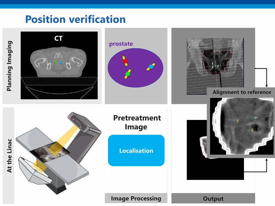
OutputImage Processing
At
the L
inac
Pla
nn
ing
Im
ag
ing
Position verification
CT
Localisation
prostate
Alignment to reference
PretreatmentImage
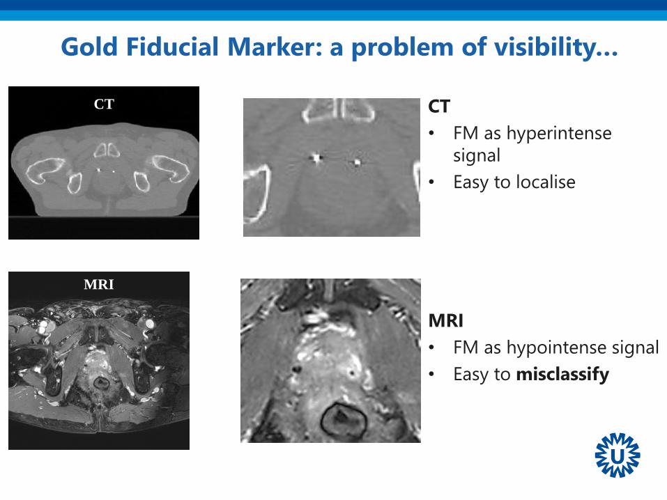
Gold Fiducial Marker: a problem of visibility…
CT
• FM as hyperintense
signal
• Easy to localise
MRI
• FM as hypointense signal
• Easy to misclassify
MRI
CT

bSSFP fatsat Multi echo GRE
CT
Inter-observer study to locate the fiducials
• 5 RTT
• 17 patients with each 3 fiducials
• 2 MRI sequences (one locate)
Maspero M et al. 2018 Radiat Oncol 5;13(1):105. https://doi.org/10.1186/s13014-018-1029-7
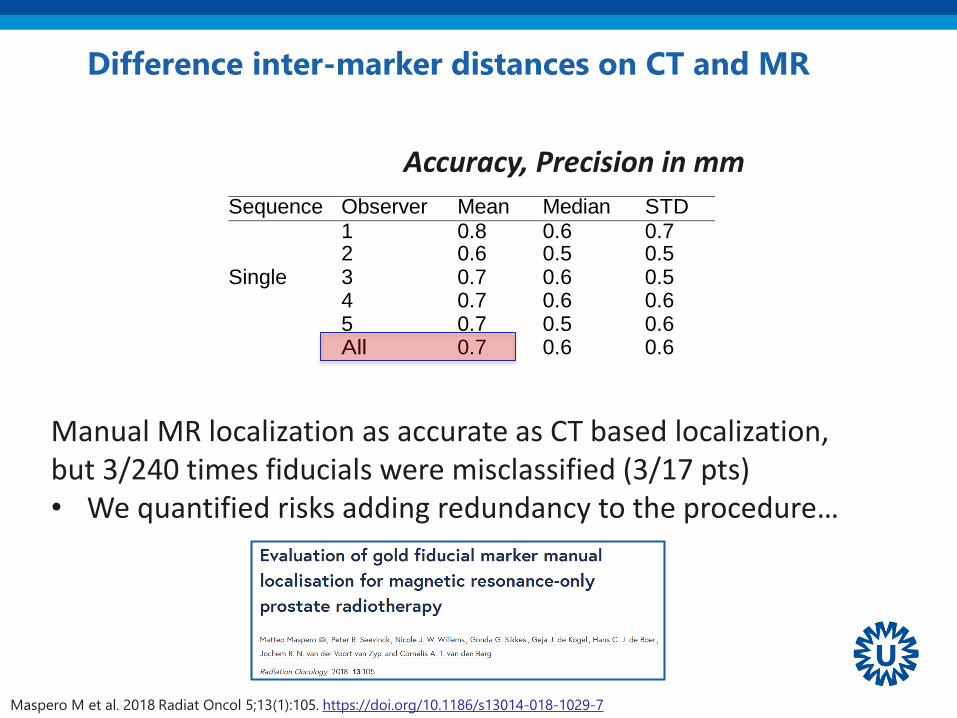
Difference inter-marker distances on CT and MR
Sequence Observer Mean Median STD Range
1 0.8 0.6 0.7 [0.1, 3.1]
2 0.6 0.5 0.5 [0.0, 2.5] Single 3 0.7 0.6 0.5 [0.0, 2.1]
4 0.7 0.6 0.6 [0.1, 2.9]
5 0.7 0.5 0.6 [0.1, 2.5]
All 0.7 0.6 0.6 [0.0, 3.1]
1 0.7 0.4 0.6 [0.0, 2.7]
2 0.6 0.4 0.6 [0.0, 3.0] Multiple 3 0.7 0.5 0.7 [0.0, 2.5]
4 0.7 0.5 0.6 [0.0, 2.8]
5 0.7 0.6 0.5 [0.0, 2.5]
All 0.6 0.5 0.6 [0.0, 3.0]
Accuracy, Precision in mm
Manual MR localization as accurate as CT based localization,but 3/240 times fiducials were misclassified (3/17 pts)• We quantified risks adding redundancy to the procedure…
Maspero M et al. 2018 Radiat Oncol 5;13(1):105. https://doi.org/10.1186/s13014-018-1029-7
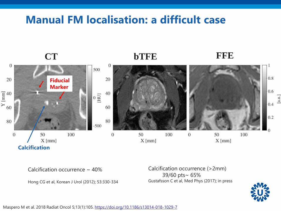
Manual FM localisation: a difficult case
Calcification
Fiducial
Marker
Calcification occurrence ~ 40%
Hong CG et al, Korean J Urol (2012); 53:330-334
Calcification occurrence (>2mm)
39/60 pts~ 65%Gustafsson C et al, Med Phys (2017); in press
CT bTFE FFE
Maspero M et al. 2018 Radiat Oncol 5;13(1):105. https://doi.org/10.1186/s13014-018-1029-7

Manual FM localisation: a difficult case
1/3 FM has 1/5 observer in disagreement
FM 2
Maspero M et al. 2018 Radiat Oncol 5;13(1):105. https://doi.org/10.1186/s13014-018-1029-7

Automatic methods to localize fiducials
Maspero M et al Phys Med Biol. 2017 Oct 3;62(20):7981-
8002 https://doi.org/10.1088/1361-6560/aa875f
Gustafsson C et al. Med Phys 2017;44(11):5563-5574.
https://doi.org/10.1002/mp.12516
Ghose S et al. Med Phys 2016;43(5):2218
https://doi.org/10.1118/1.4944871
Fernandes C et al. PHIRO 2017;1:14-20
https://doi.org/10.1016/j.phro.2017.02.001
Up to ~98% accurate FM classification with
automatic method
Maspero, M. 2018, PhD Thesis, ISBN: 978-90-393-6953-1
https://dspace.library.uu.nl/handle/1874/362987

MRI as reference for
position verification3• MRI-based position verification is feasible
• No general recipe: every clinic should verify according
to its IGRT standard

+1
3Workflow
adaptation
for clinical
introduction

Clinical introduction: simulation is a complex serial workflow
Multi-vendor workflow documentation
QA testing?Data flowSoftware adaptations
MRI RTT image processing unit
Radiationoncologist
Planning Position verification
trainingWork instructions
protocollogistics

4Diffusion of
MR-only RT
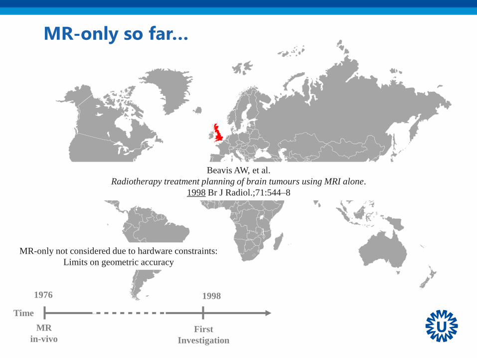
Time
MR-only so far…
1976
MR
in-vivo
1998
First
Investigation
Beavis AW, et al.
Radiotherapy treatment planning of brain tumours using MRI alone.
1998 Br J Radiol.;71:544–8
MR-only not considered due to hardware constraints:
Limits on geometric accuracy

Time
MR-only so far…
1976
MR
in-vivoInitial
Investigations
sCT
generationFeasibility
Edmund, JM & Nyholm, T.
2017, Radiat Oncol, 12(1):28
Pu
bli
cati
on
s RT
MR/PET
Both
1998 2004 2006 2007 2008 2010 2011 2012 2013 2014 2015
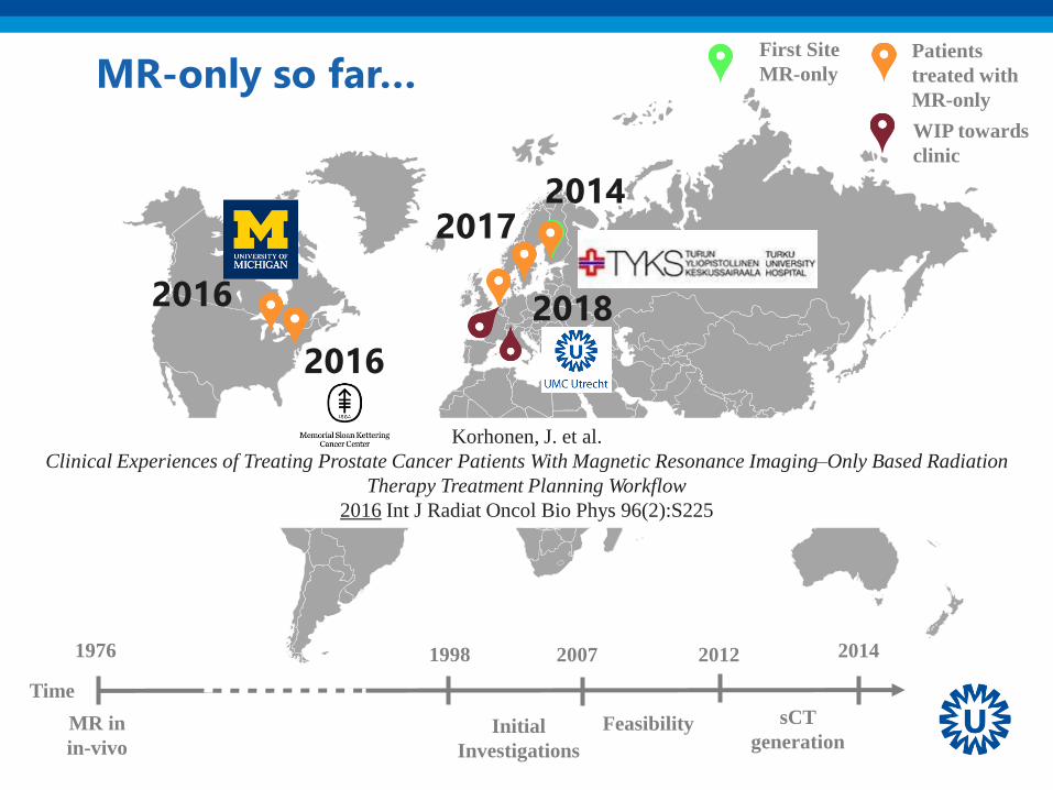
Time
MR-only so far…
1976
MR in
in-vivoInitial
Investigations
2014
sCT
generationFeasibility
1998 2007 2012
Korhonen, J. et al.
Clinical Experiences of Treating Prostate Cancer Patients With Magnetic Resonance Imaging–Only Based Radiation
Therapy Treatment Planning Workflow
2016 Int J Radiat Oncol Bio Phys 96(2):S225
First Site
MR-only
Patients
treated with
MR-only
WIP towards
clinic
2016
2016 2018
20172014

Perspectives5
Outlook
• So far mostly brain & prostate, let’s extend to
– General pelvis, Head & neck
– Towards torso/abdomen!

The big challenge for MRI
Motion
prostate
H&N
Rectum/Gyn
esophagus
low highmedium
brain
swallowing
Bowel
motion
Respiratory
motion
Cardiac
motion
tem
po
ral fr
eq
uen
cyh
igh
low
pancreas
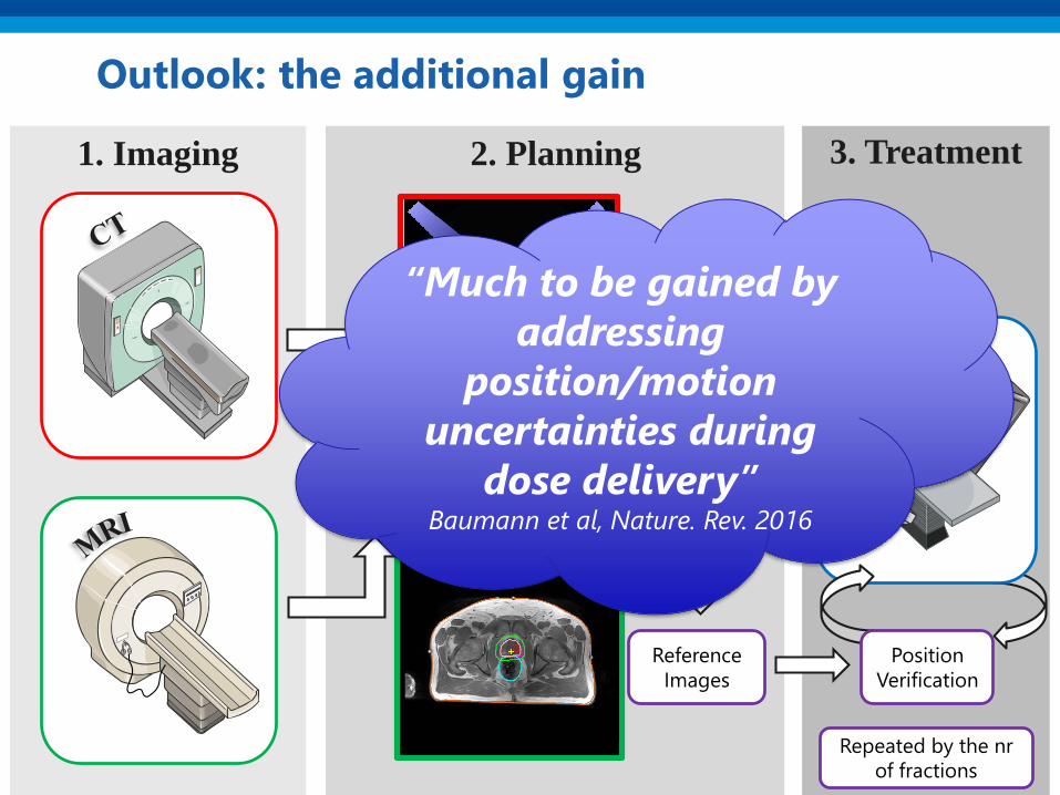
2. Planning 3. Treatment1. Imaging
Outlook: the additional gain
Image
fusion
Reference
Images
Plan &
DoseDelineation
Linac
Position
Verification
Repeated by the nr
of fractions
“Much to be gained by
addressing
position/motion
uncertainties during
dose delivery”Baumann et al, Nature. Rev. 2016

• MR-guided RT promises to
address position/motion
uncertainties
• Integration of MRI and linac
MR-linac, an artistic view before it became reality
MR-guided Radiotherapy?
JJW Lagendijk et al. Semin Radiat Oncol 24:207-209 2014 https://doi.org/10.1016/j.semradonc.2014.02.009

Outlook: MR-only for MR-guided RT
• largely unexplored area
– sCT with dose calculation in a magnetic field
γ
γ
e-
e-
γ
e-
B = 0
γ
γ
e-
e-
γ
e-
B = 1.5 T
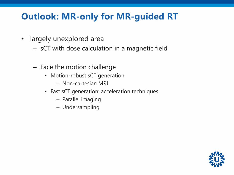
Outlook: MR-only for MR-guided RT
• largely unexplored area
– sCT with dose calculation in a magnetic field
– Face the motion challenge
• Motion-robust sCT generation
– Non-cartesian MRI
• Fast sCT generation: acceleration techniques
– Parallel imaging
– Undersampling

Summary: bring home message
• MR-only Radiotherapy is feasible and a clinical possibility
• Position verification within MR-only can be accurately
performed
• General pelvis and brain are the most largely investigated area
• Commercial solutions are available and can facilitate clinical
implementation
• Each institute currently requires a reasonable effort to
streamline the workflow
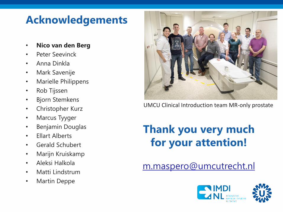
Acknowledgements
• Nico van den Berg
• Peter Seevinck
• Anna Dinkla
• Mark Savenije
• Marielle Philippens
• Rob Tijssen
• Bjorn Stemkens
• Christopher Kurz
• Marcus Tyyger
• Benjamin Douglas
• Ellart Alberts
• Gerald Schubert
• Marijn Kruiskamp
• Aleksi Halkola
• Matti Lindstrum
• Martin Deppe
Thank you very much
for your attention!
UMCU Clinical Introduction team MR-only prostate
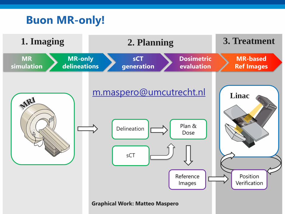
2. Planning
Plan &
Dose
3. Treatment1. Imaging
Buon MR-only!
Reference
Images
Delineation
Linac
Position
Verification
sCT
generation
Dosimetric
evaluation
MR
simulation
MR-only
delineations
MR-based
Ref Images
sCT
Graphical Work: Matteo Maspero


