24
MRC Prodigy Wireless User’s Manual
| Date post: | 02-Jul-2018 |
| Category: |
Documents |
| Upload: | vuongtuong |
| View: | 223 times |
| Download: | 0 times |

MRC Prodigy Wireless
User’s Manual

1 Getting StartedIntroduction ............................................................................................................ 1-1DCC Basic Background ......................................................................................... 1-2Specifications and Features ................................................................................. 1-3System Menu Summary Chart .............................................................................. 1-3
2 OperationQuick Start ............................................................................................................. 2-1
Connecting to Your Layout ............................................................................ 2-1Running a Loco ............................................................................................. 2-1Controlling Accessory Functions .................................................................. 2-2Recalling Locos ............................................................................................. 2-2Saving Locos ................................................................................................ 2-2Deleting Locos ............................................................................................... 2-2Emergency Stopping ..................................................................................... 2-2Speed Steps ................................................................................................... 2-2Yard Mode On/Off ......................................................................................... 2-3Fast Clock ...................................................................................................... 2-3Overload and Short Circuit ........................................................................... 2-3
Cab Setup .............................................................................................................. 2-4Setting Cab Addresses ................................................................................. 2-4Setting the Total Number of Operational Cabs (Cab #1) ............................. 2-4Adding More Than 3 Cabs ............................................................................ 2-4Setting Last Cab Allowed to Program Locos on the Main Track (Cab #1) 2-5Setting Last Cab Allowed to Program on the Program Track (Cab #1) ..... 2-5
Programming Decoders ......................................................................................... 2-5Programming Loco on the Program Track ............................................................ 2-6Programming Locos on the Main Track ................................................................ 2-6Reading Loco’s Decoder Values on the Program Track ..................................... 2-7Configuration Variables – CVs ............................................................................. 2-7
Most Commonly Used CVs ........................................................................... 2-7A Word About CV #29 .................................................................................. 2-8
Consisting .............................................................................................................. 2-9Advanced Consisting .................................................................................... 2-9
Programming Advanced Consists ............................................................ 2-9Running Advanced Consists .................................................................. 2-10Clearing Advanced Consists .................................................................. 2-10
Universal (Old-Style) Consisting ................................................................ 2-10Programming Universal (Old-Style) Consists ........................................ 2-10Running Universal (Old-Style) Consists ................................................ 2-11Clearing Universal (Old-Style) Consists ................................................ 2-11
Fast Clock ............................................................................................................ 2-11Setting Fast Clock (Cab #1) ........................................................................ 2-11Setting Time (Cab #1) .................................................................................. 2-11Setting Time Rate (ratio) (Cab #1) ............................................................. 2-12Setting AM/PM or Military (24hr) Time (Cab #1) ......................................... 2-12
Reverse Loop ...................................................................................................... 2-12Accessory Decoders ......................................................................................... 2-13
Programming Accessory Decoders with CV #513 ................................... 2-13Selecting Accessory Decoders ................................................................. 2-13
Accessory Routes .............................................................................................. 2-14Setting Accessory Decoder Routes (Cab #1) ........................................... 2-14Running Accessory Routes ....................................................................... 2-14Clearing Accessory Routes ....................................................................... 2-14
3 Trouble ShootingGeneral Trouble Shooting ..................................................................................... 3-1Checklist for General Problems ............................................................................ 3-2Special Trouble Shooting ...................................................................................... 3-2
4 Service & Support
Contents-1 MRC Prodigy Wireless
T A
B L
E
O F
C
O N
T E
N T
S

IntroductionThank you for purchasing MRC’s Prodigy Wireless DCC (DigitalCommand Control) system, the finest full duplex DCC radio controlsystem on the market today. MRC’s full duplex system allows you to notonly operate multiple locos using the wireless handheld, but alsoprogram locos from the same wireless handheld on both the ProgramTrack and the Main Track.
Note Although there are Quick-start instructions on the back of the Cab/Handheld, please read these instructions thoroughly to betterunderstand and enjoy your Prodigy Wireless DCC system.
Your Prodigy Wireless system consists of a receiver base unit, a wirelesshandheld transmitter, four-rechargeable, 600mAh NiMH AAA batteries,and a short cord for recharging the wireless handheld.
For best operation, the receiver base unit should not be placed under thelayout in a “tangle of wires” or where scenery mesh screening mayinterfere with the radio transmissions.
The wireless handheld comes complete with on-board rechargeablebatteries. The battery level should be checked prior to using the handheldfor the first time. Best operation is accomplished with fully chargedbatteries. 5.5 volts is maximum voltage, and the handheld should berecharged anytime the indicator reads 4 volts or below.
There is a power switch on the right side of the handheld. The handheldshould be switched off when not in use to conserve battery life, and whenrecharging the on-board batteries. You can use the handheld whilerecharging the batteries; however, this will increase the charge time. Thehandheld has the same cable connection on the bottom as the tetheredhandhelds. To recharge the batteries, simply plug the supplied shortcable into the bottom of the handheld, and the other end of the cable intothe cab jack on your base unit. If you wish, you can substitute four AAAnon-rechargeable alkaline batteries for use. Normal charge time with thehandheld powered off will be approx. 5 hours. If you change the suppliedrechargeable batteries with rechargeable batteries with a higher mAHrating, both the operating time and the charging time will increase.
Caution Do not plug the handheld(s) into the base unit if you installed non-rechargeable alkaline batteries. Non-rechargeable alkaline batteriesare throwaway and are not designed to be recharged. Do not mixalkaline and rechargeable batteries together, and do not attempt torecharge alkaline batteries inside the handheld.
1Getting Started
MRC Prodigy Wireless Getting Started 1-1
1 Getting Started

You can do everything with this wireless handheld that you can do with its“wired” cousins: program on a program track; or program on the main;acquire and run all locos; set up consists & routes; and accessaccessory decoders. Button layout is similar to other MRC Prodigyhandhelds, with the addition of three new buttons:
PROG CV ON MAIN: This button lets you automatically go into CVprogramming of the locomotive you are presently operating withouthaving to press the program button, PROG, and ENTER numerous timesto reach this feature. You can enter this programming mode, change thedecoder’s parameters, and exit the program mode anytime you want andas many times as you want.
SAVE: This button is used to save the last five locos you were operating,or up to any five locos you want to use in your next operating session.
Note Just turning off the wireless handheld power switch does notautomatically save your locomotives in the recall stack for your nextoperating session.
BAT VOLTAGE: This is your battery voltage indicator button. Just press it tomonitor the voltage level present in the on-board batteries; the display willshow bV and the voltage level. 5.5 volts is maximum voltage, and thehandheld should be recharged anytime the indicator reads 4 volts orbelow.
DCC Basic BackgroundA DCC system consists of a DCC Command Station that sends DCCcommands to your layout and DCC decoders installed in your locos thatreceive the DCC commands. Each decoder equipped loco has its ownaddress. Each decoder receives DCC commands but only follows thosecommands matching its address. No more multiple blocks and no moremultiple power packs. With DCC, you can run different locos with differentspeeds and directions all on the same track. You can also turn on/off theloco’s headlight and activate sounds if your loco is equipped with asound decoder. Please visit our website at www.modelrectifier.com formore information about other DCC products.
Please read this manual and your decoder manual carefully beforeinstalling and operating your DCC system.
Note The Prodigy Wireless does not support NON-decoder equipped or analoglocos. MRC’s earlier DCC systems do support running analog locos.However, running analog locos will dramatically slow the response time ofyour DCC system. Therefore, our new Prodigy Wireless does not supportthis old feature.
Info For more information on DCC or MRC DCC systems, visit the Resourcessection of our web site at www.modelrectifier.com or visit the NationalModel Railroad Association’s website at www.nmra.org.
1-2 Getting Started MRC Prodigy Wireless
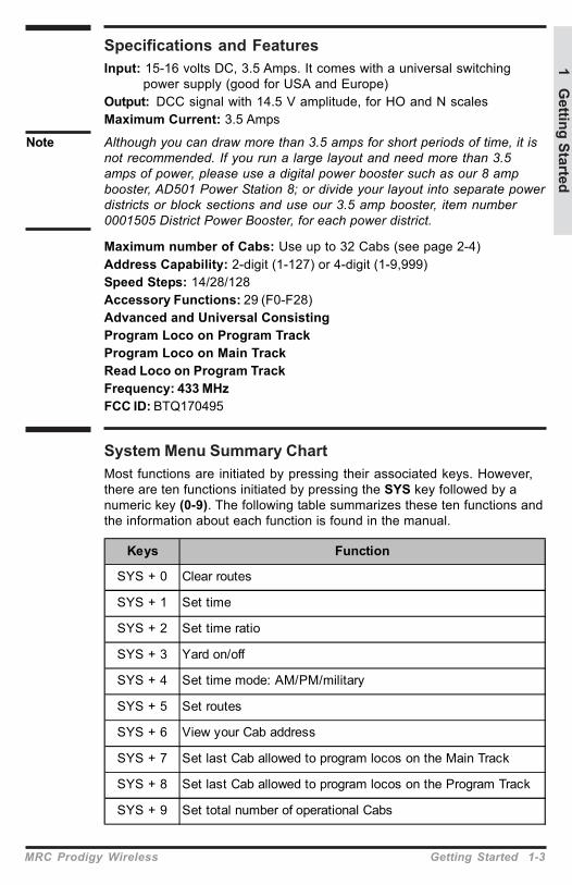
System Menu Summary ChartMost functions are initiated by pressing their associated keys. However,there are ten functions initiated by pressing the SYS key followed by anumeric key (0-9). The following table summarizes these ten functions andthe information about each function is found in the manual.
Keys Function
SYS + 0 Clear routes
SYS + 1 Set time
SYS + 2 Set time ratio
SYS + 3 Yard on/off
SYS + 4 Set time mode: AM/PM/military
SYS + 5 Set routes
SYS + 6 View your Cab address
SYS + 7 Set last Cab allowed to program locos on the Main Track
SYS + 8 Set last Cab allowed to program locos on the Program Track
SYS + 9 Set total number of operational Cabs
Specifications and FeaturesInput: 15-16 volts DC, 3.5 Amps. It comes with a universal switching
power supply (good for USA and Europe)Output: DCC signal with 14.5 V amplitude, for HO and N scalesMaximum Current: 3.5 Amps
Note Although you can draw more than 3.5 amps for short periods of time, it isnot recommended. If you run a large layout and need more than 3.5amps of power, please use a digital power booster such as our 8 ampbooster, AD501 Power Station 8; or divide your layout into separate powerdistricts or block sections and use our 3.5 amp booster, item number0001505 District Power Booster, for each power district.
Maximum number of Cabs: Use up to 32 Cabs (see page 2-4)Address Capability: 2-digit (1-127) or 4-digit (1-9,999)Speed Steps: 14/28/128Accessory Functions: 29 (F0-F28)Advanced and Universal ConsistingProgram Loco on Program TrackProgram Loco on Main TrackRead Loco on Program TrackFrequency: 433 MHzFCC ID: BTQ170495
1 Getting Started
MRC Prodigy Wireless Getting Started 1-3

2-1 Operation MRC Prodigy Wireless
Quick StartConnecting to Your LayoutFollow the diagram to connect the Command Station (base unit) to your
layout.1. Using a small flat-bladed screwdriver,
attach two wires (22 AWG or heavier)from the Main Track layout to theterminals marked Main Track and twowires from the Program Track to theterminals marked Program Track.
2. Plug the power supply into the base unit.3. Plug the AC line cord (110VAC, 60Hz)
into a wall outlet.4. Charge the batteries in the handheld, if
needed.5. Turn power switch on the handheld to
the “On” position.6. Double check all wiring. The power light
should be on and you are ready to runyour decoder equipped locos.
Running a LocoTo run a loco, you have to first know its address. Most decoders youpurchase have the factory default address #3. If you purchase a decoderequipped loco, its address may be its road number. Read your decoderand/or loco manual for your decoder address.To select a loco, press the LOCO key. Using the numeric keypad (0 - 9),enter the loco address. Press ENTER. You have just acquired the loco.The Cab will automatically remember the loco address for later recall.Use the DIRECTION key to set the loco’s direction. Turn the THROTTLEknob slowly to increase the loco’s speed. The selected loco, or currentloco, will begin moving. You can also tap the +1 or -1 to adjust the loco’sspeed. Do not hold the -1 key, since this is also the DEL key and willdelete the loco. To toggle the headlight (F0) on or off, press 0.
Note A blinking loco address indicates that another Cab is also controlling thatloco. This is just a reminder and does not affect your control of the loco.However, since two Cabs are trying to control the same loco simultaneously,the loco may not act as you expect. One operator will have to relinquishcontrol of the loco by deleting the loco from his Cab for proper operation.
2Operation
Prodigy Command Station(base unit)
Power To Main Track
Green Plug
ToProgramTrack

Controlling Accessory FunctionsTo control accessory functions F1 - F9, press 1 - 9. To control F10 - F28,press SHIFT, then input the two digit funtion number. Only funcions up to
F12 will show in the display, F13 to F28will be activated but will not be displayedon the screen.
The left LCD display shows that thecurrent loco is 3802 running in reverse ata speed of 102. Its accessory functions F1and F11 are on.
Recalling LocosTo call up previous locos stored in the memory, press RECALL. You canrecall up to 25 locos.
Saving LocosTo save the last five locos in use for the next operating session, pressSAVE before turning off the handheld’s power switch. Before switching offthe power switch on the handheld, recall back to the five locos you wish touse in your next session, making sure all functions are off and the throttleis set to zero. After you have reset your five locos, press SAVE. Then turnoff the power switch on the handheld and then shut down the power toyour DCC system and layout.
Tip Use the DELETE button to remove any unused locos from the stackbefore saving your favorite five.
Note Although the Cab can recall up to 25 locos for operation, if you “power off”the Cab from the base unit, it will only retain the last five locos previouslysaved. Make sure to press SAVE before powering off.
Deleting LocosThe Cab can store up to 25 locos. If you select a new loco when the Cabis full, the new loco will replace the current loco. The current loco will belost. To prevent this, we recommend you recall unused locos and deletethem by pressing and holding DEL for 2 seconds.
Emergency StoppingFor emergency stopping of the current loco, press STOP. Pressing andholding STOP for 2 seconds will stop the Main Track output. The 2 lightson the base unit will blink. To restore the Main Track output, press andhold STOP for 2 seconds again.
Speed StepsSpeed steps are incremental steps the loco takes to go from 0 to topspeed. There are three speed steps: 14, 28 and 128. The higher the speedsteps setting, the higher the number of different speeds on which the lococan operate. When you enter a new loco address (an address that hasnot been stored in the Cab’s memory), Prodigy Wireless will set 28 speed
F1
Loco
REV SpeedF11
MRC Prodigy Wireless Operation 2-2
2 Operation

2-3 Operation MRC Prodigy Wireless
steps as the default setting for that address. In order to operate your locoproperly, you may need to change the speed steps setting to match thedecoder’s speed steps.To select other speed steps settings, press SPD STEP repeatedly untilyou see your desired speed steps setting. Then press ENTER. Theselected speed steps setting will apply only to that address.
Note Use of the speed step button will not alter the speed step originallyprogrammed into the decoder. It only matches the throttle to the decoder.
Yard Mode On/OffTo toggle the Yard Mode feature on or off, press SYS and 3. In standardthrottle mode, the throttle only controls loco speed. When the Yard Modefeature is on (“Yard” displayed on LCD), the yard throttle will control boththe speed and direction of the loco. Let’s explain how to use the Yardthrottle.When the loco is traveling forward, turning the yard throttle clockwise willincrease the loco’s speed. Turning counterclockwise will decrease itsspeed until 0. Continuing turning counterclockwise will reverse the loco’sdirection. Continuing turning counterclockwise will increase the loco’sspeed in the reverse. Turning clockwise will decrease its speed in thereverse until 0. Continuing turning clockwise will reverse the loco’sdirection and set it forward.
Fast ClockTo view the fast clock, press TIME. The time will replace the addressdisplay on the LCD. You can still run the current loco while the time is
displayed. To return to the loco addressdisplay, press TIME again. The timeinformation is stored in the base unit andtransmitted to the Cab. Each Cabdisplays the same time.
The left LCD display shows time of8:02AM. The current loco is movingforward at a speed of 102.
Overload and Short CircuitThe base unit is rated at 3.5 amps. It is up to you to note how many locosand accessories can be run on the layout at the same time withouttriggering the circuit protector. If there is an overload or short circuit, thebase unit will stop Main Track output for 2 seconds then resume. Pleaseremove the overload or short circuit for proper operation. When operatinglarger layouts with numerous locos and accessories being operated atthe same time or when running 2-rail “O” or “G” scales, you may need aDCC power booster. We recommend you use the MRC Power Station 8 toboost your DCC layout.
AMLoco
FWD TimeSpeed

Cab SetupSetting Cab AddressesYou can use up to 32 Cabs with the Prodigy Wireless. Each Cab musthave a unique address. Any Cab you purchase has the factory defaultaddress #1. Cab #1 is the Master Cab that can perform all functions. Anyadditionally purchased Cabs are also Master Cabs and must have theiraddresses changed from #1 to unique addresses.To view your Cab address, press SYS and 6. The current Cab address willmomentarily display. If you wish to change it, enter a new address (1-32)followed by ENTER. Otherwise, press ENTER to exit. Do not duplicate Cabaddresses.
Setting the Total Number of Operational Cabs (Master Cab Only)The more Cabs in use at one time, the slower the system response isfrom Cab to loco because the base unit can communicate with only oneCab at a time. Setting the total number of operational Cabs will speed upyour Cab’s response time.1. Make sure your Cab is the Master Cab (Cab #1).
Only the Master Cab (Cab #1) can set the number of Cabs allowed tooperate on the DCC layout.
2. Press SYS and 9.3. Using 0 - 9, enter the address of the last operational Cab.
Press ENTER.
Example If you use 10 Cabs and program the Cab addresses #1 - #10, pressingSYS, 9, 10, and ENTER will set the last operational Cab number to 10. Thebase unit will not spend time trying to communicate to Cabs #11 - #32.
If you use 3 Cabs and program the Cab addresses #1 - #3, pressing SYS,9, 3, and ENTER will set the last operational Cab number to 3. The baseunit will only communicate to Cabs #1 - #3. You will have a really fastresponse time.
Adding More CabsThe base unit of your Prodigy Wireless system has one Cab Jack that isused for charging the batteries in the handheld(s) or for connection of onetethered Cab. If you need to use more thethered Cabs or you want toinstall the Cab Jacks around your layout, you will need MRC’s ProdigyWireless Extension Plates (item no. 0001501). With these plates you caneasily install Cab Jacks anywhere around your layout. The wireless baseunit is able to power six tethered Cabs. If more tethered Cabs areneeded, for every five Cabs you need a special extension plate with a builtin power supply (item no. 0001502) to boost power for Cabs. This itemmust be ordered directly from MRC. Please visit our website for moreinformation.
Note The extension plates are not needed if you only use wireless Cabs.
MRC Prodigy Wireless Operation 2-4
2 Operation
2-5 Operation MRC Prodigy Wireless
Setting Last Cab Allowed to Program Locos on the Main Track (MasterCab Only)This feature prevents “novice” operators on your railroad from mistakenlyreprogramming everything on the layout.1. Make sure your Cab is the Master Cab.2. Press SYS and 7.3. Using 0 - 9, enter the number of the last Cab allowed to program on the
Main Track. Press ENTER.
Example If you press the SYS, 7, 3 and ENTER. Cab #4 and above cannot programon the Main Track.
Setting Last Cab Allowed to Program on the Program Track (MasterCab Only)1. Make sure your Cab is the Master Cab.2. Press SYS and 8.3. Using 0 - 9, enter the number of the last Cab allowed to program on the
Program Track. Press ENTER.Example If you press SYS, 8, 2, and ENTER, Cab #3 and above cannot program on
the Program Track.
Programming DecodersThe Prodigy Wireless allows you to easily program most NMRAcompatible decoders. It guides you step by step through theprogramming process. No hexadecimal numbers are needed, nor anengineering degree, to program decoders with this system. The ProdigyWireless allows you to program decoders on a separate Program Trackor on the Main Track layout, all without affecting any other locos operatingon the Main Track.
Decoder TerminologyNote Before you start programming, please familiarize yourself with the
following terminology.Loco Address: The address is the number assigned to a decoder toidentify the decoder.Start Voltage: This is the voltage required to start the loco’s motor andovercome its weight and friction to make it begin to move. You canprogram your loco with a start voltage so that it will begin to move as soonas the throttle is turned.Top Voltage: The top voltage (top speed) is the voltage (speed) at fullthrottle. The Prodigy Wireless top end voltage is set for maximum output.If you are running a switcher, you may want the top end voltage to be lessthan full output for more realistic performance at top throttle setting.Acceleration Rate: This rate simulates the drag of a heavy load as theloco speeds up so when you increase the speed setting, the loco willgradually increase its speed.Deceleration Rate: This rate simulates the drag of a heavy load as theloco slows down so when you decrease the speed setting, the loco willgradually decrease its speed.

Programming Loco on the Program Track1. Make sure your Cab is allowed to program on the Program Track.2. Place the loco on the Program Track. Press PROG to select “Prog Prog
Track”. Press ENTER.3. First, “Adr” will flash, prompting you to program the loco address. Using
0 - 9, enter the loco address followed by ENTER, or press ENTER to skip.Note For the beginner or if you want to only program the loco address, you
can stop right here. Put the loco back on the Main Track. Select the locoby pressing LOCO then enter the loco address and press ENTER. Nowyou can run the loco.4. Next, “SV” will flash, prompting you to program the Start Voltage. Input
data and then press ENTER.5. Next, “Acc” will flash, prompting you to program the acceleration rate.
Input data and then press ENTER.6. Next, “dEc” will flash, prompting you to program the deceleration rate.
Input data and then press ENTER.7. Next, “TV” will flash, prompting you to program the Top Voltage. Input
data then press ENTER.8. Finally, “CV#” will flash, prompting you to program a CV (Configuration
Variable).At this point, you have already finished most of the decoder programming.You can stop programming here by pressing ENTER. The ProdigyWireless allows you to enjoy your model railroading without having todeal with such questions as: What is a CV? What is it for? How do I program it?
9. If you want to program a CV, enter a CV number. Press ENTER. Thenenter CV data. Press ENTER. “CV#” will flash again, prompting you toprogram another CV. To skip, press ENTER.
Note Programming a CV with incorrect data can cause a decoder malfunction.Read your decoder manual carefully before programming a CV. Also,read the Configuration Variables section on the next page.
Programming Locos on the Main TrackProgramming on the Main Track can save you the effort of moving a locoto the Program Track for programming. However, you have to know theloco address in order to program on the Main Track. Otherwise you have toprogram the loco on the Program Track. Not all decoders support theProgram on Main feature. Please read your decoder’s manual to checkwhether the decoder supports this feature.1. Make sure your Cab is allowed to program on the Main Track2. To program on the Main Track, press PROG to select “Prog Main Track”.
Press ENTER. The current loco address will flash, prompting you toprogram the current loco.
3. To program the current loco, press ENTER; to program another loco,enter its address and press ENTER.
4. The rest of the programming procedures are the same as theProgramming on Program Track procedures (see above). Werecommend you bring the loco to a stop before programming because ifthe moving loco has a bad pickup, it may fail to receive the programcommand, causing a malfunction.
MRC Prodigy Wireless Operation 2-6
2 Operation

2-7 Operation MRC Prodigy Wireless
Reading Loco’s Decoder Values on the Program TrackThe Prodigy Wireless DCC system gives you the ability to read back CVvalues of a decoder equipped loco on the Program Track. This feature isuseful if you do not remember the decoder address or what CV valuesyour decoder has. Not all decoders support this feature. Please read yourdecoder’s manual to check whether it supports this feature.1. Place the loco on the Program Track.2. Press PROG to select “rEAd Prog Track” then press ENTER.3. First, “Adr” will flash, prompting you to read the loco address. Press
ENTER to read or press SHIFT to skip to the next item. It may takeseveral seconds to retrieve the address. If the decoder does not supportread back feature, you will receive an “Err” (Error message).
4. Next, “SV” will flash, prompting you to read the Start Voltage. PressENTER to read or SHIFT to skip.
5. Next, “Acc” will flash, prompting you to read the acceleration rate. PressENTER to read or SHIFT to skip.
6. Next, “dEc” will flash, prompting you to read the deceleration rate. PressENTER to read or SHIFT to skip.
7. Next, “TV” will flash, prompting you to read the Top Voltage. PressENTER to read or SHIFT to skip.
8. Finally, “CV#” will flash, prompting you to read a CV. To read a CV, entera CV number and press ENTER. After reading a CV, press ENTER.“CV#” will flash again, prompting you to read another CV. To end theread process, press ENTER.
More about Decoder Read BackNot all decoders support the read back feature. Although Prodigy Wirelesshas read back funtions, it may still fail to read back the decoders. This doesnot mean that your Prodigy Wireless is defective. No DCC system in theworld is able to read all decoders 100%. This will not affect the operation ofthe decoder because you are always able to program your decoder.
Configuration Variables – CVsConfiguration Variables, also known as CVs, receive and hold entereddata that allow the decoder to be tailored to a specific loco or accessory.Some CVs are also called registers.The Prodigy Wireless DCC system allows you to perform most basicprogramming without having to concern yourself with CVs or registers. Ofcourse, if you want to program CVs to custom tailor your decoders orselect certain functions, the Prodigy Wireless has this capability.
Most Commonly Used CVsThe CVs listed on the chart below are contained in almost all decoders, withadditional CVs for extra functions – sound or light – in more specializeddecoders. See the decoder manufacturer’s instruction manual for a list ofCVs contained in that specific decoder and what values to enter for thoseCVs.

A Word About CV #29CV29 is the most important CV of the decoder. Improperly programmingthe CV29 may cause decoder malfunction. We do not recommend youprogram CV29 yourself because the unit will take care of it for you in mostcases. When you program your decoder’s address with Prodigy Wireless,it will automatically program CV29. If you want to reverse the loco’spolarity or set 14 speed steps, you have to reprogram CV29 afterprogramming the loco’s address. Please use the following table toreprogram CV29. The value of CV29 depends on the loco’s address. Forfurther information about CV29, visit the Resource section of our website.
More About Programming Locomotive Address on the Program Trackor Main TrackTo program a locomotive address involves programming a series of CVssuch as CV1, CV17, CV18, CV19 and CV29. This can be somewhatcomplicated. For most decoders, Prodigy Wireless automatically handlesthis for you when programming the loco address. However, it may fail toprogram some old decoders and some new sound decoders made byQSI®. It does not mean that you cannot program these decoders. It onlymeans you cannot use the Prodigy Wireless’s easy addressprogramming feature. For QSI® decoders please refer to your decoder’smanual and use CV programming to program the loco address.
Changes Decoder address 1-127
Decoder address 128-9999
Prodigy Wireless' default setting CV29 = 2 CV29 = 34
Change polarity only CV29 = 3 CV29 = 35
Change to 14 speed steps only CV29 = 0 CV29 = 32
Change polarity & 14 speed steps CV29 = 1 CV29 = 33
2 Operation
CV # Register # Function
1 1 Short address
2 2 Start voltage
3 3 Acceleration rate (momentum)
4 4 Deceleration rate (momenturm)
5 --- Top voltage
6 --- Mid voltage
7 --- Manufacturer version #
8 --- Manufacturer ID #
17 --- Extended address - upper & lower bytes, 4 digit address
18 --- Extended address - upper & lower bytes, 4 digit address
19 --- Advance consist
29 5 Configuration data #1
MRC Prodigy Wireless Operation 2-8

2-9 Operation MRC Prodigy Wireless
Note If you want to program a CV or a group of CVs for the current locomotiveyou are running on the Main Track, press CV and enter the the CVnumber and the data value.For some old decoders, you have to skip the Addr programming and usethe CV program mode to program CV29 with a value of 2 and CV1 with ashort address (1-127). Detailed steps are as follows:1. Press Prog to select Prog Prog Track2. Press Enter six times until CV# displays on the screen3. To select CV29, press 29 and Enter4. CV data displays. Press 2 and Enter5. CV# displays again. Select CV1 by pressing 1 then press Enter6. CV data displays. Press the loco address (1-127) and then Enter
Note Visit our website at www.modelrectifier.com and download the ”Tipsand Tricks” PDF for more information.
ConsistingSometimes more than one loco is needed to haul heavy loads. Thesegrouped locos are known as a multiple unit or a consist. The ProdigyWireless DCC system allows you to build consists quickly and easily.There are two types of consisting methods, Advanced Consisting andUniversal or Old Style Consisting.
Advanced ConsistingYou can only apply Advanced Consisting to a mobile decoder that hasCV19 to support this feature. When you program a loco into an AdvancedConsist, you actually program the consist number into the decoder’sCV19, which will override the decoder’s original address. Therefore, theloco will no longer respond to commands addressed to its originaladdress, but rather only to commands addressed to the consist number.All decoders in the consist will receive the command addressed to theconsist number at the same time and act as one until you clear the consist.The base unit does not hold the consist information. With AdvancedConsists, always remember to clear the consist when you are finished orthe locos will still run as part of the consist next time you use them.
Programming Advanced Consists1. Press CONSIST until “Cons SET” flashes in the LCD display. Then
press ENTER.2. “Cons #” will display, prompting you to enter a consist number. Enter a
consist number (a short address 1-127) followed by ENTER.Note Write down the consist number. You will need it later to clear the
Advanced Consist.3. “Add Loco” will display, prompting you to add a loco into the consist
group. Enter the address of a loco you want to add. Press DIRECTION ifyou want the loco’s direction reversed (forward is the default setting).Then press ENTER.
4. “Add Loco” will display again, prompting you to add another loco intothe consist group. You can add as many locos into the consist as youwould like. To end programming, press ENTER.

Running Advanced ConsistsRunning Advanced Consist is just like running a single loco.After setting up your consist group, use the consist number to run theconsist.1. Press the LOCO key. Make sure “Loco” appears on the LCD. If not,
press the LOCO key again. Enter the consist number and press ENTER.2. Turn the throttle and all the locos in the consist will start moving
together. To control an individual loco’s accessory functions use eitherthe consist number or the loco’s original address. Read your decoder’smanual to find how to control the accessory functions.
Clearing Advanced Consists1. Press CONSIST until “Cons cLr” flashes in the display. Then press
ENTER.2. “Cons#” will display, prompting you to input the consist number. Enter
number of the consist you want to clear and press ENTER.Once you clear the consist, each loco will respond immediately to itsoriginal speed command.
Note If you forget the consist number, each loco’s address in the consist mustbe reprogrammed on the Program Track, or program CV19 to zero, ineach loco.
Universal (Old-Style) ConsistingThis feature allows you to use older decoders that do not have CV19 tosupport Advanced Consisting. In this type of consisting, the base unitstores all the information of the consisting locos and makes them run as asingle loco. When you adjust the speed of the lead loco, the base unitdistributes the speed setting to all the original loco addresses in theconsist by sending the speed command to each individual loco. Althoughthe consist acts as one loco, there is a slight time lag between the locosyou may not be able to detect.Locos consisted in this fashion will revert to their original addresses anddirection settings when removed from the layout. If they are removed fromthe layout and placed back onto the layout during the same session, theywill remain consisted. They will not be “consisted” if removed to anotherlayout.The Prodigy Wireless DCC system allows only ONE Universal Consist ata time regardless of how many Cabs are in use. One Universal Consistper system, not per Cab. Once programmed, the base unit will rememberthe consist group until you clear it. Turning off the base unit power will notclear it.
Programming Universal (Old-Style) Consists1. Press CONSIST until “oLd SET” flashes in the display. Then press
ENTER.2. “LEAd Loc” will flash, prompting you to enter the address of the lead loco.
Enter the lead loco’s address. Press DIRECTION if you want the loco’sdirection reversed (forward is default setting) and press ENTER.
2 Operation
MRC Prodigy Wireless Operation 2-10

2-11 Operation MRC Prodigy Wireless
3. “Add Loco” will flash, prompting you to add another loco into the consistgroup. Enter a loco address. Press DIRECTION if you want the loco’sdirection reversed (forward is default setting) and press ENTER.
4. “Add Loco” will flash again, prompting you to add another loco into theconsist. You can control up to 4 locos total (including the lead loco) in aUniversal Consist. To end programming, press ENTER.
Running Universal (Old-Style) Consists
Note Running a Universal Consist is different from running a single loco.After setting up your consist group, use the lead loco’s address to run theconsist.
1. Press CONSIST then LOCO. Makesure “Cons” appears on the LCDdisplay.
2. Enter the address of the lead locoand press ENTER.
3. Turn the throttle and all the locos inthe consist will start moving together.
4. To control accessory functions, useeach loco’s original address.
The above LCD display shows a Universal Consist group led by lead loco3802 running in reverse at a speed of 102.
Note When running a Universal Consist, LCD shows “Cons.” When running anAdvance Consist, LCD shows “Loco.”
Clearing Universal (Old-Style) ConsistsTo clear a consist, press CONSIST until “Cons oLd cLr” flashes in thedisplay. Then press ENTER. Turning off the power on the base unit will notclear the consist.Once you clear the consist, each loco will immediately respond to itsoriginal speed command.
Note Always clear a Universal (Old-Style) Consist when you are finished withit.
Fast ClockSetting Fast Clock (Master Cab only)
Only the Master Cab (Cab #1) canprogram the time, time ratio, and AM/PM or military (24 hr) time. The timesettings entered by the Master Cab arestored in the Prodigy Wireless DCCsystem base unit memory. Thesettings will remain unchanged untilyou reprogram them. The time is sentto all Cabs operating on the layout sorailroad schedules can be maintained.
Cons
REV Speed
LOCO
FWD TIMESPEED
Setting Time (Master Cab only):1. Make sure your Cab is the Master Cab.2. Press SYS and 1. The current time will be momentarily displayed.3. Enter the new time. Press ENTER.
Setting Time Rate (ratio) (Master Cab only):The time rate is how many real seconds are in one fast clock minute.
Example Rate 1 means that one real second equals one fast clock minute, or 60times as fast as real time. Rate 30 means 30 real seconds equal onefast clock minute, or twice as fast as real time. Rate 60 means 60 realseconds equal one fast clock minute, or real time.1. Make sure your Cab is the Master Cab.2. Press SYS and 2. The current rate will be displayed for a second.3. Enter the new ratio. Press ENTER.
Note For a better understanding of “Scale Time and Distance” versus “RealTime and Distance” refer to the book – “How to Operate Your ModelRailroad” by Bruce Chubb – Kalmbach Publishing.
Setting AM/PM or Military (24hr) Time (Master Cab only):1. Make sure your Cab is the Master Cab.2. Press SYS and 4. Either “AM”, “PM” or nothing (military) will display on
the LCD.3. Repeat step 2 above to select the desired setting.
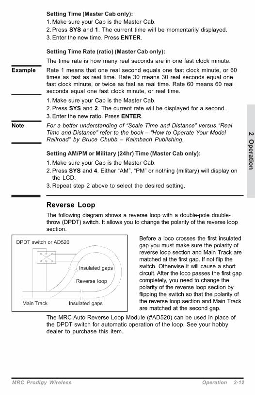
Reverse LoopThe following diagram shows a reverse loop with a double-pole double-throw (DPDT) switch. It allows you to change the polarity of the reverse loopsection.
Before a loco crosses the first insulatedgap you must make sure the polarity ofreverse loop section and Main Track arematched at the first gap. If not flip theswitch. Otherwise it will cause a shortcircuit. After the loco passes the first gapcompletely, you need to change thepolarity of the reverse loop section byflipping the switch so that the polarity ofthe reverse loop section and Main Trackare matched at the second gap.
The MRC Auto Reverse Loop Module (#AD520) can be used in place ofthe DPDT switch for automatic operation of the loop. See your hobbydealer to purchase this item.
DPDT switch or AD520
Insulated gaps
Main Track Insulated gaps
Reverse loop
2 Operation
MRC Prodigy Wireless Operation 2-12

2-13 Operation MRC Prodigy Wireless
Accessory DecodersThe Prodigy Wireless will handle most NMRA compatible accessorydecoders. This type of decoder can operate turnouts (switch tracks) ortoggle accessories, like building lights, on and off from your Cab. Theaccessory decoder outputs can be programmed for a variety of optionsso you can use them for twin-coil switch machines (momentary on), slow-motion switch machines (constant on or latching), or signal lighting(various flash rates). Refer to your accessory decoder’s instructionmanual for programming procedures and CV values.Most accessory decoders have their own unique address (CV #513) andsome have multiple outputs (groups of 4). Accessory decoder’s and locodecoder’s addresses are different, so they can be operatedindependently of each other (even if the address values are the same).
Exception The MRC #AD360 Dispatch Decoder uses a short (1-127) mobiledecoder address. You can treat the MRC #AD360 as a loco decoder anduse accessory functions F1 and F2 to operate it. It is very easy to use andprogram. No accessory address programming is needed.
Programming Accessory Decoders with CV #5131. Press PROG until you reach “Prog Prog Track.”2. Press ENTER until “CV #” displays.3. Enter 513. Press ENTER.4. Enter the accessory decoder address. Press ENTER.
Read your accessory decoder manual for proper addressing.
Selecting Accessory Decoders1. Press ACCY. Using 0 - 9, enter the accessory decoder address. Press
ENTER.2. “1or2” will display reminding you to press only 1 or 2 to control the
accessory. Press 1 to turn the accessory on and 2 to turn it off. You cankeep pressing 1 or 2 until you are done with accessory.
3. Press ENTER to escape accessory operation.
Note Some other manufacturer’s accessory decoders program differently thandescribed above. See the “Tips and Tricks” PDF on our website forupdated information on programming these types of accessory decoders.

MRC Prodigy Wireless Operation 2-14
Accessory RoutesGrouping of turnouts (or accessories) can be consisted to form a route.The Prodigy Wireless DCC system allows up to 31 routes and up to 8accessories in each route. Please do not set a route number higher than31, nor add more than 8 accessories into one route.
Setting Accessory Decoder Routes (Master Cab only)1. Press SYS and 5.2. “Route SET” appears in display. Press ENTER.3. Enter route number (1 – 31). Press ENTER.4. “Add Accy #” will display. Using 0 - 9, enter an accessory address (1 to
255).If you want this accessory (turnout points) to move in a directionopposite its normally programmed direction (reverse polarity), useDIRECTION to set its direction. Press ENTER.
5. “Add Accy #” will display again, prompting you to add another accessoryinto the route. Repeat above steps to enter up to 8 accessories into oneroute.
6. When finished setting up your route, press ENTER.
Running Accessory Routes1. Press ROUTE. Enter the Route number you wish to run. Press ENTER.2. “1or2” will display reminding you to press only 1 or 2 to select the
routes.
Clearing Accessory Routes (Master Cab only)1. Press SYS and 0. Then press ENTER.2. Enter the route number. Then press ENTER.
2 Operation

3Trouble Shooting
General Trouble ShootingIt takes the Command Station, the decoders and your layout to make theDCC system work. This Trouble Shooting Section has been arranged in amanner easiest for you to find the cause of your problem. Please gothrough this section in the exact order it appears because each followingset of instructions assumes that the preceding set has been tested andthat component of the DCC system found not defective.1. Plug in the power supply of the base unit. The pilot light should turnon. If not, make sure the power supply is securely plugged into the baseunit and into a working AC wall outlet. Then unplug the power, wait 3seconds and plug back in. If power light still does not turn on, send theunit in for repair.2. Check the Main Track output. Place an analog loco or test light on theMain Track. The loco should buzz or the test light should light. If not, checkall connections and make sure the rear green plug is securely pluggedin. Make sure the screws on the green plug are tightened on the wire andnot on the wire cover (insulator). If the analog loco still does not buzz or thetest light does not light, send the unit in for repair. It is better to use aV.O.M (multi-meter) on the A.C. scale to check for track power, as DCCtrack power is A.C., not D.C.3. LCD does not display anything. The Cab LCD should display thecurrent loco when the power is on. If not, check the battery voltage level.If recharging the batteries does not help, send unit in for repair.4. Check the communication between the base unit and the Cab.Press 2. F2 should momentarily display on the LCD and the Link lightshould blink. If not, set the Cab to be the Master Cab (Cab #1) bypressing SYS, 6, 1, and ENTER. Make sure there is no other Master Cabin the system and try again. If there is still no communication, send theunit in for repair. If there is communication, you may have the wrong Cabsetup. Read the Cab Setup section.5. Your loco may have a pickup problem. You should periodically cleanyour track and your loco’s wheels. Oxide coating or dirt on either the trackor loco’s wheels often causes intermittent and jerky operation.
If you pass the above steps, your Command Station and Cabs are fine.The problem may lie in the decoder.
6. Your decoder may have lost its memory or is in Advanced Consistmode (CV19 is not 0). Reprogram the loco address and try again.7. Your decoder may have too much momentum. Program the loco withzero acceleration and deceleration rates.8. The base unit may have a Universal Consist controlling yourdecoder. Clear the old consist by pressing CONSIST until “Cons oLd cLr”flashes in the display. Then press ENTER.
3-1 Trouble Shooting MRC Prodigy Wireless

9. The current loco speed command may not match the decoder’sspeed steps. Reprogram your decoder’s address. When you program thedecoder with Prodigy Wireless it will automatically set the decoder’sspeed steps to 28/128. Select 28 or 128 speed steps on the base unitand then try to run the loco.10. Check the decoder wiring and make sure everything is correctlyinstalled.11. Remove the decoder and test it on a decoder tester to make surethe decoder is fine.12. If the decoder is fine, check the loco to make sure the loco is finebefore installing the decoder.
Checklist for General Problems1. Clean your layout and the loco’s wheels.2. Check the layout’s wiring.3. Reprogram loco address and other data.4. Check battery voltage level.5. Reset the base unit by unplugging power supply.6. Check loco for proper decoder installation.7. Check wiring from the base unit to your layout.8. Check for short circuits and/or stray objects lying across track rails.9. Make sure the Link light flashes when you press F2.
Special Trouble ShootingBase unit power light is on but Cab does not display anything on theLCD display1. Check the Cab battery voltage level.2. Replace the batteries, if needed.3. Try another Cab.
The loco’s headlight turns itself offWhen you press 0 to turn on the loco’s headlight, the base unit will sendthe command to the decoder to turn on the loco’s headlight. The baseunit will not continuously send the accessory command to the decoderlike the speed command. When the loco hits a dirty track and loses itspower, it will reset and lose the accessory command. You should cleanthe track and the loco’s wheel to improve the loco’s pickup.
During operation all locos stop respondingUnplug the power supply, wait 3 seconds and turn the power back on. If allthe locos start to run and the system shuts down again, you may have toomany locos and accessories connected to track power. Remove some locosand try again.
Your loco doesn’t work while other locos workThe decoder may have lost its memory. Reprogram loco address.
3 Trouble Shooting
MRC Prodigy Wireless Trouble Shooting 3-2

Your Cab doesn’t work while other Cabs workMake sure each Cab address is unique. Make sure your Cab address is anoperational address. Check battery voltage. If the Cab still does not work, itmay be a defective Cab.
Your Cab operates locos but cannot program on the Program Track1. If the Link light does not flash when you enter a data and press ENTER,
it may have been limited by the Master Cab and is not allowed toprogram on the Program Track.
2. If the Link light flashes when you enter a data and press ENTER, thentest the Program Track output. To test, place an analog loco on theProgram Track. During the programming process, the Link light shouldbe on and the analog loco should buzz. If the Link light is on and theanalog loco does not buzz, it is a defective Program Track output.
Your Cab operates locos but cannot program on the Main TrackIt may have been limited by the Master Cab.Your Cab operates locos but cannot program an Advanced ConsistIt may have been limited by the Master Cab. Your Cab must be able toprogram on the Main Track to set an Advanced Consist.
3-3 Trouble Shooting MRC Prodigy Wireless

4Service & Support
4 Service & Support
MRC Prodigy Wireless Service & Support 4-1
Your Prodigy Wireless DCC has been thoroughly tested at the factory. Donot shut down your layout unnecessarily.Before returning your unit for repair or servicing, please read both GeneralTrouble Shooting and Special Trouble Shooting sections to make certainthe unit is defective. Please visit our website at www.modelrectifier.com forfurther Prodigy Wireless information before calling our service department at(732) 225-6360 before returning your unit.Please have the following information handy when you call:
1. Name and model number of the power supply, including the powerbooster (if applicable) used with the Prodigy Wireless DCC.
2. Name of the manufacturer and the type of decoders and locos youare using.
Return ProcedureIf it should become necessary to return your DCC system, include aclearly printed letter with your name, address, daytime telephone numberand a detailed description of the problem you are experiencing. Pleasealso include a $25.00 check to cover shipping and handling.
Note Warranty does not include abuse, neglect or using this product foranything other than its intended purpose. Warranty coverage will behandeled on a case by case basis, and other charges may apply forrepair and/or replacement of the product.
Send your Prodigy Wireless DCC system by Parcel Post Insured orUnited Parcel Service to: Model Rectifier Corporation
Attn: Customer Service Dept.80 Newfield AvenueEdison, NJ 08837
This device complies with Part 15 of the FCC Rules. Operation is subjectto the following two conditions: (1) this device may not cause harmfulinterference, and (2) this device must accept any interference received,including interference that may cause undesired operation.FCC ID: BTQ170495
FCC Compliance

© 2007 Model Rectifier Corporation80 Newfield Avenue
Edison, NJ 08837www.modelrectifier.com
Printed in USA


